EP3633097A1 - Dämpfer und steuerungsverfahren dafür - Google Patents
Dämpfer und steuerungsverfahren dafür Download PDFInfo
- Publication number
- EP3633097A1 EP3633097A1 EP18806226.9A EP18806226A EP3633097A1 EP 3633097 A1 EP3633097 A1 EP 3633097A1 EP 18806226 A EP18806226 A EP 18806226A EP 3633097 A1 EP3633097 A1 EP 3633097A1
- Authority
- EP
- European Patent Office
- Prior art keywords
- light emitting
- power switch
- emitting unit
- steamer
- battery
- Prior art date
- Legal status (The legal status is an assumption and is not a legal conclusion. Google has not performed a legal analysis and makes no representation as to the accuracy of the status listed.)
- Granted
Links
Images

Classifications
-
- D—TEXTILES; PAPER
- D06—TREATMENT OF TEXTILES OR THE LIKE; LAUNDERING; FLEXIBLE MATERIALS NOT OTHERWISE PROVIDED FOR
- D06F—LAUNDERING, DRYING, IRONING, PRESSING OR FOLDING TEXTILE ARTICLES
- D06F75/00—Hand irons
- D06F75/08—Hand irons internally heated by electricity
- D06F75/10—Hand irons internally heated by electricity with means for supplying steam to the article being ironed
- D06F75/20—Arrangements for discharging the steam to the article being ironed
-
- D—TEXTILES; PAPER
- D06—TREATMENT OF TEXTILES OR THE LIKE; LAUNDERING; FLEXIBLE MATERIALS NOT OTHERWISE PROVIDED FOR
- D06F—LAUNDERING, DRYING, IRONING, PRESSING OR FOLDING TEXTILE ARTICLES
- D06F73/00—Apparatus for smoothing or removing creases from garments or other textile articles by formers, cores, stretchers, or internal frames, with the application of heat or steam
-
- D—TEXTILES; PAPER
- D06—TREATMENT OF TEXTILES OR THE LIKE; LAUNDERING; FLEXIBLE MATERIALS NOT OTHERWISE PROVIDED FOR
- D06F—LAUNDERING, DRYING, IRONING, PRESSING OR FOLDING TEXTILE ARTICLES
- D06F67/00—Details of ironing machines provided for in groups D06F61/00, D06F63/00, or D06F65/00
- D06F67/10—Driving arrangements
-
- D—TEXTILES; PAPER
- D06—TREATMENT OF TEXTILES OR THE LIKE; LAUNDERING; FLEXIBLE MATERIALS NOT OTHERWISE PROVIDED FOR
- D06F—LAUNDERING, DRYING, IRONING, PRESSING OR FOLDING TEXTILE ARTICLES
- D06F75/00—Hand irons
- D06F75/34—Handles; Handle mountings
-
- D—TEXTILES; PAPER
- D06—TREATMENT OF TEXTILES OR THE LIKE; LAUNDERING; FLEXIBLE MATERIALS NOT OTHERWISE PROVIDED FOR
- D06F—LAUNDERING, DRYING, IRONING, PRESSING OR FOLDING TEXTILE ARTICLES
- D06F79/00—Accessories for hand irons
-
- D—TEXTILES; PAPER
- D06—TREATMENT OF TEXTILES OR THE LIKE; LAUNDERING; FLEXIBLE MATERIALS NOT OTHERWISE PROVIDED FOR
- D06F—LAUNDERING, DRYING, IRONING, PRESSING OR FOLDING TEXTILE ARTICLES
- D06F87/00—Apparatus for moistening or otherwise conditioning the article to be ironed or pressed
Definitions
- the present disclosure relates to a steamer and a method of controlling the same, and more particularly to a steamer, which may spray stream onto laundry for ironing, and a method of controlling the same.
- washing machines which sequentially perform washing, rinsing, and spin-drying operations, are a typical example of the laundry treatment apparatus.
- the washing machine is generally classified into a top-loading washing machine and a front-loading washing machine (also called a drum washing machine).
- the top-loading washing machine performs washing of the laundry by using a rotating water stream generated in wash water.
- the front-loading washing machine performs washing of the laundry by friction between laundry items that is generated when the laundry items are lifted and dropped by a lifter installed at an inner circumference of a drum.
- Typical methods of ironing the laundry include: a method of ironing by using an iron while the laundry is placed on an ironing board; and a method of ironing by using a steamer which sprays steam onto the laundry while the laundry is hung on a hanger.
- a direction of spraying steam onto the laundry is changed according to a position of a user's arm, such that steam may not be sprayed uniformly onto the laundry, and wrist strain may be caused when a user struggles to spray steam uniformly onto the laundry.
- a steamer including: a handle having a hinge formed at one end in a longitudinal direction thereof, the hinge protruding in a direction orthogonal to the longitudinal direction; a head which is rotatably connected to the hinge and sprays steam; a motor which rotates the head about the hinge; a sensor which senses an inclination in the longitudinal direction of the handle with respect to a horizontal line; and a controller which according to the inclination sensed by the sensor, operates the motor to rotate the head to a position at which the head sprays steam horizontally.
- the steamer may further include a power switch disposed at the handle, wherein the sensor may sense the inclination when the power switch is turned on, and while the power switch is turned on, the controller may operate the motor to rotate the head to a position at which the head sprays the steam horizontally, according to the inclination sensed by the sensor.
- the controller may operate the motor to rotate the head to an original position when the power switch is turned off.
- the steamer may further include a power switch disposed at the handle, a steam spray switch disposed at the handle, and a light emitting unit which generates and emits light, wherein when the power switch is turned on, the controller may control the light emitting unit to emit light in first color, and when the power switch and the steam spray switch are turned on, the controller may control the light emitting unit to flicker in the first color or to emit light in second color.
- the steamer may further include a power switch disposed at the handle, a battery, and a light emitting unit which generates and emits light, wherein when the power switch is turned on, the controller may control the light emitting unit to emit light in first color, and when the power switch is turned on and a charge amount of the battery is equal to or lower than a first predetermined value, the controller may control the light emitting unit to emit light in second color.
- the steamer may further include a wireless charging part to charge the battery, wherein when the power switch is turned off and the wireless charging part charges the battery, in response to the charge amount of the battery being equal to or lower than a second predetermined value which is greater than the first predetermined value, the controller may control the light emitting unit to flicker in the first light or to emit light in the second color, and in response to the charge amount of the battery being greater than the second predetermined value, the controller may control the light emitting unit to emit light in third color.
- a steam-spraying direction of the head is maintained horizontal, such that steam may be sprayed uniformly onto the laundry, which facilitates ironing of the laundry.
- the head when a user turns on the power switch, the head may rotate to a position at which the head may spray steam uniformly.
- the head when the user turns off the power switch, the head may automatically rotate to an original position, such that the steamer may be easily stored in a storage space.
- At least one of a light emitting pattern and a light emitting color of the light emitting unit is different to differentiate between when the steamer sprays steam and when the steamer does not spray steam, thereby enabling a user to easily recognize an operation state of the steamer seeing at least one of the light emitting pattern and the light emitting color.
- At least one of the light emitting pattern and the light emitting color of the light emitting unit is different according to a charge amount of the battery, thereby enabling the user to easily recognize whether it is required to charge the battery by seeing at least one of the light emitting pattern and the light emitting color.
- At least one of the light emitting pattern and the light emitting color of the light emitting unit is different according to a charge amount of the battery, thereby enabling the user to easily recognize whether the battery is fully charged by seeing at least one of the light emitting pattern and the light emitting color.
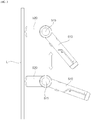
- FIG. 1 is a perspective view of a steamer according to a first embodiment of the present disclosure.
- the steamer 4 includes a handle 510 and a head 520.
- the handle 510 is a portion held by a user's hand, has a cross-section of a circular shape, and may be formed to be elongated.
- the cross-sectional shape of the handle 510 is not limited to a circular shape.
- the cross-sectional shape of the handle 510 may be formed in a square shape, or may be modified into various other shapes.
- a battery 511 may be detachably connected to the handle 510.
- the battery 511 may be charged with power.
- the steamer 4 may operate by using the power of the battery 511.
- a wireless charging part 512 may be provided in the handle 510.
- the wireless charging part 512 may wirelessly charge the battery 511.
- the wireless charging part 512 may include a coil which electrically reacts with a charging coil of a wireless charging unit (not shown) that is provided separately from the steamer 4, and the battery 511 may be charged by electrical reaction of the charging coil and the coil.
- the handle 510 may include a water container for storing water, and a spray nozzle for fine spray of water stored in the water container so that water particles may be sprayed.
- the head 520 may be provided with a heater which applies heat to the water particles sprayed from the nozzle so that the water particles are phase-changed into steam.
- a power switch 513 may be provided at the handle 510.
- the power switch 513 may be turned on or off by a user. In the case where the power switch 513 is turned on, the steamer 4 of the battery 511 may be operated.
- the power switch 513 is disposed at an upper portion of the handle 510 so as to be turned on or off by a user's thumb.
- a steam spray switch 514 may be disposed at the handle 510.
- the steam spray switch 514 may be turned on or off by a user. In the case where the steam spray switch 514 is turned on, the head 520 may spray steam to the outside; and in the case where the steam spray switch 514 is turned off, the head 520 may not spray steam to the outside.
- the steam spray switch 514 is disposed at a lower portion of the handle 510 to be turned on or off by a user's forefinger. When being pressed by a user's forefinger, the steam spray switch 514 may be turned on, and when the pressed switch is released, the steam spray switch 514 may be turned off.
- a hinge 515 may protrude in a direction orthogonal to the longitudinal direction.
- the hinge 510 may protrude on both sides at one end in a longitudinal direction of the handle 510.
- the head 520 may be rotatably connected to the hinge 515 of the handle 510.
- the head 520 may rotate about the hinge 515.
- the head 520 may spray steam to the outside.
- a spray hole 523, which sprays the steam to the outside, may be provided at a front surface of the head 520.
- a flow path direction of the spray hole 523 may be formed orthogonal to a protruding direction of the hinge 515. That is, the head 520 may spray steam toward a front side from a rear side thereof, and the hinge 515 may protrude on both the left side and the right side at one end in a longitudinal direction of the handle 510.
- the head 520 may include: a cylindrical part 521 which is rotatably connected to the hinge 515; and a spray part 522 which extends forward from a circumferential surface of the cylindrical part 521 and has a front surface from which steam is sprayed.
- the spray part 522 may include a cavity and the front surface may be open.
- the open front surface of the spray part 522 may be provided with the spray hole 523 that sprays the steam.
- the spray part 522 may be formed in a hexahedral shape with an open front surface, and may be formed in a cylindrical shape with an open front surface.
- the shape of the spray hole 522 is not limited to the hexahedral shape or the cylindrical shape, and may be modified into various other shapes.
- a light emitting unit 524 may be disposed on both sides of the cylindrical part 521.
- the light emitting unit 524 is formed in a ring shape corresponding to a circumference of the cylindrical part 521, and may be connected to the circumference on both sides of the cylindrical part 521.
- the light emitting unit 524 may generate and emit light.
- the light emitting unit 524 may include a light emitting diode (LED).
- the light emitting unit 524 may emit light in a plurality of colors. For example, the light emitting unit 524 may emit light in blue and red, or emit light in blue, red, and green.
- the light emitting unit 524 may include a light emitting diode, which generates blue light, and a light emitting diode which generates red light.
- the light emitting unit 524 may include a light emitting diode which generates blue light, a light emitting diode which generates red light, and a light emitting diode which generates green light.
- FIG. 2 is a control block diagram illustrating a steamer according to a first embodiment of the present disclosure
- FIG. 3 is a side view illustrating an operation of a steamer according to a first embodiment of the present disclosure.
- the steamer 4 may further include a motor 530, a sensor 540, and a controller 550.
- the motor 530 may be disposed in the hinge 515 of the handle 510.
- a circular gear having gear teeth formed on a circumference thereof may be connected to a rotation axis of the motor 530.
- a ring gear, which is engaged with the circular gear may be connected to an inner circumference of the cylindrical part 521 of the head 520. Accordingly, the motor 530 may rotate the head 520 about the hinge 515.
- the sensor 540 may be disposed in the handle 510.
- the sensor 540 may sense an inclination in a longitudinal direction of the handle 510 with respect to a horizontal line.
- the inclination sensed by the sensor 540 may be input to the controller 550.
- the sensor 540 may be a gyro sensor.
- the controller 550 may be disposed in the handle 510.
- the controller 550 may control the light emitting unit 524 by using an ON/OFF signal input from the power switch 513.
- the controller 550 may control the light emitting unit 524 by using an ON/OFF signal input from the power switch 513 and an ON/OFF signal input from the steam spray switch 514.
- the controller 550 may control the motor 530 by using an ON/OFF signal input from the power switch 513, and the inclination of the longitudinal direction of the handle 510 with respect to the horizontal line which is input from the sensor 540.
- the controller 550 may operate the motor 530 to rotate to a position where the head 520 may spray the steam horizontally. Accordingly, as illustrated in FIG. 3 , in the case of ironing laundry L hung on a hanger (not shown) by using the steamer 4, even when the inclination of the handle 510 is changed, the head 520 may be maintained at a position at which the head 520 may continuously spray the steam horizontally. That is, when a user holds the handle 510 with a hand to spray the steam forward and downward of the laundry L, the inclination of the handle 510 is changed, but the head 520 may be maintained at a position at which the head 520 may continuously spray the steam horizontally. Accordingly, the steamer 4 may uniformly spray the steam to the laundry L to iron the laundry L, and wrist strain is not caused when a user irons the laundry L.
- the sensor 540 may sense the inclination when the power switch 513 is turned on. Once the power switch 513 is turned on, the controller 550 may operate the motor 530 to rotate the head 520 to a position at which the head 520 may spray the steam horizontally.
- the controller 550 may operate the motor 530 to rotate the head 520 to an original position.
- the original position of the head 520 is a position where a longitudinal direction of the head 520 coincides with a longitudinal direction of the handle 510. Accordingly, when the head 520 rotates to an original position, the overall shape of the handle 510 and the head 520 becomes a linear shape.
- the controller 550 may control the light emitting unit 524 to emit light in first color.
- the first color may be blue. That is, once the power switch 513 is turned on, the controller 550 may control the light emitting unit 524 to emit light in blue. Upon seeing that the light emitting unit 524 emits light in blue, a user may recognize that the power switch 513 is turned on.
- the controller 550 may control the light emitting unit 524 to flicker in the first color. That is, with the power switch 513 turned on, when a user turns on the steam spray switch 514 to spray steam, the light emitting unit 524 may flicker in the first color. For example, while a user turns on the power switch 513 and the light emitting unit 524 emits light in blue, when the user turns on the steam spray switch 514 to spray steam, the light emitting unit 524 may flicker in blue. Upon seeing that the light emitting unit 524 flickers in blue, the user may recognize that the steam spray switch 514 is turned on and the steam is sprayed.
- the controller 550 may control the light emitting unit 524 to emit light in second color.
- the second color may be red. That is, when the power switch 513 and the steam spray switch 514 are turned on, the controller 550 may control the light emitting unit 524 to light emit in red. While a user turns on the power switch 513 and the light emitting unit 524 emits light in blue, when the user turns on the steam spray switch 514 to spray steam, the light emitting unit 524 may emit light in red. Upon seeing that the light emitting unit 524 emits light in red, the user may recognize that the steam spray switch 514 is turned on and the steam is sprayed.
- the controller 550 may determine that it is required to charge the battery 511, and controls the light emitting unit 524 to flicker in the first color. While the power switch 513 is turned on and the light emitting unit 524 flickers in the first color, a user may determine that is required to charge the battery 511, and may charge the battery 511. That is, in the case where the power switch 513 is turned on, and the light emitting unit 524 flickers light in blue, the user may determine that it is required to charge the battery 511, and may charge the battery 511.
- the controller 550 may determine that it is required to charge the battery 511, and controls the light emitting unit 524 to flicker in the second color. While the power switch 513 is turned on and the light emitting unit 524 emits light in the second color, a user may determine that it is required to charge the battery 511, and may charge the battery 511. That is, in the case where the power switch 513 is turned on, and the light emitting unit 524 emits light in red, the user may determine that it is required to charge the battery 511, and may charge the battery 511.
- the controller 511 may determine that the battery 511 is not fully charged, and may control the light emitting unit 524 to flicker in the first color; and in the case where a charge amount of the battery 511 is greater than the second predetermined value, the controller 550 determines that the battery 511 is fully charged, and controls the light emitting unit 524 to emit light in the first color.
- the controller 511 may determine that the battery 511 is not fully charged, and may control the light emitting unit 524 to emit light in the second color; and in the case where a charge amount of the battery 511 is greater than the second predetermined value, the controller 550 may determine that the battery 511 is fully charged, and may control the light emitting unit 524 to emit light in third color.
- the third color may be green.
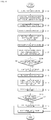
- FIG. 4 is a flowchart illustrating a method of controlling a steamer according to a first embodiment of the present disclosure. Here, the method of controlling the steamer will be described in connection with the operation of the steamer.
- the power switch 513 is turned on to use the steamer 4 in S101.
- the sensor 540 senses the inclination in the longitudinal direction of the handle 510 with respect to a horizontal line, and inputs the sensed inclination to the controller 550. Then, the controller 550 controls the light emitting unit 524 to emit light in blue which is the first color in S102.
- the controller 550 operates the motor 530 to rotate the head 520 to a position where the head 520 may spray steam horizontally in S103.
- a user moves the handle 510 up and down while holding it with hand in order to iron the laundry L hung on a hanger, an angle of the user's arm is changed, such that the inclination of the handle 510 is continuously changed, and the head 520 continuously rotates, by a driving force of the motor 530, to a position at which the head 520 may spray the steam horizontally.
- the user puts the spray hole 523 of the head 520 on the laundry L, and turns on the steam spray switch 514 in S104. Then, the head 520 sprays steam onto the laundry L through the spray hole 523, and the controller 550 controls the light emitting unit 524 to flicker in blue which is the first color in S105.
- the user turns off the steam spray switch 514 in S106. Then, the head 520 stops spraying, and the controller 550 controls the light emitting unit 524 to emit light in blue which is the first color in S107.
- the controller 550 may determine whether a charge amount of the battery 511 is equal to or lower than the first predetermined value in S108. While the power switch 513 is turned on, in the case where the charge amount of the battery 511 is greater than the first predetermined value, the controller 550 controls the light emitting unit 524 to continue to emit light in blue which is the first color in S107. Further, while the power switch 513 is turned on, in the case where the charge amount of the battery 511 is equal to or lower than the first predetermined value, the controller 550 controls the light emitting unit 524 to flicker in blue which is the first color in S109.
- the user Upon finishing ironing the laundry L, the user turns off the power switch 513 in S110. Then, the head 520 rotates to an original position, and the light emitting unit 524 is turned off and does not emit light in S111.
- the original position of the head 520 is a position where a longitudinal direction of the head 520 coincides with a longitudinal direction of the handle 510, such that when the head 520 rotates to the original position, the overall shape of the handle 510 and the head 520 becomes a linear shape.
- the controller 550 determines whether a charge amount of the battery 511 is equal to or lower than the second predetermined value which is greater than the first predetermined value in S113. In the case where the charge amount of the battery 511 is lower than the second predetermined value, the controller 550 determines that the battery 511 is not fully charged and controls the light emitting unit 524 to flicker in blue which is the first color in S114. Further, in the case where the charge amount of the battery 511 is greater than the second predetermined value, the controller 550 determines that the battery 511 is fully charged, and controls the light emitting unit 524 to emit light in blue which is the first color in S115.
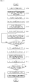
- FIG. 5 is a flowchart illustrating a method of controlling a steamer according to a second embodiment of the present disclosure.
- the power switch 513 is turned on to use the steamer 4 in S201.
- the sensor 540 senses the inclination in the longitudinal direction of the handle 510 with respect to a horizontal line and inputs the sensed inclination to the controller 550. Then, the controller 550 controls the light emitting unit 524 to emit light in blue which is the first color in S202.
- the controller 550 controls the motor 530 to rotate the head 520 to a position at which the head 520 may spray steam horizontally in S203.
- the angle of the user's arm is changed, such that the inclination of the handle 510 is continuously changed, and the head 520 continuously rotates, by a driving force of the motor 530, to a position at which the head 520 may spray the steam horizontally.
- the user puts the spray hole 523 of the head 520 on the laundry L, and turns on the steam spray switch 514 in S204. Then, the head 520 sprays steam onto the laundry L through the spray hole 523, and the controller 550 controls the light emitting unit 524 to emit light in red which is the second color in S205.
- the user turns off the steam spray switch 514 in S206. Then, the head 520 stops spraying, and the controller 550 controls the light emitting unit 524 to emit light in blue which is the first color in S207.
- the controller 550 may determine whether a charge amount of the battery 511 is equal to or lower than the first predetermined value in S208. While the power switch 513 is turned on, in the case where the charge amount of the battery 511 is greater than the first predetermined value, the controller 550 controls the light emitting unit 524 to continue to emit light in blue which is the first color in S207. Further, while the power switch 513 is turned on, in the case where the charge amount of the battery 511 is equal to or lower than the first predetermined value, the controller 550 controls the light emitting unit 524 to emit light in red which is the second color in S209.
- the user Upon finishing ironing the laundry L, the user turns off the power switch 513 in S210. Then, the head 520 rotates to an original position, and the light emitting unit 524 is turned off and does not emit light in S211.
- the original position of the head 520 is a position where a longitudinal direction of the head 520 coincides with a longitudinal direction of the handle 510, such that when the head 520 rotates to the original position, the overall shape of the handle 510 and the head 520 becomes a linear shape.
- the controller 550 determines whether a charge amount of the battery 511 is equal to or lower than the second predetermined value which is greater than the first predetermined value in S213. In the case where the charge amount of the battery 511 is lower than the second predetermined value, the controller 550 determines that the battery 511 is not fully charged and controls the light emitting unit 524 to emit light in red which is the second color in S214. Further, in the case where the charge amount of the battery 511 is greater than the second predetermined value, the controller 550 determines that the battery 511 is fully charged, and controls the light emitting unit 524 to emit light in green which is the third color in S215.
- a steam-spraying direction of the head 520 is maintained horizontal, such that steam may be sprayed uniformly onto the laundry L, which facilitates ironing of the laundry L.
- the head 520 may rotate to a position at which the head 520 may spray steam uniformly.
- the head 520 may automatically rotate to a position at which the head 520 may spray steam horizontally.
- the head 520 may automatically rotate to an original position, such that the steamer 40 may be easily stored in a storage space.
- At least one of a light emitting pattern and a light emitting color of the light emitting unit 524 is different to differentiate between when the steamer 4 sprays steam and when the steamer 4 does not spray steam, thereby enabling a user to easily recognize an operation state of the steamer 4 by seeing at least one of the light emitting pattern and the light emitting color.
- At least one of the light emitting pattern and the light emitting color of the light emitting unit 524 is different according to a charge amount of the battery 511, thereby enabling the user to easily recognize whether it is required to charge the battery 511 by seeing at least one of the light emitting pattern and the light emitting color.
- At least one of the light emitting pattern and the light emitting color of the light emitting unit 524 is different according to a charge amount of the battery 511, thereby enabling the user to easily recognize whether the battery 511 is fully charged by seeing at least one of the light emitting pattern and the light emitting color.
Landscapes
- Engineering & Computer Science (AREA)
- Textile Engineering (AREA)
- Treatment Of Fiber Materials (AREA)
- Control Of Washing Machine And Dryer (AREA)
- Coloring (AREA)
Applications Claiming Priority (2)
| Application Number | Priority Date | Filing Date | Title |
|---|---|---|---|
| KR1020170064249A KR102284642B1 (ko) | 2017-05-24 | 2017-05-24 | 스티머 및 스티머의 제어방법 |
| PCT/KR2018/005896 WO2018217032A1 (ko) | 2017-05-24 | 2018-05-24 | 스티머 및 스티머의 제어방법 |
Publications (3)
| Publication Number | Publication Date |
|---|---|
| EP3633097A1 true EP3633097A1 (de) | 2020-04-08 |
| EP3633097A4 EP3633097A4 (de) | 2020-12-30 |
| EP3633097B1 EP3633097B1 (de) | 2023-07-05 |
Family
ID=64395775
Family Applications (1)
| Application Number | Title | Priority Date | Filing Date |
|---|---|---|---|
| EP18806226.9A Active EP3633097B1 (de) | 2017-05-24 | 2018-05-24 | Dämpfer und steuerungsverfahren dafür |
Country Status (6)
| Country | Link |
|---|---|
| US (1) | US10793997B2 (de) |
| EP (1) | EP3633097B1 (de) |
| KR (1) | KR102284642B1 (de) |
| CN (1) | CN110959054B (de) |
| AU (1) | AU2018271737B2 (de) |
| WO (1) | WO2018217032A1 (de) |
Families Citing this family (13)
| Publication number | Priority date | Publication date | Assignee | Title |
|---|---|---|---|---|
| CN111021025A (zh) * | 2019-12-25 | 2020-04-17 | 傲基科技股份有限公司 | 一种开关装置、挂烫机及开关控制方法 |
| US11261561B2 (en) * | 2020-03-04 | 2022-03-01 | Conair Llc | Garment steaming device |
| US11505893B2 (en) * | 2020-03-04 | 2022-11-22 | Conair Llc | Garment steaming device |
| US11306429B2 (en) * | 2020-03-04 | 2022-04-19 | Conair Llc | Garment steaming device |
| US11629453B2 (en) * | 2020-03-04 | 2023-04-18 | Conair Llc | Garment steaming device |
| CN111534998A (zh) * | 2020-05-31 | 2020-08-14 | 宁波凯波智能熨烫电器制造有限公司 | 可调节熨烫角度的熨烫机 |
| KR102935345B1 (ko) * | 2020-12-31 | 2026-03-09 | 엘지전자 주식회사 | 의류처리장치 및 그 제어방법 |
| CN114108283B (zh) * | 2021-05-20 | 2025-04-15 | 浙江绍兴苏泊尔生活电器有限公司 | 挂烫机 |
| EP4177393A1 (de) * | 2021-11-08 | 2023-05-10 | Versuni Holding B.V. | Kleidungsdämpfer mit schwenkbarem dämpferkopf |
| USD1062131S1 (en) * | 2022-07-05 | 2025-02-11 | Shen Zhen Rone Phoenix Nest Design Development Co., Ltd | Portable steamer |
| USD1023496S1 (en) * | 2022-09-21 | 2024-04-16 | Shenzhen Yuanrui Information Technology Co., Ltd | Iron |
| USD1026364S1 (en) * | 2023-08-03 | 2024-05-07 | Jiangsu Aipai Electric Appliance Co., Ltd. | Handheld garment steamer |
| JP1819915S (ja) * | 2024-01-08 | 2026-02-25 | 衣服ケア機用スチーマー |
Family Cites Families (16)
| Publication number | Priority date | Publication date | Assignee | Title |
|---|---|---|---|---|
| US5420961A (en) * | 1994-01-28 | 1995-05-30 | Walker; Cedric T. M. | Steaming device |
| JPH08257299A (ja) * | 1995-03-08 | 1996-10-08 | Philips Electronics Nv | 可動底板付アイロン |
| US5609047A (en) * | 1995-06-06 | 1997-03-11 | Nadia Wechsler | Garment steaming device with safety nozzle |
| EP1205254A1 (de) * | 2000-11-07 | 2002-05-15 | The Procter & Gamble Company | Textilbehandlungsmittel enthaltender Sprühbehälter |
| GB2435817A (en) * | 2006-03-11 | 2007-09-12 | Vax Ltd | Upright-type cleaning appliances |
| US8407920B2 (en) * | 2008-01-16 | 2013-04-02 | Amy E. Draghiceanu | Roller iron steamer accessory kit and system |
| KR101182124B1 (ko) * | 2010-06-21 | 2012-09-11 | 주식회사 아이언맥스 | 스탠드형 스팀다리미용 스팀헤드 |
| GB2501886B (en) * | 2012-05-08 | 2015-12-02 | Techtronic Floor Care Tech Ltd | Steam cleaners |
| WO2014177964A1 (en) * | 2013-04-30 | 2014-11-06 | Koninklijke Philips N.V. | A hand-held steamer head |
| KR101492080B1 (ko) * | 2013-07-10 | 2015-02-10 | 주식회사 한경희생활과학 | 스팀 다리미용 스팀노즐 |
| JP2016525419A (ja) | 2013-08-01 | 2016-08-25 | コーニンクレッカ フィリップス エヌ ヴェKoninklijke Philips N.V. | ハンドヘルド型スチーマヘッド |
| CN203403307U (zh) * | 2013-08-20 | 2014-01-22 | 江门市贝尔斯顿电器有限公司 | 具有可转动喷头的挂烫机 |
| GB2522668B (en) * | 2014-01-31 | 2017-05-17 | Techtronic Floor Care Tech Ltd | Surface cleaning apparatus |
| US20170184302A1 (en) | 2014-05-30 | 2017-06-29 | Koninklijke Philips N.V. | Steamer head |
| CN204805905U (zh) * | 2015-02-10 | 2015-11-25 | 林胜乐 | 一种手机防抖云台 |
| CN204570323U (zh) * | 2015-04-02 | 2015-08-19 | 佛山市顺德区美的电热电器制造有限公司 | 可随衣物表面贴合微动的熨烫设备 |
-
2017
- 2017-05-24 KR KR1020170064249A patent/KR102284642B1/ko active Active
-
2018
- 2018-05-24 EP EP18806226.9A patent/EP3633097B1/de active Active
- 2018-05-24 US US15/988,430 patent/US10793997B2/en active Active
- 2018-05-24 WO PCT/KR2018/005896 patent/WO2018217032A1/ko not_active Ceased
- 2018-05-24 AU AU2018271737A patent/AU2018271737B2/en active Active
- 2018-05-24 CN CN201880049339.7A patent/CN110959054B/zh active Active
Also Published As
| Publication number | Publication date |
|---|---|
| EP3633097A4 (de) | 2020-12-30 |
| US20180340291A1 (en) | 2018-11-29 |
| AU2018271737B2 (en) | 2020-11-26 |
| US10793997B2 (en) | 2020-10-06 |
| KR102284642B1 (ko) | 2021-07-30 |
| KR20180128749A (ko) | 2018-12-04 |
| AU2018271737A1 (en) | 2020-01-23 |
| WO2018217032A1 (ko) | 2018-11-29 |
| EP3633097B1 (de) | 2023-07-05 |
| CN110959054B (zh) | 2021-08-10 |
| CN110959054A (zh) | 2020-04-03 |
Similar Documents
| Publication | Publication Date | Title |
|---|---|---|
| EP3633097B1 (de) | Dämpfer und steuerungsverfahren dafür | |
| EP2602379B1 (de) | Waschmaschine | |
| CN103898709B (zh) | 干燥装置和用于干燥衣物的方法 | |
| RU2622817C2 (ru) | Устройство для обработки белья и способ управления им | |
| KR102565504B1 (ko) | 세탁기, 및 그 제어방법 | |
| KR102254888B1 (ko) | 의류처리장치 및 그 제어방법 | |
| JP6904936B2 (ja) | 洗濯機 | |
| JP6814938B2 (ja) | 洗濯機 | |
| KR20150028006A (ko) | 세탁기 | |
| EP2765232B1 (de) | Wäschetrockner | |
| KR100917827B1 (ko) | 스팀 세탁장치 | |
| KR100519329B1 (ko) | 포량 감지방법 | |
| CN111778679B (zh) | 一种洗涤系统的控制方法 | |
| KR102404185B1 (ko) | 세탁기 및 그의 동작 방법 | |
| US12486604B2 (en) | Clothing treatment apparatus | |
| CN110114526B (zh) | 洗衣设备 | |
| EP3885483B1 (de) | Kombination aus einem haushaltsgerät mit benutzerschnittstelle und einem externen elektronischen gerät | |
| JP2017123913A (ja) | 衣類処理装置 | |
| JP2014053208A (ja) | 電気機器 | |
| KR102627107B1 (ko) | 의류 처리 장치 및 그 제어 방법 | |
| KR102381145B1 (ko) | 의류처리장치 | |
| KR102716907B1 (ko) | 의류처리장치 및 의류처리장치의 제어방법 | |
| CN105625011B (zh) | 衣物护理机 | |
| KR101414622B1 (ko) | 건조기 | |
| EP2420610B1 (de) | Wäschebearbeitungsvorrichtung mit flüssigkeitssprühfunktion |
Legal Events
| Date | Code | Title | Description |
|---|---|---|---|
| STAA | Information on the status of an ep patent application or granted ep patent |
Free format text: STATUS: THE INTERNATIONAL PUBLICATION HAS BEEN MADE |
|
| PUAI | Public reference made under article 153(3) epc to a published international application that has entered the european phase |
Free format text: ORIGINAL CODE: 0009012 |
|
| STAA | Information on the status of an ep patent application or granted ep patent |
Free format text: STATUS: REQUEST FOR EXAMINATION WAS MADE |
|
| 17P | Request for examination filed |
Effective date: 20191223 |
|
| AK | Designated contracting states |
Kind code of ref document: A1 Designated state(s): AL AT BE BG CH CY CZ DE DK EE ES FI FR GB GR HR HU IE IS IT LI LT LU LV MC MK MT NL NO PL PT RO RS SE SI SK SM TR |
|
| AX | Request for extension of the european patent |
Extension state: BA ME |
|
| DAV | Request for validation of the european patent (deleted) | ||
| DAX | Request for extension of the european patent (deleted) | ||
| REG | Reference to a national code |
Ref legal event code: R079 Ipc: D06F0073000000 Ref country code: DE Ref legal event code: R079 Ref document number: 602018052922 Country of ref document: DE Free format text: PREVIOUS MAIN CLASS: D06F0075200000 Ipc: D06F0073000000 |
|
| A4 | Supplementary search report drawn up and despatched |
Effective date: 20201126 |
|
| RIC1 | Information provided on ipc code assigned before grant |
Ipc: D06F 73/00 20060101AFI20201120BHEP |
|
| GRAP | Despatch of communication of intention to grant a patent |
Free format text: ORIGINAL CODE: EPIDOSNIGR1 |
|
| STAA | Information on the status of an ep patent application or granted ep patent |
Free format text: STATUS: GRANT OF PATENT IS INTENDED |
|
| INTG | Intention to grant announced |
Effective date: 20230206 |
|
| GRAS | Grant fee paid |
Free format text: ORIGINAL CODE: EPIDOSNIGR3 |
|
| GRAA | (expected) grant |
Free format text: ORIGINAL CODE: 0009210 |
|
| STAA | Information on the status of an ep patent application or granted ep patent |
Free format text: STATUS: THE PATENT HAS BEEN GRANTED |
|
| AK | Designated contracting states |
Kind code of ref document: B1 Designated state(s): AL AT BE BG CH CY CZ DE DK EE ES FI FR GB GR HR HU IE IS IT LI LT LU LV MC MK MT NL NO PL PT RO RS SE SI SK SM TR |
|
| REG | Reference to a national code |
Ref country code: CH Ref legal event code: EP |
|
| REG | Reference to a national code |
Ref country code: AT Ref legal event code: REF Ref document number: 1584923 Country of ref document: AT Kind code of ref document: T Effective date: 20230715 |
|
| REG | Reference to a national code |
Ref country code: DE Ref legal event code: R096 Ref document number: 602018052922 Country of ref document: DE |
|
| REG | Reference to a national code |
Ref country code: IE Ref legal event code: FG4D |
|
| REG | Reference to a national code |
Ref country code: LT Ref legal event code: MG9D |
|
| REG | Reference to a national code |
Ref country code: NL Ref legal event code: MP Effective date: 20230705 |
|
| REG | Reference to a national code |
Ref country code: AT Ref legal event code: MK05 Ref document number: 1584923 Country of ref document: AT Kind code of ref document: T Effective date: 20230705 |
|
| PG25 | Lapsed in a contracting state [announced via postgrant information from national office to epo] |
Ref country code: NL Free format text: LAPSE BECAUSE OF FAILURE TO SUBMIT A TRANSLATION OF THE DESCRIPTION OR TO PAY THE FEE WITHIN THE PRESCRIBED TIME-LIMIT Effective date: 20230705 |
|
| PG25 | Lapsed in a contracting state [announced via postgrant information from national office to epo] |
Ref country code: GR Free format text: LAPSE BECAUSE OF FAILURE TO SUBMIT A TRANSLATION OF THE DESCRIPTION OR TO PAY THE FEE WITHIN THE PRESCRIBED TIME-LIMIT Effective date: 20231006 |
|
| PG25 | Lapsed in a contracting state [announced via postgrant information from national office to epo] |
Ref country code: ES Free format text: LAPSE BECAUSE OF FAILURE TO SUBMIT A TRANSLATION OF THE DESCRIPTION OR TO PAY THE FEE WITHIN THE PRESCRIBED TIME-LIMIT Effective date: 20230705 |
|
| PG25 | Lapsed in a contracting state [announced via postgrant information from national office to epo] |
Ref country code: IS Free format text: LAPSE BECAUSE OF FAILURE TO SUBMIT A TRANSLATION OF THE DESCRIPTION OR TO PAY THE FEE WITHIN THE PRESCRIBED TIME-LIMIT Effective date: 20231105 |
|
| PG25 | Lapsed in a contracting state [announced via postgrant information from national office to epo] |
Ref country code: SE Free format text: LAPSE BECAUSE OF FAILURE TO SUBMIT A TRANSLATION OF THE DESCRIPTION OR TO PAY THE FEE WITHIN THE PRESCRIBED TIME-LIMIT Effective date: 20230705 Ref country code: RS Free format text: LAPSE BECAUSE OF FAILURE TO SUBMIT A TRANSLATION OF THE DESCRIPTION OR TO PAY THE FEE WITHIN THE PRESCRIBED TIME-LIMIT Effective date: 20230705 Ref country code: PT Free format text: LAPSE BECAUSE OF FAILURE TO SUBMIT A TRANSLATION OF THE DESCRIPTION OR TO PAY THE FEE WITHIN THE PRESCRIBED TIME-LIMIT Effective date: 20231106 Ref country code: NO Free format text: LAPSE BECAUSE OF FAILURE TO SUBMIT A TRANSLATION OF THE DESCRIPTION OR TO PAY THE FEE WITHIN THE PRESCRIBED TIME-LIMIT Effective date: 20231005 Ref country code: LV Free format text: LAPSE BECAUSE OF FAILURE TO SUBMIT A TRANSLATION OF THE DESCRIPTION OR TO PAY THE FEE WITHIN THE PRESCRIBED TIME-LIMIT Effective date: 20230705 Ref country code: LT Free format text: LAPSE BECAUSE OF FAILURE TO SUBMIT A TRANSLATION OF THE DESCRIPTION OR TO PAY THE FEE WITHIN THE PRESCRIBED TIME-LIMIT Effective date: 20230705 Ref country code: IS Free format text: LAPSE BECAUSE OF FAILURE TO SUBMIT A TRANSLATION OF THE DESCRIPTION OR TO PAY THE FEE WITHIN THE PRESCRIBED TIME-LIMIT Effective date: 20231105 Ref country code: HR Free format text: LAPSE BECAUSE OF FAILURE TO SUBMIT A TRANSLATION OF THE DESCRIPTION OR TO PAY THE FEE WITHIN THE PRESCRIBED TIME-LIMIT Effective date: 20230705 Ref country code: GR Free format text: LAPSE BECAUSE OF FAILURE TO SUBMIT A TRANSLATION OF THE DESCRIPTION OR TO PAY THE FEE WITHIN THE PRESCRIBED TIME-LIMIT Effective date: 20231006 Ref country code: FI Free format text: LAPSE BECAUSE OF FAILURE TO SUBMIT A TRANSLATION OF THE DESCRIPTION OR TO PAY THE FEE WITHIN THE PRESCRIBED TIME-LIMIT Effective date: 20230705 Ref country code: ES Free format text: LAPSE BECAUSE OF FAILURE TO SUBMIT A TRANSLATION OF THE DESCRIPTION OR TO PAY THE FEE WITHIN THE PRESCRIBED TIME-LIMIT Effective date: 20230705 Ref country code: AT Free format text: LAPSE BECAUSE OF FAILURE TO SUBMIT A TRANSLATION OF THE DESCRIPTION OR TO PAY THE FEE WITHIN THE PRESCRIBED TIME-LIMIT Effective date: 20230705 |
|
| PG25 | Lapsed in a contracting state [announced via postgrant information from national office to epo] |
Ref country code: PL Free format text: LAPSE BECAUSE OF FAILURE TO SUBMIT A TRANSLATION OF THE DESCRIPTION OR TO PAY THE FEE WITHIN THE PRESCRIBED TIME-LIMIT Effective date: 20230705 |
|
| REG | Reference to a national code |
Ref country code: DE Ref legal event code: R097 Ref document number: 602018052922 Country of ref document: DE |
|
| PG25 | Lapsed in a contracting state [announced via postgrant information from national office to epo] |
Ref country code: SM Free format text: LAPSE BECAUSE OF FAILURE TO SUBMIT A TRANSLATION OF THE DESCRIPTION OR TO PAY THE FEE WITHIN THE PRESCRIBED TIME-LIMIT Effective date: 20230705 Ref country code: RO Free format text: LAPSE BECAUSE OF FAILURE TO SUBMIT A TRANSLATION OF THE DESCRIPTION OR TO PAY THE FEE WITHIN THE PRESCRIBED TIME-LIMIT Effective date: 20230705 Ref country code: EE Free format text: LAPSE BECAUSE OF FAILURE TO SUBMIT A TRANSLATION OF THE DESCRIPTION OR TO PAY THE FEE WITHIN THE PRESCRIBED TIME-LIMIT Effective date: 20230705 Ref country code: DK Free format text: LAPSE BECAUSE OF FAILURE TO SUBMIT A TRANSLATION OF THE DESCRIPTION OR TO PAY THE FEE WITHIN THE PRESCRIBED TIME-LIMIT Effective date: 20230705 Ref country code: CZ Free format text: LAPSE BECAUSE OF FAILURE TO SUBMIT A TRANSLATION OF THE DESCRIPTION OR TO PAY THE FEE WITHIN THE PRESCRIBED TIME-LIMIT Effective date: 20230705 Ref country code: SK Free format text: LAPSE BECAUSE OF FAILURE TO SUBMIT A TRANSLATION OF THE DESCRIPTION OR TO PAY THE FEE WITHIN THE PRESCRIBED TIME-LIMIT Effective date: 20230705 |
|
| PLBE | No opposition filed within time limit |
Free format text: ORIGINAL CODE: 0009261 |
|
| STAA | Information on the status of an ep patent application or granted ep patent |
Free format text: STATUS: NO OPPOSITION FILED WITHIN TIME LIMIT |
|
| PG25 | Lapsed in a contracting state [announced via postgrant information from national office to epo] |
Ref country code: IT Free format text: LAPSE BECAUSE OF FAILURE TO SUBMIT A TRANSLATION OF THE DESCRIPTION OR TO PAY THE FEE WITHIN THE PRESCRIBED TIME-LIMIT Effective date: 20230705 |
|
| 26N | No opposition filed |
Effective date: 20240408 |
|
| PG25 | Lapsed in a contracting state [announced via postgrant information from national office to epo] |
Ref country code: SI Free format text: LAPSE BECAUSE OF FAILURE TO SUBMIT A TRANSLATION OF THE DESCRIPTION OR TO PAY THE FEE WITHIN THE PRESCRIBED TIME-LIMIT Effective date: 20230705 |
|
| PG25 | Lapsed in a contracting state [announced via postgrant information from national office to epo] |
Ref country code: BG Free format text: LAPSE BECAUSE OF FAILURE TO SUBMIT A TRANSLATION OF THE DESCRIPTION OR TO PAY THE FEE WITHIN THE PRESCRIBED TIME-LIMIT Effective date: 20230705 |
|
| PG25 | Lapsed in a contracting state [announced via postgrant information from national office to epo] |
Ref country code: BG Free format text: LAPSE BECAUSE OF FAILURE TO SUBMIT A TRANSLATION OF THE DESCRIPTION OR TO PAY THE FEE WITHIN THE PRESCRIBED TIME-LIMIT Effective date: 20230705 |
|
| REG | Reference to a national code |
Ref country code: CH Ref legal event code: PL |
|
| PG25 | Lapsed in a contracting state [announced via postgrant information from national office to epo] |
Ref country code: MC Free format text: LAPSE BECAUSE OF FAILURE TO SUBMIT A TRANSLATION OF THE DESCRIPTION OR TO PAY THE FEE WITHIN THE PRESCRIBED TIME-LIMIT Effective date: 20230705 |
|
| PG25 | Lapsed in a contracting state [announced via postgrant information from national office to epo] |
Ref country code: LU Free format text: LAPSE BECAUSE OF NON-PAYMENT OF DUE FEES Effective date: 20240524 |
|
| GBPC | Gb: european patent ceased through non-payment of renewal fee |
Effective date: 20240524 |
|
| PG25 | Lapsed in a contracting state [announced via postgrant information from national office to epo] |
Ref country code: MC Free format text: LAPSE BECAUSE OF FAILURE TO SUBMIT A TRANSLATION OF THE DESCRIPTION OR TO PAY THE FEE WITHIN THE PRESCRIBED TIME-LIMIT Effective date: 20230705 Ref country code: LU Free format text: LAPSE BECAUSE OF NON-PAYMENT OF DUE FEES Effective date: 20240524 Ref country code: CH Free format text: LAPSE BECAUSE OF NON-PAYMENT OF DUE FEES Effective date: 20240531 |
|
| REG | Reference to a national code |
Ref country code: BE Ref legal event code: MM Effective date: 20240531 |
|
| PG25 | Lapsed in a contracting state [announced via postgrant information from national office to epo] |
Ref country code: IE Free format text: LAPSE BECAUSE OF NON-PAYMENT OF DUE FEES Effective date: 20240524 |
|
| PG25 | Lapsed in a contracting state [announced via postgrant information from national office to epo] |
Ref country code: BE Free format text: LAPSE BECAUSE OF NON-PAYMENT OF DUE FEES Effective date: 20240531 |
|
| PG25 | Lapsed in a contracting state [announced via postgrant information from national office to epo] |
Ref country code: GB Free format text: LAPSE BECAUSE OF NON-PAYMENT OF DUE FEES Effective date: 20240524 |
|
| PGFP | Annual fee paid to national office [announced via postgrant information from national office to epo] |
Ref country code: DE Payment date: 20250407 Year of fee payment: 8 |
|
| PGFP | Annual fee paid to national office [announced via postgrant information from national office to epo] |
Ref country code: FR Payment date: 20250408 Year of fee payment: 8 |
|
| PG25 | Lapsed in a contracting state [announced via postgrant information from national office to epo] |
Ref country code: CY Free format text: LAPSE BECAUSE OF FAILURE TO SUBMIT A TRANSLATION OF THE DESCRIPTION OR TO PAY THE FEE WITHIN THE PRESCRIBED TIME-LIMIT; INVALID AB INITIO Effective date: 20180524 |
|
| PG25 | Lapsed in a contracting state [announced via postgrant information from national office to epo] |
Ref country code: HU Free format text: LAPSE BECAUSE OF FAILURE TO SUBMIT A TRANSLATION OF THE DESCRIPTION OR TO PAY THE FEE WITHIN THE PRESCRIBED TIME-LIMIT; INVALID AB INITIO Effective date: 20180524 |