EP3633148B1 - Poröses metallisches turbinenbauteil aus verbundguss und entsprechende herstellungsverfahren - Google Patents
Poröses metallisches turbinenbauteil aus verbundguss und entsprechende herstellungsverfahren Download PDFInfo
- Publication number
- EP3633148B1 EP3633148B1 EP19201715.0A EP19201715A EP3633148B1 EP 3633148 B1 EP3633148 B1 EP 3633148B1 EP 19201715 A EP19201715 A EP 19201715A EP 3633148 B1 EP3633148 B1 EP 3633148B1
- Authority
- EP
- European Patent Office
- Prior art keywords
- component
- exterior surface
- attachment point
- body portion
- porous mesh
- Prior art date
- Legal status (The legal status is an assumption and is not a legal conclusion. Google has not performed a legal analysis and makes no representation as to the accuracy of the status listed.)
- Active
Links
Images


Classifications
-
- F—MECHANICAL ENGINEERING; LIGHTING; HEATING; WEAPONS; BLASTING
- F01—MACHINES OR ENGINES IN GENERAL; ENGINE PLANTS IN GENERAL; STEAM ENGINES
- F01D—NON-POSITIVE DISPLACEMENT MACHINES OR ENGINES, e.g. STEAM TURBINES
- F01D9/00—Stators
- F01D9/06—Fluid supply conduits to nozzles or the like
- F01D9/065—Fluid supply or removal conduits traversing the working fluid flow, e.g. for lubrication-, cooling-, or sealing fluids
-
- F—MECHANICAL ENGINEERING; LIGHTING; HEATING; WEAPONS; BLASTING
- F01—MACHINES OR ENGINES IN GENERAL; ENGINE PLANTS IN GENERAL; STEAM ENGINES
- F01D—NON-POSITIVE DISPLACEMENT MACHINES OR ENGINES, e.g. STEAM TURBINES
- F01D5/00—Blades; Blade-carrying members; Heating, heat-insulating, cooling or antivibration means on the blades or the members
- F01D5/12—Blades
- F01D5/14—Form or construction
- F01D5/18—Hollow blades, i.e. blades with cooling or heating channels or cavities; Heating, heat-insulating or cooling means on blades
- F01D5/186—Film cooling
-
- B—PERFORMING OPERATIONS; TRANSPORTING
- B22—CASTING; POWDER METALLURGY
- B22F—WORKING METALLIC POWDER; MANUFACTURE OF ARTICLES FROM METALLIC POWDER; MAKING METALLIC POWDER; APPARATUS OR DEVICES SPECIALLY ADAPTED FOR METALLIC POWDER
- B22F3/00—Manufacture of workpieces or articles from metallic powder characterised by the manner of compacting or sintering; Apparatus specially adapted therefor ; Presses and furnaces
- B22F3/02—Compacting only
- B22F3/03—Press-moulding apparatus therefor
-
- B—PERFORMING OPERATIONS; TRANSPORTING
- B22—CASTING; POWDER METALLURGY
- B22F—WORKING METALLIC POWDER; MANUFACTURE OF ARTICLES FROM METALLIC POWDER; MAKING METALLIC POWDER; APPARATUS OR DEVICES SPECIALLY ADAPTED FOR METALLIC POWDER
- B22F5/00—Manufacture of workpieces or articles from metallic powder characterised by the special shape of the product
- B22F5/04—Manufacture of workpieces or articles from metallic powder characterised by the special shape of the product of turbine blades
-
- B—PERFORMING OPERATIONS; TRANSPORTING
- B22—CASTING; POWDER METALLURGY
- B22F—WORKING METALLIC POWDER; MANUFACTURE OF ARTICLES FROM METALLIC POWDER; MAKING METALLIC POWDER; APPARATUS OR DEVICES SPECIALLY ADAPTED FOR METALLIC POWDER
- B22F7/00—Manufacture of composite layers, workpieces, or articles, comprising metallic powder, by sintering the powder, with or without compacting wherein at least one part is obtained by sintering or compression
- B22F7/002—Manufacture of composite layers, workpieces, or articles, comprising metallic powder, by sintering the powder, with or without compacting wherein at least one part is obtained by sintering or compression of porous nature
- B22F7/004—Manufacture of composite layers, workpieces, or articles, comprising metallic powder, by sintering the powder, with or without compacting wherein at least one part is obtained by sintering or compression of porous nature comprising at least one non-porous part
-
- B—PERFORMING OPERATIONS; TRANSPORTING
- B22—CASTING; POWDER METALLURGY
- B22F—WORKING METALLIC POWDER; MANUFACTURE OF ARTICLES FROM METALLIC POWDER; MAKING METALLIC POWDER; APPARATUS OR DEVICES SPECIALLY ADAPTED FOR METALLIC POWDER
- B22F7/00—Manufacture of composite layers, workpieces, or articles, comprising metallic powder, by sintering the powder, with or without compacting wherein at least one part is obtained by sintering or compression
- B22F7/06—Manufacture of composite layers, workpieces, or articles, comprising metallic powder, by sintering the powder, with or without compacting wherein at least one part is obtained by sintering or compression of composite workpieces or articles from parts, e.g. to form tipped tools
- B22F7/08—Manufacture of composite layers, workpieces, or articles, comprising metallic powder, by sintering the powder, with or without compacting wherein at least one part is obtained by sintering or compression of composite workpieces or articles from parts, e.g. to form tipped tools with one or more parts not made from powder
-
- B—PERFORMING OPERATIONS; TRANSPORTING
- B23—MACHINE TOOLS; METAL-WORKING NOT OTHERWISE PROVIDED FOR
- B23P—METAL-WORKING NOT OTHERWISE PROVIDED FOR; COMBINED OPERATIONS; UNIVERSAL MACHINE TOOLS
- B23P15/00—Making specific metal objects by operations not covered by a single other subclass or a group in this subclass
- B23P15/04—Making specific metal objects by operations not covered by a single other subclass or a group in this subclass turbine or like blades from several pieces
-
- F—MECHANICAL ENGINEERING; LIGHTING; HEATING; WEAPONS; BLASTING
- F01—MACHINES OR ENGINES IN GENERAL; ENGINE PLANTS IN GENERAL; STEAM ENGINES
- F01D—NON-POSITIVE DISPLACEMENT MACHINES OR ENGINES, e.g. STEAM TURBINES
- F01D5/00—Blades; Blade-carrying members; Heating, heat-insulating, cooling or antivibration means on the blades or the members
- F01D5/12—Blades
- F01D5/14—Form or construction
- F01D5/147—Construction, i.e. structural features, e.g. of weight-saving hollow blades
-
- F—MECHANICAL ENGINEERING; LIGHTING; HEATING; WEAPONS; BLASTING
- F01—MACHINES OR ENGINES IN GENERAL; ENGINE PLANTS IN GENERAL; STEAM ENGINES
- F01D—NON-POSITIVE DISPLACEMENT MACHINES OR ENGINES, e.g. STEAM TURBINES
- F01D5/00—Blades; Blade-carrying members; Heating, heat-insulating, cooling or antivibration means on the blades or the members
- F01D5/12—Blades
- F01D5/14—Form or construction
- F01D5/18—Hollow blades, i.e. blades with cooling or heating channels or cavities; Heating, heat-insulating or cooling means on blades
- F01D5/182—Transpiration cooling
- F01D5/183—Blade walls being porous
-
- F—MECHANICAL ENGINEERING; LIGHTING; HEATING; WEAPONS; BLASTING
- F02—COMBUSTION ENGINES; HOT-GAS OR COMBUSTION-PRODUCT ENGINE PLANTS
- F02K—JET-PROPULSION PLANTS
- F02K3/00—Plants including a gas turbine driving a compressor or a ducted fan
- F02K3/02—Plants including a gas turbine driving a compressor or a ducted fan in which part of the working fluid by-passes the turbine and combustion chamber
- F02K3/04—Plants including a gas turbine driving a compressor or a ducted fan in which part of the working fluid by-passes the turbine and combustion chamber the plant including ducted fans, i.e. fans with high volume, low pressure outputs, for augmenting the jet thrust, e.g. of double-flow type
- F02K3/06—Plants including a gas turbine driving a compressor or a ducted fan in which part of the working fluid by-passes the turbine and combustion chamber the plant including ducted fans, i.e. fans with high volume, low pressure outputs, for augmenting the jet thrust, e.g. of double-flow type with front fan
-
- F—MECHANICAL ENGINEERING; LIGHTING; HEATING; WEAPONS; BLASTING
- F05—INDEXING SCHEMES RELATING TO ENGINES OR PUMPS IN VARIOUS SUBCLASSES OF CLASSES F01-F04
- F05D—INDEXING SCHEME FOR ASPECTS RELATING TO NON-POSITIVE-DISPLACEMENT MACHINES OR ENGINES, GAS-TURBINES OR JET-PROPULSION PLANTS
- F05D2220/00—Application
- F05D2220/30—Application in turbines
- F05D2220/32—Application in turbines in gas turbines
-
- F—MECHANICAL ENGINEERING; LIGHTING; HEATING; WEAPONS; BLASTING
- F05—INDEXING SCHEMES RELATING TO ENGINES OR PUMPS IN VARIOUS SUBCLASSES OF CLASSES F01-F04
- F05D—INDEXING SCHEME FOR ASPECTS RELATING TO NON-POSITIVE-DISPLACEMENT MACHINES OR ENGINES, GAS-TURBINES OR JET-PROPULSION PLANTS
- F05D2230/00—Manufacture
- F05D2230/20—Manufacture essentially without removing material
- F05D2230/21—Manufacture essentially without removing material by casting
-
- F—MECHANICAL ENGINEERING; LIGHTING; HEATING; WEAPONS; BLASTING
- F05—INDEXING SCHEMES RELATING TO ENGINES OR PUMPS IN VARIOUS SUBCLASSES OF CLASSES F01-F04
- F05D—INDEXING SCHEME FOR ASPECTS RELATING TO NON-POSITIVE-DISPLACEMENT MACHINES OR ENGINES, GAS-TURBINES OR JET-PROPULSION PLANTS
- F05D2230/00—Manufacture
- F05D2230/20—Manufacture essentially without removing material
- F05D2230/21—Manufacture essentially without removing material by casting
- F05D2230/211—Manufacture essentially without removing material by casting by precision casting, e.g. microfusing or investment casting
-
- F—MECHANICAL ENGINEERING; LIGHTING; HEATING; WEAPONS; BLASTING
- F05—INDEXING SCHEMES RELATING TO ENGINES OR PUMPS IN VARIOUS SUBCLASSES OF CLASSES F01-F04
- F05D—INDEXING SCHEME FOR ASPECTS RELATING TO NON-POSITIVE-DISPLACEMENT MACHINES OR ENGINES, GAS-TURBINES OR JET-PROPULSION PLANTS
- F05D2230/00—Manufacture
- F05D2230/20—Manufacture essentially without removing material
- F05D2230/22—Manufacture essentially without removing material by sintering
-
- F—MECHANICAL ENGINEERING; LIGHTING; HEATING; WEAPONS; BLASTING
- F05—INDEXING SCHEMES RELATING TO ENGINES OR PUMPS IN VARIOUS SUBCLASSES OF CLASSES F01-F04
- F05D—INDEXING SCHEME FOR ASPECTS RELATING TO NON-POSITIVE-DISPLACEMENT MACHINES OR ENGINES, GAS-TURBINES OR JET-PROPULSION PLANTS
- F05D2230/00—Manufacture
- F05D2230/30—Manufacture with deposition of material
- F05D2230/31—Layer deposition
-
- F—MECHANICAL ENGINEERING; LIGHTING; HEATING; WEAPONS; BLASTING
- F05—INDEXING SCHEMES RELATING TO ENGINES OR PUMPS IN VARIOUS SUBCLASSES OF CLASSES F01-F04
- F05D—INDEXING SCHEME FOR ASPECTS RELATING TO NON-POSITIVE-DISPLACEMENT MACHINES OR ENGINES, GAS-TURBINES OR JET-PROPULSION PLANTS
- F05D2250/00—Geometry
- F05D2250/10—Two-dimensional
- F05D2250/18—Two-dimensional patterned
- F05D2250/182—Two-dimensional patterned crenellated, notched
-
- F—MECHANICAL ENGINEERING; LIGHTING; HEATING; WEAPONS; BLASTING
- F05—INDEXING SCHEMES RELATING TO ENGINES OR PUMPS IN VARIOUS SUBCLASSES OF CLASSES F01-F04
- F05D—INDEXING SCHEME FOR ASPECTS RELATING TO NON-POSITIVE-DISPLACEMENT MACHINES OR ENGINES, GAS-TURBINES OR JET-PROPULSION PLANTS
- F05D2260/00—Function
- F05D2260/20—Heat transfer, e.g. cooling
- F05D2260/202—Heat transfer, e.g. cooling by film cooling
-
- F—MECHANICAL ENGINEERING; LIGHTING; HEATING; WEAPONS; BLASTING
- F05—INDEXING SCHEMES RELATING TO ENGINES OR PUMPS IN VARIOUS SUBCLASSES OF CLASSES F01-F04
- F05D—INDEXING SCHEME FOR ASPECTS RELATING TO NON-POSITIVE-DISPLACEMENT MACHINES OR ENGINES, GAS-TURBINES OR JET-PROPULSION PLANTS
- F05D2300/00—Materials; Properties thereof
- F05D2300/60—Properties or characteristics given to material by treatment or manufacturing
- F05D2300/601—Fabrics
-
- F—MECHANICAL ENGINEERING; LIGHTING; HEATING; WEAPONS; BLASTING
- F05—INDEXING SCHEMES RELATING TO ENGINES OR PUMPS IN VARIOUS SUBCLASSES OF CLASSES F01-F04
- F05D—INDEXING SCHEME FOR ASPECTS RELATING TO NON-POSITIVE-DISPLACEMENT MACHINES OR ENGINES, GAS-TURBINES OR JET-PROPULSION PLANTS
- F05D2300/00—Materials; Properties thereof
- F05D2300/60—Properties or characteristics given to material by treatment or manufacturing
- F05D2300/601—Fabrics
- F05D2300/6012—Woven fabrics
-
- F—MECHANICAL ENGINEERING; LIGHTING; HEATING; WEAPONS; BLASTING
- F05—INDEXING SCHEMES RELATING TO ENGINES OR PUMPS IN VARIOUS SUBCLASSES OF CLASSES F01-F04
- F05D—INDEXING SCHEME FOR ASPECTS RELATING TO NON-POSITIVE-DISPLACEMENT MACHINES OR ENGINES, GAS-TURBINES OR JET-PROPULSION PLANTS
- F05D2300/00—Materials; Properties thereof
- F05D2300/60—Properties or characteristics given to material by treatment or manufacturing
- F05D2300/613—Felt
-
- Y—GENERAL TAGGING OF NEW TECHNOLOGICAL DEVELOPMENTS; GENERAL TAGGING OF CROSS-SECTIONAL TECHNOLOGIES SPANNING OVER SEVERAL SECTIONS OF THE IPC; TECHNICAL SUBJECTS COVERED BY FORMER USPC CROSS-REFERENCE ART COLLECTIONS [XRACs] AND DIGESTS
- Y02—TECHNOLOGIES OR APPLICATIONS FOR MITIGATION OR ADAPTATION AGAINST CLIMATE CHANGE
- Y02T—CLIMATE CHANGE MITIGATION TECHNOLOGIES RELATED TO TRANSPORTATION
- Y02T50/00—Aeronautics or air transport
- Y02T50/60—Efficient propulsion technologies, e.g. for aircraft
Definitions
- the subject matter disclosed herein generally relates to components of gas turbine engines and, more particularly, to a method and apparatus for cooling components of a gas turbine engine
- the present invention is directed to a component for a gas turbine engine as well as to methods of fabricating a component for a gas turbine engine.
- discrete film cooling holes may be utilized in components in hot sections of a turbine engine.
- Discrete film cooling holes may result in uneven cooling as the areas immediately downstream from the cooling holes are cooler than the areas further away. Uneven cooling occurs due to the cool air mixing with hot air as the distance from the cooling hole exit increases.
- the uniformity of cooling can be affected by parameters such as spacing between cooling holes, turbulence in the cooling air flow, and other considerations. Inefficiency from uneven cooling requires more cooling air to be used than theoretically necessary. This decreases overall engine efficiency.
- a component for a gas turbine engine including: a body portion enclosing an interior compartment of the component, the body portion including an interior surface defining the interior compartment, an exterior surface opposite the interior surface, and one or more cooling holes within the body portion, wherein each of the one or more cooling holes extend from the interior surface to the exterior surface; a porous mesh liner at least partially enclosing the exterior surface of the body portion, the porous mesh liner being fluidly connected to the one or more cooling holes, wherein the cooling holes in operation direct cooling airflow from the interior compartment of the component into the porous mesh liner, and an attachment point located in the exterior surface of the body portion, wherein the porous mesh liner is attached to the exterior surface of the body portion via the attachment point, wherein the attachment point extends into the exterior surface of the body portion, characterized in that the attachment point includes a protruding undercut portion, wherein the attachment point includes a neck section at the exterior surface or proximate to an uppermost portion
- That the component may be a blade for the gas turbine engine.
- the component may be a vane for the gas turbine engine.
- the porous mesh liner may be a metal mesh liner.
- the porous mesh liner may be a composite matrix.
- the porous mesh liner may include one or more torturous paths leading from an outlet of the cooling hole toward outside of the component.
- a method of fabricating a component for a gas turbine engine including: manufacturing a body portion enclosing an interior compartment of the component, the body portion including an interior surface defining the interior compartment, an exterior surface opposite the interior surface, an attachment point on the exterior surface, and one or more cooling holes within the body portion, wherein each of the one or more cooling holes extends from the interior surface to the exterior surface; placing a fugitive mold defining an opening against the exterior surface such that the opening aligns with the attachment point; filling the opening with powdered metallic material; heating the cast metallic component and the powdered metallic material to a temperature above a sintering temperature of the powdered metallic material and below a melting temperature of the component; and attaching a porous mesh liner to the body portion via the attachment point, the porous mesh liner at least partially enclosing the exterior surface of the body portion, the porous mesh liner being fluidly connected to the one or more cooling holes, wherein the cooling holes in operation direct
- an alternative method of fabricating a component for a gas turbine engine comprising: manufacturing a body portion enclosing an interior compartment of the component, the body portion including an interior surface defining the interior compartment, an exterior surface opposite the interior surface, an attachment point on the exterior surface, and one or more cooling holes within the body portion, wherein each of the one or more cooling holes extends from the interior surface to the exterior surface; placing a fugitive mold defining an opening against the exterior surface such that the opening aligns with the attachment point; filling the opening with powdered metallic material; and heating the cast metallic component and the powdered metallic material to a temperature above a sintering temperature of the powdered metallic material and below a melting temperature of the component, wherein a porous mesh liner is formed from the powered metallic material and secured to the body portion via the attachment point, the porous mesh liner at least partially enclosing the exterior surface of the body portion, wherein the porous mesh liner is fluidly connected to the one
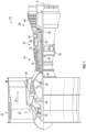
- FIG. 1 schematically illustrates a gas turbine engine 20.
- the gas turbine engine 20 is disclosed herein as a two-spool turbofan that generally incorporates a fan section 22, a compressor section 24, a combustor section 26 and a turbine section 28.
- Alternative engines might include an augmentor section (not shown) among other systems or features.
- the fan section 22 drives air along a bypass flow path B in a bypass duct, while the compressor section 24 drives air along a core flow path C for compression and communication into the combustor section 26 then expansion through the turbine section 28.
- the exemplary engine 20 generally includes a low speed spool 30 and a high speed spool 32 mounted for rotation about an engine central longitudinal axis A relative to an engine static structure 36 via several bearing systems 38. It should be understood that various bearing systems 38 at various locations may alternatively or additionally be provided, and the location of bearing systems 38 may be varied as appropriate to the application.
- the low speed spool 30 generally includes an inner shaft 40 that interconnects a fan 42, a low pressure compressor 44 and a low pressure turbine 46.
- the inner shaft 40 is connected to the fan 42 through a speed change mechanism, which in exemplary gas turbine engine 20 is illustrated as a geared architecture 48 to drive the fan 42 at a lower speed than the low speed spool 30.
- the high speed spool 32 includes an outer shaft 50 that interconnects a high pressure compressor 52 and high pressure turbine 54.
- a combustor 56 is arranged in exemplary gas turbine 20 between the high pressure compressor 52 and the high pressure turbine 54.
- An engine static structure 36 is arranged generally between the high pressure turbine 54 and the low pressure turbine 46.
- the engine static structure 36 further supports bearing systems 38 in the turbine section 28.
- the inner shaft 40 and the outer shaft 50 are concentric and rotate via bearing systems 38 about the engine central longitudinal axis A which is collinear with their longitudinal axes.
- each of the positions of the fan section 22, compressor section 24, combustor section 26, turbine section 28, and fan drive gear system 48 may be varied.
- gear system 48 may be located aft of combustor section 26 or even aft of turbine section 28, and fan section 22 may be positioned forward or aft of the location of gear system 48.
- the engine 20 in one example is a high-bypass geared aircraft engine.
- the engine 20 bypass ratio is greater than about six (6), with an example embodiment being greater than about ten (10)
- the geared architecture 48 is an epicyclic gear train, such as a planetary gear system or other gear system, with a gear reduction ratio of greater than about 2.3 and the low pressure turbine 46 has a pressure ratio that is greater than about five.
- the engine 20 bypass ratio is greater than about ten (10:1)
- the fan diameter is significantly larger than that of the low pressure compressor 44
- the low pressure turbine 46 has a pressure ratio that is greater than about five (5:1).
- Low pressure turbine 46 pressure ratio is pressure measured prior to inlet of low pressure turbine 46 as related to the pressure at the outlet of the low pressure turbine 46 prior to an exhaust nozzle.
- the geared architecture 48 may be an epicycle gear train, such as a planetary gear system or other gear system, with a gear reduction ratio of greater than about 2.3:1. It should be understood, however, that the above parameters are only exemplary of one embodiment of a geared architecture engine and that the present disclosure is applicable to other gas turbine engines including direct drive turbofans.
- the fan section 22 of the engine 20 is designed for a particular flight condition--typically cruise at about 0.8 Mach (270 m/sec) and about 35,000 feet (10,668 meters).
- TSFC Thrust Specific Fuel Consumption
- Low fan pressure ratio is the pressure ratio across the fan blade alone, without a Fan Exit Guide Vane (“FEGV”) system.
- the low fan pressure ratio as disclosed herein according to one non-limiting embodiment is less than about 1.45.
- "Low corrected fan tip speed” is the actual fan tip speed in ft/sec divided by an industry standard temperature correction of [(Tram °R)/(518.7 °R)] 0.5 ([(Tram °K)/(288 °K)] 0.5 .
- the "Low corrected fan tip speed” as disclosed herein according to one non-limiting embodiment is less than about 1150 ft/second (350.5 m/sec).
- discrete film cooling holes may be utilized in components in hot sections of a gas turbine engine 20.
- Discrete film cooling holes may result in uneven cooling as the areas immediately downstream from the cooling holes are cooler than the areas further away. Uneven cooling occurs due to the cool air mixing with hot air as the distance from the cooling hole exit increases.
- the uniformity of cooling can be affected by parameters such as spacing between cooling holes, turbulence in the cooling air flow, and other considerations. Inefficiency from uneven cooling requires more cooling air to be used than theoretically necessary. This decreases overall engine efficiency.
- Embodiments disclosed herein seek to improve uniformity of cooling thereby reducing the amount of air necessary for adequate cooling.
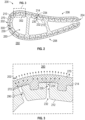
- FIG. 2 a cross-sectional view of a component 200 of the gas turbine engine 20 of FIG. 1 .
- the component is illustrated as an airfoil of a blade or a vane for the gas turbine engine 20.
- the component 200 shown in FIG. 2 is an example illustration of a possible component (e.g., an airfoil) that may be utilized with embodiments disclosed herein and thus the embodiments disclosed herein may be utilized with components other than an airfoil.
- the component 200 includes a leading edge 202, a trailing edge 204 opposite the leading edge 202, a pressure side 206, and a suction side 208 opposite the pressure side 206.
- the component 200 includes an interior compartment 250 and an exterior 260 (i.e. outside) of the component 200.
- the component 200 includes cooling holes 230 that fluidly connects the interior compartment 250 to the exterior 260 of the component 200.
- the component 200 includes a body portion 210 that encloses interior compartment 250.
- the body portion 210 includes an interior surface 212 defining the interior compartment 250 and an exterior surface 214 opposite the interior surface 202.
- the cooling holes 230 extend from an inlet 232 located on the interior surface 212 in the interior compartment 250 to an outlet 234 located on the exterior surface 214 of the component 200.
- the component 200 includes a porous mesh liner 270 fluidly connected to at least one of the cooling holes 230.
- the cooling holes 230 in operation direct cooling airflow from the interior compartment 250 of the component 200 into the porous mesh liner 270.
- the porous mesh liner 270 may at least partially enclose the exterior surface 214 of the component 200.
- the cooling holes 230 lead cooling air 290 from interior compartment 250 to the porous mesh liner 270 at the outlet 234 of the cooling hole 230.
- the porous mesh liner 270 may be a metal mesh, a composite matrix, a screen, a woven filter, a non-woven filter, a porous film, or a combination thereof.
- the porous mesh liner 270 may be composed of a metal, including but not limited to any metal that can be processed by spark plasma sintering, ceramics, cermets, ceramic matrix composites, metal matrix composites, carbides, hybrid composites, other materials currently available , or any combination thereof.
- the porous mesh liner 270 includes one or more torturous paths 272 leading from the outlet 234 of the cooling hole 230 toward the exterior 260 of the component 200.
- the porous mesh liner 270 may include a porous mesh design having an internal microstructure to diffuse the cooling air 290 and improve uniformity of cooling along the exterior surface 214 of the component 200.
- the porous mesh design helps evenly spread cooling airflow across the exterior surface and throughout the porous mesh liner 270 to improve uniformity of cooling.
- the porous mesh liner 270 is attached to the exterior surface 214 of the component 200.
- the porous mesh liner 270 may be attached to the exterior surface 214 via one or more attachment points 300 that are negative indentations that extend into the exterior surface 214, as shown in FIG. 2 .
- the attachment points 300 are located in the exterior surface 214 of the body portion 210.
- the attachment points 300 may be formed through the use of TOMO, additive manufacturing, or other advanced manufacturing system.
- TOMO refers to the Tomo Lithographic Molding (TLM) process developed by Mikro Systems, Inc. of Charlottesville, V.A. as described in patent US 9,879,861 B2 .
- the attachment point 300 includes protruding undercut portions 302 (e.g.
- the attachment points 300 may also increase the specific surface area for the adhesion between the porous mesh liner 270 and the exterior surface 214 of the component 200.
- the interface between the body portion 210 and the porous mesh liner 270 increases the adhesion of the porous mesh liner 270 to the body portion 210 thereby improving the durability and extending the useful life of the component 200.
- the ability of the porous mesh liner 270 to adapt to complex designs specific to the component 200 allows for the effective distribution and diffusion of the cooling air within the porous mesh liner 270.
- the resulting transpiration cooling can provide more uniform heat transfer and require less cooling air than traditional film cooling based only on discrete cooling holes.
- the improved cooling uniformity can decrease the amount of cooling air required and thus improves the efficiency and/or performance of the gas turbine engine 20.
- the more uniform cooling provided by the porous mesh liner 270 may also improve the performance, efficiency, and/or durability of the component 200. Efficiency improvements may also lead to emissions reductions and improved environmental impact. Furthermore, the improved cooling efficiency provided by the porous mesh liner 270 may negate the need for more complicated cooling path geometry inside the component 200, which can simplify the required ceramic core geometry during manufacturing of the body portion thereby increasing yields and decreasing cost compared to more difficult to produce cores and castings.
- a fabrication method is provided in which composite components that have a robust structure are formed by cast metal and detailed complex features (e.g., attachment points 300 of FIGs. 2 and 3 ) are formed by powdered metal.
- the fabrication method was developed by Mikro Systems, Inc. of Charlottesville, V.A. as described in U.S. patent application 16/023,879 filed on 06/29/2018 .
- a method of fabricating a composite component is provided.
- a component 200 is cast in an initial operation with one or more appropriate fabrication techniques.
- the component 200 may be a cast metal component.
- the component 200 has an exterior surface 214 and is formed to define attachment points 300.
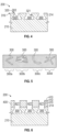
- each attachment point 300 extends inwardly relative to a body portion 210 of the component 200 from an uppermost portion 310 of the exterior surface 214 and, in accordance with embodiments, may have a dovetail-shaped cross-section. That is, each attachment point 300 has a relatively narrow neck section 320 at or proximate to the uppermost portion 310 of the exterior surface 214 and a tapered section 321.
- the tapered section 321 extends inwardly from the neck section 320 and has an increasing width with increasing depth from the neck section 320 and thus forms protruding undercut portions 302.
- the attachment points can have various cross-sectional shapes and sizes and that, while the following description generally relates to the dovetail-shape case, this is not required.
- the attachment points 300 can be provided as zig-zag attachment points 300a, spiral attachment points 300b, curved attachment points 300c, and multi-directional extrusion attachment points 300d.
- the attachment points 300 should have a shape that can securely maintain a cured sintered element (see FIGS. 8 and 9 ) therein.
- each of the openings 421 may have a more complex geometry than the attachment points 300 and, for example, they may have diameters that correspond to the diameters of the neck sections 320 (see FIG. 4 ) of the attachment points 300 and that may have protruding undercuts 302 or corrugations 410 along longitudinal axes thereof.
- the openings 421 are filled with powdered metallic materials 430 as shown in FIG. 7 .
- the powdered metallic materials 430 cured into sintered elements 432 and remainders of the one or more fugitive molds 400 are removed.
- the curing involves heating the component 200 and the powdered metallic materials to a temperature which is above the sintering temperature of the powdered metallic materials and below the melting point of the component 200. The heating continues until the powdered metallic materials are sufficiently densified and form the sintered elements 432.
- Each sintered element 432 has a cross-sectional shape which mimics the cross-sectional shapes of the attachment point 300 and the opening 421 it is formed in.
- each sintered element 432 has a first part 431 and a second part 434.
- the first part 431 is formed within the neck portion 320 and the tapered portion 321 of the corresponding attachment point 300.
- the second part 434 is integrally coupled to the first part 431 and extends from the first part 431 to protrude outwardly from the exterior surface 214.
- the corresponding attachment point 300 has a dovetail-shape and the corresponding opening 421 is corrugated, the first part 431 will have a corresponding dovetail-shape 310 and the second part 434 will have a corresponding corrugated shape 320.
- a final volume of each of the sintered elements 432 may be reduced from an initial volume of the powdered metallic material of the corresponding attachment point 300 and the corresponding opening 421.
- This volume reduction is a consequence of the curing process and may result in up to 15% reduction in volume. This can be seen in FIG. 9 in which the local edge 433 of the sintered element 432 is shown as having receded from the edge of the tapered section 321 of the corresponding attachment point 300.
- the cross-sectional shapes of the attachment points 300 are designed to secure the sintered elements 432.
- the diameter of the neck portion 320 should be sufficiently small as compared to the proximal portion of the tapered section 321 (see FIG. 4 ) so as to limit potential movement of the resulting sintered element 432 with the volume reduction having occurred.
- the securing of the sintered elements 432 in the attachment points 300 may be achieved by the use of fasteners to fasten the sintered elements 432 in the attachment points 300 or by the design or geometry of the attachment points 300 whereby the sintered elements 432 tighten into position even with the volume reduction occurring (see FIG. 10 ).
- the geometry of the attachment point 300 includes two or more attachment features 701 for a given sintered element 432.
- These attachment features 701 may be defined substantially opposite one another and may be designed such that the shrinkage of the sintered element 432 during the sintering thereof automatically results in a compression pressure being exerted between the sintered attachment protrusions 702 and the substrate material in and around the sintered attachment protrusions 702.
- the compression pressure serves to prevent the movement of the sintered element 432 with respect to the component 200 and may increase an effective heat transfer between the component 200 and the sintered element 432.
- the attachment features 701 may extend into the body portion 210 of the component 200 curvi-linearly outwardly such that the resulting sintered attachment protrusions 702 similarly extend into the component 200 curvi-linearly.
- the attachment features 701 taper away from each other with increasing depth into the component 200 and the sintered attachment protrusions 702 similarly taper away from each other with increasing depth into the component 200.
- Each attachment feature 701 and each corresponding sintered attachment protrusion 702 can have a substantially similar radius of outward curvature.
- Outer surfaces 7021 of the sintered attachment protrusions 702 may be nearly aligned in a radial dimension with an exterior surface 321 of the second part 434 and inner surfaces 7022 of the sintered attachment protrusions 702 may be separated from one another by a radial distance DR.
- the first and second parts 431 and 434 of the given sintered element 432 thus cooperatively form a tooth-root shaped element 710. While element 432 is shown to be a stand-alone feature, it can serve as a node that is connected to other similar nodes in a porous mesh.
- connection between nodes are similarly formed by powdered metal in a fugitive mold and may entail one or more flexures designed to withstand applicable shrinkage should the porous mesh be manufactured by a process such as spark plasma sintering.
- the size of and the spacing between the flexures can be engineered to control the porosity of the mesh.
- a separate porous mesh is attached to element 432 in a separate process.
- FIG. 11 shows a flow chart of method 900 of fabricating a component 200 for a gas turbine engine 20.
- a body portion 210 is manufactured by conventional investment casting, additive manufacturing, or other appropriate method.
- the body portion 210 encloses an interior compartment 250 of the component 200 and includes an interior surface 212 defining the interior compartment 250, an exterior surface 214 opposite the interior surface 212, an attachment point 300 on the exterior surface 214, and one or more cooling holes 230 within the body portion extending from the interior surface 212 to the exterior surface 214.
- a fugitive mold 400 defining an opening 421 is placed against the exterior surface 214 such that the opening 421 aligns with the attachment point 300.
- the opening 421 is filled with powdered metallic material 430.
- the component 200 and the powdered metallic material 430 is heated to a temperature above a sintering temperature of the powdered metallic material 430 and below a melting temperature of the component 200.
- heating the powdered metallic material 430 at block 810 forms the porous mesh liner 270.
- a porous mesh liner 270 is attached to the body portion 210 via the attachment point 300. As such, it should be seen that block 812 is an optional step that is not required for all embodiments of the disclosure.
- the porous mesh liner 270 at least partially encloses the exterior surface 214 of the body portion 210.
- the porous mesh liner 270 is fluidly connected to the one or more cooling holes 230.
- the cooling holes 230 in operation direct cooling airflow from the interior compartment 250 of the component 200 into the porous mesh liner 270.
- Benefits of the features described herein are the provision for production of a composite component that takes advantage of the beneficial properties of different manufacturing techniques and material systems.
- the fabrication methods can rely on a cast substrate for structural and creep resistance purposes and can use powdered metal features to create additional surface area or detailed geometry that could not be achievable with cast metal due to recrystallization, tooling costs or other limitations.
- tooling costs for a fugitive mold is significantly less than for a traditional wax pattern tool set. This allows for multiple different fugitive molds to be used on a single substrate thereby allowing numerous and varying designs to be produced and tested while requiring less tooling cost and time as compared to having to use different traditional tool sets. This can in turn allow for multiple complex designs to be built and tested for less cost than a single complex design, which is fabricated using conventional techniques and can result in faster innovations and a more valuable final product.
- inventions of the present disclosure include adhering a porous mesh to a substantially solid substrate to create a composite cast/porous metal turbine component to enable cooling of the metal turbine component by passing cooling air through the porous mesh liner.
Landscapes
- Engineering & Computer Science (AREA)
- Mechanical Engineering (AREA)
- Manufacturing & Machinery (AREA)
- General Engineering & Computer Science (AREA)
- Chemical & Material Sciences (AREA)
- Composite Materials (AREA)
- Materials Engineering (AREA)
- Physics & Mathematics (AREA)
- Fluid Mechanics (AREA)
- Architecture (AREA)
- Powder Metallurgy (AREA)
- Turbine Rotor Nozzle Sealing (AREA)
Claims (6)
- Bauteil (200) für ein Gasturbinentriebwerk (20), umfassend:einen Körperabschnitt (210), der ein Innenfach (250) des Bauteils umschließt, wobei der Körperabschnitt eine Innenfläche (212), die das Innenfach definiert, eine der Innenfläche gegenüberliegende Außenfläche (214) und ein oder mehrere Kühllöcher (230) innerhalb des Körperabschnitts beinhaltet, wobei sich jedes des einen oder der mehreren Kühllöcher von der Innenfläche zur Außenfläche erstreckt;eine poröse Netzauskleidung (270), die die Außenfläche des Körperabschnitts zumindest teilweise umschließt, wobei die poröse Netzauskleidung mit dem einen oder den mehreren Kühllöchern in Fluidverbindung steht,wobei die Kühllöcher im Betrieb einen Kühlluftstrom aus dem Innenraum des Bauteils in die poröse Netzauskleidung leiten; undeinen Befestigungspunkt (300), der sich in der Außenfläche des Körperabschnitts befindet, wobei die poröse Netzauskleidung über den Befestigungspunkt an der Außenfläche des Körperabschnitts befestigt ist,wobei sich der Befestigungspunkt in die Außenfläche des Körperabschnitts erstreckt, dadurch gekennzeichnet, dassder Befestigungspunkt einen vorstehenden hinterschnittenen Abschnitt (302) beinhaltet,wobei der Befestigungspunkt einen Halsabschnitt (320) an der Außenfläche (214) oder in der Nähe eines obersten Abschnitts (310) der Außenfläche (214) beinhaltet, undwobei der Befestigungspunkt einen konischen Abschnitt (321) beinhaltet, der konische Abschnitt (321) sich von dem Halsabschnitt (320) nach innen erstreckt und mit zunehmender Tiefe von dem Halsabschnitt (320) eine zunehmende Breite aufweist, um den vorstehenden hinterschnittenen Abschnitt (302) zu bilden.
- Bauteil (200) nach Anspruch 1, wobei das Bauteil eine Schaufel für das Gasturbinentriebwerk (20) ist, oder
wobei das Bauteil eine Leitschaufel für das Gasturbinentriebwerk ist. - Bauteil (200) nach Anspruch 1 oder 2, wobei die poröse Netzauskleidung (270) eine Metallgeflechtauskleidung ist, oder wobei die poröse Netzauskleidung eine Verbundstoffmatrix ist.
- Bauteil (200) nach Anspruch 1, 2 oder 3, wobei die poröse Netzauskleidung (270) einen oder mehrere gewundene Pfade (272) aufweist, die von einem Auslass (234) des Kühllochs (230) zu der Außenseite des Bauteils führen.
- Verfahren (900) zum Herstellen eines Bauteils (200) eines Gasturbinentriebwerks (20), wobei das Verfahren umfasst:Fertigen eines Körperabschnitts (210), der ein Innenfach (250) des Bauteils umschließt, wobei der Körperabschnitt eine Innenfläche (212), die das Innenfach definiert, eine der Innenfläche gegenüberliegende Außenfläche (214), einen Befestigungspunkt (300) auf der Außenfläche und ein oder mehrere Kühllöcher (230) innerhalb des Körperabschnitts beinhaltet, wobei sich jedes des einen oder der mehreren Kühllöcher von der Innenfläche zu der Außenfläche erstreckt;Platzieren einer flüchtigen Form (400), die eine Öffnung (421) definiert, gegen die Außenfläche, so dass die Öffnung mit dem Befestigungspunkt fluchtet;Füllen der Öffnung mit pulverförmigem Metallmaterial;Erwärmen der gegossenen Metallbauteils und des pulverförmigen Metallmaterials auf eine Temperatur über einer Sintertemperatur des pulverförmigen Metallmaterials und unter einer Schmelztemperatur des Bauteils; undAnbringen einer porösen Netzauskleidung (270) an dem Körperabschnitt über dem Befestigungspunkt, wobei die poröse Netzauskleidung die Außenfläche des Körperabschnitts zumindest teilweise umschließt,wobei die poröse Netzauskleidung mit dem einen oder den mehreren Kühllöchern in Fluidverbindung steht,wobei die Kühllöcher im Betrieb einen Kühlluftstrom aus dem Innenraum des Bauteils in die poröse Netzauskleidung leiten,wobei sich der Befestigungspunkt in die Außenfläche des Körperabschnitts erstreckt,wobei das Bauteil (200) eine Lauf- oder Leitschaufel für das Gasturbinentriebwerk (20) ist,wobei die poröse Netzauskleidung (270) eine Metallgeflechtauskleidung oder eine Verbundstoffmatrix ist,wobei die poröse Netzauskleidung (270) einen oder mehrere gewundene Pfade (272) beinhaltet, die von einem Auslass (234) des Kühllochs (230) zu der Außenseite des Bauteils (200) führen,dadurch gekennzeichnet, dass der Befestigungspunkt einen vorstehenden hinterschnittenen Abschnitt (302) beinhaltet,wobei der Befestigungspunkt einen Halsabschnitt (320) an der Außenfläche (214) oder in der Nähe eines obersten Abschnitts (310) der Außenfläche (214) beinhaltet, undwobei der Befestigungspunkt einen konischen Abschnitt (321) beinhaltet, der konische Abschnitt (321) sich von dem Halsabschnitt (320) nach innen erstreckt und mit zunehmender Tiefe von dem Halsabschnitt (320) eine zunehmende Breite aufweist, um den vorstehenden hinterschnittenen Abschnitt (302) zu bilden.
- Verfahren zum Herstellen eines Bauteils (200) für ein Gasturbinentriebwerk (20), wobei das Verfahren umfasst:Fertigen eines Körperabschnitts (210), der ein Innenfach (250) des Bauteils umschließt, wobei der Körperabschnitt eine Innenfläche (212), die das Innenfach definiert, eine der Innenfläche gegenüberliegende Außenfläche (214), einen Befestigungspunkt (300) auf der Außenfläche und ein oder mehrere Kühllöcher (230) innerhalb des Körperabschnitts beinhaltet,wobei sich jedes des einen oder der mehreren Kühllöcher von der Innenfläche zu der Außenfläche erstreckt;Platzieren einer flüchtigen Form (400), die eine Öffnung (421) definiert, gegen die Außenfläche, so dass die Öffnung mit dem Befestigungspunkt fluchtet;Füllen der Öffnung mit pulverförmigem Metallmaterial; undErwärmen des gegossenen Metallbauteils und des pulverförmigen Metallmaterials auf eine Temperatur über einer Sintertemperatur des pulverförmigen Metallmaterials und unter einer Schmelztemperatur des Bauteils,wobei eine poröse Netzauskleidung (270) aus dem pulverförmigen Metallmaterial gebildet und über den Befestigungspunkt an dem Körperabschnitt befestigt wird, wobei die poröse Netzauskleidung die Außenfläche des Körperabschnitts zumindest teilweise umschließt,wobei die poröse Netzauskleidung mit einem oder mehreren Kühllöchern in Fluidverbindung steht, die im Betrieb den Kühlluftstrom aus dem Innenraum des Bauteils in die poröse Netzauskleidung leiten,wobei sich der Befestigungspunkt in die Außenfläche des Körperabschnitts erstreckt, dadurch gekennzeichnet, dass der Befestigungspunkt einen vorstehenden hinterschnittenen Abschnitt (302) beinhaltet,wobei der Befestigungspunkt einen Halsabschnitt (320) an der Außenfläche (214) oder in der Nähe eines obersten Abschnitts (310) der Außenfläche (214) beinhaltet, undwobei der Befestigungspunkt einen konischen Abschnitt (321) beinhaltet, der konische Abschnitt (321) sich von dem Halsabschnitt (320) nach innen erstreckt und mit zunehmender Tiefe von dem Halsabschnitt (320) eine zunehmende Breite aufweist, um den vorstehenden hinterschnittenen Abschnitt (302) zu bilden.
Applications Claiming Priority (1)
| Application Number | Priority Date | Filing Date | Title |
|---|---|---|---|
| US16/152,522 US20200109635A1 (en) | 2018-10-05 | 2018-10-05 | Composite cast porous metal turbine component |
Publications (2)
| Publication Number | Publication Date |
|---|---|
| EP3633148A1 EP3633148A1 (de) | 2020-04-08 |
| EP3633148B1 true EP3633148B1 (de) | 2023-08-09 |
Family
ID=68172113
Family Applications (1)
| Application Number | Title | Priority Date | Filing Date |
|---|---|---|---|
| EP19201715.0A Active EP3633148B1 (de) | 2018-10-05 | 2019-10-07 | Poröses metallisches turbinenbauteil aus verbundguss und entsprechende herstellungsverfahren |
Country Status (2)
| Country | Link |
|---|---|
| US (1) | US20200109635A1 (de) |
| EP (1) | EP3633148B1 (de) |
Families Citing this family (1)
| Publication number | Priority date | Publication date | Assignee | Title |
|---|---|---|---|---|
| EP3991883A1 (de) * | 2020-10-27 | 2022-05-04 | Safran | Verfahren zur herstellung einer leitschaufel für ein turbotriebwerk |
Family Cites Families (10)
| Publication number | Priority date | Publication date | Assignee | Title |
|---|---|---|---|---|
| GB1299904A (en) * | 1969-12-30 | 1972-12-13 | Curtiss Wright Corp | Transpiration cooled turbine blade with thin trailing edge |
| US3644060A (en) * | 1970-06-05 | 1972-02-22 | John K Bryan | Cooled airfoil |
| US5236151A (en) * | 1991-12-23 | 1993-08-17 | General Electric Company | Thermal barrier structure |
| US6224339B1 (en) * | 1998-07-08 | 2001-05-01 | Allison Advanced Development Company | High temperature airfoil |
| US7144220B2 (en) * | 2004-07-30 | 2006-12-05 | United Technologies Corporation | Investment casting |
| US7828515B1 (en) * | 2009-05-19 | 2010-11-09 | Florida Turbine Technologies, Inc. | Multiple piece turbine airfoil |
| US9879861B2 (en) | 2013-03-15 | 2018-01-30 | Rolls-Royce Corporation | Gas turbine engine with improved combustion liner |
| JP6529243B2 (ja) * | 2014-11-17 | 2019-06-12 | 三菱日立パワーシステムズ株式会社 | ガスタービン構成部材及びガスタービン |
| US10598026B2 (en) * | 2016-05-12 | 2020-03-24 | General Electric Company | Engine component wall with a cooling circuit |
| US20180111200A1 (en) * | 2016-10-20 | 2018-04-26 | General Electric Company | Porous film hole exit and method for making same |
-
2018
- 2018-10-05 US US16/152,522 patent/US20200109635A1/en not_active Abandoned
-
2019
- 2019-10-07 EP EP19201715.0A patent/EP3633148B1/de active Active
Also Published As
| Publication number | Publication date |
|---|---|
| EP3633148A1 (de) | 2020-04-08 |
| US20200109635A1 (en) | 2020-04-09 |
Similar Documents
| Publication | Publication Date | Title |
|---|---|---|
| EP3056674B1 (de) | Artikel mit kühlkanal mit wellenförmigem profil | |
| EP3084182B1 (de) | Kühlhohlraum für gasturbinenmotorkomponente wirbelstimulierender funktion | |
| US11624322B2 (en) | Hourglass airfoil cooling configuration | |
| CN110735665B (zh) | 具有可调节冷却构造的翼型件 | |
| JP6888946B2 (ja) | 格子構造を使用する、内部通路を有する部品を形成する方法及びアセンブリ | |
| US20190176228A1 (en) | Gas turbine engine component cooling passage and space eating core | |
| US10024181B2 (en) | Casting of thin wall hollow airfoil sections | |
| WO2014175940A2 (en) | Gas turbine engine component manufacturing method and core for making same | |
| EP3633148B1 (de) | Poröses metallisches turbinenbauteil aus verbundguss und entsprechende herstellungsverfahren | |
| EP3693547B1 (de) | Gasturbinentriebwerksschaufel, gasturbinentriebwerk und verfahren zur herstellung einer gasturbinentriebwerksschaufel | |
| US11905854B2 (en) | Two-piece baffle | |
| JP2017140650A (ja) | 格子構造物を使用して内部通路を有する部品を形成するための方法及びアセンブリ | |
| EP3412868A1 (de) | Plattformkühlung mit einstellbarer durchflussteilung für einen gasturbinenmotor | |
| EP3748133B1 (de) | Ermüdungsbeständige schaufelaussenluftdichtung | |
| EP2929955B1 (de) | Buckelrippensystem | |
| EP4431701A1 (de) | Verfahren zur anpassung der vibratorischen eigenschaften einer abdeckung für eine hohlschaufelanordnung mit offenem körper, hohlschaufelanordnung, und verfahren zur änderung einer vibratorischen eigenschaft einer abdeckung an einen offenen körper |
Legal Events
| Date | Code | Title | Description |
|---|---|---|---|
| PUAI | Public reference made under article 153(3) epc to a published international application that has entered the european phase |
Free format text: ORIGINAL CODE: 0009012 |
|
| STAA | Information on the status of an ep patent application or granted ep patent |
Free format text: STATUS: THE APPLICATION HAS BEEN PUBLISHED |
|
| AK | Designated contracting states |
Kind code of ref document: A1 Designated state(s): AL AT BE BG CH CY CZ DE DK EE ES FI FR GB GR HR HU IE IS IT LI LT LU LV MC MK MT NL NO PL PT RO RS SE SI SK SM TR |
|
| AX | Request for extension of the european patent |
Extension state: BA ME |
|
| STAA | Information on the status of an ep patent application or granted ep patent |
Free format text: STATUS: REQUEST FOR EXAMINATION WAS MADE |
|
| 17P | Request for examination filed |
Effective date: 20201007 |
|
| RBV | Designated contracting states (corrected) |
Designated state(s): AL AT BE BG CH CY CZ DE DK EE ES FI FR GB GR HR HU IE IS IT LI LT LU LV MC MK MT NL NO PL PT RO RS SE SI SK SM TR |
|
| RAP1 | Party data changed (applicant data changed or rights of an application transferred) |
Owner name: RAYTHEON TECHNOLOGIES CORPORATION |
|
| STAA | Information on the status of an ep patent application or granted ep patent |
Free format text: STATUS: EXAMINATION IS IN PROGRESS |
|
| 17Q | First examination report despatched |
Effective date: 20210406 |
|
| GRAP | Despatch of communication of intention to grant a patent |
Free format text: ORIGINAL CODE: EPIDOSNIGR1 |
|
| STAA | Information on the status of an ep patent application or granted ep patent |
Free format text: STATUS: GRANT OF PATENT IS INTENDED |
|
| INTG | Intention to grant announced |
Effective date: 20220902 |
|
| GRAJ | Information related to disapproval of communication of intention to grant by the applicant or resumption of examination proceedings by the epo deleted |
Free format text: ORIGINAL CODE: EPIDOSDIGR1 |
|
| STAA | Information on the status of an ep patent application or granted ep patent |
Free format text: STATUS: EXAMINATION IS IN PROGRESS |
|
| INTC | Intention to grant announced (deleted) | ||
| GRAP | Despatch of communication of intention to grant a patent |
Free format text: ORIGINAL CODE: EPIDOSNIGR1 |
|
| STAA | Information on the status of an ep patent application or granted ep patent |
Free format text: STATUS: GRANT OF PATENT IS INTENDED |
|
| INTG | Intention to grant announced |
Effective date: 20230223 |
|
| GRAS | Grant fee paid |
Free format text: ORIGINAL CODE: EPIDOSNIGR3 |
|
| GRAA | (expected) grant |
Free format text: ORIGINAL CODE: 0009210 |
|
| STAA | Information on the status of an ep patent application or granted ep patent |
Free format text: STATUS: THE PATENT HAS BEEN GRANTED |
|
| AK | Designated contracting states |
Kind code of ref document: B1 Designated state(s): AL AT BE BG CH CY CZ DE DK EE ES FI FR GB GR HR HU IE IS IT LI LT LU LV MC MK MT NL NO PL PT RO RS SE SI SK SM TR |
|
| REG | Reference to a national code |
Ref country code: GB Ref legal event code: FG4D |
|
| REG | Reference to a national code |
Ref country code: CH Ref legal event code: EP |
|
| REG | Reference to a national code |
Ref country code: DE Ref legal event code: R096 Ref document number: 602019034442 Country of ref document: DE |
|
| REG | Reference to a national code |
Ref country code: IE Ref legal event code: FG4D |
|
| RAP4 | Party data changed (patent owner data changed or rights of a patent transferred) |
Owner name: RTX CORPORATION |
|
| REG | Reference to a national code |
Ref country code: LT Ref legal event code: MG9D |
|
| REG | Reference to a national code |
Ref country code: NL Ref legal event code: MP Effective date: 20230809 |
|
| REG | Reference to a national code |
Ref country code: AT Ref legal event code: MK05 Ref document number: 1597746 Country of ref document: AT Kind code of ref document: T Effective date: 20230809 |
|
| PG25 | Lapsed in a contracting state [announced via postgrant information from national office to epo] |
Ref country code: GR Free format text: LAPSE BECAUSE OF FAILURE TO SUBMIT A TRANSLATION OF THE DESCRIPTION OR TO PAY THE FEE WITHIN THE PRESCRIBED TIME-LIMIT Effective date: 20231110 |
|
| PG25 | Lapsed in a contracting state [announced via postgrant information from national office to epo] |
Ref country code: IS Free format text: LAPSE BECAUSE OF FAILURE TO SUBMIT A TRANSLATION OF THE DESCRIPTION OR TO PAY THE FEE WITHIN THE PRESCRIBED TIME-LIMIT Effective date: 20231209 |
|
| PG25 | Lapsed in a contracting state [announced via postgrant information from national office to epo] |
Ref country code: SE Free format text: LAPSE BECAUSE OF FAILURE TO SUBMIT A TRANSLATION OF THE DESCRIPTION OR TO PAY THE FEE WITHIN THE PRESCRIBED TIME-LIMIT Effective date: 20230809 Ref country code: RS Free format text: LAPSE BECAUSE OF FAILURE TO SUBMIT A TRANSLATION OF THE DESCRIPTION OR TO PAY THE FEE WITHIN THE PRESCRIBED TIME-LIMIT Effective date: 20230809 Ref country code: PT Free format text: LAPSE BECAUSE OF FAILURE TO SUBMIT A TRANSLATION OF THE DESCRIPTION OR TO PAY THE FEE WITHIN THE PRESCRIBED TIME-LIMIT Effective date: 20231211 Ref country code: NO Free format text: LAPSE BECAUSE OF FAILURE TO SUBMIT A TRANSLATION OF THE DESCRIPTION OR TO PAY THE FEE WITHIN THE PRESCRIBED TIME-LIMIT Effective date: 20231109 Ref country code: NL Free format text: LAPSE BECAUSE OF FAILURE TO SUBMIT A TRANSLATION OF THE DESCRIPTION OR TO PAY THE FEE WITHIN THE PRESCRIBED TIME-LIMIT Effective date: 20230809 Ref country code: LV Free format text: LAPSE BECAUSE OF FAILURE TO SUBMIT A TRANSLATION OF THE DESCRIPTION OR TO PAY THE FEE WITHIN THE PRESCRIBED TIME-LIMIT Effective date: 20230809 Ref country code: LT Free format text: LAPSE BECAUSE OF FAILURE TO SUBMIT A TRANSLATION OF THE DESCRIPTION OR TO PAY THE FEE WITHIN THE PRESCRIBED TIME-LIMIT Effective date: 20230809 Ref country code: IS Free format text: LAPSE BECAUSE OF FAILURE TO SUBMIT A TRANSLATION OF THE DESCRIPTION OR TO PAY THE FEE WITHIN THE PRESCRIBED TIME-LIMIT Effective date: 20231209 Ref country code: HR Free format text: LAPSE BECAUSE OF FAILURE TO SUBMIT A TRANSLATION OF THE DESCRIPTION OR TO PAY THE FEE WITHIN THE PRESCRIBED TIME-LIMIT Effective date: 20230809 Ref country code: GR Free format text: LAPSE BECAUSE OF FAILURE TO SUBMIT A TRANSLATION OF THE DESCRIPTION OR TO PAY THE FEE WITHIN THE PRESCRIBED TIME-LIMIT Effective date: 20231110 Ref country code: FI Free format text: LAPSE BECAUSE OF FAILURE TO SUBMIT A TRANSLATION OF THE DESCRIPTION OR TO PAY THE FEE WITHIN THE PRESCRIBED TIME-LIMIT Effective date: 20230809 Ref country code: AT Free format text: LAPSE BECAUSE OF FAILURE TO SUBMIT A TRANSLATION OF THE DESCRIPTION OR TO PAY THE FEE WITHIN THE PRESCRIBED TIME-LIMIT Effective date: 20230809 |
|
| PG25 | Lapsed in a contracting state [announced via postgrant information from national office to epo] |
Ref country code: PL Free format text: LAPSE BECAUSE OF FAILURE TO SUBMIT A TRANSLATION OF THE DESCRIPTION OR TO PAY THE FEE WITHIN THE PRESCRIBED TIME-LIMIT Effective date: 20230809 |
|
| PG25 | Lapsed in a contracting state [announced via postgrant information from national office to epo] |
Ref country code: ES Free format text: LAPSE BECAUSE OF FAILURE TO SUBMIT A TRANSLATION OF THE DESCRIPTION OR TO PAY THE FEE WITHIN THE PRESCRIBED TIME-LIMIT Effective date: 20230809 |
|
| PG25 | Lapsed in a contracting state [announced via postgrant information from national office to epo] |
Ref country code: SM Free format text: LAPSE BECAUSE OF FAILURE TO SUBMIT A TRANSLATION OF THE DESCRIPTION OR TO PAY THE FEE WITHIN THE PRESCRIBED TIME-LIMIT Effective date: 20230809 Ref country code: RO Free format text: LAPSE BECAUSE OF FAILURE TO SUBMIT A TRANSLATION OF THE DESCRIPTION OR TO PAY THE FEE WITHIN THE PRESCRIBED TIME-LIMIT Effective date: 20230809 Ref country code: ES Free format text: LAPSE BECAUSE OF FAILURE TO SUBMIT A TRANSLATION OF THE DESCRIPTION OR TO PAY THE FEE WITHIN THE PRESCRIBED TIME-LIMIT Effective date: 20230809 Ref country code: EE Free format text: LAPSE BECAUSE OF FAILURE TO SUBMIT A TRANSLATION OF THE DESCRIPTION OR TO PAY THE FEE WITHIN THE PRESCRIBED TIME-LIMIT Effective date: 20230809 Ref country code: DK Free format text: LAPSE BECAUSE OF FAILURE TO SUBMIT A TRANSLATION OF THE DESCRIPTION OR TO PAY THE FEE WITHIN THE PRESCRIBED TIME-LIMIT Effective date: 20230809 Ref country code: CZ Free format text: LAPSE BECAUSE OF FAILURE TO SUBMIT A TRANSLATION OF THE DESCRIPTION OR TO PAY THE FEE WITHIN THE PRESCRIBED TIME-LIMIT Effective date: 20230809 Ref country code: SK Free format text: LAPSE BECAUSE OF FAILURE TO SUBMIT A TRANSLATION OF THE DESCRIPTION OR TO PAY THE FEE WITHIN THE PRESCRIBED TIME-LIMIT Effective date: 20230809 |
|
| REG | Reference to a national code |
Ref country code: DE Ref legal event code: R097 Ref document number: 602019034442 Country of ref document: DE |
|
| PG25 | Lapsed in a contracting state [announced via postgrant information from national office to epo] |
Ref country code: IT Free format text: LAPSE BECAUSE OF FAILURE TO SUBMIT A TRANSLATION OF THE DESCRIPTION OR TO PAY THE FEE WITHIN THE PRESCRIBED TIME-LIMIT Effective date: 20230809 Ref country code: MC Free format text: LAPSE BECAUSE OF FAILURE TO SUBMIT A TRANSLATION OF THE DESCRIPTION OR TO PAY THE FEE WITHIN THE PRESCRIBED TIME-LIMIT Effective date: 20230809 |
|
| REG | Reference to a national code |
Ref country code: CH Ref legal event code: PL |
|
| PLBE | No opposition filed within time limit |
Free format text: ORIGINAL CODE: 0009261 |
|
| STAA | Information on the status of an ep patent application or granted ep patent |
Free format text: STATUS: NO OPPOSITION FILED WITHIN TIME LIMIT |
|
| REG | Reference to a national code |
Ref country code: BE Ref legal event code: MM Effective date: 20231031 |
|
| PG25 | Lapsed in a contracting state [announced via postgrant information from national office to epo] |
Ref country code: LU Free format text: LAPSE BECAUSE OF NON-PAYMENT OF DUE FEES Effective date: 20231007 |
|
| PG25 | Lapsed in a contracting state [announced via postgrant information from national office to epo] |
Ref country code: LU Free format text: LAPSE BECAUSE OF NON-PAYMENT OF DUE FEES Effective date: 20231007 |
|
| 26N | No opposition filed |
Effective date: 20240513 |
|
| PG25 | Lapsed in a contracting state [announced via postgrant information from national office to epo] |
Ref country code: CH Free format text: LAPSE BECAUSE OF NON-PAYMENT OF DUE FEES Effective date: 20231031 |
|
| PG25 | Lapsed in a contracting state [announced via postgrant information from national office to epo] |
Ref country code: CH Free format text: LAPSE BECAUSE OF NON-PAYMENT OF DUE FEES Effective date: 20231031 Ref country code: SI Free format text: LAPSE BECAUSE OF FAILURE TO SUBMIT A TRANSLATION OF THE DESCRIPTION OR TO PAY THE FEE WITHIN THE PRESCRIBED TIME-LIMIT Effective date: 20230809 |
|
| PG25 | Lapsed in a contracting state [announced via postgrant information from national office to epo] |
Ref country code: BE Free format text: LAPSE BECAUSE OF NON-PAYMENT OF DUE FEES Effective date: 20231031 |
|
| PG25 | Lapsed in a contracting state [announced via postgrant information from national office to epo] |
Ref country code: IE Free format text: LAPSE BECAUSE OF NON-PAYMENT OF DUE FEES Effective date: 20231007 |
|
| PG25 | Lapsed in a contracting state [announced via postgrant information from national office to epo] |
Ref country code: IE Free format text: LAPSE BECAUSE OF NON-PAYMENT OF DUE FEES Effective date: 20231007 |
|
| PG25 | Lapsed in a contracting state [announced via postgrant information from national office to epo] |
Ref country code: BG Free format text: LAPSE BECAUSE OF FAILURE TO SUBMIT A TRANSLATION OF THE DESCRIPTION OR TO PAY THE FEE WITHIN THE PRESCRIBED TIME-LIMIT Effective date: 20230809 |
|
| PG25 | Lapsed in a contracting state [announced via postgrant information from national office to epo] |
Ref country code: BG Free format text: LAPSE BECAUSE OF FAILURE TO SUBMIT A TRANSLATION OF THE DESCRIPTION OR TO PAY THE FEE WITHIN THE PRESCRIBED TIME-LIMIT Effective date: 20230809 |
|
| PG25 | Lapsed in a contracting state [announced via postgrant information from national office to epo] |
Ref country code: CY Free format text: LAPSE BECAUSE OF FAILURE TO SUBMIT A TRANSLATION OF THE DESCRIPTION OR TO PAY THE FEE WITHIN THE PRESCRIBED TIME-LIMIT; INVALID AB INITIO Effective date: 20191007 |
|
| PG25 | Lapsed in a contracting state [announced via postgrant information from national office to epo] |
Ref country code: HU Free format text: LAPSE BECAUSE OF FAILURE TO SUBMIT A TRANSLATION OF THE DESCRIPTION OR TO PAY THE FEE WITHIN THE PRESCRIBED TIME-LIMIT; INVALID AB INITIO Effective date: 20191007 |
|
| REG | Reference to a national code |
Ref country code: DE Ref legal event code: R081 Ref document number: 602019034442 Country of ref document: DE Owner name: RTX CORPORATION (N.D.GES.D. STAATES DELAWARE),, US Free format text: FORMER OWNER: RAYTHEON TECHNOLOGIES CORPORATION, FARMINGTON, CT, US |
|
| PGFP | Annual fee paid to national office [announced via postgrant information from national office to epo] |
Ref country code: GB Payment date: 20250923 Year of fee payment: 7 |
|
| PGFP | Annual fee paid to national office [announced via postgrant information from national office to epo] |
Ref country code: FR Payment date: 20250924 Year of fee payment: 7 |
|
| PG25 | Lapsed in a contracting state [announced via postgrant information from national office to epo] |
Ref country code: TR Free format text: LAPSE BECAUSE OF FAILURE TO SUBMIT A TRANSLATION OF THE DESCRIPTION OR TO PAY THE FEE WITHIN THE PRESCRIBED TIME-LIMIT Effective date: 20230809 |
|
| PGFP | Annual fee paid to national office [announced via postgrant information from national office to epo] |
Ref country code: DE Payment date: 20250923 Year of fee payment: 7 |
|
| P01 | Opt-out of the competence of the unified patent court (upc) registered |
Free format text: CASE NUMBER: UPC_APP_0019205_3633148/2025 Effective date: 20251223 |