EP3633160A2 - Moteur de turbine à gaz avec acumulateur d'énergie intégré - Google Patents
Moteur de turbine à gaz avec acumulateur d'énergie intégré Download PDFInfo
- Publication number
- EP3633160A2 EP3633160A2 EP19196505.2A EP19196505A EP3633160A2 EP 3633160 A2 EP3633160 A2 EP 3633160A2 EP 19196505 A EP19196505 A EP 19196505A EP 3633160 A2 EP3633160 A2 EP 3633160A2
- Authority
- EP
- European Patent Office
- Prior art keywords
- gas turbine
- turbine engine
- compressor
- engine according
- electric machine
- Prior art date
- Legal status (The legal status is an assumption and is not a legal conclusion. Google has not performed a legal analysis and makes no representation as to the accuracy of the status listed.)
- Granted
Links
Images




Classifications
-
- F—MECHANICAL ENGINEERING; LIGHTING; HEATING; WEAPONS; BLASTING
- F02—COMBUSTION ENGINES; HOT-GAS OR COMBUSTION-PRODUCT ENGINE PLANTS
- F02K—JET-PROPULSION PLANTS
- F02K3/00—Plants including a gas turbine driving a compressor or a ducted fan
- F02K3/02—Plants including a gas turbine driving a compressor or a ducted fan in which part of the working fluid by-passes the turbine and combustion chamber
- F02K3/04—Plants including a gas turbine driving a compressor or a ducted fan in which part of the working fluid by-passes the turbine and combustion chamber the plant including ducted fans, i.e. fans with high volume, low pressure outputs, for augmenting the jet thrust, e.g. of double-flow type
- F02K3/075—Plants including a gas turbine driving a compressor or a ducted fan in which part of the working fluid by-passes the turbine and combustion chamber the plant including ducted fans, i.e. fans with high volume, low pressure outputs, for augmenting the jet thrust, e.g. of double-flow type controlling flow ratio between flows
-
- F—MECHANICAL ENGINEERING; LIGHTING; HEATING; WEAPONS; BLASTING
- F01—MACHINES OR ENGINES IN GENERAL; ENGINE PLANTS IN GENERAL; STEAM ENGINES
- F01D—NON-POSITIVE DISPLACEMENT MACHINES OR ENGINES, e.g. STEAM TURBINES
- F01D15/00—Adaptations of machines or engines for special use; Combinations of engines with devices driven thereby
- F01D15/10—Adaptations for driving, or combinations with, electric generators
-
- F—MECHANICAL ENGINEERING; LIGHTING; HEATING; WEAPONS; BLASTING
- F02—COMBUSTION ENGINES; HOT-GAS OR COMBUSTION-PRODUCT ENGINE PLANTS
- F02C—GAS-TURBINE PLANTS; AIR INTAKES FOR JET-PROPULSION PLANTS; CONTROLLING FUEL SUPPLY IN AIR-BREATHING JET-PROPULSION PLANTS
- F02C3/00—Gas-turbine plants characterised by the use of combustion products as the working fluid
- F02C3/04—Gas-turbine plants characterised by the use of combustion products as the working fluid having a turbine driving a compressor
- F02C3/107—Gas-turbine plants characterised by the use of combustion products as the working fluid having a turbine driving a compressor with two or more rotors connected by power transmission
- F02C3/113—Gas-turbine plants characterised by the use of combustion products as the working fluid having a turbine driving a compressor with two or more rotors connected by power transmission with variable power transmission between rotors
-
- F—MECHANICAL ENGINEERING; LIGHTING; HEATING; WEAPONS; BLASTING
- F02—COMBUSTION ENGINES; HOT-GAS OR COMBUSTION-PRODUCT ENGINE PLANTS
- F02C—GAS-TURBINE PLANTS; AIR INTAKES FOR JET-PROPULSION PLANTS; CONTROLLING FUEL SUPPLY IN AIR-BREATHING JET-PROPULSION PLANTS
- F02C6/00—Plural gas-turbine plants; Combinations of gas-turbine plants with other apparatus; Adaptations of gas-turbine plants for special use
- F02C6/14—Gas-turbine plants having means for storing energy, e.g. for meeting peak loads
-
- F—MECHANICAL ENGINEERING; LIGHTING; HEATING; WEAPONS; BLASTING
- F02—COMBUSTION ENGINES; HOT-GAS OR COMBUSTION-PRODUCT ENGINE PLANTS
- F02C—GAS-TURBINE PLANTS; AIR INTAKES FOR JET-PROPULSION PLANTS; CONTROLLING FUEL SUPPLY IN AIR-BREATHING JET-PROPULSION PLANTS
- F02C7/00—Features, components parts, details or accessories, not provided for in, or of interest apart form groups F02C1/00 - F02C6/00; Air intakes for jet-propulsion plants
- F02C7/32—Arrangement, mounting, or driving, of auxiliaries
-
- F—MECHANICAL ENGINEERING; LIGHTING; HEATING; WEAPONS; BLASTING
- F05—INDEXING SCHEMES RELATING TO ENGINES OR PUMPS IN VARIOUS SUBCLASSES OF CLASSES F01-F04
- F05D—INDEXING SCHEME FOR ASPECTS RELATING TO NON-POSITIVE-DISPLACEMENT MACHINES OR ENGINES, GAS-TURBINES OR JET-PROPULSION PLANTS
- F05D2220/00—Application
- F05D2220/30—Application in turbines
- F05D2220/32—Application in turbines in gas turbines
-
- F—MECHANICAL ENGINEERING; LIGHTING; HEATING; WEAPONS; BLASTING
- F05—INDEXING SCHEMES RELATING TO ENGINES OR PUMPS IN VARIOUS SUBCLASSES OF CLASSES F01-F04
- F05D—INDEXING SCHEME FOR ASPECTS RELATING TO NON-POSITIVE-DISPLACEMENT MACHINES OR ENGINES, GAS-TURBINES OR JET-PROPULSION PLANTS
- F05D2220/00—Application
- F05D2220/30—Application in turbines
- F05D2220/32—Application in turbines in gas turbines
- F05D2220/321—Application in turbines in gas turbines for a special turbine stage
- F05D2220/3216—Application in turbines in gas turbines for a special turbine stage for a special compressor stage
-
- F—MECHANICAL ENGINEERING; LIGHTING; HEATING; WEAPONS; BLASTING
- F05—INDEXING SCHEMES RELATING TO ENGINES OR PUMPS IN VARIOUS SUBCLASSES OF CLASSES F01-F04
- F05D—INDEXING SCHEME FOR ASPECTS RELATING TO NON-POSITIVE-DISPLACEMENT MACHINES OR ENGINES, GAS-TURBINES OR JET-PROPULSION PLANTS
- F05D2220/00—Application
- F05D2220/30—Application in turbines
- F05D2220/36—Application in turbines specially adapted for the fan of turbofan engines
-
- F—MECHANICAL ENGINEERING; LIGHTING; HEATING; WEAPONS; BLASTING
- F05—INDEXING SCHEMES RELATING TO ENGINES OR PUMPS IN VARIOUS SUBCLASSES OF CLASSES F01-F04
- F05D—INDEXING SCHEME FOR ASPECTS RELATING TO NON-POSITIVE-DISPLACEMENT MACHINES OR ENGINES, GAS-TURBINES OR JET-PROPULSION PLANTS
- F05D2220/00—Application
- F05D2220/70—Application in combination with
- F05D2220/76—Application in combination with an electrical generator
-
- F—MECHANICAL ENGINEERING; LIGHTING; HEATING; WEAPONS; BLASTING
- F05—INDEXING SCHEMES RELATING TO ENGINES OR PUMPS IN VARIOUS SUBCLASSES OF CLASSES F01-F04
- F05D—INDEXING SCHEME FOR ASPECTS RELATING TO NON-POSITIVE-DISPLACEMENT MACHINES OR ENGINES, GAS-TURBINES OR JET-PROPULSION PLANTS
- F05D2220/00—Application
- F05D2220/70—Application in combination with
- F05D2220/76—Application in combination with an electrical generator
- F05D2220/768—Application in combination with an electrical generator equipped with permanent magnets
-
- F—MECHANICAL ENGINEERING; LIGHTING; HEATING; WEAPONS; BLASTING
- F05—INDEXING SCHEMES RELATING TO ENGINES OR PUMPS IN VARIOUS SUBCLASSES OF CLASSES F01-F04
- F05D—INDEXING SCHEME FOR ASPECTS RELATING TO NON-POSITIVE-DISPLACEMENT MACHINES OR ENGINES, GAS-TURBINES OR JET-PROPULSION PLANTS
- F05D2240/00—Components
- F05D2240/20—Rotors
- F05D2240/24—Rotors for turbines
-
- F—MECHANICAL ENGINEERING; LIGHTING; HEATING; WEAPONS; BLASTING
- F05—INDEXING SCHEMES RELATING TO ENGINES OR PUMPS IN VARIOUS SUBCLASSES OF CLASSES F01-F04
- F05D—INDEXING SCHEME FOR ASPECTS RELATING TO NON-POSITIVE-DISPLACEMENT MACHINES OR ENGINES, GAS-TURBINES OR JET-PROPULSION PLANTS
- F05D2260/00—Function
- F05D2260/42—Storage of energy
-
- F—MECHANICAL ENGINEERING; LIGHTING; HEATING; WEAPONS; BLASTING
- F05—INDEXING SCHEMES RELATING TO ENGINES OR PUMPS IN VARIOUS SUBCLASSES OF CLASSES F01-F04
- F05D—INDEXING SCHEME FOR ASPECTS RELATING TO NON-POSITIVE-DISPLACEMENT MACHINES OR ENGINES, GAS-TURBINES OR JET-PROPULSION PLANTS
- F05D2270/00—Control
- F05D2270/30—Control parameters, e.g. input parameters
- F05D2270/304—Spool rotational speed
-
- F—MECHANICAL ENGINEERING; LIGHTING; HEATING; WEAPONS; BLASTING
- F05—INDEXING SCHEMES RELATING TO ENGINES OR PUMPS IN VARIOUS SUBCLASSES OF CLASSES F01-F04
- F05D—INDEXING SCHEME FOR ASPECTS RELATING TO NON-POSITIVE-DISPLACEMENT MACHINES OR ENGINES, GAS-TURBINES OR JET-PROPULSION PLANTS
- F05D2300/00—Materials; Properties thereof
- F05D2300/50—Intrinsic material properties or characteristics
- F05D2300/507—Magnetic properties
-
- Y—GENERAL TAGGING OF NEW TECHNOLOGICAL DEVELOPMENTS; GENERAL TAGGING OF CROSS-SECTIONAL TECHNOLOGIES SPANNING OVER SEVERAL SECTIONS OF THE IPC; TECHNICAL SUBJECTS COVERED BY FORMER USPC CROSS-REFERENCE ART COLLECTIONS [XRACs] AND DIGESTS
- Y02—TECHNOLOGIES OR APPLICATIONS FOR MITIGATION OR ADAPTATION AGAINST CLIMATE CHANGE
- Y02T—CLIMATE CHANGE MITIGATION TECHNOLOGIES RELATED TO TRANSPORTATION
- Y02T50/00—Aeronautics or air transport
- Y02T50/60—Efficient propulsion technologies, e.g. for aircraft
Definitions
- the present disclosure concerns a gas turbine engine having an embedded capacitor.
- a gas turbine engine comprising a compressor, the compressor comprising a plurality of blades mounted to a hollow, annular compressor drum, wherein the compressor comprises an electric storage device mounted within the hollow compressor drum.
- the hollow compressor drum of a gas turbine engine provides a volume in which an electric storage device can be installed, which can provide for various advantages.
- Various further optional features and associated advantages may be provided, as set out below.
- the electric storage device may comprise one or more of a chemical battery, a fuel cell, and a capacitor.
- the gas turbine engine may comprise an electric machine coupled to one or more compressors of the gas turbine engine.
- the electric machine may be electrically coupled to the electric storage device.
- the electric storage device may be used to power a gas turbine engine electric machine when the electric machine is used as a motor, and may be used to store electric power generated by the electric machine when the electric machine is used as a generator.
- the compressor may comprise two or more compressor discs joined by a rim provided at a root of the compressor blades, to form the compressor drum.
- Each compressor disc may comprise a web extending radially inwardly from the rim.
- One or more electric storage devices may be provided in a toroidal space defined by adjacent webs and the rim.
- the compressor may comprise a radially inner spool spaced from the compressor rim.
- the electric storage device may be mounted to the radially inner spool, and where the electric storage device comprises a capacitor, the capacitor may be wound around the radially inner spool.
- the weight of the capacitor is borne by the radially inner spool, and may be borne by the webs. Consequently, the relatively thin rim is not burdened by the centrifugal loads generator by the mass of the capacitor, and so a weight efficient structure is provided.
- the electric machine may comprise a synchronous electric machine comprising a stator having stator windings, and a rotor comprising rotor windings.
- the rotor may be mounted to the compressor, and the stator may be mounted to a nonrotating static component.
- the rotor windings may be electrically coupled to the capacitor.
- the capacitor provides DC current to the rotor, to energise the rotor windings in use. Such an arrangement provides thereby combines an energy store for the rotor windings, without requiring brushes, excitors or rotating rectifiers in order to provide energy to the rotor from the static components.
- the electric machine may comprise a permanent magnet electrical machine.
- the permanent magnet electrical machine may comprise permanent magnets mounted to one of the stator and the rotor, with the other of the rotor and the stator comprising electrical windings.
- the gas turbine engine may comprise one or more power electronics units configured to convert between AC current generated / required by the rotor windings and DC current provided / required by the electric storage device.
- the gas turbine engine may comprise a fan located forward of the compressor.
- the electric machine may be mounted between the fan and the compressor, and may be configured to drive / be driven by the fan.
- the electric machine may be used to boost the fan for high power conditions, and generate electrical power at low power conditions and on descent. Consequently, the gas turbine engine can be smaller, and can operate closer to its design point for a larger portion of the flight.
- a gas turbine engine is generally indicated at 10, having a principal and rotational axis 11.
- the engine 10 comprises, in axial flow series, an air intake 12, a propulsive fan 13, a compressor 14, combustion equipment 15, a high-pressure turbine 16, a low-pressure turbine 17 and an exhaust nozzle 18.
- a nacelle 20 generally surrounds the engine 10 and defines the intake 12.
- the gas turbine engine 10 works in the conventional manner so that air entering the intake 12 is accelerated by the fan 13 to produce two air flows: a first air flow into the compressor 14 and a second air flow which passes through a bypass duct 21 to provide propulsive thrust.
- the compressor 14 compresses the air flow directed into it before delivering that air to the combustion equipment 15.
- the air flow is mixed with fuel and the mixture combusted.
- the resultant hot combustion products then expand through, and thereby drive the high and low-pressure turbines 16, 17 before being exhausted through the nozzle 18 to provide additional propulsive thrust.
- the high 16 and low 17 pressure turbines drive respectively the compressor 14 and the fan 13, by a compressor shaft 28 and a fan shaft 27 respectively.
- FIG. 2 shows the low pressure compressor 14 and part of the fan 13 of the gas turbine engine 10 in more detail.
- the fan 13 comprises a plurality of fan blades 38 mounted to a hub in the form of an inlet spinner 39.
- the low pressure compressor comprises a plurality of compressor rotor blades 22, which are mounted to a compressor drum 23.
- the compressor drum comprises a rim 24 provided at a root of each rotor blade 22.
- the rims 24 are joined together to form an annulus, which extends concentrically around the engine axis 11.
- the drum 23 further comprises a plurality of compressor discs in the form of webs 25. Each web 25 extends in a generally radial direction, inwardly from the root of each blade 22, radially inwardly of the rim 24.
- the webs 25 serve to relieve a portion of the hoop stress generated by the blades 22 in flight, and to balance the compressor 14.
- the drum 23 further comprises forward and rear casings 26, which extend between the rims 24 and the compressor shaft 28.
- a radially inner spool 29 is provided at a radially inner end of the webs 25.
- the radially inner spool 29 is generally annular.
- the radially inner spool 29, webs 25, rim 24 and casings 26 define a plurality of toroidal spaces therebetween.
- An electrical storage device in the form of a capacitor 30 is provided within each space.
- Each capacitor 30 could be of any suitable type, and may for example comprise a supercapacitor such as an Electrostatic Double-Layer Capacitor (EDLC), an electrochemical pseudocapacitor, or a hybrid capacitor, such as a lithium-ion capacitor.
- EDLC Electrostatic Double-Layer Capacitor
- electrochemical pseudocapacitor an electrochemical pseudocapacitor
- hybrid capacitor such as a lithium-ion capacitor.
- the supercapacitor may be formed by winding layers of conducting material and electrolyte around the radially inner spool 29.
- figure 9a shows a first supercapacitor 30.
- the supercapacitor includes a plurality of cells 30a, 30b, 30. Each cell comprises an electrolytic material 44 wound between a pair of electrically conductive current carriers 45.
- One of the current carriers could comprise the inner spool 29.
- the current carriers 45 are connected in either series or parallel, to provide either a high current, or a high voltage in use.
- Figure 9b shows an alternative arrangement of a supercapacitor 330.
- the supercapacitor 330 comprises a current carrier 245 with an electrolyte material 344 laid thereon.
- the current carrier and electrolyte material is sound around the radially inner spool 29 to form the supercapacitor 330.
- the electrical storage device could comprise a chemical battery, such as a lithium ion battery, or any other suitable chemistry.
- the electrical storage device could comprise a fuel cell, such as a hydrogen fuel cell.
- a rotating electric storage device in the form of a capacitor 30 is provided within the hollow annular space provided by the compressor drum 23. This provides a number of advantages.
- the additional inertia provided by the large mass of the capacitor 30 provides resistance against transient stalls by the compressor 14, as increased loads of short duration can be met without decelerating the compressor 14.
- the compressor drum 23 and capacitor 30 act as a fly-wheel, thereby increasing compressor 14 stability. Consequently, the compressor 14 may be run closer to the surge line, or increased transient power offtake can be taken, without risking compressor surge. Consequently, the additional mass of the capacitor 30 does not represent "dead-weight" when not in use.
- the rotating capacitor 30 can be used to supply electrical current to electrical devices that need to rotate with the compressor 14 in use.
- the gas turbine engine 10 optionally includes an electric machine 31 mounted to the compressor shaft 28.
- an electric machine 31 mounted to the compressor shaft 28.
- a first example of a suitable electric machine 31 is shown in more detail in figure 4 .
- the electric machine 31 is in the form of a permanent magnet electric machine, and can operate as either a motor or a generator.
- the electric machine 31 comprises a stator 32, which is mounted to static structure of the gas turbine engine, for example a core engine casing (not shown).
- the stator 32 comprises permanent magnets 33, which provide a radial magnetic flux.
- the electric machine 31 further comprises a rotor 34, which is arranged to rotate in use, and is provided radially inward of the stator permanent magnets 33.
- the rotor 34 comprises a plurality of electrical windings 35. In use, magnetic flux from the electrical windings 35 and permanent magnets 33 interact to provide torque (when operated as a motor), and electrical current (when operated as a generator).
- the electrical windings 35 of the rotor 34 are electrically coupled to the capacitors 30 by an electrical interconnector 40.
- the electrical interconnector is the spool 29, which also acts as a current collector for the capacitors 30. Since both the capacitors 30 and the electric machine rotor 34 are coupled to the compressor shaft 28, they each rotate together in use, and so no slip rings, brushes or rotating transformers are required.
- a power electronics device such as an inverter / rectifier 36 is provided electrically in series between the rotor windings 35 and the capacitors 30, to convert the AC current generated / required by the rotor windings 35, to the DC current stored by the capacitors 30.
- the power electronics device may also include a voltage controller, to increase or reduce the voltage supplied to or delivered from the capacitors 30.
- the electric motor 31 can be powered by the capacitors 30, to generate electrical power during deceleration and / or periods of excess engine power, and to boost the compressor 14 during periods of acceleration and periods of low power.
- the gas turbine engine 10 includes an offtake drive shaft 37, which is coupled to the compressor shaft 28 by an offtake drive.
- the offtake drive shaft 28 is in turn coupled to an output load 42, such as engine fuel or oil pumps, environmental control system compressors, further electrical generators, or other such loads.
- the gas turbine engine could be operated as follows. Prior to take-off, the capacitors 30 are fully charged. During acceleration for the take-off run, energy from the capacitors 30 are used to increase compressor 14 speed (N2) by operating the electric machine 31 as a motor, to boost core flow, to enable high power. Consequently, higher power can be provided for take-off, and a smaller core size can be used. This can in turn translate into a higher bypass ratio (and so higher propulsive efficiency) and / or a smaller core (and so lower weight). This may offset the additional weight of the electric machine and capacitors 30. Such operation can also affectively allow for variable bypass ratios, since core low can be increased relative to bypass flow. Consequently, the engine can allow for different bypass ratios during different parts of the flight, thereby allowing further flexibility, and further optimisation for different parts of the flight.
- the capacitors 30 are charged by the electric machine 31 operating as a generator. In flight, the capacitors 30 are kept charged, and the electric machine 31 is used as a motor intermittently as required to boost the compressor 14, when it is detected that the compressor 14 is approaching surge or stall. Consequently, the compressor 14 can be designed to operate closer to stall, thereby enabling one or both of a higher compression ratio (and so high engine thermal efficiency), and a reduced number of compressor stages for the same compression ratio (and so reduced weight).
- the electrical storage device comprises a chemical battery.
- the electrical storage device comprises a fuel cell
- these cannot generally be charged electrically, and so the amount of energy available is fixed at the beginning of the flight.
- fuel cells can be rapidly filled with fuel between flights, resulting in faster turnaround times.
- fuel cells typically have higher power densities and energy densities that conventional chemical batteries, and significantly higher energy densities than capacitors.
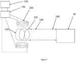
- FIG. 6 shows an alternative electric machine suitable 131 for use with the gas turbine engine 10.
- the electric machine 131 is a synchronous electric machine comprising a stator 132 having stator magnets 133.
- the stator magnets are in the form of electromagnets, formed by electrically excited windings 133.
- the windings 133 are provided with AC current, which interacts with AC or DC current fed to windings 135 of a rotor 134, which is similar to the rotor 34.
- the rotor windings 135 are electrically coupled to the capacitor 30.
- an inverter (not shown) will be required between the capacitor 30 and windings 131.
- the inverter can be omitted, with the windings 131 being provided with DC current, thereby reducing the amount of power electronics required.
- the magnetic fields interact to produce a torque to rotate the motor 131, which is again coupled to the compressor 14.
- the electric machine 131 can act as a generator, with a fluctuating magnetic field generated by the stator windings 133 generating an electric current in the rotor windings. Consequently, the electric machine 131 can similarly act as either a motor or a generator, to boost the compressor 14, or to charge the capacitor 30 from electricity generated by the electric machine 131.
- stator windings 133 are coupled to an additional power source, such as a separate generator or battery 141. Where a DC power source such as a battery 141 is provided, power electronics 136 in the form of an inverter is required, to convert the DC current to AC current.
- the stator windings 133 are also optionally coupled to one or more electrical loads, such as fuel pumps, flight surface actuators etc. Consequently, the electric machine 131 can be used to power more than just the capacitor 30 and electric machine 131 when acting as a motor, and can be used as a generator for general purposes.
- greater control can be provided over the electric machine 131 relative to the permanent magnet machine 31, as the electric machine 131 contains no permanent magnets, and so can be turned off when desired.
- the capacitors 30 only have to generate a fraction of the electrical current required by the electric machine, and so their storage capacity can be smaller for a given amount of generator power. Consequently, the relative small storage capacity of the capacitors 30 can nevertheless provide for a relatively large duration of operation of the motor 31.
- power electronics i.e. an inverter
- a rectifier will still generally be required in series between the rotor windings 135 and capacitors 30, to convert AC current generated by the rotor windings 135 to DC current when the electric machine 131 is operated as a generator.
- Such machines can be turned off, by cutting off electrical current to the rotor.
- a method for providing current to the rotor coils Conventionally, this would include either a separate generator provided on the same shaft as the main generator, a rotating transformer, or brushes.
- an electric storage device is provided, which rotates with the rotor, and which is charged by the electric machine acting as a generator. Consequently, these separate generators, transformers and bushes can be omitted, greatly reducing the weight of the system.
- the permanent magnets can be provided radially outward of the wound rotor, where cooling air is available. Consequently, the permanent magnets can operate in a cooler environment, thereby preventing demagnetisation.
- the electric machine 131 could also be operated as a rotating transformer, providing high current and / or high voltage supplied by the capacitor 30 to the stator windings 133, by, for instance, supplying high current DC electricity to the rotor windings 135, which is then transferred to the stator windings 133 electromagnetically.
- the current and voltage within the stator windings 133 would then be dependent on the relative number of turns in the rotor windings 135 and stator windings 133, and the current and input voltage on the rotor windings 133.
- Figure 8 shows a second gas turbine engine 210.
- the second gas turbine engine 210 is similar to the gas turbine engine 10 of figures 1 to 6 , but has a different arrangement of shafts, compressors and turbines.
- the gas turbine engine 210 comprises in axial flow series, an air intake 212, a propulsive fan 213, a low pressure compressor 214a, a high pressure compressor 214b, combustion equipment 215, a high-pressure turbine 216, a low-pressure turbine 217 and an exhaust nozzle 218.
- a nacelle 220 generally surrounds the engine 10 and defines the intake 212.
- the gas turbine engine 210 works in a similar manner to the engine 210, so that air entering the intake 212 is accelerated by the fan 213 to produce two air flows: a first air flow into the compressors 214a, 214b and a second air flow which passes through a bypass duct 221 to provide propulsive thrust.
- the compressors 214a, 214b compress the air flow in series before delivering that air to the combustion equipment 215.
- the air flow is mixed with fuel and the mixture combusted.
- the resultant hot combustion products then expand through, and thereby drive the high and low-pressure turbines 216, 217 before being exhausted through the nozzle 18 to provide additional propulsive thrust.
- the high 216 pressure turbine drives the high pressure compressor 214b by a high pressure shaft 228.
- the low pressure turbine 217 drives both the low pressure compressor 214a and the fan 213, by a fan shaft 227.
- the gas turbine engine 210 further comprises an electric storage device 230, which is similar to the electric storage device 30 of the gas turbine engine 10, and again may comprise any of a capacitor, chemical battery and fuel cell.
- the capacitor is mounted to a compressor drum of the compressor 214a, in a similar manner to the capacitor 30 of the gas turbine engine 10.
- the storage device is 230 electrically coupled to an electric machine 231, which is similar to either the electric machine 31 or the electric machine 131.
- the electric machine 231 is coupled to both the low pressure compressor 214a and the fan 213. Consequently, the electric machine 231 can be used to boost engine thrust in use, by increasing fan 213 rotational speed, and can also be used to recover kinetic energy from the aircraft, by operating as a generator, with the electric machine being driven by the fan 213 acting as a windmill. Consequently, in this embodiment, even steeper descents can be made, and further increased thrust can be provided. Furthermore, additional thrust can be generated, whilst only driving part of the engine core, thereby allowing thrust increase, with a reduced energy requirement compared to the gas turbine engine 10.
- gas turbine engines to which the present disclosure may be applied may have alternative configurations.
- such engines may have an alternative number of interconnecting shafts (e.g. three) and/or an alternative number of compressors and/or turbines.
- the engine may comprise a gearbox provided in the drive train from a turbine to a compressor and/or fan.
- the gas turbine engine may comprise first and second compressors and a fan, each mounted on a separate shaft. Except where mutually exclusive, any of the features may be employed separately or in combination with any other features and the disclosure extends to and includes all combinations and sub-combinations of one or more features described herein.
Landscapes
- Engineering & Computer Science (AREA)
- Chemical & Material Sciences (AREA)
- Combustion & Propulsion (AREA)
- Mechanical Engineering (AREA)
- General Engineering & Computer Science (AREA)
- Connection Of Motors, Electrical Generators, Mechanical Devices, And The Like (AREA)
- Structures Of Non-Positive Displacement Pumps (AREA)
- Supercharger (AREA)
Applications Claiming Priority (1)
| Application Number | Priority Date | Filing Date | Title |
|---|---|---|---|
| GB201816024 | 2018-10-01 |
Publications (3)
| Publication Number | Publication Date |
|---|---|
| EP3633160A2 true EP3633160A2 (fr) | 2020-04-08 |
| EP3633160A3 EP3633160A3 (fr) | 2020-05-06 |
| EP3633160B1 EP3633160B1 (fr) | 2022-11-02 |
Family
ID=67928615
Family Applications (1)
| Application Number | Title | Priority Date | Filing Date |
|---|---|---|---|
| EP19196505.2A Active EP3633160B1 (fr) | 2018-10-01 | 2019-09-10 | Moteur de turbine à gaz avec accumulateur d'énergie intégré |
Country Status (2)
| Country | Link |
|---|---|
| US (1) | US11073109B2 (fr) |
| EP (1) | EP3633160B1 (fr) |
Cited By (5)
| Publication number | Priority date | Publication date | Assignee | Title |
|---|---|---|---|---|
| EP3779150A1 (fr) * | 2019-08-12 | 2021-02-17 | Raytheon Technologies Corporation | Amélioration de la fatigue de matériaux pour des systèmes de propulsion hybrides |
| GB2610658A (en) * | 2021-09-08 | 2023-03-15 | Rolls Royce Plc | An improved gas turbine engine |
| WO2024009020A1 (fr) * | 2022-07-05 | 2024-01-11 | Safran Electrical & Power | Turbomachine hybride autonome |
| US11879413B2 (en) | 2021-09-08 | 2024-01-23 | Rolls-Royce Plc | Gas turbine engine |
| US11976611B2 (en) | 2021-09-08 | 2024-05-07 | Rolls-Royce Plc | Gas turbine engine |
Families Citing this family (9)
| Publication number | Priority date | Publication date | Assignee | Title |
|---|---|---|---|---|
| FR3108945B1 (fr) * | 2020-04-03 | 2022-11-11 | Safran Aircraft Engines | Module de turbomachine equipe d’une machine electrique |
| GB2610570A (en) * | 2021-09-08 | 2023-03-15 | Rolls Royce Plc | An improved gas turbine engine |
| GB2610572A (en) | 2021-09-08 | 2023-03-15 | Rolls Royce Plc | An improved gas turbine engine |
| GB2610565A (en) | 2021-09-08 | 2023-03-15 | Rolls Royce Plc | An improved gas turbine engine |
| GB2610568A (en) | 2021-09-08 | 2023-03-15 | Rolls Royce Plc | An improved gas turbine engine |
| GB2610567A (en) | 2021-09-08 | 2023-03-15 | Rolls Royce Plc | An improved gas turbine engine |
| US11867131B2 (en) * | 2021-10-29 | 2024-01-09 | Rtx Corporation | Hybrid electric single engine descent mode activation logic |
| FR3152531A1 (fr) * | 2023-08-29 | 2025-03-07 | Safran Aircraft Engines | Turbomachine comprenant une machine électrique à aimants permanents pour alimenter une charge tournante |
| US12510029B1 (en) * | 2024-12-19 | 2025-12-30 | Rolls-Royce North American Technologies, Inc. | Electric generator in turbine engine |
Family Cites Families (8)
| Publication number | Priority date | Publication date | Assignee | Title |
|---|---|---|---|---|
| WO2006060014A1 (fr) * | 2004-12-01 | 2006-06-08 | United Technologies Corporation | Systeme de generateur-demarreur pour moteur de turbine a pression d’entree |
| US7621117B2 (en) * | 2006-06-19 | 2009-11-24 | Pratt & Whitney Canada Corp. | Apparatus and method for controlling engine windmilling |
| DE102008062088B4 (de) | 2008-12-12 | 2015-03-05 | Norbert Bayer | Vorrichtung zur Energie-Rückgewinnung in Flugzeugtriebwerken beim Landeanflug. |
| US20130052021A1 (en) * | 2011-08-23 | 2013-02-28 | United Technologies Corporation | Rotor asymmetry |
| US9325388B2 (en) * | 2012-06-21 | 2016-04-26 | Siemens Energy, Inc. | Wireless telemetry system including an induction power system |
| US9982606B2 (en) | 2014-10-01 | 2018-05-29 | Goodrich Corporation | Electric architecture with power storage cells |
| GB2539299B (en) * | 2015-06-12 | 2017-11-08 | Rolls Royce Corp | Battery arrangements for gas turbine engines |
| US11371430B2 (en) * | 2016-07-01 | 2022-06-28 | Raytheon Technologies Corporation | Power system for aircraft parallel hybrid gas turbine electric propulsion system |
-
2019
- 2019-09-10 EP EP19196505.2A patent/EP3633160B1/fr active Active
- 2019-09-13 US US16/569,987 patent/US11073109B2/en active Active
Cited By (9)
| Publication number | Priority date | Publication date | Assignee | Title |
|---|---|---|---|---|
| EP3779150A1 (fr) * | 2019-08-12 | 2021-02-17 | Raytheon Technologies Corporation | Amélioration de la fatigue de matériaux pour des systèmes de propulsion hybrides |
| US11415065B2 (en) | 2019-08-12 | 2022-08-16 | Raytheon Technologies Corporation | Material fatigue improvement for hybrid propulsion systems |
| GB2610658A (en) * | 2021-09-08 | 2023-03-15 | Rolls Royce Plc | An improved gas turbine engine |
| US11879413B2 (en) | 2021-09-08 | 2024-01-23 | Rolls-Royce Plc | Gas turbine engine |
| US11976611B2 (en) | 2021-09-08 | 2024-05-07 | Rolls-Royce Plc | Gas turbine engine |
| GB2610658B (en) * | 2021-09-08 | 2025-05-07 | Rolls Royce Plc | An improved gas turbine engine |
| WO2024009020A1 (fr) * | 2022-07-05 | 2024-01-11 | Safran Electrical & Power | Turbomachine hybride autonome |
| FR3137711A1 (fr) * | 2022-07-05 | 2024-01-12 | Safran Electrical & Power | Turbomachine hybride autonome |
| US12584441B2 (en) | 2022-07-05 | 2026-03-24 | Safran Electrical & Power | Self-contained hybrid turbine engine |
Also Published As
| Publication number | Publication date |
|---|---|
| US11073109B2 (en) | 2021-07-27 |
| EP3633160A3 (fr) | 2020-05-06 |
| EP3633160B1 (fr) | 2022-11-02 |
| US20200102914A1 (en) | 2020-04-02 |
Similar Documents
| Publication | Publication Date | Title |
|---|---|---|
| EP3633160B1 (fr) | Moteur de turbine à gaz avec accumulateur d'énergie intégré | |
| US11496010B2 (en) | Electric machines | |
| US8624415B2 (en) | Multi-rotor generator | |
| CA3086465C (fr) | Systeme d`alimentation electrique d`eolienne et transmission de couple amelioree | |
| US11594938B2 (en) | Electric machine with helical rotor conduit and axial fluid channel in stator slots | |
| EP2995555A1 (fr) | Système de propulsion | |
| US20140045648A1 (en) | Induction motor-permanent magnet generator tandem configuration starter-generator for hybrid vehicles | |
| US11611256B2 (en) | Electric drive systems | |
| US11811283B2 (en) | Electric machines | |
| US20230182920A1 (en) | Aircraft power and propulsion system | |
| GB2613788A (en) | Starting gas turbine engines | |
| CN120664118B (zh) | 一种高紧凑动力驱动装置、系统及动力设备 | |
| CN115714517A (zh) | 一种磁悬浮电机发电机 | |
| EP3416279B1 (fr) | Machine électrique | |
| Chalmers et al. | An axial-flux permanent-magnet generator for a gearless wind energy system | |
| EP4023477B1 (fr) | Groupe électrique hybride à moteur creux | |
| Bumby et al. | Axial flux, permanent magnet, generators for engine integration | |
| Zharkov et al. | Analysis of current state of the starting device for aircraft gas turbine engines | |
| EP4096069A1 (fr) | Turbo-alternateur d'aéronef | |
| Caricchi et al. | Prototype of Variable-Speed, Direct-Drive generator for wind power exploitation in extremely cold climates | |
| CN112160830B (zh) | 一种电动可调涡轮增压器及其控制方法 | |
| GB2574827A (en) | Generating electric power | |
| CN118188173A (zh) | 燃气涡轮发动机原位集成轮缘驱动型顺路航空发电机 | |
| CN111835180A (zh) | 电动车装置 |
Legal Events
| Date | Code | Title | Description |
|---|---|---|---|
| PUAI | Public reference made under article 153(3) epc to a published international application that has entered the european phase |
Free format text: ORIGINAL CODE: 0009012 |
|
| STAA | Information on the status of an ep patent application or granted ep patent |
Free format text: STATUS: THE APPLICATION HAS BEEN PUBLISHED |
|
| PUAL | Search report despatched |
Free format text: ORIGINAL CODE: 0009013 |
|
| AK | Designated contracting states |
Kind code of ref document: A2 Designated state(s): AL AT BE BG CH CY CZ DE DK EE ES FI FR GB GR HR HU IE IS IT LI LT LU LV MC MK MT NL NO PL PT RO RS SE SI SK SM TR |
|
| AX | Request for extension of the european patent |
Extension state: BA ME |
|
| AK | Designated contracting states |
Kind code of ref document: A3 Designated state(s): AL AT BE BG CH CY CZ DE DK EE ES FI FR GB GR HR HU IE IS IT LI LT LU LV MC MK MT NL NO PL PT RO RS SE SI SK SM TR |
|
| AX | Request for extension of the european patent |
Extension state: BA ME |
|
| RIC1 | Information provided on ipc code assigned before grant |
Ipc: F02C 6/14 20060101AFI20200402BHEP Ipc: F01D 15/10 20060101ALI20200402BHEP Ipc: F02C 6/10 20060101ALI20200402BHEP |
|
| STAA | Information on the status of an ep patent application or granted ep patent |
Free format text: STATUS: REQUEST FOR EXAMINATION WAS MADE |
|
| 17P | Request for examination filed |
Effective date: 20200610 |
|
| RBV | Designated contracting states (corrected) |
Designated state(s): AL AT BE BG CH CY CZ DE DK EE ES FI FR GB GR HR HU IE IS IT LI LT LU LV MC MK MT NL NO PL PT RO RS SE SI SK SM TR |
|
| GRAP | Despatch of communication of intention to grant a patent |
Free format text: ORIGINAL CODE: EPIDOSNIGR1 |
|
| STAA | Information on the status of an ep patent application or granted ep patent |
Free format text: STATUS: GRANT OF PATENT IS INTENDED |
|
| GRAS | Grant fee paid |
Free format text: ORIGINAL CODE: EPIDOSNIGR3 |
|
| INTG | Intention to grant announced |
Effective date: 20220726 |
|
| GRAA | (expected) grant |
Free format text: ORIGINAL CODE: 0009210 |
|
| STAA | Information on the status of an ep patent application or granted ep patent |
Free format text: STATUS: THE PATENT HAS BEEN GRANTED |
|
| AK | Designated contracting states |
Kind code of ref document: B1 Designated state(s): AL AT BE BG CH CY CZ DE DK EE ES FI FR GB GR HR HU IE IS IT LI LT LU LV MC MK MT NL NO PL PT RO RS SE SI SK SM TR |
|
| REG | Reference to a national code |
Ref country code: GB Ref legal event code: FG4D |
|
| REG | Reference to a national code |
Ref country code: CH Ref legal event code: EP Ref country code: AT Ref legal event code: REF Ref document number: 1528913 Country of ref document: AT Kind code of ref document: T Effective date: 20221115 |
|
| REG | Reference to a national code |
Ref country code: DE Ref legal event code: R096 Ref document number: 602019021354 Country of ref document: DE |
|
| REG | Reference to a national code |
Ref country code: IE Ref legal event code: FG4D |
|
| REG | Reference to a national code |
Ref country code: LT Ref legal event code: MG9D |
|
| REG | Reference to a national code |
Ref country code: NL Ref legal event code: MP Effective date: 20221102 |
|
| REG | Reference to a national code |
Ref country code: AT Ref legal event code: MK05 Ref document number: 1528913 Country of ref document: AT Kind code of ref document: T Effective date: 20221102 |
|
| PG25 | Lapsed in a contracting state [announced via postgrant information from national office to epo] |
Ref country code: SE Free format text: LAPSE BECAUSE OF FAILURE TO SUBMIT A TRANSLATION OF THE DESCRIPTION OR TO PAY THE FEE WITHIN THE PRESCRIBED TIME-LIMIT Effective date: 20221102 Ref country code: PT Free format text: LAPSE BECAUSE OF FAILURE TO SUBMIT A TRANSLATION OF THE DESCRIPTION OR TO PAY THE FEE WITHIN THE PRESCRIBED TIME-LIMIT Effective date: 20230302 Ref country code: NO Free format text: LAPSE BECAUSE OF FAILURE TO SUBMIT A TRANSLATION OF THE DESCRIPTION OR TO PAY THE FEE WITHIN THE PRESCRIBED TIME-LIMIT Effective date: 20230202 Ref country code: LT Free format text: LAPSE BECAUSE OF FAILURE TO SUBMIT A TRANSLATION OF THE DESCRIPTION OR TO PAY THE FEE WITHIN THE PRESCRIBED TIME-LIMIT Effective date: 20221102 Ref country code: FI Free format text: LAPSE BECAUSE OF FAILURE TO SUBMIT A TRANSLATION OF THE DESCRIPTION OR TO PAY THE FEE WITHIN THE PRESCRIBED TIME-LIMIT Effective date: 20221102 Ref country code: ES Free format text: LAPSE BECAUSE OF FAILURE TO SUBMIT A TRANSLATION OF THE DESCRIPTION OR TO PAY THE FEE WITHIN THE PRESCRIBED TIME-LIMIT Effective date: 20221102 Ref country code: AT Free format text: LAPSE BECAUSE OF FAILURE TO SUBMIT A TRANSLATION OF THE DESCRIPTION OR TO PAY THE FEE WITHIN THE PRESCRIBED TIME-LIMIT Effective date: 20221102 |
|
| PG25 | Lapsed in a contracting state [announced via postgrant information from national office to epo] |
Ref country code: RS Free format text: LAPSE BECAUSE OF FAILURE TO SUBMIT A TRANSLATION OF THE DESCRIPTION OR TO PAY THE FEE WITHIN THE PRESCRIBED TIME-LIMIT Effective date: 20221102 Ref country code: PL Free format text: LAPSE BECAUSE OF FAILURE TO SUBMIT A TRANSLATION OF THE DESCRIPTION OR TO PAY THE FEE WITHIN THE PRESCRIBED TIME-LIMIT Effective date: 20221102 Ref country code: LV Free format text: LAPSE BECAUSE OF FAILURE TO SUBMIT A TRANSLATION OF THE DESCRIPTION OR TO PAY THE FEE WITHIN THE PRESCRIBED TIME-LIMIT Effective date: 20221102 Ref country code: IS Free format text: LAPSE BECAUSE OF FAILURE TO SUBMIT A TRANSLATION OF THE DESCRIPTION OR TO PAY THE FEE WITHIN THE PRESCRIBED TIME-LIMIT Effective date: 20230302 Ref country code: HR Free format text: LAPSE BECAUSE OF FAILURE TO SUBMIT A TRANSLATION OF THE DESCRIPTION OR TO PAY THE FEE WITHIN THE PRESCRIBED TIME-LIMIT Effective date: 20221102 Ref country code: GR Free format text: LAPSE BECAUSE OF FAILURE TO SUBMIT A TRANSLATION OF THE DESCRIPTION OR TO PAY THE FEE WITHIN THE PRESCRIBED TIME-LIMIT Effective date: 20230203 |
|
| PG25 | Lapsed in a contracting state [announced via postgrant information from national office to epo] |
Ref country code: NL Free format text: LAPSE BECAUSE OF FAILURE TO SUBMIT A TRANSLATION OF THE DESCRIPTION OR TO PAY THE FEE WITHIN THE PRESCRIBED TIME-LIMIT Effective date: 20221102 |
|
| P01 | Opt-out of the competence of the unified patent court (upc) registered |
Effective date: 20230528 |
|
| PG25 | Lapsed in a contracting state [announced via postgrant information from national office to epo] |
Ref country code: SM Free format text: LAPSE BECAUSE OF FAILURE TO SUBMIT A TRANSLATION OF THE DESCRIPTION OR TO PAY THE FEE WITHIN THE PRESCRIBED TIME-LIMIT Effective date: 20221102 Ref country code: RO Free format text: LAPSE BECAUSE OF FAILURE TO SUBMIT A TRANSLATION OF THE DESCRIPTION OR TO PAY THE FEE WITHIN THE PRESCRIBED TIME-LIMIT Effective date: 20221102 Ref country code: EE Free format text: LAPSE BECAUSE OF FAILURE TO SUBMIT A TRANSLATION OF THE DESCRIPTION OR TO PAY THE FEE WITHIN THE PRESCRIBED TIME-LIMIT Effective date: 20221102 Ref country code: DK Free format text: LAPSE BECAUSE OF FAILURE TO SUBMIT A TRANSLATION OF THE DESCRIPTION OR TO PAY THE FEE WITHIN THE PRESCRIBED TIME-LIMIT Effective date: 20221102 Ref country code: CZ Free format text: LAPSE BECAUSE OF FAILURE TO SUBMIT A TRANSLATION OF THE DESCRIPTION OR TO PAY THE FEE WITHIN THE PRESCRIBED TIME-LIMIT Effective date: 20221102 |
|
| REG | Reference to a national code |
Ref country code: DE Ref legal event code: R097 Ref document number: 602019021354 Country of ref document: DE |
|
| PG25 | Lapsed in a contracting state [announced via postgrant information from national office to epo] |
Ref country code: SK Free format text: LAPSE BECAUSE OF FAILURE TO SUBMIT A TRANSLATION OF THE DESCRIPTION OR TO PAY THE FEE WITHIN THE PRESCRIBED TIME-LIMIT Effective date: 20221102 Ref country code: AL Free format text: LAPSE BECAUSE OF FAILURE TO SUBMIT A TRANSLATION OF THE DESCRIPTION OR TO PAY THE FEE WITHIN THE PRESCRIBED TIME-LIMIT Effective date: 20221102 |
|
| PLBE | No opposition filed within time limit |
Free format text: ORIGINAL CODE: 0009261 |
|
| STAA | Information on the status of an ep patent application or granted ep patent |
Free format text: STATUS: NO OPPOSITION FILED WITHIN TIME LIMIT |
|
| 26N | No opposition filed |
Effective date: 20230803 |
|
| PG25 | Lapsed in a contracting state [announced via postgrant information from national office to epo] |
Ref country code: SI Free format text: LAPSE BECAUSE OF FAILURE TO SUBMIT A TRANSLATION OF THE DESCRIPTION OR TO PAY THE FEE WITHIN THE PRESCRIBED TIME-LIMIT Effective date: 20221102 |
|
| REG | Reference to a national code |
Ref country code: CH Ref legal event code: PL |
|
| PG25 | Lapsed in a contracting state [announced via postgrant information from national office to epo] |
Ref country code: LU Free format text: LAPSE BECAUSE OF NON-PAYMENT OF DUE FEES Effective date: 20230910 |
|
| REG | Reference to a national code |
Ref country code: BE Ref legal event code: MM Effective date: 20230930 |
|
| PG25 | Lapsed in a contracting state [announced via postgrant information from national office to epo] |
Ref country code: LU Free format text: LAPSE BECAUSE OF NON-PAYMENT OF DUE FEES Effective date: 20230910 Ref country code: IT Free format text: LAPSE BECAUSE OF FAILURE TO SUBMIT A TRANSLATION OF THE DESCRIPTION OR TO PAY THE FEE WITHIN THE PRESCRIBED TIME-LIMIT Effective date: 20221102 Ref country code: MC Free format text: LAPSE BECAUSE OF FAILURE TO SUBMIT A TRANSLATION OF THE DESCRIPTION OR TO PAY THE FEE WITHIN THE PRESCRIBED TIME-LIMIT Effective date: 20221102 |
|
| REG | Reference to a national code |
Ref country code: IE Ref legal event code: MM4A |
|
| PG25 | Lapsed in a contracting state [announced via postgrant information from national office to epo] |
Ref country code: IE Free format text: LAPSE BECAUSE OF NON-PAYMENT OF DUE FEES Effective date: 20230910 |
|
| PG25 | Lapsed in a contracting state [announced via postgrant information from national office to epo] |
Ref country code: CH Free format text: LAPSE BECAUSE OF NON-PAYMENT OF DUE FEES Effective date: 20230930 |
|
| PG25 | Lapsed in a contracting state [announced via postgrant information from national office to epo] |
Ref country code: IE Free format text: LAPSE BECAUSE OF NON-PAYMENT OF DUE FEES Effective date: 20230910 Ref country code: CH Free format text: LAPSE BECAUSE OF NON-PAYMENT OF DUE FEES Effective date: 20230930 |
|
| PG25 | Lapsed in a contracting state [announced via postgrant information from national office to epo] |
Ref country code: BE Free format text: LAPSE BECAUSE OF NON-PAYMENT OF DUE FEES Effective date: 20230930 |
|
| PG25 | Lapsed in a contracting state [announced via postgrant information from national office to epo] |
Ref country code: BG Free format text: LAPSE BECAUSE OF FAILURE TO SUBMIT A TRANSLATION OF THE DESCRIPTION OR TO PAY THE FEE WITHIN THE PRESCRIBED TIME-LIMIT Effective date: 20221102 |
|
| PG25 | Lapsed in a contracting state [announced via postgrant information from national office to epo] |
Ref country code: BG Free format text: LAPSE BECAUSE OF FAILURE TO SUBMIT A TRANSLATION OF THE DESCRIPTION OR TO PAY THE FEE WITHIN THE PRESCRIBED TIME-LIMIT Effective date: 20221102 |
|
| PG25 | Lapsed in a contracting state [announced via postgrant information from national office to epo] |
Ref country code: CY Free format text: LAPSE BECAUSE OF FAILURE TO SUBMIT A TRANSLATION OF THE DESCRIPTION OR TO PAY THE FEE WITHIN THE PRESCRIBED TIME-LIMIT; INVALID AB INITIO Effective date: 20190910 |
|
| PG25 | Lapsed in a contracting state [announced via postgrant information from national office to epo] |
Ref country code: HU Free format text: LAPSE BECAUSE OF FAILURE TO SUBMIT A TRANSLATION OF THE DESCRIPTION OR TO PAY THE FEE WITHIN THE PRESCRIBED TIME-LIMIT; INVALID AB INITIO Effective date: 20190910 |
|
| PGFP | Annual fee paid to national office [announced via postgrant information from national office to epo] |
Ref country code: DE Payment date: 20250926 Year of fee payment: 7 |
|
| PGFP | Annual fee paid to national office [announced via postgrant information from national office to epo] |
Ref country code: GB Payment date: 20250923 Year of fee payment: 7 |
|
| PGFP | Annual fee paid to national office [announced via postgrant information from national office to epo] |
Ref country code: FR Payment date: 20250925 Year of fee payment: 7 |
|
| PG25 | Lapsed in a contracting state [announced via postgrant information from national office to epo] |
Ref country code: TR Free format text: LAPSE BECAUSE OF FAILURE TO SUBMIT A TRANSLATION OF THE DESCRIPTION OR TO PAY THE FEE WITHIN THE PRESCRIBED TIME-LIMIT Effective date: 20221102 |