EP3633162B1 - Wärmetauschersystem für strahltriebwerk - Google Patents
Wärmetauschersystem für strahltriebwerk Download PDFInfo
- Publication number
- EP3633162B1 EP3633162B1 EP19201553.5A EP19201553A EP3633162B1 EP 3633162 B1 EP3633162 B1 EP 3633162B1 EP 19201553 A EP19201553 A EP 19201553A EP 3633162 B1 EP3633162 B1 EP 3633162B1
- Authority
- EP
- European Patent Office
- Prior art keywords
- shaft
- gas turbine
- turbine engine
- axis
- heat exchanger
- Prior art date
- Legal status (The legal status is an assumption and is not a legal conclusion. Google has not performed a legal analysis and makes no representation as to the accuracy of the status listed.)
- Active
Links
Images


Classifications
-
- F—MECHANICAL ENGINEERING; LIGHTING; HEATING; WEAPONS; BLASTING
- F02—COMBUSTION ENGINES; HOT-GAS OR COMBUSTION-PRODUCT ENGINE PLANTS
- F02C—GAS-TURBINE PLANTS; AIR INTAKES FOR JET-PROPULSION PLANTS; CONTROLLING FUEL SUPPLY IN AIR-BREATHING JET-PROPULSION PLANTS
- F02C7/00—Features, components parts, details or accessories, not provided for in, or of interest apart form groups F02C1/00 - F02C6/00; Air intakes for jet-propulsion plants
- F02C7/12—Cooling of plants
- F02C7/16—Cooling of plants characterised by cooling medium
- F02C7/18—Cooling of plants characterised by cooling medium the medium being gaseous, e.g. air
-
- F—MECHANICAL ENGINEERING; LIGHTING; HEATING; WEAPONS; BLASTING
- F02—COMBUSTION ENGINES; HOT-GAS OR COMBUSTION-PRODUCT ENGINE PLANTS
- F02C—GAS-TURBINE PLANTS; AIR INTAKES FOR JET-PROPULSION PLANTS; CONTROLLING FUEL SUPPLY IN AIR-BREATHING JET-PROPULSION PLANTS
- F02C3/00—Gas-turbine plants characterised by the use of combustion products as the working fluid
- F02C3/14—Gas-turbine plants characterised by the use of combustion products as the working fluid characterised by the arrangement of the combustion chamber in the plant
-
- F—MECHANICAL ENGINEERING; LIGHTING; HEATING; WEAPONS; BLASTING
- F02—COMBUSTION ENGINES; HOT-GAS OR COMBUSTION-PRODUCT ENGINE PLANTS
- F02C—GAS-TURBINE PLANTS; AIR INTAKES FOR JET-PROPULSION PLANTS; CONTROLLING FUEL SUPPLY IN AIR-BREATHING JET-PROPULSION PLANTS
- F02C7/00—Features, components parts, details or accessories, not provided for in, or of interest apart form groups F02C1/00 - F02C6/00; Air intakes for jet-propulsion plants
- F02C7/04—Air intakes for gas-turbine plants or jet-propulsion plants
-
- F—MECHANICAL ENGINEERING; LIGHTING; HEATING; WEAPONS; BLASTING
- F02—COMBUSTION ENGINES; HOT-GAS OR COMBUSTION-PRODUCT ENGINE PLANTS
- F02C—GAS-TURBINE PLANTS; AIR INTAKES FOR JET-PROPULSION PLANTS; CONTROLLING FUEL SUPPLY IN AIR-BREATHING JET-PROPULSION PLANTS
- F02C7/00—Features, components parts, details or accessories, not provided for in, or of interest apart form groups F02C1/00 - F02C6/00; Air intakes for jet-propulsion plants
- F02C7/36—Power transmission arrangements between the different shafts of the gas turbine plant, or between the gas-turbine plant and the power user
-
- F—MECHANICAL ENGINEERING; LIGHTING; HEATING; WEAPONS; BLASTING
- F02—COMBUSTION ENGINES; HOT-GAS OR COMBUSTION-PRODUCT ENGINE PLANTS
- F02K—JET-PROPULSION PLANTS
- F02K3/00—Plants including a gas turbine driving a compressor or a ducted fan
- F02K3/02—Plants including a gas turbine driving a compressor or a ducted fan in which part of the working fluid by-passes the turbine and combustion chamber
- F02K3/04—Plants including a gas turbine driving a compressor or a ducted fan in which part of the working fluid by-passes the turbine and combustion chamber the plant including ducted fans, i.e. fans with high volume, low pressure outputs, for augmenting the jet thrust, e.g. of double-flow type
- F02K3/06—Plants including a gas turbine driving a compressor or a ducted fan in which part of the working fluid by-passes the turbine and combustion chamber the plant including ducted fans, i.e. fans with high volume, low pressure outputs, for augmenting the jet thrust, e.g. of double-flow type with front fan
-
- F—MECHANICAL ENGINEERING; LIGHTING; HEATING; WEAPONS; BLASTING
- F05—INDEXING SCHEMES RELATING TO ENGINES OR PUMPS IN VARIOUS SUBCLASSES OF CLASSES F01-F04
- F05D—INDEXING SCHEME FOR ASPECTS RELATING TO NON-POSITIVE-DISPLACEMENT MACHINES OR ENGINES, GAS-TURBINES OR JET-PROPULSION PLANTS
- F05D2250/00—Geometry
- F05D2250/30—Arrangement of components
- F05D2250/31—Arrangement of components according to the direction of their main axis or their axis of rotation
- F05D2250/312—Arrangement of components according to the direction of their main axis or their axis of rotation the axes being parallel to each other
-
- F—MECHANICAL ENGINEERING; LIGHTING; HEATING; WEAPONS; BLASTING
- F05—INDEXING SCHEMES RELATING TO ENGINES OR PUMPS IN VARIOUS SUBCLASSES OF CLASSES F01-F04
- F05D—INDEXING SCHEME FOR ASPECTS RELATING TO NON-POSITIVE-DISPLACEMENT MACHINES OR ENGINES, GAS-TURBINES OR JET-PROPULSION PLANTS
- F05D2250/00—Geometry
- F05D2250/30—Arrangement of components
- F05D2250/31—Arrangement of components according to the direction of their main axis or their axis of rotation
- F05D2250/314—Arrangement of components according to the direction of their main axis or their axis of rotation the axes being inclined in relation to each other
-
- F—MECHANICAL ENGINEERING; LIGHTING; HEATING; WEAPONS; BLASTING
- F05—INDEXING SCHEMES RELATING TO ENGINES OR PUMPS IN VARIOUS SUBCLASSES OF CLASSES F01-F04
- F05D—INDEXING SCHEME FOR ASPECTS RELATING TO NON-POSITIVE-DISPLACEMENT MACHINES OR ENGINES, GAS-TURBINES OR JET-PROPULSION PLANTS
- F05D2260/00—Function
- F05D2260/20—Heat transfer, e.g. cooling
- F05D2260/213—Heat transfer, e.g. cooling by the provision of a heat exchanger within the cooling circuit
-
- F—MECHANICAL ENGINEERING; LIGHTING; HEATING; WEAPONS; BLASTING
- F05—INDEXING SCHEMES RELATING TO ENGINES OR PUMPS IN VARIOUS SUBCLASSES OF CLASSES F01-F04
- F05D—INDEXING SCHEME FOR ASPECTS RELATING TO NON-POSITIVE-DISPLACEMENT MACHINES OR ENGINES, GAS-TURBINES OR JET-PROPULSION PLANTS
- F05D2260/00—Function
- F05D2260/20—Heat transfer, e.g. cooling
- F05D2260/232—Heat transfer, e.g. cooling characterized by the cooling medium
-
- F—MECHANICAL ENGINEERING; LIGHTING; HEATING; WEAPONS; BLASTING
- F05—INDEXING SCHEMES RELATING TO ENGINES OR PUMPS IN VARIOUS SUBCLASSES OF CLASSES F01-F04
- F05D—INDEXING SCHEME FOR ASPECTS RELATING TO NON-POSITIVE-DISPLACEMENT MACHINES OR ENGINES, GAS-TURBINES OR JET-PROPULSION PLANTS
- F05D2260/00—Function
- F05D2260/40—Transmission of power
- F05D2260/403—Transmission of power through the shape of the drive components
- F05D2260/4031—Transmission of power through the shape of the drive components as in toothed gearing
- F05D2260/40311—Transmission of power through the shape of the drive components as in toothed gearing of the epicyclical, planetary or differential type
-
- Y—GENERAL TAGGING OF NEW TECHNOLOGICAL DEVELOPMENTS; GENERAL TAGGING OF CROSS-SECTIONAL TECHNOLOGIES SPANNING OVER SEVERAL SECTIONS OF THE IPC; TECHNICAL SUBJECTS COVERED BY FORMER USPC CROSS-REFERENCE ART COLLECTIONS [XRACs] AND DIGESTS
- Y02—TECHNOLOGIES OR APPLICATIONS FOR MITIGATION OR ADAPTATION AGAINST CLIMATE CHANGE
- Y02T—CLIMATE CHANGE MITIGATION TECHNOLOGIES RELATED TO TRANSPORTATION
- Y02T50/00—Aeronautics or air transport
- Y02T50/60—Efficient propulsion technologies, e.g. for aircraft
Definitions
- This disclosure relates generally to gas turbine engines for vehicles, and more particularly to cooling systems associated with gas turbine engines.
- the present invention relates to an appartus as laid out in claim 1, whereby a gas turbine engine includes an offset core and a propulsion assembly.
- the offset core is configured to rotate about a first axis.
- the propulsion assembly includes a fan section and a low-pressure turbine connected to the offset core.
- the fan section is in communication with the low-pressure turbine by a shaft configured to rotate about a second axis, different than the first axis.
- the shaft includes a nosecone inlet duct, an inner channel, and at least one shaft vent.
- the nosecone inlet duct is disposed within the fan section.
- the inner channel extends along a length of the shaft between the nosecone inlet duct and at least one air duct circumscribing the shaft.
- the at least one shaft vent is disposed within the at least one air duct.
- the at least one air duct is configured to deliver air from the nosecone inlet duct to at least one heat exchanger.
- the propulsion assembly further includes a planetary gear system coupling the low-pressure turbine to the shaft.
- the inner channel extends substantially an entire length of the shaft.
- the shaft further includes a plurality of shaft seals configured to provide an air seal between the shaft and the at least one air duct.
- Each shaft seal of the plurality of shaft seals is disposed between the shaft and an inner surface of the at least one air duct in an annular array about a circumference of the shaft.
- the gas turbine engine further includes a core cowl arranged substantially about the second axis and enveloping at least a portion of the offset core and the propulsion assembly.
- the at least one air duct is configured to cool the core cowl by delivering air from the nosecone inlet duct to the core cowl.
- the offset core includes an accessory mount structure configured to hold the at least one heat exchanger.
- the core cowl and the accessory mount structure are configured to share at least a portion of a weight of the at least one heat exchanger.
- the first axis is angularly skewed with respect to the second axis.
- the first axis is substantially parallel to the second axis.
- the at least one heat exchanger is configured to extend in a radial direction substantially a distance between the propulsion assembly and the core cowl.
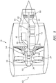
- FIG. 1 shows a gas turbine engine 10 including a propulsion assembly 22 and an offset core 12.
- the propulsion assembly 22 includes a fan section 24, having a fan 56, a shaft 30, and a low-pressure turbine 26, wherein the low-pressure turbine 26 rotates the shaft 30 which, in turn, rotates the fan 56.
- the offset core 12 is positioned to receive air from the fan 56 via a compressor transition duct 58 (e.g., an inlet duct).
- the offset core 12 includes a compressor section 14, a combustor section 16, and a turbine section 18. While the embodiments disclosed herein relate to aircraft gas turbine engines, the disclosure is not limited to aircraft gas turbine engines and may be used in gas turbine engines of any suitable vehicle.
- the compressor section 14 is driven by the turbine section 18.
- the combustor section 16 is positioned intermediate the compressor section 14 and the turbine section 18.
- a turbine transition duct 28 (e.g., an exhaust duct) extends downstream from the turbine section 18 into a low-pressure turbine 26 and further downstream into an exhaust section 60.
- the products of combustion, downstream of the turbine section 18, pass across the low-pressure turbine 26 which is driven to rotate the shaft 30, thereby rotating the fan 56.
- the low-pressure turbine 26 may drive the fan 56 through a speed reducing geared architecture, for example, a planetary gear system 42, which couples the low-pressure turbine 26 to the shaft 30 (see FIG. 2 ).
- the axis of the offset core 12 is offset with respect to the axis of the propulsion assembly 22.
- at least one of the compressor section 14 and the turbine section 18 may be configured to rotate about a first axis 20 while the shaft 30 of the propulsion assembly 22 is configured to rotate about a second axis 32, different than the first axis 20.
- the first axis 20 and the second axis 32 may be substantially parallel.
- the first axis 20 may be angularly skewed relative to the second axis 32.
- the gas turbine engine 10 further includes a core cowl 46 arranged substantially around the longitudinal axis of the propulsion assembly 22, for example, the second axis 32.
- the core cowl 46 is generally disposed within the gas turbine engine 10 between the fan section 24 and the aft end 64 of the gas turbine engine 10.
- the core cowl 46 may be positioned so as to envelope at least a portion of the offset core 12 and the propulsion assembly 22.
- the compressor transition duct 58 is disposed just aft of the fan 56 and is configured to convey air from the fan 56 to the offset core 12.
- the fan section 24 includes a plurality of fan exit guide vanes 54 positioned at the outlet of a fan case 52, for example, to direct air flow into the compressor section 14.
- the fan section 24 may further include a nosecone 50 disposed on the fan 56 at a forward end 62 of the gas turbine engine 10 and arranged substantially around the longitudinal axis of the propulsion assembly 22, for example, the second axis 32.
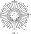
- FIGS. 2-4 illustrate the gas turbine engine 10 with an exemplary configuration of at least one heat exchanger 40.
- the at least one heat exchanger 40 is oriented, within the core cowl 46, between the propulsion assembly 22 and the core cowl 46.
- the at least one heat exchanger 40 may be oriented so as to extend in a radial direction (e.g., substantially the full radial distance) between the propulsion assembly 22 and the core cowl 46 (i.e., compared to a typical concentric shaft engine).
- the radial orientation of the at least one heat exchanger 40 thereby facilitates greater frontal surface area (i.e., intake area) of the at least one heat exchanger 40 with respect to total heat exchanger volume as compared to the same relationship found in heat exchanger applications on a typical concentric shaft engine.
- the at least one heat exchanger 40 may be any type, configuration, size, or shape of heat exchanger, for example, the at least one heat exchanger 40 may use forced air, liquid, etc. as a coolant or any other appropriate cooling medium.
- the at least one heat exchanger 40 may include heat exchangers having different types/configurations with respect to one another. Additionally, the at least one heat exchanger 40 may be used to provide cooling for electronics and/or other loads.
- the offset core 12 may further include an accessory mount structure 48 configured to hold the at least one heat exchanger 40.
- the at least one heat exchanger 40 as well as other external components, may be mounted on the accessory mount structure 48, for example, within the core cowl 46.
- the accessory mount structure 48 and the core cowl 46 may share the load (i.e., the weight) of the at least one heat exchanger 40 and other external components, thereby reducing the required size, and accordingly the weight, of the accessory mount structure 48.
- the accessory mount structure 48 may be mounted to the offset core 12 and extend outward from the offset core 12 into the core cowl 46 (e.g., an exoskeleton).
- the accessory mount structure 48 may include one or more mount points configured to support the load of larger heat exchangers.
- the shaft 30 includes a nosecone inlet duct 34 disposed within the fan section 24, an inner channel 66, and at least one shaft vent 36 disposed within at least one air duct 38.
- the inner channel 66 extends along a length of the shaft 30 between the nosecone inlet duct 34 and the at least one air duct 38.
- the at least one air duct 38 is configured to deliver air from the nosecone inlet duct 34 to the at least one heat exchanger 40 .
- the inner channel 66 may extend up to substantially the entire length of the shaft 30.
- FIG. 4 illustrates an exemplary air duct of the at least one air duct 38.
- the at least one air duct 38 circumscribes the shaft 30.
- the shaft 30 may include a plurality of shaft seals 44 configured to provide an air seal between the shaft 30 and the at least one air duct 38.
- each shaft seal of the plurality of shaft seals 44 may be disposed in an annular array about the outer circumference of the shaft 30 between the shaft 30 and an inner surface 68 of the at least one air duct 38.
- the at least one air duct 38 may be disposed about the shaft along a length of the shaft, for example, the at least one air duct 38 may include a forward air duct and an aft air duct configured to direct air to the at least one heat exchanger 40.
- the at least one air duct 38 may include air duct segments extending partially around the circumferences of the shaft 30 (e.g., about the second axis 32) in an annular arrangement extending about at least a portion of the shaft 30.
- the at least one shaft vent 36 may be disposed on the shaft 30 within the at least one air duct 38, for example, between the plurality of shaft seals 44 of the shaft 30 and a respective air duct of the at least one air duct 38.
- the at least one shaft vent 36 may be of any size, shape, or orientation (i.e., longitudinally or circumferentially) within the at least one air duct 38 so as to direct air from the inner channel 66 of the shaft 30 into the at least one air duct 38.
- the at least one shaft vent 36 may be configured to facilitate impeller action of the shaft 30 within the at least one air duct 38 (i.e., pumping of the air through the at least one air duct 38).
- the at least one shaft vent 36 may be configured to facilitate pumping of the air with minimal temperature increase (e.g., "aero-shaping" of the at least one shaft vent 36).
- air A1 transiting the shaft 30 via the inner channel 66 is directed into the at least one air duct 38 through the at least one shaft vent 36.
- the at least one air duct 38 direct air A2 into the at least one heat exchanger 40.
- each air duct of the at least one air duct 38 may direct air A2 into a single heat exchanger of the at least one heat exchanger 40.
- each air duct of the at least one air duct 38 may direct air A2 into more than one heat exchanger of the at least one heat exchanger 40.
- the at least one air duct 38 may be configured to cool the core cowl 46 by delivering air A3 from the nosecone inlet duct 34 to the core cowl 46
- the propulsion assembly 22 may include a planetary gear system 42 configured to impart a speed ratio between the fan 56 and the low-pressure turbine 26.
- the planetary gear system 42 may be disposed within the propulsion assembly or, alternatively outside the propulsion assembly 22, for example, within the turbine transition duct 28.
Landscapes
- Engineering & Computer Science (AREA)
- Chemical & Material Sciences (AREA)
- Combustion & Propulsion (AREA)
- Mechanical Engineering (AREA)
- General Engineering & Computer Science (AREA)
- Heat-Exchange Devices With Radiators And Conduit Assemblies (AREA)
Claims (12)
- Gasturbinentriebwerk (10), gekennzeichnet durch:einen versetzten Kern (12), der dazu konfiguriert ist, sich um eine erste Achse (20) zu drehen; undeine Antriebsbaugruppe (22), umfassend einen Fanabschnitt (24) und eine Niederdruckturbine (26), die mit dem versetzten Kern (12) verbunden sind, wobei der Fanabschnitt (24) in Kommunikation mit der Niederdruckturbine (26) durch eine Welle (30) steht, die dazu konfiguriert ist, sich um eine zweite Achse (32) zu drehen, die sich von der ersten Achse (20) unterscheidet, wobei die Welle (30) Folgendes umfasst:einen Bugkonuseinlasskanal (34), der innerhalb des Fanabschnitts (24) angeordnet ist;einen inneren Durchgang (66), der sich entlang einer Länge der Welle (30) zwischen dem Bugkonuseinlasskanal (34) und mindestens einem Luftkanal (38), der die Welle (30) umschreibt, erstreckt;mindestens eine Wellenentlüftung (36), die innerhalb des mindestens einen Luftkanals (38) angeordnet ist;und mindestens einen Wärmetauscher (40);wobei der mindestens eine Luftkanal (38) dazu konfiguriert ist, Luft aus dem Bugkonuseinlasskanal (34) an den mindestens einen Wärmetauscher (40) abzugeben.
- Gasturbinentriebwerk nach Anspruch 1, wobei die Antriebsbaugruppe (22) ferner ein Planetenradsystem (42) umfasst, das die Niederdruckturbine (26) an die Welle (30) koppelt.
- Gasturbinentriebwerk nach Anspruch 1 oder 2, wobei sich der innere Durchgang (66) im Wesentlichen eine gesamte Länge der Welle (30) erstreckt.
- Gasturbinentriebwerk nach Anspruch 1, 2 oder 3, wobei die Welle (30) ferner eine Vielzahl von Wellendichtungen (44) umfasst, die dazu konfiguriert ist, eine Luftdichtung zwischen der Welle (30) und dem mindestens einen Luftkanal (38) bereitzustellen, wobei jede Wellendichtung (44) der Vielzahl von Wellendichtungen (44) zwischen der Welle (30) und einer inneren Fläche (68) des mindestens einen Luftkanals (38) in einem ringförmigen Array um einen Umfang der Welle (30) angeordnet ist.
- Gasturbinentriebwerk nach einem der vorhergehenden Ansprüche, wobei der versetzte Kern (12) mindestens einen Verdichterabschnitt (14), einen Verbrennungsabschnitt (16) und einen Turbinenabschnitt (18) umfasst, wobei mindestens einer des Verdichterabschnitts (14) und des Turbinenabschnitts (18) dazu konfiguriert ist, sich um die erste Achse zu drehen.
- Gasturbinentriebwerk nach einem der vorhergehenden Ansprüche, ferner umfassend eine Kernverkleidung (36), die im Wesentlichen um die zweite Achse (32) angeordnet ist und mindestens einen Teil des versetzten Kerns (12) und der Antriebsbaugruppe (22) einhüllt.
- Gasturbinentriebwerk nach Anspruch 6, wobei der mindestens eine Luftkanal (38) dazu konfiguriert ist, die Kernverkleidung (36) zu kühlen, indem er Luft aus dem Bugkonuseinlasskanal (34) an die Kernverkleidung (36) abgibt.
- Gasturbinentriebwerk nach Anspruch 6 oder 7, wobei der versetzte Kern (12) ferner eine Nebenverbrauchermontagestruktur (48) umfasst, die dazu konfiguriert ist, den mindestens einen Wärmetauscher (40) zu halten.
- Gasturbinentriebwerk nach Anspruch 8, wobei die Kernverkleidung (36) und die Nebenverbrauchermontagestruktur (48) dazu konfiguriert sind, sich mindestens einen Teil eines Gewichts des mindestens einen Wärmetauschers (40) zu teilen.
- Gasturbinentriebwerk nach einem der Ansprüche 6 bis 9, wobei der mindestens eine Wärmetauscher (40) dazu konfiguriert ist, sich in einer radialen Richtung im Wesentlichen eine Strecke zwischen der Antriebsbaugruppe (22) und der Kernverkleidung (46) zu erstrecken.
- Gasturbinentriebwerk nach einem der vorhergehenden Ansprüche, wobei die erste Achse (20) winkelig schräg in Bezug auf die zweite Achse (32) ist.
- Gasturbinentriebwerk nach einem der Ansprüche 1 bis 10, wobei die erste Achse (20) im Wesentlichen parallel zu der zweiten Achse (32) ist.
Applications Claiming Priority (1)
| Application Number | Priority Date | Filing Date | Title |
|---|---|---|---|
| US16/151,864 US20200109667A1 (en) | 2018-10-04 | 2018-10-04 | Jet engine heat exchanger system |
Publications (2)
| Publication Number | Publication Date |
|---|---|
| EP3633162A1 EP3633162A1 (de) | 2020-04-08 |
| EP3633162B1 true EP3633162B1 (de) | 2021-12-01 |
Family
ID=68158981
Family Applications (1)
| Application Number | Title | Priority Date | Filing Date |
|---|---|---|---|
| EP19201553.5A Active EP3633162B1 (de) | 2018-10-04 | 2019-10-04 | Wärmetauschersystem für strahltriebwerk |
Country Status (2)
| Country | Link |
|---|---|
| US (1) | US20200109667A1 (de) |
| EP (1) | EP3633162B1 (de) |
Families Citing this family (3)
| Publication number | Priority date | Publication date | Assignee | Title |
|---|---|---|---|---|
| US12000334B1 (en) | 2023-03-08 | 2024-06-04 | Rtx Corporation | Heat exchanger(s) for recovering water and/or heat energy from turbine engine combustion products |
| US12577904B2 (en) * | 2023-04-28 | 2026-03-17 | Rtx Corporation | Offset core with side ejector nacelle nozzles |
| US20250059933A1 (en) * | 2023-08-14 | 2025-02-20 | The Boeing Company | Method of Nacelle Air Heat Exchanger Integration for a Hydrogen Fueled Fuel Cell Powered Aircraft |
Family Cites Families (5)
| Publication number | Priority date | Publication date | Assignee | Title |
|---|---|---|---|---|
| BE535079A (de) * | 1954-01-25 | |||
| US9115593B2 (en) * | 2012-04-02 | 2015-08-25 | United Technologies Corporation | Turbomachine thermal management |
| US10024235B2 (en) * | 2014-03-03 | 2018-07-17 | United Technologies Corporation | Offset core engine architecture |
| US10415466B2 (en) * | 2014-10-27 | 2019-09-17 | United Technologies Corporation | Offset cores for gas turbine engines |
| DE102017108597A1 (de) * | 2017-04-21 | 2018-10-25 | Rolls-Royce Deutschland Ltd & Co Kg | Strahltriebwerk mit einer Kühleinrichtung |
-
2018
- 2018-10-04 US US16/151,864 patent/US20200109667A1/en not_active Abandoned
-
2019
- 2019-10-04 EP EP19201553.5A patent/EP3633162B1/de active Active
Also Published As
| Publication number | Publication date |
|---|---|
| US20200109667A1 (en) | 2020-04-09 |
| EP3633162A1 (de) | 2020-04-08 |
Similar Documents
| Publication | Publication Date | Title |
|---|---|---|
| CN108368852B (zh) | 涡轮发动机或航空器的电动离心式压缩机 | |
| US8266888B2 (en) | Cooler in nacelle with radial coolant | |
| EP3054112B1 (de) | Nasenkonusbaugruppe und verfahren zum zirkulieren von luft in einem gasturbinentriebwerk | |
| EP3633162B1 (de) | Wärmetauschersystem für strahltriebwerk | |
| WO2014130103A2 (en) | Integrated heat exchangers for low fan pressure ratio geared turbofan | |
| US10773813B2 (en) | Aircraft with a propulsion unit comprising a fan at the rear of the fuselage | |
| EP4023872B1 (de) | Gasturbinentriebwerk | |
| US20260015976A1 (en) | Turbine engine including transfer gearbox and accessory gearbox | |
| US11821370B2 (en) | Cooling system for tail cone mounted generator | |
| CN112969843B (zh) | 设置有电机的飞行器涡轮发动机 | |
| US20230021361A1 (en) | Auxiliary power unit comprising a gas generator in direct-drive connection with an electric generator and an accessory gearbox | |
| EP4411116A1 (de) | Pufferluftsystem für einen lagerraum einer gasturbine | |
| US10941709B2 (en) | Gas turbine engine and cooling air configuration for turbine section thereof | |
| US12583609B2 (en) | Exhaust duct for hybrid aircraft powerplant | |
| US11873758B1 (en) | Gas turbine engine component with integral heat exchanger | |
| US12560133B2 (en) | Multiple-flow aircraft turbine engine | |
| EP3112634B1 (de) | Erweiterte verteilte motorarchitekturdesignalternative | |
| EP4239179A1 (de) | Fluggasturbinentriebwerk | |
| US20250290452A1 (en) | Turbine engine with accessory gearbox | |
| US12525841B2 (en) | Cooling an electric machine of a turbine engine powerplant | |
| US12522370B2 (en) | Rotorcraft powerplant cooling system | |
| US20250129747A1 (en) | Nacelle for a gas turbine engine | |
| CN121844126A (zh) | 航空涡轮发动机的环形壁和包括这种壁的航空涡轮发动机 | |
| US9790811B2 (en) | Gas generator with mount having air passages |
Legal Events
| Date | Code | Title | Description |
|---|---|---|---|
| PUAI | Public reference made under article 153(3) epc to a published international application that has entered the european phase |
Free format text: ORIGINAL CODE: 0009012 |
|
| STAA | Information on the status of an ep patent application or granted ep patent |
Free format text: STATUS: THE APPLICATION HAS BEEN PUBLISHED |
|
| AK | Designated contracting states |
Kind code of ref document: A1 Designated state(s): AL AT BE BG CH CY CZ DE DK EE ES FI FR GB GR HR HU IE IS IT LI LT LU LV MC MK MT NL NO PL PT RO RS SE SI SK SM TR |
|
| AX | Request for extension of the european patent |
Extension state: BA ME |
|
| STAA | Information on the status of an ep patent application or granted ep patent |
Free format text: STATUS: REQUEST FOR EXAMINATION WAS MADE |
|
| 17P | Request for examination filed |
Effective date: 20201008 |
|
| RBV | Designated contracting states (corrected) |
Designated state(s): AL AT BE BG CH CY CZ DE DK EE ES FI FR GB GR HR HU IE IS IT LI LT LU LV MC MK MT NL NO PL PT RO RS SE SI SK SM TR |
|
| RAP1 | Party data changed (applicant data changed or rights of an application transferred) |
Owner name: RAYTHEON TECHNOLOGIES CORPORATION |
|
| GRAP | Despatch of communication of intention to grant a patent |
Free format text: ORIGINAL CODE: EPIDOSNIGR1 |
|
| STAA | Information on the status of an ep patent application or granted ep patent |
Free format text: STATUS: GRANT OF PATENT IS INTENDED |
|
| INTG | Intention to grant announced |
Effective date: 20210517 |
|
| GRAS | Grant fee paid |
Free format text: ORIGINAL CODE: EPIDOSNIGR3 |
|
| GRAA | (expected) grant |
Free format text: ORIGINAL CODE: 0009210 |
|
| STAA | Information on the status of an ep patent application or granted ep patent |
Free format text: STATUS: THE PATENT HAS BEEN GRANTED |
|
| AK | Designated contracting states |
Kind code of ref document: B1 Designated state(s): AL AT BE BG CH CY CZ DE DK EE ES FI FR GB GR HR HU IE IS IT LI LT LU LV MC MK MT NL NO PL PT RO RS SE SI SK SM TR |
|
| REG | Reference to a national code |
Ref country code: GB Ref legal event code: FG4D |
|
| REG | Reference to a national code |
Ref country code: AT Ref legal event code: REF Ref document number: 1451970 Country of ref document: AT Kind code of ref document: T Effective date: 20211215 Ref country code: CH Ref legal event code: EP |
|
| REG | Reference to a national code |
Ref country code: IE Ref legal event code: FG4D |
|
| REG | Reference to a national code |
Ref country code: DE Ref legal event code: R096 Ref document number: 602019009686 Country of ref document: DE |
|
| REG | Reference to a national code |
Ref country code: LT Ref legal event code: MG9D |
|
| REG | Reference to a national code |
Ref country code: NL Ref legal event code: MP Effective date: 20211201 |
|
| REG | Reference to a national code |
Ref country code: AT Ref legal event code: MK05 Ref document number: 1451970 Country of ref document: AT Kind code of ref document: T Effective date: 20211201 |
|
| PG25 | Lapsed in a contracting state [announced via postgrant information from national office to epo] |
Ref country code: RS Free format text: LAPSE BECAUSE OF FAILURE TO SUBMIT A TRANSLATION OF THE DESCRIPTION OR TO PAY THE FEE WITHIN THE PRESCRIBED TIME-LIMIT Effective date: 20211201 Ref country code: LT Free format text: LAPSE BECAUSE OF FAILURE TO SUBMIT A TRANSLATION OF THE DESCRIPTION OR TO PAY THE FEE WITHIN THE PRESCRIBED TIME-LIMIT Effective date: 20211201 Ref country code: FI Free format text: LAPSE BECAUSE OF FAILURE TO SUBMIT A TRANSLATION OF THE DESCRIPTION OR TO PAY THE FEE WITHIN THE PRESCRIBED TIME-LIMIT Effective date: 20211201 Ref country code: BG Free format text: LAPSE BECAUSE OF FAILURE TO SUBMIT A TRANSLATION OF THE DESCRIPTION OR TO PAY THE FEE WITHIN THE PRESCRIBED TIME-LIMIT Effective date: 20220301 Ref country code: AT Free format text: LAPSE BECAUSE OF FAILURE TO SUBMIT A TRANSLATION OF THE DESCRIPTION OR TO PAY THE FEE WITHIN THE PRESCRIBED TIME-LIMIT Effective date: 20211201 |
|
| PG25 | Lapsed in a contracting state [announced via postgrant information from national office to epo] |
Ref country code: SE Free format text: LAPSE BECAUSE OF FAILURE TO SUBMIT A TRANSLATION OF THE DESCRIPTION OR TO PAY THE FEE WITHIN THE PRESCRIBED TIME-LIMIT Effective date: 20211201 Ref country code: PL Free format text: LAPSE BECAUSE OF FAILURE TO SUBMIT A TRANSLATION OF THE DESCRIPTION OR TO PAY THE FEE WITHIN THE PRESCRIBED TIME-LIMIT Effective date: 20211201 Ref country code: NO Free format text: LAPSE BECAUSE OF FAILURE TO SUBMIT A TRANSLATION OF THE DESCRIPTION OR TO PAY THE FEE WITHIN THE PRESCRIBED TIME-LIMIT Effective date: 20220301 Ref country code: LV Free format text: LAPSE BECAUSE OF FAILURE TO SUBMIT A TRANSLATION OF THE DESCRIPTION OR TO PAY THE FEE WITHIN THE PRESCRIBED TIME-LIMIT Effective date: 20211201 Ref country code: HR Free format text: LAPSE BECAUSE OF FAILURE TO SUBMIT A TRANSLATION OF THE DESCRIPTION OR TO PAY THE FEE WITHIN THE PRESCRIBED TIME-LIMIT Effective date: 20211201 Ref country code: GR Free format text: LAPSE BECAUSE OF FAILURE TO SUBMIT A TRANSLATION OF THE DESCRIPTION OR TO PAY THE FEE WITHIN THE PRESCRIBED TIME-LIMIT Effective date: 20220302 Ref country code: ES Free format text: LAPSE BECAUSE OF FAILURE TO SUBMIT A TRANSLATION OF THE DESCRIPTION OR TO PAY THE FEE WITHIN THE PRESCRIBED TIME-LIMIT Effective date: 20211201 |
|
| PG25 | Lapsed in a contracting state [announced via postgrant information from national office to epo] |
Ref country code: NL Free format text: LAPSE BECAUSE OF FAILURE TO SUBMIT A TRANSLATION OF THE DESCRIPTION OR TO PAY THE FEE WITHIN THE PRESCRIBED TIME-LIMIT Effective date: 20211201 |
|
| PG25 | Lapsed in a contracting state [announced via postgrant information from national office to epo] |
Ref country code: SM Free format text: LAPSE BECAUSE OF FAILURE TO SUBMIT A TRANSLATION OF THE DESCRIPTION OR TO PAY THE FEE WITHIN THE PRESCRIBED TIME-LIMIT Effective date: 20211201 Ref country code: SK Free format text: LAPSE BECAUSE OF FAILURE TO SUBMIT A TRANSLATION OF THE DESCRIPTION OR TO PAY THE FEE WITHIN THE PRESCRIBED TIME-LIMIT Effective date: 20211201 Ref country code: RO Free format text: LAPSE BECAUSE OF FAILURE TO SUBMIT A TRANSLATION OF THE DESCRIPTION OR TO PAY THE FEE WITHIN THE PRESCRIBED TIME-LIMIT Effective date: 20211201 Ref country code: PT Free format text: LAPSE BECAUSE OF FAILURE TO SUBMIT A TRANSLATION OF THE DESCRIPTION OR TO PAY THE FEE WITHIN THE PRESCRIBED TIME-LIMIT Effective date: 20220401 Ref country code: EE Free format text: LAPSE BECAUSE OF FAILURE TO SUBMIT A TRANSLATION OF THE DESCRIPTION OR TO PAY THE FEE WITHIN THE PRESCRIBED TIME-LIMIT Effective date: 20211201 Ref country code: CZ Free format text: LAPSE BECAUSE OF FAILURE TO SUBMIT A TRANSLATION OF THE DESCRIPTION OR TO PAY THE FEE WITHIN THE PRESCRIBED TIME-LIMIT Effective date: 20211201 |
|
| REG | Reference to a national code |
Ref country code: DE Ref legal event code: R097 Ref document number: 602019009686 Country of ref document: DE |
|
| PG25 | Lapsed in a contracting state [announced via postgrant information from national office to epo] |
Ref country code: IS Free format text: LAPSE BECAUSE OF FAILURE TO SUBMIT A TRANSLATION OF THE DESCRIPTION OR TO PAY THE FEE WITHIN THE PRESCRIBED TIME-LIMIT Effective date: 20220401 |
|
| PLBE | No opposition filed within time limit |
Free format text: ORIGINAL CODE: 0009261 |
|
| STAA | Information on the status of an ep patent application or granted ep patent |
Free format text: STATUS: NO OPPOSITION FILED WITHIN TIME LIMIT |
|
| PG25 | Lapsed in a contracting state [announced via postgrant information from national office to epo] |
Ref country code: DK Free format text: LAPSE BECAUSE OF FAILURE TO SUBMIT A TRANSLATION OF THE DESCRIPTION OR TO PAY THE FEE WITHIN THE PRESCRIBED TIME-LIMIT Effective date: 20211201 Ref country code: AL Free format text: LAPSE BECAUSE OF FAILURE TO SUBMIT A TRANSLATION OF THE DESCRIPTION OR TO PAY THE FEE WITHIN THE PRESCRIBED TIME-LIMIT Effective date: 20211201 |
|
| 26N | No opposition filed |
Effective date: 20220902 |
|
| PG25 | Lapsed in a contracting state [announced via postgrant information from national office to epo] |
Ref country code: SI Free format text: LAPSE BECAUSE OF FAILURE TO SUBMIT A TRANSLATION OF THE DESCRIPTION OR TO PAY THE FEE WITHIN THE PRESCRIBED TIME-LIMIT Effective date: 20211201 |
|
| PG25 | Lapsed in a contracting state [announced via postgrant information from national office to epo] |
Ref country code: MC Free format text: LAPSE BECAUSE OF FAILURE TO SUBMIT A TRANSLATION OF THE DESCRIPTION OR TO PAY THE FEE WITHIN THE PRESCRIBED TIME-LIMIT Effective date: 20211201 Ref country code: IT Free format text: LAPSE BECAUSE OF FAILURE TO SUBMIT A TRANSLATION OF THE DESCRIPTION OR TO PAY THE FEE WITHIN THE PRESCRIBED TIME-LIMIT Effective date: 20211201 |
|
| REG | Reference to a national code |
Ref country code: CH Ref legal event code: PL |
|
| REG | Reference to a national code |
Ref country code: BE Ref legal event code: MM Effective date: 20221031 |
|
| P01 | Opt-out of the competence of the unified patent court (upc) registered |
Effective date: 20230521 |
|
| PG25 | Lapsed in a contracting state [announced via postgrant information from national office to epo] |
Ref country code: LU Free format text: LAPSE BECAUSE OF NON-PAYMENT OF DUE FEES Effective date: 20221004 |
|
| PG25 | Lapsed in a contracting state [announced via postgrant information from national office to epo] |
Ref country code: LI Free format text: LAPSE BECAUSE OF NON-PAYMENT OF DUE FEES Effective date: 20221031 Ref country code: CH Free format text: LAPSE BECAUSE OF NON-PAYMENT OF DUE FEES Effective date: 20221031 |
|
| PG25 | Lapsed in a contracting state [announced via postgrant information from national office to epo] |
Ref country code: BE Free format text: LAPSE BECAUSE OF NON-PAYMENT OF DUE FEES Effective date: 20221031 |
|
| PG25 | Lapsed in a contracting state [announced via postgrant information from national office to epo] |
Ref country code: IE Free format text: LAPSE BECAUSE OF NON-PAYMENT OF DUE FEES Effective date: 20221004 |
|
| PG25 | Lapsed in a contracting state [announced via postgrant information from national office to epo] |
Ref country code: HU Free format text: LAPSE BECAUSE OF FAILURE TO SUBMIT A TRANSLATION OF THE DESCRIPTION OR TO PAY THE FEE WITHIN THE PRESCRIBED TIME-LIMIT; INVALID AB INITIO Effective date: 20191004 |
|
| PG25 | Lapsed in a contracting state [announced via postgrant information from national office to epo] |
Ref country code: CY Free format text: LAPSE BECAUSE OF FAILURE TO SUBMIT A TRANSLATION OF THE DESCRIPTION OR TO PAY THE FEE WITHIN THE PRESCRIBED TIME-LIMIT Effective date: 20211201 |
|
| PG25 | Lapsed in a contracting state [announced via postgrant information from national office to epo] |
Ref country code: MK Free format text: LAPSE BECAUSE OF FAILURE TO SUBMIT A TRANSLATION OF THE DESCRIPTION OR TO PAY THE FEE WITHIN THE PRESCRIBED TIME-LIMIT Effective date: 20211201 |
|
| PG25 | Lapsed in a contracting state [announced via postgrant information from national office to epo] |
Ref country code: MT Free format text: LAPSE BECAUSE OF FAILURE TO SUBMIT A TRANSLATION OF THE DESCRIPTION OR TO PAY THE FEE WITHIN THE PRESCRIBED TIME-LIMIT Effective date: 20211201 |
|
| REG | Reference to a national code |
Ref country code: DE Ref legal event code: R081 Ref document number: 602019009686 Country of ref document: DE Owner name: RTX CORPORATION (N.D.GES.D. STAATES DELAWARE),, US Free format text: FORMER OWNER: RAYTHEON TECHNOLOGIES CORPORATION, FARMINGTON, CT, US |
|
| PGFP | Annual fee paid to national office [announced via postgrant information from national office to epo] |
Ref country code: GB Payment date: 20250923 Year of fee payment: 7 |
|
| PGFP | Annual fee paid to national office [announced via postgrant information from national office to epo] |
Ref country code: FR Payment date: 20250924 Year of fee payment: 7 |
|
| PG25 | Lapsed in a contracting state [announced via postgrant information from national office to epo] |
Ref country code: TR Free format text: LAPSE BECAUSE OF FAILURE TO SUBMIT A TRANSLATION OF THE DESCRIPTION OR TO PAY THE FEE WITHIN THE PRESCRIBED TIME-LIMIT Effective date: 20211201 |
|
| PGFP | Annual fee paid to national office [announced via postgrant information from national office to epo] |
Ref country code: DE Payment date: 20250923 Year of fee payment: 7 |