EP3633164B1 - Getriebebefestigungselement einer gasturbinen - Google Patents
Getriebebefestigungselement einer gasturbinen Download PDFInfo
- Publication number
- EP3633164B1 EP3633164B1 EP19200568.4A EP19200568A EP3633164B1 EP 3633164 B1 EP3633164 B1 EP 3633164B1 EP 19200568 A EP19200568 A EP 19200568A EP 3633164 B1 EP3633164 B1 EP 3633164B1
- Authority
- EP
- European Patent Office
- Prior art keywords
- piece
- gearbox
- main body
- engine
- body portion
- Prior art date
- Legal status (The legal status is an assumption and is not a legal conclusion. Google has not performed a legal analysis and makes no representation as to the accuracy of the status listed.)
- Active
Links
Images



Classifications
-
- F—MECHANICAL ENGINEERING; LIGHTING; HEATING; WEAPONS; BLASTING
- F16—ENGINEERING ELEMENTS AND UNITS; GENERAL MEASURES FOR PRODUCING AND MAINTAINING EFFECTIVE FUNCTIONING OF MACHINES OR INSTALLATIONS; THERMAL INSULATION IN GENERAL
- F16H—GEARING
- F16H57/00—General details of gearing
- F16H57/02—Gearboxes; Mounting gearing therein
- F16H57/025—Support of gearboxes, e.g. torque arms, or attachment to other devices
-
- F—MECHANICAL ENGINEERING; LIGHTING; HEATING; WEAPONS; BLASTING
- F01—MACHINES OR ENGINES IN GENERAL; ENGINE PLANTS IN GENERAL; STEAM ENGINES
- F01D—NON-POSITIVE DISPLACEMENT MACHINES OR ENGINES, e.g. STEAM TURBINES
- F01D21/00—Shutting-down of machines or engines, e.g. in emergency; Regulating, controlling, or safety means not otherwise provided for
- F01D21/04—Shutting-down of machines or engines, e.g. in emergency; Regulating, controlling, or safety means not otherwise provided for responsive to undesired position of rotor relative to stator or to breaking-off of a part of the rotor, e.g. indicating such position
- F01D21/045—Shutting-down of machines or engines, e.g. in emergency; Regulating, controlling, or safety means not otherwise provided for responsive to undesired position of rotor relative to stator or to breaking-off of a part of the rotor, e.g. indicating such position special arrangements in stators or in rotors dealing with breaking-off of part of rotor
-
- F—MECHANICAL ENGINEERING; LIGHTING; HEATING; WEAPONS; BLASTING
- F01—MACHINES OR ENGINES IN GENERAL; ENGINE PLANTS IN GENERAL; STEAM ENGINES
- F01D—NON-POSITIVE DISPLACEMENT MACHINES OR ENGINES, e.g. STEAM TURBINES
- F01D21/00—Shutting-down of machines or engines, e.g. in emergency; Regulating, controlling, or safety means not otherwise provided for
- F01D21/14—Shutting-down of machines or engines, e.g. in emergency; Regulating, controlling, or safety means not otherwise provided for responsive to other specific conditions
-
- F—MECHANICAL ENGINEERING; LIGHTING; HEATING; WEAPONS; BLASTING
- F02—COMBUSTION ENGINES; HOT-GAS OR COMBUSTION-PRODUCT ENGINE PLANTS
- F02C—GAS-TURBINE PLANTS; AIR INTAKES FOR JET-PROPULSION PLANTS; CONTROLLING FUEL SUPPLY IN AIR-BREATHING JET-PROPULSION PLANTS
- F02C7/00—Features, components parts, details or accessories, not provided for in, or of interest apart form groups F02C1/00 - F02C6/00; Air intakes for jet-propulsion plants
- F02C7/32—Arrangement, mounting, or driving, of auxiliaries
-
- F—MECHANICAL ENGINEERING; LIGHTING; HEATING; WEAPONS; BLASTING
- F05—INDEXING SCHEMES RELATING TO ENGINES OR PUMPS IN VARIOUS SUBCLASSES OF CLASSES F01-F04
- F05D—INDEXING SCHEME FOR ASPECTS RELATING TO NON-POSITIVE-DISPLACEMENT MACHINES OR ENGINES, GAS-TURBINES OR JET-PROPULSION PLANTS
- F05D2250/00—Geometry
- F05D2250/30—Arrangement of components
- F05D2250/31—Arrangement of components according to the direction of their main axis or their axis of rotation
- F05D2250/313—Arrangement of components according to the direction of their main axis or their axis of rotation the axes being perpendicular to each other
-
- F—MECHANICAL ENGINEERING; LIGHTING; HEATING; WEAPONS; BLASTING
- F05—INDEXING SCHEMES RELATING TO ENGINES OR PUMPS IN VARIOUS SUBCLASSES OF CLASSES F01-F04
- F05D—INDEXING SCHEME FOR ASPECTS RELATING TO NON-POSITIVE-DISPLACEMENT MACHINES OR ENGINES, GAS-TURBINES OR JET-PROPULSION PLANTS
- F05D2250/00—Geometry
- F05D2250/40—Movement of components
- F05D2250/41—Movement of components with one degree of freedom
-
- F—MECHANICAL ENGINEERING; LIGHTING; HEATING; WEAPONS; BLASTING
- F05—INDEXING SCHEMES RELATING TO ENGINES OR PUMPS IN VARIOUS SUBCLASSES OF CLASSES F01-F04
- F05D—INDEXING SCHEME FOR ASPECTS RELATING TO NON-POSITIVE-DISPLACEMENT MACHINES OR ENGINES, GAS-TURBINES OR JET-PROPULSION PLANTS
- F05D2260/00—Function
- F05D2260/30—Retaining components in desired mutual position
- F05D2260/31—Retaining bolts or nuts
- F05D2260/311—Retaining bolts or nuts of the frangible or shear type
-
- F—MECHANICAL ENGINEERING; LIGHTING; HEATING; WEAPONS; BLASTING
- F05—INDEXING SCHEMES RELATING TO ENGINES OR PUMPS IN VARIOUS SUBCLASSES OF CLASSES F01-F04
- F05D—INDEXING SCHEME FOR ASPECTS RELATING TO NON-POSITIVE-DISPLACEMENT MACHINES OR ENGINES, GAS-TURBINES OR JET-PROPULSION PLANTS
- F05D2260/00—Function
- F05D2260/30—Retaining components in desired mutual position
- F05D2260/37—Retaining components in desired mutual position by a press fit connection
-
- F—MECHANICAL ENGINEERING; LIGHTING; HEATING; WEAPONS; BLASTING
- F05—INDEXING SCHEMES RELATING TO ENGINES OR PUMPS IN VARIOUS SUBCLASSES OF CLASSES F01-F04
- F05D—INDEXING SCHEME FOR ASPECTS RELATING TO NON-POSITIVE-DISPLACEMENT MACHINES OR ENGINES, GAS-TURBINES OR JET-PROPULSION PLANTS
- F05D2260/00—Function
- F05D2260/94—Functionality given by mechanical stress related aspects such as low cycle fatigue [LCF] of high cycle fatigue [HCF]
- F05D2260/941—Functionality given by mechanical stress related aspects such as low cycle fatigue [LCF] of high cycle fatigue [HCF] particularly aimed at mechanical or thermal stress reduction
-
- F—MECHANICAL ENGINEERING; LIGHTING; HEATING; WEAPONS; BLASTING
- F05—INDEXING SCHEMES RELATING TO ENGINES OR PUMPS IN VARIOUS SUBCLASSES OF CLASSES F01-F04
- F05D—INDEXING SCHEME FOR ASPECTS RELATING TO NON-POSITIVE-DISPLACEMENT MACHINES OR ENGINES, GAS-TURBINES OR JET-PROPULSION PLANTS
- F05D2260/00—Function
- F05D2260/96—Preventing, counteracting or reducing vibration or noise
Definitions
- This application relates generally to a mounting link between an engine structure and an attached structure, such as an auxiliary gearbox.
- Gas turbine engines such as for an aircraft, are designed to withstand a variety of loads. Attachment links between the engine and an attached structure must also be designed to withstand these loads.
- Some example loads are vibrational loads from the operation of the engine. These vibrational loads are relatively easy to predict. Another example are sudden, large loads from certain events. For instance, hard landings and "blade-off" events, in which blades of the engine detach due to impacts or the like, can create large loads or shocks on the engine and/or attached structures. These loads can cause damage to or disconnect the engine, gearbox, and other peripheral attachments to the engine and/or gearbox from one another, if not designed to withstand them. These types of loads are difficult to predict and can be orders of magnitude larger than other, loads that an engine experiences, such as the vibrational loads discussed above.
- EP 3219 962 A1 describes a one-degree-of-constraint semi-fusible gearbox mounting link.
- a link for mounting a first component to a second component is provided according to claim 1.
- the primary fastener is a fuse pin
- the fuse pin is snugly receivable in a fuse pin opening in the main body portion of the second piece and a fuse pin opening in the first piece.
- a plug to retains the fuse pin in the fuse pin opening in the first piece.
- the primary fastener is configured to break under an experienced load greater than a breakpoint load
- the secondary fastener is configured to withstand the experienced load
- the secondary fastener includes a threaded portion
- the main body portion of the second piece includes a corresponding threaded portion configured to mate with the threaded portion of the secondary fastener.
- first and second stop pin opening in the main body portion of the second piece are in opposed sides of the main body portion of the second piece.
- the primary fastener is a fuse pin, and includes a fuse pin opening in the main body portion of the second piece configured to receive the fuse pin, the fuse pin opening is situated between the first and second stop pin openings of the main body portion of the second piece.
- a diameter of the first and second stop pin openings in the first piece is larger than a diameter of a pin portion of the first and second stop pin assemblies.
- the link is configured to constrain the first piece with respect to the second piece in a single degree of freedom.
- the secondary fastener is arranged orthogonal to the primary fastener.
- gas turbine engine assembly according to claim 8, wherein the assembly comprises at least one mounting link according to claim 1.
- At least one stop pin assembly includes a first stop pin assembly and a second stop pin assembly, the first and second stop pin assemblies arranged on opposite sides of the fuse pin.
- the fuse pin is configured to break under an experienced load greater than a breakpoint load
- at least one stop pin assembly is configured to withstand the experienced load and the breakpoint load is greater than normal loads of the engine.
- the gas turbine engine includes a driveshaft connection point on the gearbox.
- the driveshaft connection point is configured to receive a drive shaft for transmitting torque between the engine and the gearbox.
- the driveshaft connecting point includes a seal
- the seal constrains the gearbox with respect to the engine in two degrees of freedom.
- At least one mounting link constrains the gearbox with respect to the engine in one degree of freedom.
- a method of constraining a gearbox with respect to an engine is provided according to claim 12.
- the primary fastener is configured to break under an experienced load greater than a breakpoint load
- the secondary fastener is configured to withstand the experienced load
- the breakpoint load is greater than normal loads of the engine.
- a mounting link connects an engine to a gearbox.
- the mounting link generally includes an engine attachment piece and a gearbox attachment piece.
- the first and second portions are connected to one another via two fasteners, a breakable primary fastener and a durable secondary fastener.
- the breakable primary fastener secures the engine attachment portion rigidly in a single degree of freedom with respect to the gearbox attachment portion, but is configured to break under a breakpoint load.
- the durable secondary fastener loosely constrains the engine attachment piece in a single degree of freedom with respect to the gearbox attachment piece, and is capable of withstanding the breakpoint load.
- Figure 1 schematically shows a perspective view of a gearbox assembly 10 for a gas turbine engine.
- the gearbox assembly 10 includes a gearbox 12 and one or more mounting links 22.
- the gearbox assembly 10 includes four mounting links 22, however, in other examples, the gearbox assembly 10 includes more or less mounting links 22.
- the mounting links 22 secure the gearbox 12 to an engine 100.
- the engine 100 is shown only schematically, and can be, for example, and aircraft gas turbine engine with an engine case, or another engine component to which the gearbox 12 is secured.
- the gearbox 12 includes a driveshaft connection point 14, which is configured to receive a driveshaft (not shown) to transmit torque between the engine 100 and the gearbox 12.
- the gearbox 12 also includes a seal 20 surrounding the driveshaft connection point 14.
- the gearbox 12 includes one or more peripheral drive connections 16, 18.
- the peripheral drive connections are connection points for auxiliary drive shafts driven by the gearbox 12 and engine 100, such as for air circulation systems or electrical generators.
- the driveshaft connection point 14, seal 20, and mounting links 22 constrain the gearbox 12 with respect to the engine 100 in all six translational and rotational degrees of freedom.
- the seal 20 is a spigot-type annular seal that constrains the gearbox 12 in two of the degrees of freedom in the plane of the seal 20.
- the mounting links 22 constrain the gearbox 12 in the remaining four degrees of freedom.
- the mounting link 22 is a celvis link.
- a clevis link generally includes three pieces: a first piece into which a second piece is received, and a pin securing the first and second pieces to one another, as will become more apparent with the subsequent description.
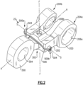
- the mounting link 22 includes an engine attachment piece 200 and a gearbox attachment piece 300.
- the engine attachment piece includes a main body portion 202 and first and second prongs 204a, 204b extending from the main body portion 202.
- Each of the first and second prongs 204a, 204b include an aperture 206a, 206b (respectively) which is configured to attach to the engine 100.
- a portion of the engine 100 may extend between the prongs 204a, 204b, and a pin (not shown) extends through the engine 100 and apertures 206a, 206b for attachment.
- the gearbox attachment piece 300 similarly includes a main body portion 302 and an aperture 304 which is configured to connect to the gearbox 12.
- a pin extends through aperture 304 and into or through gearbox 12 for attachment.
- the main body portion 302 of the gearbox attachment piece 300 is receivable in an opening 208 in the main body portion 202 of the engine attachment piece 200 in an interference fit relationship.
- the opening 208 is generally arranged along an axis A.
- the main body portion 302 is retained in connection with the main body portion 202 (and thus, the gearbox attachment piece 300 is retained in connected with the engine attachment piece 200) by a breakable primary fastener and a more durable secondary fastener, as will be discussed in more detail below.
- the breakable primary fastener secures the engine attachment piece 200 rigidly in a single degree of freedom with respect to the gearbox attachment piece 300, but is configured to break under a breakpoint load.
- the durable secondary fastener loosely constrains the engine attachment piece 200 in a single degree of freedom with respect to the gearbox attachment piece 300, and is capable of withstanding the breakpoint load.
- the breakable primary fastener is a fuse pin 400.
- the fuse pin 400 is snugly receivable in an opening 210 in the main body portion 202 of the engine attachment piece 200 and an opening 306 in the main body portion 302 of the gearbox attachment piece 300. In this way, the fuse pin 400 rigidly retains the main body portion 302 in the main body portion 202, which keeps the gearbox attachment piece 300 and the engine attachment piece 200 rigidly connected to one another.
- the openings 210 and 306 and fuse pin 400 are generally arranged along a common axis F, which is orthogonal to the axis A discussed above. In other words, the fuse pin 400 is arranged generally orthogonal with respect to the main body portion 302.
- a plug 402 is receivable in the opening 210 to keep the fuse pin 400 in place.
- the durable secondary fastener is a set of stop pin assemblies 500a, 500b.
- the stop pin assemblies 500a, 500b each include a pin portion 502 and an end cap portion 504, as best seen in Figure 4 .
- Pins 502 of the stop pin assemblies 500a, 500b extend through both the main body portion 202 of the engine attachment piece 200 and the main body portion 302 of the gearbox attachment piece 300.
- pins 502 are snugly receivable in a pair of openings 308a, 308b in opposed sides of the main body portion 302 on either side of opening 306 (which receives the fuse pin 400, as discussed above).
- pin assemblies 500a, 500b are bolts, and may include threading on pin portions 502 which corresponds to threading in the main body portions 302.
- pins 502 are loosely received in openings 212a, 212b in opposed sides of the main body portion 202. In other words, as can be seen in Figure 4 , the diameter of the openings 212a, 212b is larger than the diameter of the pins 502.
- openings 212a, 212b, 308a, and 308b and pins 502 are generally arranged along an axis S, which is orthogonal to the axes A and F. Accordingly, the pins 502 are arranged generally orthogonal with respect to the fuse pin 400.
- a locking wire 506 connects the end cap portions 504 of the stop pin assemblies 500a, 500b on an exterior of the mounting link 22 to further retain the stop pins assemblies 500a, 500b in place.
- the locking wire 506 prevents loosening of threads.
- thread loosening can be provided in other ways, such as by deformed male threads or helical inserts.
- the mounting link 22 may experience sudden large loads.
- a load is applied to the mounting link 22, it is transmitted between the engine attachment piece 200 and the gearbox attachment piece 300 via the fuse pin 400 (the breakable primary fastener).
- the fuse pin 400 is designed to break (or "fuse") under a breakaway load.
- the fuse pin 400 breaks when relative movement of engine attachment piece 200 and gearbox attachment piece 300 exerts a load on fuse pin 400 that is larger than the breakway load.
- the breakaway load is much higher (e.g., orders of magnitude), than normal operating loads experienced by the mounting link 22, (such as vibrational loads from engine 100) but is lower than sudden large loads experience by the mounting link 22, such as a "blade-out" event.
- the stop pin assemblies 500a, 500b prevent the engine attachment piece 200 and the gearbox attachment piece 300 from separating but allow some relative movement or mechanical play between the pieces 200, 300 as will be discussed in more detail below. This relative movement attenuates loads experienced by the pieces 200, 300 and the mounting link 22 itself. Additionally, the relative movement allows for Coulomb damping of forces transmitted between the engine attachment piece 200 and gearbox attachment piece 300.
- Coulomb damping is a type of damping in which energy is absorbed via sliding friction between adjacent pieces.
- main body portion 202 of the engine attachment piece and the main body portion 302 of the gearbox attachment piece are in an interference fit relationship with one another and thus generate sliding friction when moving relative to one another and provide Coulomb damping. Accordingly, once the fuse pin 400 is broken, the engine attachment piece 200 and the gearbox attachment piece 300 are still connected to one another, but forces transmitted between them are reduced by the Coulomb damping.
- the stop pin assemblies 500a, 500b are more durable relative to the fuse pin 400. In other words, the stop pin assemblies 500a, 500b can withstand forces greater than the breakaway force discussed above, including sudden large loads experience by the mounting link 22, such as a or "blade-out" event.
- the pins 502 are snugly received in openings 308a, 308b in the main body portion 302 of the gearbox attachment piece 300 but are only loosely received in openings 212a, 212b in the main body portion 202 of the engine attachment piece 200. Therefore, the main body portions 202 and 302 are somewhat able to move relative to one another as the pins 502 can move within the openings 212a, 212b. Since the pins 502 are snugly connected to the main body portion 302 of the gearbox attachment piece 300, the gearbox attachment piece 300 moves with the pins 502 as they move around in the openings 212a, 212b. Snug fits approach an interference fit, e.g., a "light" interference fit, or are an interference fit relationship.
- the mounting links 22 can have reduced cost, weight, size, and mechanical complexity as compared to a mounting link which is required to withstand very high loads in its entirety.
- the pieces 200 and 300 are described as engine attachment piece 200 and gearbox attachment piece 300. However, in other examples, the pieces 200 and 300 are switched such that the piece 200 is attached to the gearbox 12 while the piece 300 is attached to the engine 100.
Landscapes
- Engineering & Computer Science (AREA)
- General Engineering & Computer Science (AREA)
- Mechanical Engineering (AREA)
- Chemical & Material Sciences (AREA)
- Combustion & Propulsion (AREA)
- Snaps, Bayonet Connections, Set Pins, And Snap Rings (AREA)
Claims (13)
- Element (22) für eine Gasturbinenbaugruppe und zum Befestigen einer ersten Komponente an einer zweiten Komponente, Folgendes umfassend:ein erstes Teil, das mit der ersten Komponente verbindbar ist;ein zweites Teil, das mit der zweiten Komponente verbindbar ist, wobei das zweite Teil einen Hauptkörperabschnitt beinhaltet, der in einer Öffnung in dem ersten Teil aufnehmbar ist, wobei der Hauptkörperabschnitt des zweiten Teils in einer Presspassungsbeziehung mit der Öffnung in dem ersten Teil steht;einen primären Halter (400), der konfiguriert ist, um den Hauptkörperabschnitt des zweiten Teils in der Öffnung zurückzuhalten;einen sekundären Halter (500a, 500b), der konfiguriert ist, um den Hauptkörperabschnitt des zweiten Teils in der Öffnung zurückzuhalten, wobei der sekundäre Halter (500a, 500b) in der Lage ist, höheren Belastungen als der primäre Halter (400) standzuhalten, wobei der sekundäre Halter (500a, 500b) eine erste Anschlagstiftbaugruppe und eine zweite Anschlagstiftbaugruppe beinhaltet und die erste und die zweite Anschlagstiftbaugruppe in der ersten und der zweiten Anschlagstift-Öffnung in dem Hauptkörperabschnitt des zweiten Teils passgenau aufnehmbar sind und in der ersten und der zweiten Anschlagstift-Öffnung in dem ersten Teil lose aufnehmbar sind;
unddadurch gekennzeichnet, dass der sekundäre Halter (500a, 500b) orthogonal zu dem primären Halter (400) angeordnet ist. - Element nach Anspruch 1, wobei der primäre Halter (400) ein Sicherungsstift ist und der Sicherungsstift (400) in einer Sicherungsstiftöffnung in dem Hauptkörperabschnitt des zweiten Teils und einer Sicherungsstiftöffnung in dem ersten Teil passgenau aufnehmbar ist, und ferner einen Stopfen umfasst, um den Sicherungsstift (400) in der Sicherungsstiftöffnung in dem ersten Teil zurückzuhalten.
- Element nach einem der vorhergehenden Ansprüche, wobei der primäre Halter (400) konfiguriert ist, um unter einer auftretenden Last zu brechen, die größer ist als eine Bruchpunktlast, und der sekundäre Halter konfiguriert ist, um der auftretenden Last standzuhalten.
- Element nach einem der vorhergehenden Ansprüche, wobei der sekundäre Halter (500, 500a) einen Gewindeabschnitt beinhaltet und der Hauptkörperabschnitt des zweiten Teils einen entsprechenden Gewindeabschnitt beinhaltet, der konfiguriert ist, um mit dem Gewindeabschnitt des sekundären Halters zusammenzupassen.
- Element nach einem der vorhergehenden Ansprüche, wobei sich die erste und die zweite Anschlagstift-Öffnung in dem Hauptkörperabschnitt des zweiten Teils auf gegenüberliegenden Seiten des Hauptkörperabschnitts des zweiten Teils befinden, und wobei gegebenenfalls der primäre Halter (400) ein Sicherungsstift ist und ferner eine Sicherungsstiftöffnung in dem Hauptkörperabschnitt des zweiten Teils umfasst, die konfiguriert ist, um den Sicherungsstift (400) aufzunehmen, wobei die Sicherungsstiftöffnung zwischen der ersten und der zweiten Anschlagstift-Öffnung des Hauptkörperabschnitts des zweiten Teils liegt.
- Element nach einem der vorhergehenden Ansprüche, wobei ein Durchmesser der ersten und zweiten Anschlagstift-Öffnungen in dem ersten Teil größer ist als ein Durchmesser eines Stiftabschnitts der ersten und zweiten Anschlagstiftbaugruppe.
- Element nach einem der vorhergehenden Ansprüche, wobei das Element konfiguriert ist, um das erste Teil in Bezug auf das zweite Teil in einem einzigen Freiheitsgrad zu beschränken.
- Gasturbinentriebwerk-Baugruppe (10), Folgendes umfassend:ein Getriebe (12);ein Triebwerk; undmindestens ein Befestigungselement, das das Getriebe an dem Triebwerk anbringt, wobei das mindestens eine Befestigungselement ein Element nach Anspruch 1 ist, wobei das mindestens eine Befestigungselement Folgendes beinhaltet:wobei das erste Teil ein Triebwerksanbringungsteil (200) umfasst, wobei das Triebwerksanbringungsteil einen Hauptkörperabschnitt (202) und einen Durchlass umfasst, der konfiguriert ist, um das Triebwerksanbringungsteil mit dem Triebwerk zu verbinden;wobei das zweite Teil ein Getriebeanbringungsteil (300) umfasst, wobei das Getriebeanbringungsteil (300) einen Hauptkörperabschnitt (302) und einen Durchlass beinhaltet, der konfiguriert ist, um das Getriebeanbringungsteil mit dem Getriebe (12) zu verbinden, wobei der Hauptkörperabschnitt des Getriebeanbringungsteils in einer Öffnung (210) in dem Hauptkörperabschnitt des Triebwerksanbringungsteils in einer Presspassungsbeziehung aufnehmbar ist;wobei der primäre Halter einen Sicherungsstift (400) umfasst, der konfiguriert ist, um den Hauptkörperabschnitt des Getriebeanbringungsteils in der Öffnung zurückzuhalten; undwobei der sekundäre Halter die erste Anschlagstiftbaugruppe und die zweite Anschlagstiftbaugruppe umfasst und die erste und die zweite Anschlagstiftbaugruppe in einer ersten und einer zweiten Anschlagstift-Öffnung (308a, 308b) in dem Hauptkörperabschnitt des Getriebeanbringungsteils passgenau aufnehmbar sind und in einer ersten und einer zweiten Anschlagstift-Öffnung (212a, 212b) in dem Triebwerksanbringungsteil lose aufnehmbar sind; unddadurch gekennzeichnet, dass der sekundäre Halter (500a, 500b) senkrecht zu dem primären Halter (400) angeordnet ist.
- Gasturbinentriebwerk-Baugruppe nach Anspruch 8, wobei die erste und die zweite Anschlagstiftbaugruppe auf gegenüberliegenden Seiten des Sicherungsstifts (400) angeordnet sind, oder wobei der Sicherungsstift (400) konfiguriert ist, um unter einer auftretenden Last zu brechen, die größer ist als eine Bruchpunktlast, und die mindestens eine Anschlagstiftbaugruppe konfiguriert ist, um der auftretenden Last standzuhalten, und wobei die Bruchpunktlast größer ist als normale Lasten des Triebwerks.
- Gasturbinentriebwerk-Baugruppe nach Anspruch 8, ferner umfassend einen Antriebswellenverbindungspunkt (14) an dem Getriebe (12), wobei der Antriebswellenverbindungspunkt (14) konfiguriert ist, um eine Antriebswelle zum Übertragen von Drehmoment zwischen dem Triebwerk und dem Getriebe (12) aufzunehmen.
- Gasturbinenbaugruppe nach Anspruch 10, wobei der Antriebswellenverbindungspunkt (14) eine Dichtung beinhaltet und die Dichtung das Getriebe (12) in Bezug auf das Triebwerk in zwei Freiheitsgraden beschränkt, und wobei das mindestens eine Befestigungselement (22) das Getriebe (12) in Bezug auf das Triebwerk in einem Freiheitsgrad beschränkt.
- Verfahren zum Beschränken eines Getriebes in Bezug auf ein Triebwerk in einer Gasturbinentriebwerk-Baugruppe, Folgendes umfassend:Sichern eines Triebwerksanbringungsteils (200) eines Elements an einem Triebwerk;Sichern eines Getriebeanbringungsteils (300) eines Elements an einem Getriebe (12); undSichern des Triebwerksanbringungsteils an dem Getriebeanbringungsteil (200), wobei das Getriebeanbringungsteil (200) einen Hauptkörperabschnitt (202) beinhaltet, der in einer Öffnung in dem ersten Teil in einer Presspassungsbeziehung aufnehmbar ist, einen primären Halter (400), der konfiguriert ist, um den Hauptkörperabschnitt des Getriebeanbringungsteils in der Öffnung zurückzuhalten, einen sekundären Halter (500a, 500b), der konfiguriert ist, um den Hauptkörperabschnitt (302) des Getriebeanbringungsteils (300) in der Öffnung zurückzuhalten, wobei der sekundäre Halter in der Lage ist, höheren Belastungen als der primäre Halter (400) standzuhalten, wobei der sekundäre Halter (500a, 500b) eine erste Anschlagstiftbaugruppe und eine zweite Anschlagstiftbaugruppe beinhaltet und die erste und die zweite Anschlagstiftbaugruppe in der ersten und der zweiten Anschlagstift-Öffnung in dem Hauptkörperabschnitt des zweiten Teils passgenau aufnehmbar sind und in der ersten und der zweiten Anschlagstift-Öffnung in dem ersten Teil lose aufnehmbar sind;
unddadurch gekennzeichnet, dass der sekundäre Halter (500a, 500b) orthogonal zu dem primären Halter (400) angeordnet ist. - Verfahren nach Anspruch 12, wobei der primäre Halter (400) konfiguriert ist, um unter einer auftretenden Last zu brechen, die größer ist als eine Bruchpunktlast, und der sekundäre Halter (500a, 500b) konfiguriert ist, um der auftretenden Last standzuhalten, und wobei die Bruchpunktlast größer ist als normale Lasten des Triebwerks.
Applications Claiming Priority (1)
| Application Number | Priority Date | Filing Date | Title |
|---|---|---|---|
| US16/148,085 US11015698B2 (en) | 2018-10-01 | 2018-10-01 | Gearbox mounting link |
Publications (2)
| Publication Number | Publication Date |
|---|---|
| EP3633164A1 EP3633164A1 (de) | 2020-04-08 |
| EP3633164B1 true EP3633164B1 (de) | 2024-03-06 |
Family
ID=68165448
Family Applications (1)
| Application Number | Title | Priority Date | Filing Date |
|---|---|---|---|
| EP19200568.4A Active EP3633164B1 (de) | 2018-10-01 | 2019-09-30 | Getriebebefestigungselement einer gasturbinen |
Country Status (2)
| Country | Link |
|---|---|
| US (1) | US11015698B2 (de) |
| EP (1) | EP3633164B1 (de) |
Families Citing this family (3)
| Publication number | Priority date | Publication date | Assignee | Title |
|---|---|---|---|---|
| US12060835B2 (en) | 2021-08-20 | 2024-08-13 | Rtx Corporation | Laterally biased system for mounting auxiliary components to gas turbine engines |
| US11821329B2 (en) * | 2021-08-20 | 2023-11-21 | Rtx Corporation | Auxiliary component mounting system for gas turbine engines |
| US11655766B2 (en) | 2021-10-01 | 2023-05-23 | Raytheon Technologies Corporation | Auxiliary component mounting system for gas turbine engines |
Family Cites Families (10)
| Publication number | Priority date | Publication date | Assignee | Title |
|---|---|---|---|---|
| US5927644A (en) | 1997-10-08 | 1999-07-27 | General Electric Company | Double failsafe engine mount |
| US6212974B1 (en) * | 1998-12-17 | 2001-04-10 | United Technologies Corporation | Variable stiffness positioning link for a gearbox |
| US7093996B2 (en) | 2003-04-30 | 2006-08-22 | General Electric Company | Methods and apparatus for mounting a gas turbine engine |
| US20130042630A1 (en) | 2011-08-19 | 2013-02-21 | United Technologies Corporation | Gas turbine engine accessory mount |
| US9777639B2 (en) | 2012-12-23 | 2017-10-03 | United Technologies Corporation | Turbine engine gearbox mount with multiple fuse joints |
| US10215100B2 (en) | 2016-03-14 | 2019-02-26 | Hamilton Sundstrand Corporation | One degree-of-constraint semi-fusible gearbox mounting link |
| US10012149B2 (en) | 2016-03-14 | 2018-07-03 | Hamilton Sundstrand Corporation | Two degree-of-constraint semi-fusible gearbox mounting link |
| US10006373B2 (en) | 2016-03-14 | 2018-06-26 | Hamilton Sundstrand Coporation | Two degree-of-constraint semi-fusible gearbox mounting link |
| US10066552B2 (en) | 2016-03-14 | 2018-09-04 | Hamilton Sundstrand Corporation | One degree-of-constraint semi-fusible gearbox mounting link |
| US10132245B2 (en) | 2016-04-25 | 2018-11-20 | Hamilton Sundstrand Corporation | Fusible link with coulomb damping |
-
2018
- 2018-10-01 US US16/148,085 patent/US11015698B2/en active Active
-
2019
- 2019-09-30 EP EP19200568.4A patent/EP3633164B1/de active Active
Also Published As
| Publication number | Publication date |
|---|---|
| US20200103016A1 (en) | 2020-04-02 |
| EP3633164A1 (de) | 2020-04-08 |
| US11015698B2 (en) | 2021-05-25 |
Similar Documents
| Publication | Publication Date | Title |
|---|---|---|
| EP2559883B1 (de) | Gasturbinenmotor-Getriebebefestigung | |
| EP3219962B1 (de) | Teilscherbare getriebeaufhängungsverbindung mit einem grad an restriktion | |
| EP1010878B1 (de) | Gasturbine mit Getriebeaufhängung von verändlicher Steifheit | |
| JP4648645B2 (ja) | ガスタービン・エンジンを装着するための方法及び装置 | |
| US12006986B2 (en) | Assembly including a flexible coupling | |
| EP3633164A1 (de) | Getriebebefestigungselement einer gasturbine | |
| EP3219961B1 (de) | Getriebeaufhängungsverbindung mit zwei einschränkungsgraden | |
| EP3219963B1 (de) | Gesicherte getriebeaufhängungsverbindung mit zwei zwangsbedingungen | |
| EP3242005B1 (de) | Getriebeaufhängungsverbindung sowie Verfahren zur Aufhängung eines Getriebes an eine Gasturbine | |
| EP2901067B1 (de) | Hilfskomponententräger | |
| US9475576B2 (en) | Flexbeam rotor attachment to rotor blade | |
| EP2893172A1 (de) | Anordnung zur befestigung eines turbinentriebwerks an einem pylon | |
| US10132245B2 (en) | Fusible link with coulomb damping | |
| US20240417090A1 (en) | Device for coupling a propulsion system to an engine pylon of an aircraft, and corresponding aircraft | |
| US12522366B2 (en) | Front engine attachment system intended for an aircraft engine and having a compact structure | |
| US11440670B2 (en) | Suspension device | |
| GB2504064A (en) | Flexible Coupling having a flexible torque disc and a support ring | |
| EP4303421A1 (de) | Hilfskomponentenbewegungseinschränkungsmontagesystem für gasturbinenmotoren |
Legal Events
| Date | Code | Title | Description |
|---|---|---|---|
| PUAI | Public reference made under article 153(3) epc to a published international application that has entered the european phase |
Free format text: ORIGINAL CODE: 0009012 |
|
| STAA | Information on the status of an ep patent application or granted ep patent |
Free format text: STATUS: THE APPLICATION HAS BEEN PUBLISHED |
|
| AK | Designated contracting states |
Kind code of ref document: A1 Designated state(s): AL AT BE BG CH CY CZ DE DK EE ES FI FR GB GR HR HU IE IS IT LI LT LU LV MC MK MT NL NO PL PT RO RS SE SI SK SM TR |
|
| STAA | Information on the status of an ep patent application or granted ep patent |
Free format text: STATUS: REQUEST FOR EXAMINATION WAS MADE |
|
| RIN1 | Information on inventor provided before grant (corrected) |
Inventor name: BLEWETT, MICHAEL R. Inventor name: JIANG, YIWEI |
|
| RIN1 | Information on inventor provided before grant (corrected) |
Inventor name: BLEWETT, MICHAEL R. Inventor name: JIANG, YIWEI |
|
| 17P | Request for examination filed |
Effective date: 20201008 |
|
| RBV | Designated contracting states (corrected) |
Designated state(s): AL AT BE BG CH CY CZ DE DK EE ES FI FR GB GR HR HU IE IS IT LI LT LU LV MC MK MT NL NO PL PT RO RS SE SI SK SM TR |
|
| STAA | Information on the status of an ep patent application or granted ep patent |
Free format text: STATUS: EXAMINATION IS IN PROGRESS |
|
| 17Q | First examination report despatched |
Effective date: 20211112 |
|
| GRAP | Despatch of communication of intention to grant a patent |
Free format text: ORIGINAL CODE: EPIDOSNIGR1 |
|
| STAA | Information on the status of an ep patent application or granted ep patent |
Free format text: STATUS: GRANT OF PATENT IS INTENDED |
|
| INTG | Intention to grant announced |
Effective date: 20231012 |
|
| GRAS | Grant fee paid |
Free format text: ORIGINAL CODE: EPIDOSNIGR3 |
|
| GRAA | (expected) grant |
Free format text: ORIGINAL CODE: 0009210 |
|
| STAA | Information on the status of an ep patent application or granted ep patent |
Free format text: STATUS: THE PATENT HAS BEEN GRANTED |
|
| AK | Designated contracting states |
Kind code of ref document: B1 Designated state(s): AL AT BE BG CH CY CZ DE DK EE ES FI FR GB GR HR HU IE IS IT LI LT LU LV MC MK MT NL NO PL PT RO RS SE SI SK SM TR |
|
| REG | Reference to a national code |
Ref country code: CH Ref legal event code: EP |
|
| REG | Reference to a national code |
Ref country code: IE Ref legal event code: FG4D |
|
| REG | Reference to a national code |
Ref country code: DE Ref legal event code: R096 Ref document number: 602019047657 Country of ref document: DE |
|
| REG | Reference to a national code |
Ref country code: LT Ref legal event code: MG9D |
|
| PG25 | Lapsed in a contracting state [announced via postgrant information from national office to epo] |
Ref country code: LT Free format text: LAPSE BECAUSE OF FAILURE TO SUBMIT A TRANSLATION OF THE DESCRIPTION OR TO PAY THE FEE WITHIN THE PRESCRIBED TIME-LIMIT Effective date: 20240306 |
|
| REG | Reference to a national code |
Ref country code: NL Ref legal event code: MP Effective date: 20240306 |
|
| PG25 | Lapsed in a contracting state [announced via postgrant information from national office to epo] |
Ref country code: GR Free format text: LAPSE BECAUSE OF FAILURE TO SUBMIT A TRANSLATION OF THE DESCRIPTION OR TO PAY THE FEE WITHIN THE PRESCRIBED TIME-LIMIT Effective date: 20240607 |
|
| PG25 | Lapsed in a contracting state [announced via postgrant information from national office to epo] |
Ref country code: HR Free format text: LAPSE BECAUSE OF FAILURE TO SUBMIT A TRANSLATION OF THE DESCRIPTION OR TO PAY THE FEE WITHIN THE PRESCRIBED TIME-LIMIT Effective date: 20240306 Ref country code: RS Free format text: LAPSE BECAUSE OF FAILURE TO SUBMIT A TRANSLATION OF THE DESCRIPTION OR TO PAY THE FEE WITHIN THE PRESCRIBED TIME-LIMIT Effective date: 20240606 |
|
| PG25 | Lapsed in a contracting state [announced via postgrant information from national office to epo] |
Ref country code: ES Free format text: LAPSE BECAUSE OF FAILURE TO SUBMIT A TRANSLATION OF THE DESCRIPTION OR TO PAY THE FEE WITHIN THE PRESCRIBED TIME-LIMIT Effective date: 20240306 |
|
| PG25 | Lapsed in a contracting state [announced via postgrant information from national office to epo] |
Ref country code: RS Free format text: LAPSE BECAUSE OF FAILURE TO SUBMIT A TRANSLATION OF THE DESCRIPTION OR TO PAY THE FEE WITHIN THE PRESCRIBED TIME-LIMIT Effective date: 20240606 Ref country code: NO Free format text: LAPSE BECAUSE OF FAILURE TO SUBMIT A TRANSLATION OF THE DESCRIPTION OR TO PAY THE FEE WITHIN THE PRESCRIBED TIME-LIMIT Effective date: 20240606 Ref country code: LT Free format text: LAPSE BECAUSE OF FAILURE TO SUBMIT A TRANSLATION OF THE DESCRIPTION OR TO PAY THE FEE WITHIN THE PRESCRIBED TIME-LIMIT Effective date: 20240306 Ref country code: HR Free format text: LAPSE BECAUSE OF FAILURE TO SUBMIT A TRANSLATION OF THE DESCRIPTION OR TO PAY THE FEE WITHIN THE PRESCRIBED TIME-LIMIT Effective date: 20240306 Ref country code: GR Free format text: LAPSE BECAUSE OF FAILURE TO SUBMIT A TRANSLATION OF THE DESCRIPTION OR TO PAY THE FEE WITHIN THE PRESCRIBED TIME-LIMIT Effective date: 20240607 Ref country code: FI Free format text: LAPSE BECAUSE OF FAILURE TO SUBMIT A TRANSLATION OF THE DESCRIPTION OR TO PAY THE FEE WITHIN THE PRESCRIBED TIME-LIMIT Effective date: 20240306 Ref country code: ES Free format text: LAPSE BECAUSE OF FAILURE TO SUBMIT A TRANSLATION OF THE DESCRIPTION OR TO PAY THE FEE WITHIN THE PRESCRIBED TIME-LIMIT Effective date: 20240306 Ref country code: BG Free format text: LAPSE BECAUSE OF FAILURE TO SUBMIT A TRANSLATION OF THE DESCRIPTION OR TO PAY THE FEE WITHIN THE PRESCRIBED TIME-LIMIT Effective date: 20240306 |
|
| REG | Reference to a national code |
Ref country code: AT Ref legal event code: MK05 Ref document number: 1663731 Country of ref document: AT Kind code of ref document: T Effective date: 20240306 |
|
| PG25 | Lapsed in a contracting state [announced via postgrant information from national office to epo] |
Ref country code: SE Free format text: LAPSE BECAUSE OF FAILURE TO SUBMIT A TRANSLATION OF THE DESCRIPTION OR TO PAY THE FEE WITHIN THE PRESCRIBED TIME-LIMIT Effective date: 20240306 Ref country code: LV Free format text: LAPSE BECAUSE OF FAILURE TO SUBMIT A TRANSLATION OF THE DESCRIPTION OR TO PAY THE FEE WITHIN THE PRESCRIBED TIME-LIMIT Effective date: 20240306 |
|
| PG25 | Lapsed in a contracting state [announced via postgrant information from national office to epo] |
Ref country code: NL Free format text: LAPSE BECAUSE OF FAILURE TO SUBMIT A TRANSLATION OF THE DESCRIPTION OR TO PAY THE FEE WITHIN THE PRESCRIBED TIME-LIMIT Effective date: 20240306 |
|
| PG25 | Lapsed in a contracting state [announced via postgrant information from national office to epo] |
Ref country code: NL Free format text: LAPSE BECAUSE OF FAILURE TO SUBMIT A TRANSLATION OF THE DESCRIPTION OR TO PAY THE FEE WITHIN THE PRESCRIBED TIME-LIMIT Effective date: 20240306 |
|
| PG25 | Lapsed in a contracting state [announced via postgrant information from national office to epo] |
Ref country code: IS Free format text: LAPSE BECAUSE OF FAILURE TO SUBMIT A TRANSLATION OF THE DESCRIPTION OR TO PAY THE FEE WITHIN THE PRESCRIBED TIME-LIMIT Effective date: 20240706 |
|
| PG25 | Lapsed in a contracting state [announced via postgrant information from national office to epo] |
Ref country code: PT Free format text: LAPSE BECAUSE OF FAILURE TO SUBMIT A TRANSLATION OF THE DESCRIPTION OR TO PAY THE FEE WITHIN THE PRESCRIBED TIME-LIMIT Effective date: 20240708 Ref country code: SM Free format text: LAPSE BECAUSE OF FAILURE TO SUBMIT A TRANSLATION OF THE DESCRIPTION OR TO PAY THE FEE WITHIN THE PRESCRIBED TIME-LIMIT Effective date: 20240306 |
|
| PG25 | Lapsed in a contracting state [announced via postgrant information from national office to epo] |
Ref country code: CZ Free format text: LAPSE BECAUSE OF FAILURE TO SUBMIT A TRANSLATION OF THE DESCRIPTION OR TO PAY THE FEE WITHIN THE PRESCRIBED TIME-LIMIT Effective date: 20240306 Ref country code: EE Free format text: LAPSE BECAUSE OF FAILURE TO SUBMIT A TRANSLATION OF THE DESCRIPTION OR TO PAY THE FEE WITHIN THE PRESCRIBED TIME-LIMIT Effective date: 20240306 |
|
| PG25 | Lapsed in a contracting state [announced via postgrant information from national office to epo] |
Ref country code: AT Free format text: LAPSE BECAUSE OF FAILURE TO SUBMIT A TRANSLATION OF THE DESCRIPTION OR TO PAY THE FEE WITHIN THE PRESCRIBED TIME-LIMIT Effective date: 20240306 |
|
| PG25 | Lapsed in a contracting state [announced via postgrant information from national office to epo] |
Ref country code: PL Free format text: LAPSE BECAUSE OF FAILURE TO SUBMIT A TRANSLATION OF THE DESCRIPTION OR TO PAY THE FEE WITHIN THE PRESCRIBED TIME-LIMIT Effective date: 20240306 |
|
| PG25 | Lapsed in a contracting state [announced via postgrant information from national office to epo] |
Ref country code: SK Free format text: LAPSE BECAUSE OF FAILURE TO SUBMIT A TRANSLATION OF THE DESCRIPTION OR TO PAY THE FEE WITHIN THE PRESCRIBED TIME-LIMIT Effective date: 20240306 |
|
| PG25 | Lapsed in a contracting state [announced via postgrant information from national office to epo] |
Ref country code: SM Free format text: LAPSE BECAUSE OF FAILURE TO SUBMIT A TRANSLATION OF THE DESCRIPTION OR TO PAY THE FEE WITHIN THE PRESCRIBED TIME-LIMIT Effective date: 20240306 Ref country code: SK Free format text: LAPSE BECAUSE OF FAILURE TO SUBMIT A TRANSLATION OF THE DESCRIPTION OR TO PAY THE FEE WITHIN THE PRESCRIBED TIME-LIMIT Effective date: 20240306 Ref country code: RO Free format text: LAPSE BECAUSE OF FAILURE TO SUBMIT A TRANSLATION OF THE DESCRIPTION OR TO PAY THE FEE WITHIN THE PRESCRIBED TIME-LIMIT Effective date: 20240306 Ref country code: PT Free format text: LAPSE BECAUSE OF FAILURE TO SUBMIT A TRANSLATION OF THE DESCRIPTION OR TO PAY THE FEE WITHIN THE PRESCRIBED TIME-LIMIT Effective date: 20240708 Ref country code: PL Free format text: LAPSE BECAUSE OF FAILURE TO SUBMIT A TRANSLATION OF THE DESCRIPTION OR TO PAY THE FEE WITHIN THE PRESCRIBED TIME-LIMIT Effective date: 20240306 Ref country code: IS Free format text: LAPSE BECAUSE OF FAILURE TO SUBMIT A TRANSLATION OF THE DESCRIPTION OR TO PAY THE FEE WITHIN THE PRESCRIBED TIME-LIMIT Effective date: 20240706 Ref country code: EE Free format text: LAPSE BECAUSE OF FAILURE TO SUBMIT A TRANSLATION OF THE DESCRIPTION OR TO PAY THE FEE WITHIN THE PRESCRIBED TIME-LIMIT Effective date: 20240306 Ref country code: CZ Free format text: LAPSE BECAUSE OF FAILURE TO SUBMIT A TRANSLATION OF THE DESCRIPTION OR TO PAY THE FEE WITHIN THE PRESCRIBED TIME-LIMIT Effective date: 20240306 Ref country code: AT Free format text: LAPSE BECAUSE OF FAILURE TO SUBMIT A TRANSLATION OF THE DESCRIPTION OR TO PAY THE FEE WITHIN THE PRESCRIBED TIME-LIMIT Effective date: 20240306 |
|
| PG25 | Lapsed in a contracting state [announced via postgrant information from national office to epo] |
Ref country code: IT Free format text: LAPSE BECAUSE OF FAILURE TO SUBMIT A TRANSLATION OF THE DESCRIPTION OR TO PAY THE FEE WITHIN THE PRESCRIBED TIME-LIMIT Effective date: 20240306 |
|
| REG | Reference to a national code |
Ref country code: DE Ref legal event code: R097 Ref document number: 602019047657 Country of ref document: DE |
|
| PG25 | Lapsed in a contracting state [announced via postgrant information from national office to epo] |
Ref country code: IT Free format text: LAPSE BECAUSE OF FAILURE TO SUBMIT A TRANSLATION OF THE DESCRIPTION OR TO PAY THE FEE WITHIN THE PRESCRIBED TIME-LIMIT Effective date: 20240306 |
|
| PLBE | No opposition filed within time limit |
Free format text: ORIGINAL CODE: 0009261 |
|
| STAA | Information on the status of an ep patent application or granted ep patent |
Free format text: STATUS: NO OPPOSITION FILED WITHIN TIME LIMIT |
|
| PG25 | Lapsed in a contracting state [announced via postgrant information from national office to epo] |
Ref country code: DK Free format text: LAPSE BECAUSE OF FAILURE TO SUBMIT A TRANSLATION OF THE DESCRIPTION OR TO PAY THE FEE WITHIN THE PRESCRIBED TIME-LIMIT Effective date: 20240306 |
|
| PG25 | Lapsed in a contracting state [announced via postgrant information from national office to epo] |
Ref country code: DK Free format text: LAPSE BECAUSE OF FAILURE TO SUBMIT A TRANSLATION OF THE DESCRIPTION OR TO PAY THE FEE WITHIN THE PRESCRIBED TIME-LIMIT Effective date: 20240306 |
|
| 26N | No opposition filed |
Effective date: 20241209 |
|
| PG25 | Lapsed in a contracting state [announced via postgrant information from national office to epo] |
Ref country code: SI Free format text: LAPSE BECAUSE OF FAILURE TO SUBMIT A TRANSLATION OF THE DESCRIPTION OR TO PAY THE FEE WITHIN THE PRESCRIBED TIME-LIMIT Effective date: 20240306 Ref country code: MC Free format text: LAPSE BECAUSE OF FAILURE TO SUBMIT A TRANSLATION OF THE DESCRIPTION OR TO PAY THE FEE WITHIN THE PRESCRIBED TIME-LIMIT Effective date: 20240306 |
|
| REG | Reference to a national code |
Ref country code: CH Ref legal event code: PL |
|
| PG25 | Lapsed in a contracting state [announced via postgrant information from national office to epo] |
Ref country code: LU Free format text: LAPSE BECAUSE OF NON-PAYMENT OF DUE FEES Effective date: 20240930 |
|
| REG | Reference to a national code |
Ref country code: BE Ref legal event code: MM Effective date: 20240930 |
|
| PG25 | Lapsed in a contracting state [announced via postgrant information from national office to epo] |
Ref country code: BE Free format text: LAPSE BECAUSE OF NON-PAYMENT OF DUE FEES Effective date: 20240930 |
|
| PG25 | Lapsed in a contracting state [announced via postgrant information from national office to epo] |
Ref country code: CH Free format text: LAPSE BECAUSE OF NON-PAYMENT OF DUE FEES Effective date: 20240930 |
|
| PG25 | Lapsed in a contracting state [announced via postgrant information from national office to epo] |
Ref country code: IE Free format text: LAPSE BECAUSE OF NON-PAYMENT OF DUE FEES Effective date: 20240930 |
|
| PGFP | Annual fee paid to national office [announced via postgrant information from national office to epo] |
Ref country code: DE Payment date: 20250820 Year of fee payment: 7 |
|
| PGFP | Annual fee paid to national office [announced via postgrant information from national office to epo] |
Ref country code: GB Payment date: 20250820 Year of fee payment: 7 |
|
| PGFP | Annual fee paid to national office [announced via postgrant information from national office to epo] |
Ref country code: FR Payment date: 20250821 Year of fee payment: 7 |
|
| PG25 | Lapsed in a contracting state [announced via postgrant information from national office to epo] |
Ref country code: CY Free format text: LAPSE BECAUSE OF FAILURE TO SUBMIT A TRANSLATION OF THE DESCRIPTION OR TO PAY THE FEE WITHIN THE PRESCRIBED TIME-LIMIT; INVALID AB INITIO Effective date: 20190930 |
|
| PG25 | Lapsed in a contracting state [announced via postgrant information from national office to epo] |
Ref country code: HU Free format text: LAPSE BECAUSE OF FAILURE TO SUBMIT A TRANSLATION OF THE DESCRIPTION OR TO PAY THE FEE WITHIN THE PRESCRIBED TIME-LIMIT; INVALID AB INITIO Effective date: 20190930 |