EP3633166A1 - Steuerung eines gasturbinenmotors über eine verstellbare lüfterdüse - Google Patents
Steuerung eines gasturbinenmotors über eine verstellbare lüfterdüse Download PDFInfo
- Publication number
- EP3633166A1 EP3633166A1 EP19211646.5A EP19211646A EP3633166A1 EP 3633166 A1 EP3633166 A1 EP 3633166A1 EP 19211646 A EP19211646 A EP 19211646A EP 3633166 A1 EP3633166 A1 EP 3633166A1
- Authority
- EP
- European Patent Office
- Prior art keywords
- fan
- speed
- nozzle position
- variable area
- gas turbine
- Prior art date
- Legal status (The legal status is an assumption and is not a legal conclusion. Google has not performed a legal analysis and makes no representation as to the accuracy of the status listed.)
- Withdrawn
Links
- 238000000034 method Methods 0.000 claims abstract description 14
- 238000013461 design Methods 0.000 claims description 13
- 230000004044 response Effects 0.000 claims description 6
- 230000009467 reduction Effects 0.000 claims description 4
- 239000000446 fuel Substances 0.000 description 5
- 238000004891 communication Methods 0.000 description 4
- 230000003068 static effect Effects 0.000 description 3
- 230000001010 compromised effect Effects 0.000 description 2
- 230000000903 blocking effect Effects 0.000 description 1
- 239000000872 buffer Substances 0.000 description 1
- 230000008859 change Effects 0.000 description 1
- 230000006835 compression Effects 0.000 description 1
- 238000007906 compression Methods 0.000 description 1
- 238000012937 correction Methods 0.000 description 1
- 230000006870 function Effects 0.000 description 1
- 238000012986 modification Methods 0.000 description 1
- 230000004048 modification Effects 0.000 description 1
- 230000003287 optical effect Effects 0.000 description 1
- 238000012545 processing Methods 0.000 description 1
- 239000004065 semiconductor Substances 0.000 description 1
Images

Classifications
-
- F—MECHANICAL ENGINEERING; LIGHTING; HEATING; WEAPONS; BLASTING
- F02—COMBUSTION ENGINES; HOT-GAS OR COMBUSTION-PRODUCT ENGINE PLANTS
- F02K—JET-PROPULSION PLANTS
- F02K3/00—Plants including a gas turbine driving a compressor or a ducted fan
- F02K3/02—Plants including a gas turbine driving a compressor or a ducted fan in which part of the working fluid by-passes the turbine and combustion chamber
- F02K3/04—Plants including a gas turbine driving a compressor or a ducted fan in which part of the working fluid by-passes the turbine and combustion chamber the plant including ducted fans, i.e. fans with high volume, low pressure outputs, for augmenting the jet thrust, e.g. of double-flow type
- F02K3/06—Plants including a gas turbine driving a compressor or a ducted fan in which part of the working fluid by-passes the turbine and combustion chamber the plant including ducted fans, i.e. fans with high volume, low pressure outputs, for augmenting the jet thrust, e.g. of double-flow type with front fan
-
- F—MECHANICAL ENGINEERING; LIGHTING; HEATING; WEAPONS; BLASTING
- F02—COMBUSTION ENGINES; HOT-GAS OR COMBUSTION-PRODUCT ENGINE PLANTS
- F02C—GAS-TURBINE PLANTS; AIR INTAKES FOR JET-PROPULSION PLANTS; CONTROLLING FUEL SUPPLY IN AIR-BREATHING JET-PROPULSION PLANTS
- F02C3/00—Gas-turbine plants characterised by the use of combustion products as the working fluid
- F02C3/04—Gas-turbine plants characterised by the use of combustion products as the working fluid having a turbine driving a compressor
- F02C3/107—Gas-turbine plants characterised by the use of combustion products as the working fluid having a turbine driving a compressor with two or more rotors connected by power transmission
-
- F—MECHANICAL ENGINEERING; LIGHTING; HEATING; WEAPONS; BLASTING
- F02—COMBUSTION ENGINES; HOT-GAS OR COMBUSTION-PRODUCT ENGINE PLANTS
- F02C—GAS-TURBINE PLANTS; AIR INTAKES FOR JET-PROPULSION PLANTS; CONTROLLING FUEL SUPPLY IN AIR-BREATHING JET-PROPULSION PLANTS
- F02C9/00—Controlling gas-turbine plants; Controlling fuel supply in air- breathing jet-propulsion plants
- F02C9/16—Control of working fluid flow
- F02C9/18—Control of working fluid flow by bleeding, bypassing or acting on variable working fluid interconnections between turbines or compressors or their stages
-
- F—MECHANICAL ENGINEERING; LIGHTING; HEATING; WEAPONS; BLASTING
- F02—COMBUSTION ENGINES; HOT-GAS OR COMBUSTION-PRODUCT ENGINE PLANTS
- F02C—GAS-TURBINE PLANTS; AIR INTAKES FOR JET-PROPULSION PLANTS; CONTROLLING FUEL SUPPLY IN AIR-BREATHING JET-PROPULSION PLANTS
- F02C9/00—Controlling gas-turbine plants; Controlling fuel supply in air- breathing jet-propulsion plants
- F02C9/26—Control of fuel supply
- F02C9/28—Regulating systems responsive to plant or ambient parameters, e.g. temperature, pressure, rotor speed
-
- F—MECHANICAL ENGINEERING; LIGHTING; HEATING; WEAPONS; BLASTING
- F02—COMBUSTION ENGINES; HOT-GAS OR COMBUSTION-PRODUCT ENGINE PLANTS
- F02K—JET-PROPULSION PLANTS
- F02K1/00—Plants characterised by the form or arrangement of the jet pipe or nozzle; Jet pipes or nozzles peculiar thereto
- F02K1/06—Varying effective area of jet pipe or nozzle
- F02K1/09—Varying effective area of jet pipe or nozzle by axially moving an external member, e.g. a shroud
-
- F—MECHANICAL ENGINEERING; LIGHTING; HEATING; WEAPONS; BLASTING
- F02—COMBUSTION ENGINES; HOT-GAS OR COMBUSTION-PRODUCT ENGINE PLANTS
- F02K—JET-PROPULSION PLANTS
- F02K1/00—Plants characterised by the form or arrangement of the jet pipe or nozzle; Jet pipes or nozzles peculiar thereto
- F02K1/06—Varying effective area of jet pipe or nozzle
- F02K1/15—Control or regulation
- F02K1/18—Control or regulation automatic
-
- F—MECHANICAL ENGINEERING; LIGHTING; HEATING; WEAPONS; BLASTING
- F05—INDEXING SCHEMES RELATING TO ENGINES OR PUMPS IN VARIOUS SUBCLASSES OF CLASSES F01-F04
- F05D—INDEXING SCHEME FOR ASPECTS RELATING TO NON-POSITIVE-DISPLACEMENT MACHINES OR ENGINES, GAS-TURBINES OR JET-PROPULSION PLANTS
- F05D2220/00—Application
- F05D2220/30—Application in turbines
- F05D2220/32—Application in turbines in gas turbines
-
- F—MECHANICAL ENGINEERING; LIGHTING; HEATING; WEAPONS; BLASTING
- F05—INDEXING SCHEMES RELATING TO ENGINES OR PUMPS IN VARIOUS SUBCLASSES OF CLASSES F01-F04
- F05D—INDEXING SCHEME FOR ASPECTS RELATING TO NON-POSITIVE-DISPLACEMENT MACHINES OR ENGINES, GAS-TURBINES OR JET-PROPULSION PLANTS
- F05D2270/00—Control
- F05D2270/01—Purpose of the control system
- F05D2270/10—Purpose of the control system to cope with, or avoid, compressor flow instabilities
- F05D2270/101—Compressor surge or stall
-
- F—MECHANICAL ENGINEERING; LIGHTING; HEATING; WEAPONS; BLASTING
- F05—INDEXING SCHEMES RELATING TO ENGINES OR PUMPS IN VARIOUS SUBCLASSES OF CLASSES F01-F04
- F05D—INDEXING SCHEME FOR ASPECTS RELATING TO NON-POSITIVE-DISPLACEMENT MACHINES OR ENGINES, GAS-TURBINES OR JET-PROPULSION PLANTS
- F05D2270/00—Control
- F05D2270/30—Control parameters, e.g. input parameters
- F05D2270/304—Spool rotational speed
-
- F—MECHANICAL ENGINEERING; LIGHTING; HEATING; WEAPONS; BLASTING
- F05—INDEXING SCHEMES RELATING TO ENGINES OR PUMPS IN VARIOUS SUBCLASSES OF CLASSES F01-F04
- F05D—INDEXING SCHEME FOR ASPECTS RELATING TO NON-POSITIVE-DISPLACEMENT MACHINES OR ENGINES, GAS-TURBINES OR JET-PROPULSION PLANTS
- F05D2270/00—Control
- F05D2270/30—Control parameters, e.g. input parameters
- F05D2270/306—Mass flow
- F05D2270/3061—Mass flow of the working fluid
Definitions
- This disclosure relates to managing gas turbine engine fan operability and operating characteristics using a variable area fan nozzle.
- One typical gas turbine engine includes low and high speed spools housed within a core nacelle.
- the low speed spool supports a low pressure compressor and turbine, and the high speed spool supports a high pressure compressor and turbine.
- a fan is coupled to the low speed spool.
- a fan nacelle surrounds the fan and core nacelle to provide a bypass flow path having a nozzle.
- the nozzle is a fixed structure providing a fixed nozzle exit area.
- the fan's operating line must be controlled to avoid undesired conditions such as fan flutter, surge or stall.
- the fan operating line can be manipulated during engine operation to ensure that the fan operability margin is sufficient.
- the fan operating line is defined, for example, by characteristics including low spool speed, bypass airflow and turbofan pressure ratio. Manipulating any one of these characteristics can change the fan operating line to meet the desired fan operability margin to avoid undesired conditions.
- the engine is designed to meet the fan operability line and optimize the overall engine performance throughout the flight envelope.
- the engine design is compromised to accommodate various engine operating conditions that may occur during the flight envelope.
- fuel consumption for some engine operating conditions may be less than desired in order to maintain the fan operating line with an adequate margin for all engine operating conditions.
- fan operating characteristics are compromised, to varying degrees, from high Mach number flight conditions to ground idle conditions for fixed nozzle area turbofan engines. This creates design challenges and/or performance penalties to manage the operability requirements.
- a method of managing a gas turbine engine operating line includes detecting an air speed and a fan speed.
- a parameter relationship is referenced that includes a desired variable area fan nozzle position based upon air speed and fan speed.
- the detected air speed and detected fan speed are compared to the parameter relationship to determine a target variable area fan nozzle position.
- An actual variable area fan nozzle position is adjusted in response to the determination of the target variable area fan nozzle position.
- the fan speed detecting step includes detecting a low speed spool rotational speed and correcting the fan speed based upon an ambient temperature.
- the fan speed detecting step includes calculating the fan speed based upon a gear reduction ratio.
- the referencing and comparing steps include providing a target variable area fan nozzle position for a range of air speeds based upon the fan speed.
- the fan speed is not needed for air speeds outside of the range when determining the target variable area fan nozzle position.
- the air speed range is 0.35-0.55 Mach.
- the data table includes first and second thresholds corresponding to lower and upper fan speed limits. The target variable area fan nozzle position is selected based upon the first and second thresholds.
- the upper fan speed limit is 60% of the fan aerodynamic design speed
- the lower fan speed limit is 75% of the fan aerodynamic design speed
- the upper fan speed limit is 65% of the fan aerodynamic design speed.
- the lower fan speed limit is 75% of the fan aerodynamic design speed.
- the adjusting step includes adjusting a fan nacelle exit area to, or approximately to, the target variable fan nozzle position.
- the adjusting step includes translating the flaps to selectively block a vent in the fan nacelle.
- the gas turbine engine includes a fan arranged in a fan nacelle having a flap configured to be movable between first and second positions.
- An actuator is operatively coupled to the flap.
- a compressor section is fluidly connected to the fan, and the compressor includes a high pressure compressor and a low pressure compressor.
- a combustor is fluidly connected to the compressor section, and a turbine section is fluidly connected to the combustor.
- the turbine section includes a high pressure turbine coupled to the high pressure compressor via a shaft, and a low pressure turbine.
- the gas turbine engine is a high bypass geared aircraft engine having a bypass ratio of greater than about six (6).
- the gas turbine engine includes a low Fan Pressure Ratio of less than about 1.45.
- the low pressure turbine has a pressure ratio that is greater than about 5.
- a gas turbine engine includes a fan nacelle including a flap configured to be moveable between first and second positions.
- An actuator is operatively coupled to the flap.
- a controller is configured to reference a parameter relationship that provides a desired variable area fan nozzle position based upon air speed and fan speed.
- the controller is configured to compare a detected air speed and a detected fan speed to the parameter relationship to determine a target variable area fan nozzle position.
- the controller is configured to provide a command to the actuator to adjust the flap from a first position to the second position in response to the determination of the target variable area fan nozzle position.
- the upper fan speed limit is 60% of the fan aerodynamic design speed
- the lower fan speed limit is 75% of the fan aerodynamic design speed
- a fan is arranged in a fan nacelle.
- a compressor section is fluidly connected to the fan, and the compressor includes a high pressure compressor and a low pressure compressor.
- a combustor is fluidly connected to the compressor section, and a turbine section is fluidly connected to the combustor.
- the turbine section includes a high pressure turbine coupled to the high pressure compressor via a shaft, and a low pressure turbine.
- the gas turbine engine is a high bypass geared aircraft engine having a bypass ratio of greater than about six (6).
- the gas turbine engine includes a low Fan Pressure Ratio of less than about 1.45.
- the low pressure turbine has a pressure ratio that is greater than about 5.
- FIG. 1 schematically illustrates a gas turbine engine 20.
- the gas turbine engine 20 is disclosed herein as a two-spool turbofan that generally incorporates a fan section 22, a compressor section 24, a combustor section 26 and a turbine section 28.
- Alternative engines might include an augmentor section (not shown) among other systems or features.
- the fan section 22 drives air along a bypass flowpath while the compressor section 24 drives air along a core flowpath for compression and communication into the combustor section 26 then expansion through the turbine section 28.
- FIG. 1 schematically illustrates a gas turbine engine 20.
- the gas turbine engine 20 is disclosed herein as a two-spool turbofan that generally incorporates a fan section 22, a compressor section 24, a combustor section 26 and a turbine section 28.
- Alternative engines might include an augmentor section (not shown) among other systems or features.
- the fan section 22 drives air along a bypass flowpath while the compressor section 24 drives air along a core flowpath for compression and communication into the combustor section 26
- the engine 20 generally includes a low speed spool 30 and a high speed spool 32 mounted for rotation about an engine central longitudinal axis A relative to an engine static structure 36 via several bearing systems 38. It should be understood that various bearing systems 38 at various locations may alternatively or additionally be provided.
- the low speed spool 30 generally includes an inner shaft 40 that interconnects a fan 42, a low pressure compressor 44 and a low pressure turbine 46.
- the inner shaft 40 is connected to the fan 42 through a geared architecture 48 to drive the fan 42 at a lower speed than the low speed spool 30.
- the high speed spool 32 includes an outer shaft 50 that interconnects a high pressure compressor 52 and high pressure turbine 54.
- a combustor 56 is arranged between the high pressure compressor 52 and the high pressure turbine 54.
- a mid-turbine frame 57 of the engine static structure 36 is arranged generally between the high pressure turbine 54 and the low pressure turbine 46.
- the mid-turbine frame 57 supports one or more bearing systems 38 in the turbine section 28.
- the inner shaft 40 and the outer shaft 50 are concentric and rotate via bearing systems 38 about the engine central longitudinal axis A, which is collinear with their longitudinal axes.
- the core airflow is compressed by the low pressure compressor 44 then the high pressure compressor 52, mixed and burned with fuel in the combustor 56, then expanded over the high pressure turbine 54 and low pressure turbine 46.
- the mid-turbine frame 57 includes airfoils 59 which are in the core airflow path.
- the turbines 46, 54 rotationally drive the respective low speed spool 30 and high speed spool 32 in response to the expansion.
- the engine 20 in one example a high-bypass geared aircraft engine.
- the engine 20 bypass ratio is greater than about six (6:1), with an example embodiment being greater than ten (10:1)
- the geared architecture 48 is an epicyclic gear train, such as a planetary gear system or other gear system, with a gear reduction ratio of greater than about 2.3 and, for example, greater than about 2.5:1
- the low pressure turbine 46 has a pressure ratio that is greater than about 5 (5:1).
- the engine 20 bypass ratio is greater than about ten (10:1)
- the fan diameter is significantly larger than that of the low pressure compressor 44
- the low pressure turbine 46 has a pressure ratio that is greater than about 5:1.
- Low pressure turbine 46 pressure ratio is pressure measured prior to inlet of low pressure turbine 46 as related to the pressure at the outlet of the low pressure turbine 46 prior to an exhaust nozzle. It should be understood, however, that the above parameters are only exemplary of one embodiment of a geared architecture engine and that the present invention is applicable to other gas turbine engines including direct drive turbofans.
- the fan section 22 of the engine 20 is designed for a particular flight condition -- typically cruise at about 0.8 Mach and about 35,000 feet (10,668 metres).
- the flight condition of 0.8 Mach and 35,000 ft (10,668 m), with the engine at its best fuel consumption - also known as "bucket cruise Thrust Specific Fuel Consumption ('TSFC')" - is the industry standard parameter of lbm per hour of fuel being burned divided by lbf of thrust the engine produces at that minimum point.
- "Low fan pressure ratio” is the pressure ratio across the fan blade alone, regardless of the presence of a Fan Exit Guide Vane (“FEGV”) system.
- the low fan pressure ratio as disclosed herein according to one non-limiting embodiment is less than about 1.45.
- Low corrected fan tip speed is the actual fan tip speed in ft/sec divided by an industry standard temperature correction of [(Tambient deg R) / 518.7) ⁇ 0.5].
- the "Low corrected fan tip speed,” as disclosed herein according to one non-limiting embodiment, is less than about 1150 ft / second (350.5 m/second).
- a core nacelle 61 surrounds the engine static structure 36.
- a fan nacelle 58 surrounds the core nacelle 61 to provide the bypass flow path.
- a nozzle exit area 60 is effectively variable to alter the bypass flow B and achieve a desired target operability line.
- the fan nacelle 58 includes moveable flaps 62 near the bypass flowpath exit, which may be provided by arcuate segments that are generally linearly translatable parallel to the axis A in response to inputs by one or more actuators 66.
- the flaps 62 are moveable between first and second positions PI, P2 and positions in between.
- the flaps 62 selectively regulate by blocking, a size of an annular vent 64 provided between a trailing end 63 of the nacelle body and a leading edge 65 of the flaps 62.
- the vent 64 is fully open in the second position P2, in which a vent flow V from the bypass flowpath is permitted to exit through the vent 64.
- An open vent 64 increases the bypass flow B and effectively increases the nozzle exit area 60.
- a controller 68 is in communication with a low speed spool sensor 70, which detects a rotational speed of the low speed spool 30.
- a temperature sensor 72 detects the ambient temperature.
- Air speed 74 is provided to the controller 68, as is the ambient temperature.
- the controller 68 may store various parameters 76 relating to the engine 20, such as a gear reduction ratio of the geared architecture 48, outer diameter of the fan 22 and other information useful in calculating a low corrected fan tip speed.
- a parameter relationship 78 which may be one or more data tables and/or equations and/or input-output data chart etc., for example, may be stored in the controller 68.
- the parameter relationship 78 includes information relating to air speed, fan speed and a desired variable area fan nozzle position, which provide a schedule illustrated in Figure 2 .
- One example of the parameter relationship 78 is a bivarient lookup table.
- the turbofan engine operating line is managed by detecting the air speed and the fan speed, for example, by determining the low speed spool rotational speed. In should be understood, however, that the fan speed may be inferred from the low speed spool rotational speed rather than calculated.
- the controller 68 references the parameter relationship 78, which includes a desired variable area fan nozzle position relative to the air speed and fan speed.
- the detected air speed and fan speed which may be detected in any order, are compared to the data table to provide a target variable area fan nozzle position.
- the controller 68 commands the actuators 66 to adjust the flaps 62 from an actual variable area fan nozzle position, or the current flap position, to the target variable area fan nozzle position.
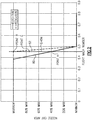
- One example schedule is illustrated in Figure 2 .
- Multiple data curves are provided, which correspond to different fan speeds.
- the curves which are linear in one example, provide first and second thresholds 80, 82 that respectively relate to upper and lower limits for the target variable area fan nozzle position as it relates to a range of air speeds.
- air speeds of between about 0.35 Mach and 0.55 Mach, and in one example, between about 0.38 Mach and 0.50 Mach provide a region in which the nozzle exit area is adjusted based upon fan speed. Below 0.35 Mach and above 0.55 Mach, the nozzle exit area is respectively at its maximum and minimum and the fan speed need not be used to determine the target variable area fan nozzle position.
- the fan speed is used to determine a target variable area fan nozzle position.
- the percent speed value represents the engine operating fan speed relative to the fan aerodynamic design speed (FEDS).
- the upper limit is defined at 60% of the FEDS, and the lower limit is defined at 75% of the FEDS.
- the upper and lower limits are defined respectively 65% and 70% of a particular fan speed. In the example of 0.45 Mach shown in Figure 2 , if the detected fan speed is above 70% of a particular fan speed, the target variable area fan nozzle position will be 40% of the maximum open position (point A). If the detected fan speed is less than 65% of a particular fan speed, the target variable area fan nozzle position will be at the maximum open position (point B in Figure 2 , second position P2 in Figure 1 ).
- the target variable area fan nozzle positions are averaged, for example. So, for a fan speed of 67% of a particular fan speed, the target variable area fan nozzle position is 75% of the maximum open position (point C). In this manner, the fan speed, or low speed spool rotational speed, is used to determine the target variable area fan nozzle position at a particular range of air speed.
- the controller 68 can include a processor, memory, and one or more input and/or output (I/O) device interface(s) that are communicatively coupled via a local interface.
- the local interface can include, for example but not limited to, one or more buses and/or other wired or wireless connections.
- the local interface may have additional elements, which are omitted for simplicity, such as controllers, buffers (caches), drivers, repeaters, and receivers to enable communications. Further, the local interface may include address, control, and/or data connections to enable appropriate communications among the aforementioned components.
- the controller 68 may be a hardware device for executing software, particularly software stored in memory.
- the controller 68 can be a custom made or commercially available processor, a central processing unit (CPU), an auxiliary processor among several processors associated with the computing device, a semiconductor based microprocessor (in the form of a microchip or chip set) or generally any device for executing software instructions.
- the memory can include any one or combination of volatile memory elements (e.g., random access memory (RAM, such as DRAM, SRAM, SDRAM, VRAM, etc.)) and/or nonvolatile memory elements (e.g., ROM, hard drive, tape, CD-ROM, etc.).
- volatile memory elements e.g., random access memory (RAM, such as DRAM, SRAM, SDRAM, VRAM, etc.)
- nonvolatile memory elements e.g., ROM, hard drive, tape, CD-ROM, etc.
- the memory may incorporate electronic, magnetic, optical, and/or other types of storage media.
- the memory can also have a distributed architecture, where various components are situated remotely from one another, but can be accessed by the processor.
- the software in the memory may include one or more separate programs, each of which includes an ordered listing of executable instructions for implementing logical functions.
- a system component embodied as software may also be construed as a source program, executable program (object code), script, or any other entity comprising a set of instructions to be performed.
- the program is translated via a compiler, assembler, interpreter, or the like, which may or may not be included within the memory.
- the Input/Output devices that may be coupled to system I/O Interface(s) may include input devices, for example but not limited to, a keyboard, mouse, scanner, microphone, camera, proximity device, etc. Further, the Input/Output devices may also include output devices, for example but not limited to, a printer, display, etc. Finally, the Input/Output devices may further include devices that communicate both as inputs and outputs, for instance but not limited to, a modulator/demodulator (modem; for accessing another device, system, or network), a radio frequency (RF) or other transceiver, a telephonic interface, a bridge, a router, etc.
- modem for accessing another device, system, or network
- RF radio frequency
- the controller 68 can be configured to execute software stored within the memory, to communicate data to and from the memory, and to generally control operations of the computing device pursuant to the software.
- Software in memory, in whole or in part, is read by the processor, perhaps buffered within the processor, and then executed.
Landscapes
- Engineering & Computer Science (AREA)
- Chemical & Material Sciences (AREA)
- Combustion & Propulsion (AREA)
- Mechanical Engineering (AREA)
- General Engineering & Computer Science (AREA)
- Physics & Mathematics (AREA)
- Fluid Mechanics (AREA)
- Structures Of Non-Positive Displacement Pumps (AREA)
Applications Claiming Priority (4)
| Application Number | Priority Date | Filing Date | Title |
|---|---|---|---|
| US201261592984P | 2012-01-31 | 2012-01-31 | |
| US13/365,455 US8869508B2 (en) | 2012-01-31 | 2012-02-03 | Gas turbine engine variable area fan nozzle control |
| PCT/US2013/022467 WO2013116034A1 (en) | 2012-01-31 | 2013-01-22 | Gas turbine engine variable area fan nozzle control |
| EP13743391.8A EP2809923B1 (de) | 2012-01-31 | 2013-01-22 | Steuerung eines gasturbinenmotors über eine verstellbare lüfterdüse |
Related Parent Applications (1)
| Application Number | Title | Priority Date | Filing Date |
|---|---|---|---|
| EP13743391.8A Division EP2809923B1 (de) | 2012-01-31 | 2013-01-22 | Steuerung eines gasturbinenmotors über eine verstellbare lüfterdüse |
Publications (1)
| Publication Number | Publication Date |
|---|---|
| EP3633166A1 true EP3633166A1 (de) | 2020-04-08 |
Family
ID=48869055
Family Applications (2)
| Application Number | Title | Priority Date | Filing Date |
|---|---|---|---|
| EP19211646.5A Withdrawn EP3633166A1 (de) | 2012-01-31 | 2013-01-22 | Steuerung eines gasturbinenmotors über eine verstellbare lüfterdüse |
| EP13743391.8A Active EP2809923B1 (de) | 2012-01-31 | 2013-01-22 | Steuerung eines gasturbinenmotors über eine verstellbare lüfterdüse |
Family Applications After (1)
| Application Number | Title | Priority Date | Filing Date |
|---|---|---|---|
| EP13743391.8A Active EP2809923B1 (de) | 2012-01-31 | 2013-01-22 | Steuerung eines gasturbinenmotors über eine verstellbare lüfterdüse |
Country Status (4)
| Country | Link |
|---|---|
| US (4) | US8869508B2 (de) |
| EP (2) | EP3633166A1 (de) |
| SG (1) | SG11201402941SA (de) |
| WO (1) | WO2013116034A1 (de) |
Families Citing this family (19)
| Publication number | Priority date | Publication date | Assignee | Title |
|---|---|---|---|---|
| US8869508B2 (en) * | 2012-01-31 | 2014-10-28 | United Technologies Corporation | Gas turbine engine variable area fan nozzle control |
| US10107191B2 (en) * | 2012-02-29 | 2018-10-23 | United Technologies Corporation | Geared gas turbine engine with reduced fan noise |
| US20160122005A1 (en) | 2013-03-11 | 2016-05-05 | United Technologies Corporation | Embedded engines in hybrid blended wing body |
| WO2015050619A2 (en) | 2013-08-20 | 2015-04-09 | United Technologies Corporation | High thrust geared gas turbine engine |
| GB2524774A (en) * | 2014-04-02 | 2015-10-07 | Rolls Royce Plc | Aircraft vapour trail control system |
| GB2524776B (en) * | 2014-04-02 | 2016-10-12 | Rolls Royce Plc | Aircraft vapour trail control system |
| FR3020658B1 (fr) * | 2014-04-30 | 2020-05-15 | Safran Aircraft Engines | Capot de recuperation d'huile de lubrification pour un equipement de turbomachine |
| US9869190B2 (en) | 2014-05-30 | 2018-01-16 | General Electric Company | Variable-pitch rotor with remote counterweights |
| US10072510B2 (en) | 2014-11-21 | 2018-09-11 | General Electric Company | Variable pitch fan for gas turbine engine and method of assembling the same |
| US9915225B2 (en) * | 2015-02-06 | 2018-03-13 | United Technologies Corporation | Propulsion system arrangement for turbofan gas turbine engine |
| US10100653B2 (en) | 2015-10-08 | 2018-10-16 | General Electric Company | Variable pitch fan blade retention system |
| US9803586B1 (en) * | 2016-05-31 | 2017-10-31 | The Boeing Company | Secondary systems and methods of control for variable area fan nozzles |
| US11203949B2 (en) * | 2016-08-11 | 2021-12-21 | General Electric Company | Mechanically driven air vehicle thermal management device |
| US11674435B2 (en) | 2021-06-29 | 2023-06-13 | General Electric Company | Levered counterweight feathering system |
| US11795964B2 (en) | 2021-07-16 | 2023-10-24 | General Electric Company | Levered counterweight feathering system |
| US12601271B2 (en) | 2022-10-21 | 2026-04-14 | General Electric Company | Variable pitch fan of a gas turbine engine |
| US12012901B1 (en) | 2023-02-17 | 2024-06-18 | General Electric Company | Turbomachinery engines with high-speed low-pressure turbines |
| US12398684B2 (en) | 2023-02-17 | 2025-08-26 | General Electric Company | Turbomachinery engines with high-speed low-pressure turbines |
| EP4417800A1 (de) | 2023-02-17 | 2024-08-21 | General Electric Company | Turbomaschinenmotoren mit hochgeschwindigkeitsniederdruckturbinen |
Citations (3)
| Publication number | Priority date | Publication date | Assignee | Title |
|---|---|---|---|---|
| US20040102890A1 (en) * | 2002-11-27 | 2004-05-27 | Brunell Brent Jerome | Methods and apparatus for model predictive control of aircraft gas turbine engines |
| US20110004388A1 (en) * | 2009-07-01 | 2011-01-06 | United Technologies Corporation | Turbofan temperature control with variable area nozzle |
| US20110052370A1 (en) * | 2009-09-02 | 2011-03-03 | United Technologies Corporation | Robust flow parameter model for component-level dynamic turbine system control |
Family Cites Families (129)
| Publication number | Priority date | Publication date | Assignee | Title |
|---|---|---|---|---|
| US2258792A (en) | 1941-04-12 | 1941-10-14 | Westinghouse Electric & Mfg Co | Turbine blading |
| GB579657A (en) | 1943-07-02 | 1946-08-12 | Power Jets Ltd | Improvements relating to aircraft propulsion installations and landing gear |
| US2469375A (en) | 1945-09-24 | 1949-05-10 | Westinghouse Electric Corp | Deicing apparatus for compressors |
| US2663993A (en) | 1945-10-10 | 1953-12-29 | Westinghouse Electric Corp | Deicing apparatus |
| US3021731A (en) | 1951-11-10 | 1962-02-20 | Wilhelm G Stoeckicht | Planetary gear transmission |
| US2936655A (en) | 1955-11-04 | 1960-05-17 | Gen Motors Corp | Self-aligning planetary gearing |
| US3194487A (en) | 1963-06-04 | 1965-07-13 | United Aircraft Corp | Noise abatement method and apparatus |
| US3295316A (en) * | 1964-06-10 | 1967-01-03 | United Aircraft Corp | Speed overshoot limiter for fuel controls |
| US3287906A (en) | 1965-07-20 | 1966-11-29 | Gen Motors Corp | Cooled gas turbine vanes |
| US3352178A (en) | 1965-11-15 | 1967-11-14 | Gen Motors Corp | Planetary gearing |
| US3412560A (en) | 1966-08-03 | 1968-11-26 | Gen Motors Corp | Jet propulsion engine with cooled combustion chamber, fuel heater, and induced air-flow |
| US3599873A (en) * | 1969-09-15 | 1971-08-17 | United Aircraft Corp | Variable area exhaust nozzle construction |
| US3664612A (en) | 1969-12-22 | 1972-05-23 | Boeing Co | Aircraft engine variable highlight inlet |
| US3622075A (en) | 1970-03-16 | 1971-11-23 | Boeing Co | Self-actuating variable area acoustic jet engine exhaust nozzle |
| GB1350431A (en) | 1971-01-08 | 1974-04-18 | Secr Defence | Gearing |
| US3892358A (en) | 1971-03-17 | 1975-07-01 | Gen Electric | Nozzle seal |
| US3765623A (en) | 1971-10-04 | 1973-10-16 | Mc Donnell Douglas Corp | Air inlet |
| US3747343A (en) | 1972-02-10 | 1973-07-24 | United Aircraft Corp | Low noise prop-fan |
| GB1418905A (en) | 1972-05-09 | 1975-12-24 | Rolls Royce | Gas turbine engines |
| US3843277A (en) | 1973-02-14 | 1974-10-22 | Gen Electric | Sound attenuating inlet duct |
| US3988889A (en) * | 1974-02-25 | 1976-11-02 | General Electric Company | Cowling arrangement for a turbofan engine |
| US3932058A (en) | 1974-06-07 | 1976-01-13 | United Technologies Corporation | Control system for variable pitch fan propulsor |
| US3935558A (en) | 1974-12-11 | 1976-01-27 | United Technologies Corporation | Surge detector for turbine engines |
| US4068469A (en) | 1975-05-29 | 1978-01-17 | The United States Of America As Represented By The Administrator Of The National Aeronautics And Space Administration | Variable thrust nozzle for quiet turbofan engine and method of operating same |
| US4130872A (en) * | 1975-10-10 | 1978-12-19 | The United States Of America As Represented By The Secretary Of The Air Force | Method and system of controlling a jet engine for avoiding engine surge |
| US4159625A (en) | 1977-02-01 | 1979-07-03 | United Technologies Corporation | Control for gas turbine engine |
| GB1516041A (en) | 1977-02-14 | 1978-06-28 | Secr Defence | Multistage axial flow compressor stators |
| US4240250A (en) | 1977-12-27 | 1980-12-23 | The Boeing Company | Noise reducing air inlet for gas turbine engines |
| US4242864A (en) | 1978-05-25 | 1981-01-06 | The United States Of America As Represented By The Administrator Of The National Aeronautics And Space Administration | Integrated control system for a gas turbine engine |
| GB2041090A (en) | 1979-01-31 | 1980-09-03 | Rolls Royce | By-pass gas turbine engines |
| US4284174A (en) | 1979-04-18 | 1981-08-18 | Avco Corporation | Emergency oil/mist system |
| US4220171A (en) | 1979-05-14 | 1980-09-02 | The United States Of America As Represented By The Administrator Of The National Aeronautics And Space Administration | Curved centerline air intake for a gas turbine engine |
| US4289360A (en) | 1979-08-23 | 1981-09-15 | General Electric Company | Bearing damper system |
| DE2940446C2 (de) | 1979-10-05 | 1982-07-08 | B. Braun Melsungen Ag, 3508 Melsungen | Züchtung von tierischen Zellen in Suspensions- und Monolayerkulturen in Fermentationsgefäßen |
| US4397431A (en) | 1981-11-02 | 1983-08-09 | Avco Corporation | Fail-safe, anti-icing system for aircraft engines |
| US4478551A (en) | 1981-12-08 | 1984-10-23 | United Technologies Corporation | Turbine exhaust case design |
| US4722357A (en) | 1986-04-11 | 1988-02-02 | United Technologies Corporation | Gas turbine engine nacelle |
| US4696156A (en) | 1986-06-03 | 1987-09-29 | United Technologies Corporation | Fuel and oil heat management system for a gas turbine engine |
| US4979362A (en) | 1989-05-17 | 1990-12-25 | Sundstrand Corporation | Aircraft engine starting and emergency power generating system |
| US5005015A (en) | 1989-08-07 | 1991-04-02 | General Electric Company | Ice detection system |
| US5058617A (en) | 1990-07-23 | 1991-10-22 | General Electric Company | Nacelle inlet for an aircraft gas turbine engine |
| US5141400A (en) | 1991-01-25 | 1992-08-25 | General Electric Company | Wide chord fan blade |
| US5102379A (en) | 1991-03-25 | 1992-04-07 | United Technologies Corporation | Journal bearing arrangement |
| US5282719A (en) | 1991-05-13 | 1994-02-01 | Alliedsignal Inc. | Quad mode fan pitch actuation system for a gas turbine engine |
| US5257498A (en) | 1992-04-23 | 1993-11-02 | United Technologies Corporation | Efficient anti-ice exhaust vent |
| US5317877A (en) | 1992-08-03 | 1994-06-07 | General Electric Company | Intercooled turbine blade cooling air feed system |
| US5261227A (en) | 1992-11-24 | 1993-11-16 | General Electric Company | Variable specific thrust turbofan engine |
| US5447411A (en) | 1993-06-10 | 1995-09-05 | Martin Marietta Corporation | Light weight fan blade containment system |
| US5466198A (en) | 1993-06-11 | 1995-11-14 | United Technologies Corporation | Geared drive system for a bladed propulsor |
| US5361580A (en) | 1993-06-18 | 1994-11-08 | General Electric Company | Gas turbine engine rotor support system |
| US5524847A (en) | 1993-09-07 | 1996-06-11 | United Technologies Corporation | Nacelle and mounting arrangement for an aircraft engine |
| RU2082824C1 (ru) | 1994-03-10 | 1997-06-27 | Московский государственный авиационный институт (технический университет) | Способ защиты жаропрочных материалов от воздействия агрессивных сред высокоскоростных газовых потоков (варианты) |
| US5433674A (en) | 1994-04-12 | 1995-07-18 | United Technologies Corporation | Coupling system for a planetary gear train |
| US5778659A (en) | 1994-10-20 | 1998-07-14 | United Technologies Corporation | Variable area fan exhaust nozzle having mechanically separate sleeve and thrust reverser actuation systems |
| WO1997000381A1 (en) | 1994-12-14 | 1997-01-03 | United Technologies Corporation | Compressor stall and surge control using airflow asymmetry measurement |
| FR2742482B1 (fr) * | 1995-12-19 | 1998-02-06 | Hurel Dubois Avions | Inverseur de poussee a tuyere a section reglable pour moteur d'avion a reaction |
| JP2969075B2 (ja) | 1996-02-26 | 1999-11-02 | ジャパンゴアテックス株式会社 | 脱気装置 |
| US5634767A (en) | 1996-03-29 | 1997-06-03 | General Electric Company | Turbine frame having spindle mounted liner |
| US5857836A (en) | 1996-09-10 | 1999-01-12 | Aerodyne Research, Inc. | Evaporatively cooled rotor for a gas turbine engine |
| US5833140A (en) | 1996-12-12 | 1998-11-10 | United Technologies Corporation | Variable geometry exhaust nozzle for a turbine engine |
| US5975841A (en) | 1997-10-03 | 1999-11-02 | Thermal Corp. | Heat pipe cooling for turbine stators |
| US5985470A (en) | 1998-03-16 | 1999-11-16 | General Electric Company | Thermal/environmental barrier coating system for silicon-based materials |
| US6517341B1 (en) | 1999-02-26 | 2003-02-11 | General Electric Company | Method to prevent recession loss of silica and silicon-containing materials in combustion gas environments |
| US6410148B1 (en) | 1999-04-15 | 2002-06-25 | General Electric Co. | Silicon based substrate with environmental/ thermal barrier layer |
| US6315815B1 (en) | 1999-12-16 | 2001-11-13 | United Technologies Corporation | Membrane based fuel deoxygenator |
| US6223616B1 (en) | 1999-12-22 | 2001-05-01 | United Technologies Corporation | Star gear system with lubrication circuit and lubrication method therefor |
| US6318070B1 (en) | 2000-03-03 | 2001-11-20 | United Technologies Corporation | Variable area nozzle for gas turbine engines driven by shape memory alloy actuators |
| US6444335B1 (en) | 2000-04-06 | 2002-09-03 | General Electric Company | Thermal/environmental barrier coating for silicon-containing materials |
| EP1780387A3 (de) | 2000-09-05 | 2007-07-18 | Sudarshan Paul Dev | Kompaktgasturbine |
| US6708482B2 (en) | 2001-11-29 | 2004-03-23 | General Electric Company | Aircraft engine with inter-turbine engine frame |
| US6607165B1 (en) | 2002-06-28 | 2003-08-19 | General Electric Company | Aircraft engine mount with single thrust link |
| US6814541B2 (en) | 2002-10-07 | 2004-11-09 | General Electric Company | Jet aircraft fan case containment design |
| US7021042B2 (en) | 2002-12-13 | 2006-04-04 | United Technologies Corporation | Geartrain coupling for a turbofan engine |
| US6892127B2 (en) * | 2003-02-28 | 2005-05-10 | General Electric Company | Methods and apparatus for assessing gas turbine engine damage |
| US6709492B1 (en) | 2003-04-04 | 2004-03-23 | United Technologies Corporation | Planar membrane deoxygenator |
| US7175136B2 (en) | 2003-04-16 | 2007-02-13 | The Boeing Company | Method and apparatus for detecting conditions conducive to ice formation |
| US7631483B2 (en) * | 2003-09-22 | 2009-12-15 | General Electric Company | Method and system for reduction of jet engine noise |
| CA2456563C (en) | 2004-01-30 | 2011-12-20 | Pratt & Whitney Canada Corp. | Anti-icing apparatus and method for aero-engine nose cone |
| DE102004016246A1 (de) | 2004-04-02 | 2005-10-20 | Mtu Aero Engines Gmbh | Turbine, insbesondere Niederdruckturbine, einer Gasturbine, insbesondere eines Flugtriebwerks |
| US7328580B2 (en) | 2004-06-23 | 2008-02-12 | General Electric Company | Chevron film cooled wall |
| US7826954B2 (en) * | 2004-06-25 | 2010-11-02 | Honda Motor Co., Ltd. | System for monitoring sensor outputs of a gas turbine engine |
| US7174704B2 (en) * | 2004-07-23 | 2007-02-13 | General Electric Company | Split shroud exhaust nozzle |
| FR2875542B1 (fr) | 2004-09-21 | 2009-02-13 | Airbus France Sas | Dispositif de protection contre le givrage pour moteurs d'aeronefs et procedes de degivrage associe |
| US7845902B2 (en) * | 2005-02-15 | 2010-12-07 | Massachusetts Institute Of Technology | Jet engine inlet-fan system and design method |
| GB0506685D0 (en) | 2005-04-01 | 2005-05-11 | Hopkins David R | A design to increase and smoothly improve the throughput of fluid (air or gas) through the inlet fan (or fans) of an aero-engine system |
| US7374403B2 (en) | 2005-04-07 | 2008-05-20 | General Electric Company | Low solidity turbofan |
| US7469862B2 (en) | 2005-04-22 | 2008-12-30 | Goodrich Corporation | Aircraft engine nacelle inlet having access opening for electrical ice protection system |
| DE102006031330B4 (de) | 2005-07-14 | 2014-03-20 | Goodrich Corp. | Für Eis empfänglicher Abschnitt eines Flugzeugs, insbesondere Flugtriebwerk- Zelleneinlasslippe, umfassend ein Eisschutzsystem, Flugtriebwerk mit einer solchen Einlasslippe sowie ein Verfahren zum Schutz einer solchen Einlasslippe vor Vereisung |
| EP1928952B1 (de) | 2005-09-28 | 2014-07-09 | Entrotech Composites, LLC. | Gewebeverstärkte verbundstoffe und verfahren zu deren zubereitung |
| US7591754B2 (en) | 2006-03-22 | 2009-09-22 | United Technologies Corporation | Epicyclic gear train integral sun gear coupling design |
| BE1017135A3 (nl) | 2006-05-11 | 2008-03-04 | Hansen Transmissions Int | Een tandwielkast voor een windturbine. |
| US20080003096A1 (en) | 2006-06-29 | 2008-01-03 | United Technologies Corporation | High coverage cooling hole shape |
| JP4911344B2 (ja) | 2006-07-04 | 2012-04-04 | 株式会社Ihi | ターボファンエンジン |
| US7926260B2 (en) | 2006-07-05 | 2011-04-19 | United Technologies Corporation | Flexible shaft for gas turbine engine |
| US8585538B2 (en) | 2006-07-05 | 2013-11-19 | United Technologies Corporation | Coupling system for a star gear train in a gas turbine engine |
| US7694505B2 (en) | 2006-07-31 | 2010-04-13 | General Electric Company | Gas turbine engine assembly and method of assembling same |
| US7632064B2 (en) | 2006-09-01 | 2009-12-15 | United Technologies Corporation | Variable geometry guide vane for a gas turbine engine |
| US8209950B2 (en) | 2006-10-12 | 2012-07-03 | United Technologies Corporation | Detecting ice buildup on an aircraft engine and actuating the turbofan exit nozzle to break the ice |
| US8365513B2 (en) | 2006-10-12 | 2013-02-05 | United Technologies Corporation | Turbofan engine operation control |
| WO2008045074A1 (en) | 2006-10-12 | 2008-04-17 | United Technologies Corporation | Turbofan engine with variable bypass nozzle exit area and method of operation |
| WO2008045050A1 (en) * | 2006-10-12 | 2008-04-17 | United Technologies Corporation | Gas turbine engine with fan variable area nozzle, nacelle assembly and method of varying area of a fan nozzle |
| WO2008063154A2 (en) | 2006-10-12 | 2008-05-29 | United Technologies Corporation | Fan variable area nozzle with adaptive structure |
| US7662059B2 (en) | 2006-10-18 | 2010-02-16 | United Technologies Corporation | Lubrication of windmilling journal bearings |
| US8020665B2 (en) | 2006-11-22 | 2011-09-20 | United Technologies Corporation | Lubrication system with extended emergency operability |
| FR2910937B1 (fr) | 2007-01-02 | 2009-04-03 | Airbus France Sas | Nacelle de reacteur d'aeronef et aeronef comportant une telle nacelle |
| US20090067993A1 (en) | 2007-03-22 | 2009-03-12 | Roberge Gary D | Coated variable area fan nozzle |
| US8017188B2 (en) | 2007-04-17 | 2011-09-13 | General Electric Company | Methods of making articles having toughened and untoughened regions |
| US20080257033A1 (en) | 2007-04-20 | 2008-10-23 | Shadin, L.P. | Ice detection |
| US7950237B2 (en) | 2007-06-25 | 2011-05-31 | United Technologies Corporation | Managing spool bearing load using variable area flow nozzle |
| US9062500B2 (en) | 2007-07-20 | 2015-06-23 | Schlumberger Technology Corporation | System and method to facilitate interventions from an offshore platform |
| US7762081B2 (en) | 2007-07-25 | 2010-07-27 | Honeywell International Inc. | Compressor inlet guide vane de-ice control system and method |
| US20120124964A1 (en) | 2007-07-27 | 2012-05-24 | Hasel Karl L | Gas turbine engine with improved fuel efficiency |
| US8256707B2 (en) | 2007-08-01 | 2012-09-04 | United Technologies Corporation | Engine mounting configuration for a turbofan gas turbine engine |
| EP2479414B1 (de) | 2007-08-08 | 2015-06-10 | Rohr, Inc. | Verstellbare Fandüse mit Bypass-Strom |
| US8205432B2 (en) | 2007-10-03 | 2012-06-26 | United Technologies Corporation | Epicyclic gear train for turbo fan engine |
| US7837150B2 (en) | 2007-12-21 | 2010-11-23 | Rohr, Inc. | Ice protection system for a multi-segment aircraft component |
| DE102008024022A1 (de) * | 2008-05-16 | 2009-11-19 | Rolls-Royce Deutschland Ltd & Co Kg | Gasturbinentriebwerk, insbesondere Flugtriebwerk |
| GB0809759D0 (en) * | 2008-05-30 | 2008-07-09 | Rolls Royce Plc | Gas turbine engine |
| US8128021B2 (en) | 2008-06-02 | 2012-03-06 | United Technologies Corporation | Engine mount system for a turbofan gas turbine engine |
| US7997868B1 (en) | 2008-11-18 | 2011-08-16 | Florida Turbine Technologies, Inc. | Film cooling hole for turbine airfoil |
| US8092153B2 (en) | 2008-12-16 | 2012-01-10 | Pratt & Whitney Canada Corp. | Bypass air scoop for gas turbine engine |
| US8307626B2 (en) | 2009-02-26 | 2012-11-13 | United Technologies Corporation | Auxiliary pump system for fan drive gear system |
| US8181441B2 (en) | 2009-02-27 | 2012-05-22 | United Technologies Corporation | Controlled fan stream flow bypass |
| US8172716B2 (en) | 2009-06-25 | 2012-05-08 | United Technologies Corporation | Epicyclic gear system with superfinished journal bearing |
| US8443586B2 (en) * | 2009-11-24 | 2013-05-21 | United Technologies Corporation | Variable area fan nozzle bearing track |
| US9170616B2 (en) | 2009-12-31 | 2015-10-27 | Intel Corporation | Quiet system cooling using coupled optimization between integrated micro porous absorbers and rotors |
| US8905713B2 (en) | 2010-05-28 | 2014-12-09 | General Electric Company | Articles which include chevron film cooling holes, and related processes |
| US9593628B2 (en) | 2012-01-31 | 2017-03-14 | United Technologies Corporation | Gas turbine engine variable area fan nozzle with ice management |
| US8869508B2 (en) * | 2012-01-31 | 2014-10-28 | United Technologies Corporation | Gas turbine engine variable area fan nozzle control |
-
2012
- 2012-02-03 US US13/365,455 patent/US8869508B2/en active Active
-
2013
- 2013-01-22 EP EP19211646.5A patent/EP3633166A1/de not_active Withdrawn
- 2013-01-22 SG SG11201402941SA patent/SG11201402941SA/en unknown
- 2013-01-22 EP EP13743391.8A patent/EP2809923B1/de active Active
- 2013-01-22 WO PCT/US2013/022467 patent/WO2013116034A1/en not_active Ceased
-
2014
- 2014-09-30 US US14/502,354 patent/US10006406B2/en active Active
-
2018
- 2018-06-24 US US16/016,636 patent/US10830178B2/en active Active
-
2020
- 2020-09-30 US US17/038,322 patent/US11401889B2/en active Active
Patent Citations (3)
| Publication number | Priority date | Publication date | Assignee | Title |
|---|---|---|---|---|
| US20040102890A1 (en) * | 2002-11-27 | 2004-05-27 | Brunell Brent Jerome | Methods and apparatus for model predictive control of aircraft gas turbine engines |
| US20110004388A1 (en) * | 2009-07-01 | 2011-01-06 | United Technologies Corporation | Turbofan temperature control with variable area nozzle |
| US20110052370A1 (en) * | 2009-09-02 | 2011-03-03 | United Technologies Corporation | Robust flow parameter model for component-level dynamic turbine system control |
Also Published As
| Publication number | Publication date |
|---|---|
| US8869508B2 (en) | 2014-10-28 |
| SG11201402941SA (en) | 2014-08-28 |
| US20130192241A1 (en) | 2013-08-01 |
| WO2013116034A1 (en) | 2013-08-08 |
| EP2809923A4 (de) | 2015-10-07 |
| EP2809923B1 (de) | 2019-11-27 |
| US11401889B2 (en) | 2022-08-02 |
| US10830178B2 (en) | 2020-11-10 |
| EP2809923A1 (de) | 2014-12-10 |
| US20150315976A1 (en) | 2015-11-05 |
| US10006406B2 (en) | 2018-06-26 |
| US20210062763A1 (en) | 2021-03-04 |
| US20190003422A1 (en) | 2019-01-03 |
Similar Documents
| Publication | Publication Date | Title |
|---|---|---|
| US11401889B2 (en) | Gas turbine engine variable area fan nozzle control | |
| US9097133B2 (en) | Compressor tip clearance management for a gas turbine engine | |
| US10578053B2 (en) | Gas turbine engine variable area fan nozzle with ice management | |
| US8862362B2 (en) | Scheduling of variable area fan nozzle to optimize engine performance | |
| CA2882565C (en) | Pylon matched fan exit guide vane for noise reduction in a geared turbofan engine | |
| EP2098704B1 (de) | Managementsystem des Fanflatterns in einem Turbofan mit variablem Fandüsenquerschnitt | |
| US20120124965A1 (en) | Variable area fan nozzle fan flutter management system | |
| US11773743B2 (en) | Model-based rotor speed keep out zone control | |
| US20160153865A1 (en) | Gas turbine engine airfoil growth inspection method | |
| EP3141725B1 (de) | Steuerungssystem und verfahren zur steuerung eines gasturbinenmotors mit variablem bereich | |
| EP2809930B1 (de) | Gasturbine mit einer variablen Austrittsdüse zur Handhabung von Gebläseflatterschwingungen |
Legal Events
| Date | Code | Title | Description |
|---|---|---|---|
| PUAI | Public reference made under article 153(3) epc to a published international application that has entered the european phase |
Free format text: ORIGINAL CODE: 0009012 |
|
| STAA | Information on the status of an ep patent application or granted ep patent |
Free format text: STATUS: THE APPLICATION HAS BEEN PUBLISHED |
|
| AC | Divisional application: reference to earlier application |
Ref document number: 2809923 Country of ref document: EP Kind code of ref document: P |
|
| AK | Designated contracting states |
Kind code of ref document: A1 Designated state(s): AL AT BE BG CH CY CZ DE DK EE ES FI FR GB GR HR HU IE IS IT LI LT LU LV MC MK MT NL NO PL PT RO RS SE SI SK SM TR |
|
| STAA | Information on the status of an ep patent application or granted ep patent |
Free format text: STATUS: THE APPLICATION IS DEEMED TO BE WITHDRAWN |
|
| 18D | Application deemed to be withdrawn |
Effective date: 20201009 |