EP3633196B1 - Mesure du mouvement verticale - Google Patents
Mesure du mouvement verticale Download PDFInfo
- Publication number
- EP3633196B1 EP3633196B1 EP18197883.4A EP18197883A EP3633196B1 EP 3633196 B1 EP3633196 B1 EP 3633196B1 EP 18197883 A EP18197883 A EP 18197883A EP 3633196 B1 EP3633196 B1 EP 3633196B1
- Authority
- EP
- European Patent Office
- Prior art keywords
- acceleration sensor
- component
- evaluation device
- arrangement according
- valve
- Prior art date
- Legal status (The legal status is an assumption and is not a legal conclusion. Google has not performed a legal analysis and makes no representation as to the accuracy of the status listed.)
- Active
Links
Images


Classifications
-
- F—MECHANICAL ENGINEERING; LIGHTING; HEATING; WEAPONS; BLASTING
- F04—POSITIVE - DISPLACEMENT MACHINES FOR LIQUIDS; PUMPS FOR LIQUIDS OR ELASTIC FLUIDS
- F04B—POSITIVE-DISPLACEMENT MACHINES FOR LIQUIDS; PUMPS
- F04B49/00—Control, e.g. of pump delivery, or pump pressure of, or safety measures for, machines, pumps, or pumping installations, not otherwise provided for, or of interest apart from, groups F04B1/00 - F04B47/00
- F04B49/06—Control using electricity
- F04B49/065—Control using electricity and making use of computers
-
- F—MECHANICAL ENGINEERING; LIGHTING; HEATING; WEAPONS; BLASTING
- F04—POSITIVE - DISPLACEMENT MACHINES FOR LIQUIDS; PUMPS FOR LIQUIDS OR ELASTIC FLUIDS
- F04B—POSITIVE-DISPLACEMENT MACHINES FOR LIQUIDS; PUMPS
- F04B2201/00—Pump parameters
- F04B2201/02—Piston parameters
- F04B2201/0201—Position of the piston
-
- F—MECHANICAL ENGINEERING; LIGHTING; HEATING; WEAPONS; BLASTING
- F04—POSITIVE - DISPLACEMENT MACHINES FOR LIQUIDS; PUMPS FOR LIQUIDS OR ELASTIC FLUIDS
- F04B—POSITIVE-DISPLACEMENT MACHINES FOR LIQUIDS; PUMPS
- F04B2201/00—Pump parameters
- F04B2201/02—Piston parameters
- F04B2201/0202—Linear speed of the piston
-
- F—MECHANICAL ENGINEERING; LIGHTING; HEATING; WEAPONS; BLASTING
- F04—POSITIVE - DISPLACEMENT MACHINES FOR LIQUIDS; PUMPS FOR LIQUIDS OR ELASTIC FLUIDS
- F04B—POSITIVE-DISPLACEMENT MACHINES FOR LIQUIDS; PUMPS
- F04B2201/00—Pump parameters
- F04B2201/02—Piston parameters
- F04B2201/0203—Acceleration of the piston
-
- F—MECHANICAL ENGINEERING; LIGHTING; HEATING; WEAPONS; BLASTING
- F04—POSITIVE - DISPLACEMENT MACHINES FOR LIQUIDS; PUMPS FOR LIQUIDS OR ELASTIC FLUIDS
- F04B—POSITIVE-DISPLACEMENT MACHINES FOR LIQUIDS; PUMPS
- F04B2201/00—Pump parameters
- F04B2201/02—Piston parameters
- F04B2201/0207—Number of pumping strokes in unit time
Definitions
- the invention relates to detecting and/or controlling the position of a flow-guiding unit.
- the flow-guiding unit can be, for example, a fitting or a pump, in particular a diaphragm pump.
- Faucets have two main functions. On the one hand, they are used to regulate the flow, with valves being used in particular for regulating the quantity, with which a very fine adjustment of the stroke is possible.
- fittings are also used as so-called switching fittings, which are usually used completely open or completely closed.
- switching fittings can be designed, for example, as cocks, slides or flaps.
- the stroke can either be recorded continuously or the position of the respective valve can be recorded in its end positions, i.e. completely open or completely closed.
- a limit switch box can be attached to the actuator housing on valves.
- a switching piece can be connected to a piston rod which is connected to the shut-off body of the fitting. Movement of the piston rod releases a movement of the contact piece.
- a proximity switch can be damped for completely open or completely closed. This can happen, for example, when a metal object approaches a field and damping then occurs in an oscillating circuit. If the damping exceeds a threshold value, a signal is triggered.
- an upper area of the box which is attached to the drive housing, is used for the electrical connection of a proximity switch to a corresponding process control device.
- a proximity switch to a corresponding process control device.
- the position of a flow-guiding unit is often detected by means of position detection using potentiometers, coil arrays or Hall sensors.
- a microcontroller evaluates an analog signal, which is then digitized. The open and closed positions are stored and the actual value of the respective sensor is compared with the stored positions. When one of the two end positions is reached, the output is switched open or closed via the microcontroller.
- the position controller includes a position transmitter for detecting the actual position of an actuator. Furthermore, the position controller includes a controller unit for comparing the actual position with a predefinable target position to generate an actuating signal.
- a magnet with a magneto-restrictive sensor is provided as a position transmitter.
- a GMR sensor is preferably used in this case.
- the DE 103 60 434 B4 relates to an arrangement for detecting the position of a component that can be driven by an actuator, such as a valve rod.
- the arrangement includes a position sensor housed in a controller housing.
- the arrangement also includes a movable movement representative, via which an actuating movement of the component is transmitted to the sensor. Wherein the position of the component is recorded via the position of the movement representative. Actuating movement forces are transmitted from the component to the movement representative without contact.
- the EP 0 961 066 B1 relates to a freely programmable position indicator device. This is used in particular for valves.
- the device includes a moveable actuator and a position detection device as well as an electronic evaluation device.
- the position detection device is assigned to the actuator and constantly detects the position of the actuator while generating an analog output signal.
- the output signal from the position detection device is forwarded to the electronic evaluation device for determining a position indicator.
- the position indicator device is designed in such a way that the position indicator device can be freely programmed by activating a microswitch.
- the recorded positions are stored in the evaluation device.
- the device has magnetostrictive sensors.
- the position of valves can be detected via the sensors.
- the device comprises a housing with an actuating means arranged movably therein. Furthermore, the device comprises a spring arranged on the housing. A spring force is applied to the actuating means.
- a position detection device is located in the upper part of the housing. The upper part of the housing also has a support plate with a housing for the actuating means and an outer housing. The adjusting means and the spring are arranged within the adjusting means housing.
- WO 2014 165831 discloses a hydraulic pump with a position sensor attached to the piston rod.
- the object of the invention is to specify an arrangement for detecting and/or controlling the position of a flow-guiding unit, which precisely and quickly detects the position of a flow-guiding unit.
- the arrangement should be able to detect both the end positions and intermediate positions when opening or closing the flow-guiding unit.
- the arrangement should be characterized by simple assembly and reliable operation.
- the arrangement should take up as little installation space as possible.
- the possibility should be given of detecting and processing other variables, possibly also in combination with the stroke, in addition to the detection of the stroke.
- the arrangement should be characterized by an inexpensive production method and low operating costs.
- a component connected to a drive of the flow-guiding unit has an acceleration sensor.
- the acceleration sensor is connected to an evaluation device.
- the acceleration sensor is preferably an element which has a mass, with inertial forces which act on the mass preferably being determined.
- the acceleration can be deduced from an evaluation of the force measurement.
- a speed-time function can be determined from an acceleration-time function by integrating the acceleration.
- a distance-time function can be calculated from the speed-time function by further integration. The distance-time function is evaluated using reference values in such a way that a statement about the position of the flow-guiding unit is made possible.
- stroke counting can also take place.
- a great advantage of the invention is that the system can be used without mechanical adaptation.
- the sensor is attached to a component or integrated into a component, with a rod preferably being suitable for this purpose. Since no mechanical adaptation is required with the arrangement according to the invention, a significantly smaller installation space is required than with conventional solutions. Costs are saved by eliminating the need for adaptation.
- the component that has the acceleration sensor is connected to a shut-off element.
- the component can be a piston rod that is connected to a shut-off body of a valve. With a linear movement of the piston rod, the position of the shut-off body can be changed and the throughflow of the flow-guiding device can thus be regulated.
- the position of the shut-off body can be determined very precisely on the one hand in order to create a metering option, and on the other hand a rough position determination is particularly suitable for detecting the end positions, i.e. the "OPEN" and "CLOSED" positions of a shut-off element.
- the cumulative stroke distance over time provides an approach to wear detection. In this way, forecasts can initially be made for the service life of a membrane in a specific area of application. At the same time, however, data can also be recorded that can be used to improve future forecasts.
- the acceleration sensor can be connected to the evaluation unit with cables.
- the acceleration sensor is wirelessly connected to the evaluation device.
- a short-range radio system in particular an RFID system and/or a Bluetooth system, is preferably used.
- the wireless connection of the acceleration sensor to the evaluation unit saves installation space. Furthermore, a flexible positioning of the evaluation device is made possible. Thus, in contrast to the prior art, it is no longer absolutely necessary for the evaluation device to be arranged on the drive, for example.
- the evaluation unit can also be positioned at other points, for example on a device for guiding the medium, in particular on a pipeline. This also enables the acquisition of other measured variables.
- the evaluation device has additional sensors, temperature sensors in particular proving to be advantageous.
- additional sensors By determining further data via additional sensors, statements can be made alone or in combination with the signals from the acceleration sensor on the operating state of the flow-guiding unit or the medium.
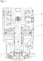
- a flow-carrying unit 2 is installed in a pipeline 1 of a system, not shown.
- the flow-guiding unit 2 is shown in FIG figure 1 embodied as a valve that regulates the flow of a medium 5 via a corresponding stroke of an element 4 that interacts with a valve seat 3 .
- the lifting movement is generated by a drive 6 and transmitted to the element 4 by means of a component 7 .
- component 7 is designed as a rod and element 4 as a shut-off body.
- a pneumatic drive 6 is shown purely as an example. However, an electric drive 6 is preferably used in the invention.
- FIG. 1 a variant of the invention is shown in which a connection to an evaluation device 8 is established via a cable 9 .
- the cable 9 carries out the movements of the component 7 at least partially.
- the evaluation device 8 compares the actual position of the component 7 obtained with the signal with a desired value supplied from a field bus 11 via a data interface 10 and corrects the system deviation.
- FIG figure 2 shows a sectional view of a component 7, connected to a drive 6, of a flow-guiding unit 2.
- the drive 6 acts as a linear drive.
- the component 7 has an acceleration sensor 12 .
- the acceleration sensor 12 or acceleration pick-up is attached to the component 7 designed as a piston rod.
- the acceleration sensor 12 can be glued on or arranged with fastening means on the surface of the piston rod.
- the acceleration sensor 12 can also be integrated into the component 7 .
- the acceleration sensor 12 has a system with which wireless transmission of the sensor signals is possible. This is preferably a short-range radio system. For example, an RFID system or a Bluetooth LE system can be used.
- the sensor signals are transmitted to an evaluation device 8, which is figure 2 is not shown.
- the evaluation device 8 can also be used as a control or regulating device.
- the acceleration sensor 12 acts as a position transmitter for detecting the actual position of an actuator and interacts with the evaluation device 8 designed as a control unit to compare the actual position with a predeterminable desired position to generate an actuating signal.
- the evaluation device 8 evaluates the signals from the acceleration sensor 12 .
- the path of the acceleration sensor 12 can be calculated by double integration of the acceleration.
- the acceleration sensor 12 can also be used as a stroke counter.
- the system can be used without mechanical adaptation. It only has to be attached to component 7. By doing without a mechanical adaptation, the installation space is significantly smaller than with conventional, state-of-the-art solutions. Costs can also be saved by eliminating the adaptation.
- an additional radio module is preferably used an additional radio module.
- the energy supply of the radio module can be generated by a battery, a rechargeable battery or "energy harvesting".
- energy harvesting refers to the extraction of small amounts of electrical energy from sources such as ambient temperature, vibration or air currents for low-power mobile devices.
- Nano generators are preferably used for this purpose.
- FIG figure 3 shows different variants of the arrangement of the evaluation device 8.
- the evaluation device 8 can be seated on the drive 6, for example.
- the evaluation device 8 is arranged on a device 13 for guiding the medium 5 .
- the device 13 is as shown in FIG figure 3 around a pipeline. Due to the possibility of positioning the evaluation device 8 on a pipeline, the temperature profile of the medium 5 can also be determined cost-effectively, for example. Together with other measured values, it is therefore possible to collect important information in order to determine statements about the expected service life of the flow-guiding unit. In particular, in the case of a diaphragm pump or a diaphragm valve, for example, statements can be made about the service life of the diaphragm used.
- the arrangement according to the invention enables a flexible position of the evaluation device 8.
Landscapes
- Engineering & Computer Science (AREA)
- Computer Hardware Design (AREA)
- Mechanical Engineering (AREA)
- General Engineering & Computer Science (AREA)
- Indication Of The Valve Opening Or Closing Status (AREA)
Claims (11)
- Ensemble destiné à détecter et/ou réguler la position d'une vanne (2), caractérisé en ce qu'un composant (7), relié à un entraînement (6), comporte un capteur d'accélération (12) qui est relié à un moyen d'évaluation (8), le composant (7) étant conçu comme une tige de piston et le capteur d'accélération étant intégré dans la tige de piston, le composant qui comporte le capteur d'accélération étant relié à un élément de blocage, un mouvement linéaire de la tige de piston modifiant la position du corps de blocage et régulant le débit.
- Ensemble selon la revendication 1, caractérisé en ce que le composant (7) est relié à un élément (4), l'élément (4) étant de préférence réalisé comme un élément de blocage.
- Ensemble selon l'une des revendications 1 ou 2, caractérisé en ce que le capteur d'accélération (12) est relié sans fil au moyen d'évaluation (8), notamment par le biais d'un système radio à courte portée, de préférence un système RFID et/ou un système Bluetooth.
- Ensemble selon l'une des revendications 1 à 3, caractérisé en ce que le capteur d'accélération (12) est disposé sur le composant (7).
- Ensemble selon l'une des revendications 1 à 4, caractérisé en ce que le capteur d'accélération (12) est intégré dans le composant (7).
- Ensemble selon l'une des revendications 1 à 5, caractérisé en ce que le moyen d'évaluation (8) est disposé sur un dispositif (13) de guidage d'un milieu (5) vers ou depuis la vanne (2), en particulier en ce que le moyen d'évaluation (8) est disposé sur une canalisation.
- Ensemble selon l'une des revendications 1 à 6, caractérisé en ce que le moyen d'évaluation (8) comporte des capteurs, notamment des capteurs de température.
- Procédé utilisant un ensemble selon la revendication 1 pour détecter et/ou réguler la position d'une vanne (2), ledit procédé comprenant les étapes suivantes :- détecter des signaux d'un capteur d'accélération (12),- intégrer l'accélération en fonction du temps pour calculer une fonction vitesse-temps,- intégrer la vitesse en fonction du temps pour calculer une fonction chemin-temps,- calculer le chemin du capteur.
- Procédé selon la revendication 8, caractérisé en ce que le nombre de levages est compté.
- Procédé selon la revendication 8, caractérisé en ce que le chemin de levage cumulé est déterminé, des chemins partiels du levage étant également déterminés dans le cas d'une tuyauterie de régulation.
- Utilisation d'un capteur d'accélération (12) pour détecter et/ou réguler la position d'une vanne (2) pourvue d'un ensemble selon la revendication 1.
Priority Applications (1)
| Application Number | Priority Date | Filing Date | Title |
|---|---|---|---|
| EP18197883.4A EP3633196B1 (fr) | 2018-10-01 | 2018-10-01 | Mesure du mouvement verticale |
Applications Claiming Priority (1)
| Application Number | Priority Date | Filing Date | Title |
|---|---|---|---|
| EP18197883.4A EP3633196B1 (fr) | 2018-10-01 | 2018-10-01 | Mesure du mouvement verticale |
Publications (2)
| Publication Number | Publication Date |
|---|---|
| EP3633196A1 EP3633196A1 (fr) | 2020-04-08 |
| EP3633196B1 true EP3633196B1 (fr) | 2022-04-27 |
Family
ID=63720537
Family Applications (1)
| Application Number | Title | Priority Date | Filing Date |
|---|---|---|---|
| EP18197883.4A Active EP3633196B1 (fr) | 2018-10-01 | 2018-10-01 | Mesure du mouvement verticale |
Country Status (1)
| Country | Link |
|---|---|
| EP (1) | EP3633196B1 (fr) |
Families Citing this family (1)
| Publication number | Priority date | Publication date | Assignee | Title |
|---|---|---|---|---|
| DE102023129019A1 (de) | 2023-10-23 | 2025-04-24 | Sisto Armaturen S.A. | Pneumatik-Konzept Endschalter-Box |
Citations (8)
| Publication number | Priority date | Publication date | Assignee | Title |
|---|---|---|---|---|
| DE102005055261A1 (de) * | 2005-11-19 | 2007-05-31 | Festo Ag & Co | Ventilanordnung mit wenigstens einem Sensor |
| WO2010056111A1 (fr) * | 2008-11-14 | 2010-05-20 | Asco Controls B.V. | Electrovanne comportant un capteur pour déterminer la course, les vitesses et/ou les accélérations d'un noyau mobile de la vanne comme indicateurs d'un mode de défaillance et d'un état de santé |
| US20120248356A1 (en) * | 2011-03-30 | 2012-10-04 | Yamatake Corporation | Positioner |
| US20150362090A1 (en) * | 2014-06-17 | 2015-12-17 | Fisher Controls International Llc | System and method for controlling a field device |
| WO2016175800A1 (fr) * | 2015-04-29 | 2016-11-03 | Fmc Technologies, Inc. | Procédé de détermination d'une position d'un élément de fermeture de soupape déplacé par un arbre d'actionneur de soupape rotatif |
| WO2016198622A1 (fr) * | 2015-06-12 | 2016-12-15 | Areva Np | Installation et procédé de supervision de vannes d'un circuit hydraulique, circuit hydraulique et produit programme d'ordinateur associés |
| WO2017169849A1 (fr) * | 2016-03-29 | 2017-10-05 | 巴バルブ株式会社 | Procédé de diagnostic de vanne et dispositif de diagnostic de vanne |
| EP3309307A2 (fr) * | 2016-10-13 | 2018-04-18 | Toto Ltd. | Appareil de robinet |
Family Cites Families (12)
| Publication number | Priority date | Publication date | Assignee | Title |
|---|---|---|---|---|
| US5281100A (en) * | 1992-04-13 | 1994-01-25 | A.M.C. Technology, Inc. | Well pump control system |
| DE29809667U1 (de) | 1998-05-28 | 1998-10-08 | GEMÜ Gebrüder Müller Apparatebau GmbH & Co. KG, 74653 Ingelfingen | Anordnung zu Stellungsanzeige |
| DE10016636A1 (de) | 2000-04-04 | 2001-10-18 | Siemens Ag | Stellungsregler, insbesondere für ein durch einen Antrieb betätigbares Ventil |
| BRPI0113565B1 (pt) * | 2001-06-21 | 2016-07-26 | Lg Electronics Inc | aparelho e método para controlar a posição de pistão em compressor de movimento alternativo |
| DE10360434B4 (de) | 2003-12-22 | 2006-12-07 | Samson Ag | Anordnung, Positionssensor, Einrichtung zum Regeln, Antrieb und Verfahren zum Erfassen der Stellung eines antreibbaren Bauteils |
| DE102007058253A1 (de) | 2007-12-04 | 2009-06-10 | Apv Rosista Gmbh | Vorrichtung zum Ansteuern eines Prozessventils für den Einsatz in der Lebensmitteltechnik |
| BRPI0800251B1 (pt) * | 2008-02-22 | 2021-02-23 | Embraco Indústria De Compressores E Soluções Em Refrigeração Ltda | sistema e método de controle de compressor linear |
| DE102010060113A1 (de) | 2010-10-21 | 2012-04-26 | Sed Flow Control Gmbh | Elektrische Stellungsermittlungsvorrichtung zum Anbau an ein Ventil und Verfahren zur Ermittlung der Position eines Stellmittels |
| CA2908234C (fr) * | 2013-04-05 | 2017-05-02 | Flotek Hydralift, Inc. | Commande vers le bas synchronisee de pompe a vitesse variable et a course variable pour double puits a assistance par recuperation |
| US9952073B2 (en) * | 2014-11-19 | 2018-04-24 | Bode Energy Equipment Co., Ltd. | Solar battery wireless integrated load cell and inclinometer |
| US9915217B2 (en) * | 2015-03-05 | 2018-03-13 | General Electric Company | Methods and systems to derive health of mating cylinder using knock sensors |
| US9759213B2 (en) * | 2015-07-28 | 2017-09-12 | Computational Systems, Inc. | Compressor valve health monitor |
-
2018
- 2018-10-01 EP EP18197883.4A patent/EP3633196B1/fr active Active
Patent Citations (8)
| Publication number | Priority date | Publication date | Assignee | Title |
|---|---|---|---|---|
| DE102005055261A1 (de) * | 2005-11-19 | 2007-05-31 | Festo Ag & Co | Ventilanordnung mit wenigstens einem Sensor |
| WO2010056111A1 (fr) * | 2008-11-14 | 2010-05-20 | Asco Controls B.V. | Electrovanne comportant un capteur pour déterminer la course, les vitesses et/ou les accélérations d'un noyau mobile de la vanne comme indicateurs d'un mode de défaillance et d'un état de santé |
| US20120248356A1 (en) * | 2011-03-30 | 2012-10-04 | Yamatake Corporation | Positioner |
| US20150362090A1 (en) * | 2014-06-17 | 2015-12-17 | Fisher Controls International Llc | System and method for controlling a field device |
| WO2016175800A1 (fr) * | 2015-04-29 | 2016-11-03 | Fmc Technologies, Inc. | Procédé de détermination d'une position d'un élément de fermeture de soupape déplacé par un arbre d'actionneur de soupape rotatif |
| WO2016198622A1 (fr) * | 2015-06-12 | 2016-12-15 | Areva Np | Installation et procédé de supervision de vannes d'un circuit hydraulique, circuit hydraulique et produit programme d'ordinateur associés |
| WO2017169849A1 (fr) * | 2016-03-29 | 2017-10-05 | 巴バルブ株式会社 | Procédé de diagnostic de vanne et dispositif de diagnostic de vanne |
| EP3309307A2 (fr) * | 2016-10-13 | 2018-04-18 | Toto Ltd. | Appareil de robinet |
Also Published As
| Publication number | Publication date |
|---|---|
| EP3633196A1 (fr) | 2020-04-08 |
Similar Documents
| Publication | Publication Date | Title |
|---|---|---|
| EP2375085B1 (fr) | Mécanisme de commande pour le réglage d'un actionneur et procédé d'établissement du réglage de l'actionneur | |
| DE102007020043B4 (de) | Messeinrichtung für eine Luftfeder, Luftfederung für ein Fahrzeug sowie Verfahren zu deren Steuerung | |
| EP2171335B1 (fr) | Procédé de commande ou de régulation d'une vanne de dépression | |
| EP2004428B1 (fr) | Soupape de commande | |
| DE102009022891B3 (de) | Verfahren zur elektronischen Verschleißzustandsermittlung bei einer Ventilanordnung | |
| DE102005004477B4 (de) | Verfahren zur Überprüfung einer Funktionsfähigkeit eines Stellgliedes, insbesondere für ein Sicherheitsventil | |
| EP3546763B1 (fr) | Détection des états de maintenance de vannes | |
| DE102011078102B4 (de) | Elektromagnetisch betätigtes Sitzventil | |
| EP2381149A2 (fr) | Procédé de détermination d'une position de fonctionnement d'une soupape tout ou rien et appareil de terrain | |
| DE102008062289A1 (de) | Verfahren zur weg- und drucksensorischen Verschleißzustandsermittlung einer Ventilmechanik sowie eine solche nutzende Ventilanordnung | |
| DE102008062290A1 (de) | Verfahren zur Diagnose des Verschleißzustandes einer Ventilanordnung zur Steuerung eines Prozessmediumflusses | |
| DE102007022762A1 (de) | Verfahren zur Überprüfung der Funktionsfähigkeit eines Stellgerätes | |
| EP2466175A1 (fr) | Appareil de terrain électropneumatique | |
| EP2292958B2 (fr) | Module de commande pouvant être actionné manuellement | |
| EP3091259B1 (fr) | Appareil de terrain destine a reguler le flux de fluide de processus | |
| EP3633196B1 (fr) | Mesure du mouvement verticale | |
| EP2657584B1 (fr) | Soupape avec un dispositif destiné à la surveillance de la fonctionnalité de cette soupape | |
| WO2006056611A1 (fr) | Appareil de regulation a commande electromagnetique et procede pour le realiser et/ou le regler | |
| DE102009004572B4 (de) | Verfahren und elektronische Einrichtung zur Kompensation des Driftverhaltens bei einem pneumatischen Stellglied während des Betriebs | |
| EP2493705B1 (fr) | Dispositif de détermination par capteurs d'une différence de pression dans une conduite de travail parcourue par de l'air comprimé | |
| DE202004020347U1 (de) | Pneumatischer Schwenkantrieb zum Stellen eines Stellorgans, wie eines Ventils | |
| DE102007058776A1 (de) | Verfahren zur Erkennung des Antriebstyps eines Stellantriebs (II) | |
| DE202012100578U1 (de) | Kraftmessvorrichtung | |
| DE102009040443A1 (de) | Elektropneumatisches Druckregelventil | |
| DE102004032981B4 (de) | Ventil zur Schaltstellungsüberwachung von Ventilen |
Legal Events
| Date | Code | Title | Description |
|---|---|---|---|
| PUAI | Public reference made under article 153(3) epc to a published international application that has entered the european phase |
Free format text: ORIGINAL CODE: 0009012 |
|
| STAA | Information on the status of an ep patent application or granted ep patent |
Free format text: STATUS: THE APPLICATION HAS BEEN PUBLISHED |
|
| AK | Designated contracting states |
Kind code of ref document: A1 Designated state(s): AL AT BE BG CH CY CZ DE DK EE ES FI FR GB GR HR HU IE IS IT LI LT LU LV MC MK MT NL NO PL PT RO RS SE SI SK SM TR |
|
| AX | Request for extension of the european patent |
Extension state: BA ME |
|
| STAA | Information on the status of an ep patent application or granted ep patent |
Free format text: STATUS: REQUEST FOR EXAMINATION WAS MADE |
|
| RBV | Designated contracting states (corrected) |
Designated state(s): AL AT BE BG CH CY CZ DE DK EE ES FI FR GB GR HR HU IE IS IT LI LT LU LV MC MK MT NL NO PL PT RO RS SE SI SK SM TR |
|
| 17P | Request for examination filed |
Effective date: 20201008 |
|
| STAA | Information on the status of an ep patent application or granted ep patent |
Free format text: STATUS: EXAMINATION IS IN PROGRESS |
|
| 17Q | First examination report despatched |
Effective date: 20210111 |
|
| GRAP | Despatch of communication of intention to grant a patent |
Free format text: ORIGINAL CODE: EPIDOSNIGR1 |
|
| STAA | Information on the status of an ep patent application or granted ep patent |
Free format text: STATUS: GRANT OF PATENT IS INTENDED |
|
| INTG | Intention to grant announced |
Effective date: 20211126 |
|
| GRAS | Grant fee paid |
Free format text: ORIGINAL CODE: EPIDOSNIGR3 |
|
| GRAA | (expected) grant |
Free format text: ORIGINAL CODE: 0009210 |
|
| STAA | Information on the status of an ep patent application or granted ep patent |
Free format text: STATUS: THE PATENT HAS BEEN GRANTED |
|
| AK | Designated contracting states |
Kind code of ref document: B1 Designated state(s): AL AT BE BG CH CY CZ DE DK EE ES FI FR GB GR HR HU IE IS IT LI LT LU LV MC MK MT NL NO PL PT RO RS SE SI SK SM TR |
|
| REG | Reference to a national code |
Ref country code: GB Ref legal event code: FG4D Free format text: NOT ENGLISH |
|
| REG | Reference to a national code |
Ref country code: CH Ref legal event code: EP |
|
| REG | Reference to a national code |
Ref country code: AT Ref legal event code: REF Ref document number: 1487108 Country of ref document: AT Kind code of ref document: T Effective date: 20220515 |
|
| REG | Reference to a national code |
Ref country code: DE Ref legal event code: R096 Ref document number: 502018009484 Country of ref document: DE |
|
| REG | Reference to a national code |
Ref country code: IE Ref legal event code: FG4D Free format text: LANGUAGE OF EP DOCUMENT: GERMAN |
|
| REG | Reference to a national code |
Ref country code: LT Ref legal event code: MG9D |
|
| REG | Reference to a national code |
Ref country code: NL Ref legal event code: MP Effective date: 20220427 |
|
| PG25 | Lapsed in a contracting state [announced via postgrant information from national office to epo] |
Ref country code: NL Free format text: LAPSE BECAUSE OF FAILURE TO SUBMIT A TRANSLATION OF THE DESCRIPTION OR TO PAY THE FEE WITHIN THE PRESCRIBED TIME-LIMIT Effective date: 20220427 |
|
| PG25 | Lapsed in a contracting state [announced via postgrant information from national office to epo] |
Ref country code: SE Free format text: LAPSE BECAUSE OF FAILURE TO SUBMIT A TRANSLATION OF THE DESCRIPTION OR TO PAY THE FEE WITHIN THE PRESCRIBED TIME-LIMIT Effective date: 20220427 Ref country code: PT Free format text: LAPSE BECAUSE OF FAILURE TO SUBMIT A TRANSLATION OF THE DESCRIPTION OR TO PAY THE FEE WITHIN THE PRESCRIBED TIME-LIMIT Effective date: 20220829 Ref country code: NO Free format text: LAPSE BECAUSE OF FAILURE TO SUBMIT A TRANSLATION OF THE DESCRIPTION OR TO PAY THE FEE WITHIN THE PRESCRIBED TIME-LIMIT Effective date: 20220727 Ref country code: LT Free format text: LAPSE BECAUSE OF FAILURE TO SUBMIT A TRANSLATION OF THE DESCRIPTION OR TO PAY THE FEE WITHIN THE PRESCRIBED TIME-LIMIT Effective date: 20220427 Ref country code: HR Free format text: LAPSE BECAUSE OF FAILURE TO SUBMIT A TRANSLATION OF THE DESCRIPTION OR TO PAY THE FEE WITHIN THE PRESCRIBED TIME-LIMIT Effective date: 20220427 Ref country code: GR Free format text: LAPSE BECAUSE OF FAILURE TO SUBMIT A TRANSLATION OF THE DESCRIPTION OR TO PAY THE FEE WITHIN THE PRESCRIBED TIME-LIMIT Effective date: 20220728 Ref country code: FI Free format text: LAPSE BECAUSE OF FAILURE TO SUBMIT A TRANSLATION OF THE DESCRIPTION OR TO PAY THE FEE WITHIN THE PRESCRIBED TIME-LIMIT Effective date: 20220427 Ref country code: ES Free format text: LAPSE BECAUSE OF FAILURE TO SUBMIT A TRANSLATION OF THE DESCRIPTION OR TO PAY THE FEE WITHIN THE PRESCRIBED TIME-LIMIT Effective date: 20220427 Ref country code: BG Free format text: LAPSE BECAUSE OF FAILURE TO SUBMIT A TRANSLATION OF THE DESCRIPTION OR TO PAY THE FEE WITHIN THE PRESCRIBED TIME-LIMIT Effective date: 20220727 |
|
| PG25 | Lapsed in a contracting state [announced via postgrant information from national office to epo] |
Ref country code: RS Free format text: LAPSE BECAUSE OF FAILURE TO SUBMIT A TRANSLATION OF THE DESCRIPTION OR TO PAY THE FEE WITHIN THE PRESCRIBED TIME-LIMIT Effective date: 20220427 Ref country code: PL Free format text: LAPSE BECAUSE OF FAILURE TO SUBMIT A TRANSLATION OF THE DESCRIPTION OR TO PAY THE FEE WITHIN THE PRESCRIBED TIME-LIMIT Effective date: 20220427 Ref country code: LV Free format text: LAPSE BECAUSE OF FAILURE TO SUBMIT A TRANSLATION OF THE DESCRIPTION OR TO PAY THE FEE WITHIN THE PRESCRIBED TIME-LIMIT Effective date: 20220427 Ref country code: IS Free format text: LAPSE BECAUSE OF FAILURE TO SUBMIT A TRANSLATION OF THE DESCRIPTION OR TO PAY THE FEE WITHIN THE PRESCRIBED TIME-LIMIT Effective date: 20220827 |
|
| REG | Reference to a national code |
Ref country code: DE Ref legal event code: R097 Ref document number: 502018009484 Country of ref document: DE |
|
| PG25 | Lapsed in a contracting state [announced via postgrant information from national office to epo] |
Ref country code: SM Free format text: LAPSE BECAUSE OF FAILURE TO SUBMIT A TRANSLATION OF THE DESCRIPTION OR TO PAY THE FEE WITHIN THE PRESCRIBED TIME-LIMIT Effective date: 20220427 Ref country code: SK Free format text: LAPSE BECAUSE OF FAILURE TO SUBMIT A TRANSLATION OF THE DESCRIPTION OR TO PAY THE FEE WITHIN THE PRESCRIBED TIME-LIMIT Effective date: 20220427 Ref country code: RO Free format text: LAPSE BECAUSE OF FAILURE TO SUBMIT A TRANSLATION OF THE DESCRIPTION OR TO PAY THE FEE WITHIN THE PRESCRIBED TIME-LIMIT Effective date: 20220427 Ref country code: EE Free format text: LAPSE BECAUSE OF FAILURE TO SUBMIT A TRANSLATION OF THE DESCRIPTION OR TO PAY THE FEE WITHIN THE PRESCRIBED TIME-LIMIT Effective date: 20220427 Ref country code: DK Free format text: LAPSE BECAUSE OF FAILURE TO SUBMIT A TRANSLATION OF THE DESCRIPTION OR TO PAY THE FEE WITHIN THE PRESCRIBED TIME-LIMIT Effective date: 20220427 Ref country code: CZ Free format text: LAPSE BECAUSE OF FAILURE TO SUBMIT A TRANSLATION OF THE DESCRIPTION OR TO PAY THE FEE WITHIN THE PRESCRIBED TIME-LIMIT Effective date: 20220427 |
|
| PLBE | No opposition filed within time limit |
Free format text: ORIGINAL CODE: 0009261 |
|
| STAA | Information on the status of an ep patent application or granted ep patent |
Free format text: STATUS: NO OPPOSITION FILED WITHIN TIME LIMIT |
|
| PG25 | Lapsed in a contracting state [announced via postgrant information from national office to epo] |
Ref country code: AL Free format text: LAPSE BECAUSE OF FAILURE TO SUBMIT A TRANSLATION OF THE DESCRIPTION OR TO PAY THE FEE WITHIN THE PRESCRIBED TIME-LIMIT Effective date: 20220427 |
|
| 26N | No opposition filed |
Effective date: 20230130 |
|
| PG25 | Lapsed in a contracting state [announced via postgrant information from national office to epo] |
Ref country code: SI Free format text: LAPSE BECAUSE OF FAILURE TO SUBMIT A TRANSLATION OF THE DESCRIPTION OR TO PAY THE FEE WITHIN THE PRESCRIBED TIME-LIMIT Effective date: 20220427 Ref country code: MC Free format text: LAPSE BECAUSE OF FAILURE TO SUBMIT A TRANSLATION OF THE DESCRIPTION OR TO PAY THE FEE WITHIN THE PRESCRIBED TIME-LIMIT Effective date: 20220427 |
|
| REG | Reference to a national code |
Ref country code: BE Ref legal event code: MM Effective date: 20221031 |
|
| PG25 | Lapsed in a contracting state [announced via postgrant information from national office to epo] |
Ref country code: LU Free format text: LAPSE BECAUSE OF NON-PAYMENT OF DUE FEES Effective date: 20221001 |
|
| P01 | Opt-out of the competence of the unified patent court (upc) registered |
Effective date: 20230713 |
|
| PG25 | Lapsed in a contracting state [announced via postgrant information from national office to epo] |
Ref country code: BE Free format text: LAPSE BECAUSE OF NON-PAYMENT OF DUE FEES Effective date: 20221031 |
|
| PG25 | Lapsed in a contracting state [announced via postgrant information from national office to epo] |
Ref country code: IE Free format text: LAPSE BECAUSE OF NON-PAYMENT OF DUE FEES Effective date: 20221001 |
|
| PG25 | Lapsed in a contracting state [announced via postgrant information from national office to epo] |
Ref country code: IT Free format text: LAPSE BECAUSE OF FAILURE TO SUBMIT A TRANSLATION OF THE DESCRIPTION OR TO PAY THE FEE WITHIN THE PRESCRIBED TIME-LIMIT Effective date: 20220427 |
|
| PG25 | Lapsed in a contracting state [announced via postgrant information from national office to epo] |
Ref country code: HU Free format text: LAPSE BECAUSE OF FAILURE TO SUBMIT A TRANSLATION OF THE DESCRIPTION OR TO PAY THE FEE WITHIN THE PRESCRIBED TIME-LIMIT; INVALID AB INITIO Effective date: 20181001 |
|
| PG25 | Lapsed in a contracting state [announced via postgrant information from national office to epo] |
Ref country code: CY Free format text: LAPSE BECAUSE OF FAILURE TO SUBMIT A TRANSLATION OF THE DESCRIPTION OR TO PAY THE FEE WITHIN THE PRESCRIBED TIME-LIMIT Effective date: 20220427 |
|
| PG25 | Lapsed in a contracting state [announced via postgrant information from national office to epo] |
Ref country code: MK Free format text: LAPSE BECAUSE OF FAILURE TO SUBMIT A TRANSLATION OF THE DESCRIPTION OR TO PAY THE FEE WITHIN THE PRESCRIBED TIME-LIMIT Effective date: 20220427 |
|
| PG25 | Lapsed in a contracting state [announced via postgrant information from national office to epo] |
Ref country code: MT Free format text: LAPSE BECAUSE OF FAILURE TO SUBMIT A TRANSLATION OF THE DESCRIPTION OR TO PAY THE FEE WITHIN THE PRESCRIBED TIME-LIMIT Effective date: 20220427 |
|
| PG25 | Lapsed in a contracting state [announced via postgrant information from national office to epo] |
Ref country code: BG Free format text: LAPSE BECAUSE OF FAILURE TO SUBMIT A TRANSLATION OF THE DESCRIPTION OR TO PAY THE FEE WITHIN THE PRESCRIBED TIME-LIMIT Effective date: 20220427 |
|
| PG25 | Lapsed in a contracting state [announced via postgrant information from national office to epo] |
Ref country code: BG Free format text: LAPSE BECAUSE OF FAILURE TO SUBMIT A TRANSLATION OF THE DESCRIPTION OR TO PAY THE FEE WITHIN THE PRESCRIBED TIME-LIMIT Effective date: 20220427 |
|
| REG | Reference to a national code |
Ref country code: CH Ref legal event code: U11 Free format text: ST27 STATUS EVENT CODE: U-0-0-U10-U11 (AS PROVIDED BY THE NATIONAL OFFICE) Effective date: 20251101 |
|
| PG25 | Lapsed in a contracting state [announced via postgrant information from national office to epo] |
Ref country code: TR Free format text: LAPSE BECAUSE OF FAILURE TO SUBMIT A TRANSLATION OF THE DESCRIPTION OR TO PAY THE FEE WITHIN THE PRESCRIBED TIME-LIMIT Effective date: 20220427 |
|
| PGFP | Annual fee paid to national office [announced via postgrant information from national office to epo] |
Ref country code: DE Payment date: 20251023 Year of fee payment: 8 |
|
| PGFP | Annual fee paid to national office [announced via postgrant information from national office to epo] |
Ref country code: GB Payment date: 20251024 Year of fee payment: 8 |
|
| PGFP | Annual fee paid to national office [announced via postgrant information from national office to epo] |
Ref country code: AT Payment date: 20251023 Year of fee payment: 8 |
|
| PGFP | Annual fee paid to national office [announced via postgrant information from national office to epo] |
Ref country code: FR Payment date: 20251024 Year of fee payment: 8 |
|
| PGFP | Annual fee paid to national office [announced via postgrant information from national office to epo] |
Ref country code: CH Payment date: 20251101 Year of fee payment: 8 |