EP3633236A1 - Carter de réducteur de direction assistée comprenant une encoche sur un côté d'un perçage intermédiaire - Google Patents
Carter de réducteur de direction assistée comprenant une encoche sur un côté d'un perçage intermédiaire Download PDFInfo
- Publication number
- EP3633236A1 EP3633236A1 EP19200676.5A EP19200676A EP3633236A1 EP 3633236 A1 EP3633236 A1 EP 3633236A1 EP 19200676 A EP19200676 A EP 19200676A EP 3633236 A1 EP3633236 A1 EP 3633236A1
- Authority
- EP
- European Patent Office
- Prior art keywords
- bore
- reduction gear
- bores
- groove
- machining
- Prior art date
- Legal status (The legal status is an assumption and is not a legal conclusion. Google has not performed a legal analysis and makes no representation as to the accuracy of the status listed.)
- Granted
Links
- 238000005553 drilling Methods 0.000 title 1
- 239000003638 chemical reducing agent Substances 0.000 claims abstract description 9
- 238000003754 machining Methods 0.000 claims description 25
- 238000005520 cutting process Methods 0.000 claims description 17
- 238000000034 method Methods 0.000 claims description 5
- 239000000463 material Substances 0.000 claims description 4
- 238000000465 moulding Methods 0.000 claims description 3
- 229910000838 Al alloy Inorganic materials 0.000 description 2
- 230000001419 dependent effect Effects 0.000 description 1
- 230000006866 deterioration Effects 0.000 description 1
- 239000006185 dispersion Substances 0.000 description 1
- 238000004519 manufacturing process Methods 0.000 description 1
- 210000000056 organ Anatomy 0.000 description 1
- 230000007306 turnover Effects 0.000 description 1
Images

Classifications
-
- F—MECHANICAL ENGINEERING; LIGHTING; HEATING; WEAPONS; BLASTING
- F16—ENGINEERING ELEMENTS AND UNITS; GENERAL MEASURES FOR PRODUCING AND MAINTAINING EFFECTIVE FUNCTIONING OF MACHINES OR INSTALLATIONS; THERMAL INSULATION IN GENERAL
- F16H—GEARING
- F16H57/00—General details of gearing
- F16H57/02—Gearboxes; Mounting gearing therein
-
- B—PERFORMING OPERATIONS; TRANSPORTING
- B62—LAND VEHICLES FOR TRAVELLING OTHERWISE THAN ON RAILS
- B62D—MOTOR VEHICLES; TRAILERS
- B62D5/00—Power-assisted or power-driven steering
- B62D5/04—Power-assisted or power-driven steering electrical, e.g. using an electric servo-motor connected to, or forming part of, the steering gear
- B62D5/0421—Electric motor acting on or near steering gear
-
- F—MECHANICAL ENGINEERING; LIGHTING; HEATING; WEAPONS; BLASTING
- F16—ENGINEERING ELEMENTS AND UNITS; GENERAL MEASURES FOR PRODUCING AND MAINTAINING EFFECTIVE FUNCTIONING OF MACHINES OR INSTALLATIONS; THERMAL INSULATION IN GENERAL
- F16H—GEARING
- F16H57/00—General details of gearing
- F16H57/02—Gearboxes; Mounting gearing therein
- F16H2057/02017—Gearboxes; Mounting gearing therein characterised by special features related to the manufacturing of the gear case, e.g. special adaptations for casting
-
- F—MECHANICAL ENGINEERING; LIGHTING; HEATING; WEAPONS; BLASTING
- F16—ENGINEERING ELEMENTS AND UNITS; GENERAL MEASURES FOR PRODUCING AND MAINTAINING EFFECTIVE FUNCTIONING OF MACHINES OR INSTALLATIONS; THERMAL INSULATION IN GENERAL
- F16H—GEARING
- F16H57/00—General details of gearing
- F16H57/02—Gearboxes; Mounting gearing therein
- F16H2057/02039—Gearboxes for particular applications
- F16H2057/02082—Gearboxes for particular applications for application in vehicles other than propelling, e.g. adjustment of parts
-
- F—MECHANICAL ENGINEERING; LIGHTING; HEATING; WEAPONS; BLASTING
- F16—ENGINEERING ELEMENTS AND UNITS; GENERAL MEASURES FOR PRODUCING AND MAINTAINING EFFECTIVE FUNCTIONING OF MACHINES OR INSTALLATIONS; THERMAL INSULATION IN GENERAL
- F16H—GEARING
- F16H57/00—General details of gearing
- F16H57/02—Gearboxes; Mounting gearing therein
- F16H57/021—Shaft support structures, e.g. partition walls, bearing eyes, casing walls or covers with bearings
- F16H2057/0213—Support of worm gear shafts
Definitions
- the present invention relates to a gearbox of a power steering system of a motor vehicle, as well as a steering system equipped with such a casing, and a method of machining this casing.
- Motor vehicles include a steering wheel driving a steering column, connected in a lower part to a steering box comprising a rack extending along an axis transverse to an axis of elongation of the vehicle, pivoting the front steering wheels of the vehicle.
- Steering systems generally include an assistance device delivering on the rack a force dependent on that given by the driver, in order to reduce the effort required of the driver.
- One type of known electrical assistance device comprises an electric motor connected to a reduction gear comprising an endless screw driving a toothed wheel fixed on a shaft linked to a pinion of the rack, in order to achieve a strong reduction giving a high torque.
- the gear unit must have a reduced operating clearance.
- the worm gearbox is carried by a shaft mounted on two axially spaced bearings, fixed in the same casing made of aluminum alloy, in order to obtain a stable mounting of this shaft undergoing high forces in reaction to the torque. transmitted.
- the two housing bores each receiving a bearing must have precise geometrical characteristics, in particular the alignment of these bores.
- a known machining process consists in using a boring bar carrying at a front end a cutting tool, which in the same machining operation, without turning a pivoting plate of the casing, nor unclamping the casing of the platen of the machine machining, comes to successively machine the two bores.
- This reduced size gives an intermediate axial bore of reduced section which no longer allows the axial passage of the cutting tool, its diameter being less than the largest diameter of the cutting tool.
- the tool holder can be pivoted at an angle of 180 ° to arrange it on the other side of the casing, facing the second bore.
- the present invention aims in particular to avoid these drawbacks of the prior art.
- a gearbox for a power steering system of a motor vehicle comprising, along a main axis, a first and a second machined bores axially distant from each other, designed to receive guide bearings of the shaft of a reduction gear of an assistance motorization, and comprising an axial bore intermediate between these bores, this casing being remarkable in that the intermediate bore has a substantially circular cross section comprising a notch forming on one side of the intermediate bore a longitudinal groove which extends over a whole length of this intermediate bore.
- An advantage of this casing is that by providing sufficient dimensions of the longitudinal groove, it is possible after machining a first bore with a cutting tool fixed on a boring bar, an advance of the cutting tool along the groove to reach the axial position of the second bore, and machine it. In this way, the successive machining of the two bores is carried out without having either to turn over a housing plate, or to pivot the tool holder at an angle of 180 ° to have it on the other side of the housing, facing the second bore, or to unclamp the casing or its support on the machine tool.
- a minimum external volume of the casing is obtained in a simple and economical manner, and in the absence of unclamping or turning, a reduced machining time and good alignment precision of the two bores.
- the reduction gear housing according to the invention may further comprise one or more of the following characteristics, which can be combined with one another.
- the radius of each bore is greater than the radius of the bottom of the groove.
- the casing has an outer surface fitted around the intermediate bore, formed by a simple wall of material surrounding this bore.
- the intermediate bore and its groove are obtained directly by molding this gearbox housing.
- the invention also relates to a steering system comprising an electric motor driving a steering shaft by means of a reduction gear, remarkable in that this reduction gear comprises a reduction gear housing comprising any one of the preceding characteristics.
- the reducer can be a wheel system, and worm screw fixed on a shaft guided by bearings held in the two bores of the reducer housing.
- the invention further relates to a method of machining a gear housing comprising any one of the preceding characteristics with a machining machine equipped with a boring bar, remarkable in that it realizes the machining of a first bore, then without unclamping the casing of the machine it automatically orients the cutting tool of the boring bar around its axis of rotation to adjust it on the groove, then it slides this tool axially cutting in the groove to adjust it on the second bore and machine this bore.
- the figure 1 has a steering system comprising a box 2 arranged along an axis transverse to an axis of elongation of the vehicle, fixed by vertical screws 4 on a front cradle of this vehicle, comprising a sliding rack 6 driven by a pinion fixed at the end bottom of a steering shaft 10 controlled by a steering wheel.
- An electric motorization 12 drives a shaft arranged in a reduction gearbox 8 fixed on the steering box 2, also receiving the steering shaft 10 to guide it.
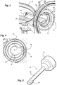
- the figure 2 presents the reduction gear housing 8 comprising along a main axis A, a first bore 22 and a second bore 24 axially spaced apart, each receiving a bearing for guiding the shaft of the reduction gear, and beyond this second bore a flange 28 supporting the electric motor 12.
- An axial bore 26 connects the two bores 22, 24 together, having a diameter slightly smaller than these bores to allow the passage of a cutting tool from a boring bar going from one to the other without unclamping the casing 8 fixed on the machine tool.
- the axial bore 26 opens onto a large circular volume 30 containing a toothed wheel linked to the steering shaft 10, receiving the movement of an endless screw disposed on the reducer shaft, between these two bearings.
- the internal diameter of the axial bore 26 is at least 27mm, allowing an axial passage of a boring bar equipped at its end with a cutting tool projecting radially, which can have any orientation around the axis principal A.
- the largest diameter of the cutting tool being a little less than 27mm, it is allowed to pass inside.
- the cylindrical outer contour 20 of the part of the casing 8 containing the axial bore 26, has a minimum diameter of approximately 33mm to obtain a sufficient material thickness of this part. In certain cases this minimum outside diameter poses problems of proximity with other components.
- the figures 3, 4 and 5 have a similar reduction gear housing 8, comprising an axial bore 26 of reduced diameter, equal to 17.4 mm, which makes it possible to include it in a cylindrical external contour 20 of this housing having a minimum diameter of approximately 23 mm, which follows the internal contour of the axial bore 26 with a single wall of interposed material.
- This cylindrical outer contour 20 comprises a reduction of the radius of about 5mm compared to that presented figure 2 .
- One side of the axial bore 26 has a longitudinal groove 40 having in a tangential direction a width equal to approximately 60% of the diameter of this bore, and in the radial direction a depth having a radius substantially equivalent to those of the bores 22, 24.
- the outer contour 20 of the casing 8 around the axial bore 26 must take into account the longitudinal groove 40 to circumvent it, however the orientation angle of this groove can be adapted to arrange it in an area where the outside space is available.
- a boring bar 50 for performing the machining of the bores 22, 24, comprises a rear portion 42 of large diameter for fixing to the machining machine, and an elongated rod 44 having at its front end a tool for section 46.
- the diameter of the axial bore 26 allows the rod 44 to be inserted into it, the cutting tool 46 passing through the longitudinal groove 40, with minimum play to avoid contact.
- the method of machining the bores 22, 24 is as follows. After machining a first bore, without unclamping the casing 8 of the machining machine, this machine automatically orients the boring bar 50 around its axis of rotation aligned with the main axis A, to adjust the cutting tool 46 on the groove 40. Then the boring bar 50 slides axially to place the cutting tool 46 at the second bore, then the factory with a radius greater than that of the bottom of this groove.
- the axial bore 26 and its groove 40 are produced economically directly by molding the casing 8 of aluminum alloy, which does not add any cost for this realization.
Landscapes
- Engineering & Computer Science (AREA)
- General Engineering & Computer Science (AREA)
- Mechanical Engineering (AREA)
- Chemical & Material Sciences (AREA)
- Combustion & Propulsion (AREA)
- Transportation (AREA)
- General Details Of Gearings (AREA)
- Power Steering Mechanism (AREA)
- Gear Transmission (AREA)
Abstract
Description
- La présente invention concerne un carter de réducteur d'un système de direction assistée de véhicule automobile, ainsi qu'un système de direction équipé d'un tel carter, et un procédé d'usinage de ce carter.
- Les véhicules automobiles comportent un volant de manœuvre entraînant une colonne de direction, reliée dans une partie inférieure à un boîtier de direction comprenant une crémaillère s'étendant suivant un axe transversal à un axe d'élongation du véhicule, réalisant un pivotement des roues avant directrices du véhicule.
- Les systèmes de direction comportent généralement un dispositif d'assistance délivrant sur la crémaillère une force dépendant de celle donnée par le conducteur, afin de diminuer l'effort demandé au conducteur.
- Un type de dispositif d'assistance électrique connu, comporte un moteur électrique relié à un réducteur comprenant une vis sans fin entraînant une roue dentée fixée sur un arbre lié à un pignon de la crémaillère, pour réaliser une forte réduction donnant un couple élevé.
- Pour obtenir une bonne précision de fonctionnement du dispositif d'assistance, le réducteur doit présenter un jeu de fonctionnement réduit. Pour cela la vis sans fin du réducteur est portée par un arbre monté sur deux roulements espacés axialement, fixés dans un même carter réalisé en alliage d'aluminium, afin d'obtenir un montage stable de cet arbre subissant des forces élevées en réaction du couple transmis.
- Les deux alésages du carter recevant chacun un roulement doivent présenter des caractéristiques géométriques précises, notamment d'alignement de ces alésages. Un procédé d'usinage connu consiste à utiliser une barre d'alésage portant à une extrémité avant un outil de coupe, qui dans une même opération d'usinage, sans retourner un plateau pivotant du carter, ni débrider le carter du plateau de la machine d'usinage, vient usiner successivement les deux alésages.
- Pour cela il est nécessaire de disposer dans le carter d'un perçage axial intermédiaire entre les deux alésages, permettant le passage de l'outil de coupe porté par la barre d'alésage pour passer de l'un à l'autre de ces alésages. On réalise l'usinage d'un premier alésage, puis sans débrider le carter de la machine, on fait coulisser axialement l'outil de coupe dans le perçage intermédiaire pour atteindre le deuxième alésage et l'usiner.
- Toutefois pour des raisons d'encombrement extérieur autour du système de direction disposé dans le compartiment moteur, recevant de plus en plus d'organes, des constructeurs cherchent à réduire l'encombrement extérieur du carter autour du perçage axial intermédiaire entre les deux alésages.
- Cet encombrement réduit donne un perçage axial intermédiaire de section réduite ne permettant plus le passage axial de l'outil de coupe, son diamètre étant inférieur au plus grand diamètre de l'outil de coupe.
- On peut alors fixer le carter sur le plateau diviseur pivotant de la machine, permettant de réaliser une division angulaire du pivotement de ce plateau, pour réaliser l'usinage d'un premier alésage disposé face à la tête d'usinage de cette machine, puis faire tourner le plateau de 180° pour retourner le carter en présentant le deuxième alésage face à cette tête afin de réaliser son usinage.
- En variante suivant le type de machine d'usinage, on peut faire pivoter le porte-outil suivant un angle de 180° pour le disposer de l'autre côté du carter, face au deuxième alésage.
- Cependant pour une production en grande série, ce procédé nécessitant un retournement du plateau diviseur ou du porte-outil, ajoute une dispersion dans l'alignement des deux alésages usinés, ce qui pose des problèmes de détérioration de la qualité de fonctionnement du réducteur.
- La présente invention a notamment pour but d'éviter ces inconvénients de la technique antérieure.
- Elle propose à cet effet un carter de réducteur d'un système de direction assistée de véhicule automobile, comprenant suivant un axe principal un premier et un deuxième alésages usinés éloignés axialement l'un de l'autre, conçus pour recevoir des roulements de guidage de l'arbre d'un réducteur d'une motorisation d'assistance, et comprenant un perçage axial intermédiaire entre ces alésages, ce carter étant remarquable en ce que le perçage intermédiaire présente une section transversale sensiblement circulaire comprenant une encoche formant sur un côté du perçage intermédiaire une rainure longitudinale qui se prolonge sur toute une longueur de ce perçage intermédiaire.
- Un avantage de ce carter est qu'en prévoyant des dimensions de la rainure longitudinale suffisantes, on permet après l'usinage d'un premier alésage avec un outil de coupe fixé sur une barre d'alésage, une avance de l'outil de coupe le long de la rainure pour atteindre la position axiale du deuxième alésage, et l'usiner. De cette manière, l'usinage successif des deux alésages est réalisé sans avoir ni à retourner un plateau du carter, ni à pivoter le porte-outil suivant un angle de 180° pour le disposer de l'autre côté du carter, face au deuxième alésage, ni à débrider le carter ou son support sur la machine d'usinage.
- On obtient de manière simple et économique un volume extérieur du carter qui est minimum, et en l'absence de débridage ou de retournement, un temps d'usinage réduit et une bonne précision d'alignement des deux alésages.
- Le carter de réducteur selon l'invention peut comporter de plus une ou plusieurs des caractéristiques suivantes, qui peuvent être combinées entre elles.
- Avantageusement, le rayon de chaque alésage est supérieur au rayon du fond de la rainure.
- Avantageusement, le carter comporte une surface extérieure ajustée autour du perçage intermédiaire, formée par une simple paroi de matière entourant ce perçage.
- Avantageusement, le perçage intermédiaire et sa rainure sont obtenus directement par un moulage de ce carter de réducteur.
- L'invention a aussi pour objet un système de direction comprenant une motorisation électrique entraînant un arbre de direction par l'intermédiaire d'un réducteur, remarquable en ce que ce réducteur comporte un carter de réducteur comprenant l'une quelconque des caractéristiques précédentes.
- En particulier, le réducteur peut être un système à roue, et vis sans fin fixée sur un arbre guidé par des roulements maintenus dans les deux alésages du carter de réducteur.
- L'invention a de plus pour objet un procédé d'usinage d'un carter de réducteur comprenant l'une quelconque des caractéristiques précédentes avec une machine d'usinage équipée d'une barre d'alésage, remarquable en ce qu'il réalise l'usinage d'un premier alésage, puis sans débrider le carter de la machine il oriente automatiquement l'outil de coupe de la barre d'alésage autour de son axe de rotation pour l'ajuster sur la rainure, puis il coulisse axialement cet outil de coupe dans la rainure pour l'ajuster sur le deuxième alésage et usiner cet alésage.
- L'invention sera mieux comprise et d'autres caractéristiques et avantages apparaîtront plus clairement à la lecture de la description ci-après donnée à titre d'exemple, en référence aux dessins annexés dans lesquels :
- la
figure 1 est une vue d'ensemble d'un système de direction ; - la
figure 2 est une vue d'un carter de réducteur selon l'art antérieur pour ce système de direction ; - la
figure 3 est une vue d'un carter de réducteur selon l'invention pour ce système de direction ; - la
figure 4 est une vue de face du perçage longitudinal de ce carter ; et - la
figure 5 est une vue d'une barre d'alésage équipée d'un outil pour l'usinage des alésages de ce carter. - La
figure 1 présente un système de direction comprenant un boîtier 2 disposé suivant axe transversal à un axe d'élongation du véhicule, fixé par des vis verticale 4 sur un berceau avant de ce véhicule, comportant une crémaillère coulissante 6 entraînée par un pignon fixé à l'extrémité inférieure d'un arbre de direction 10 commandé par un volant. - Une motorisation électrique 12 entraîne un arbre disposé dans un carter de réducteur 8 fixé sur le boîtier de direction 2, recevant aussi l'arbre de direction 10 pour le guider.
- La
figure 2 présente le carter de réducteur 8 comportant suivant un axe principal A, un premier alésage 22 et un deuxième alésage 24 axialement espacés, recevant chacun un roulement de guidage de l'arbre du réducteur, et au-delà de ce deuxième alésage une collerette 28 supportant la motorisation électrique 12. - Un perçage axial 26 relie les deux alésages 22, 24 entre eux, présentant un diamètre légèrement inférieur à ces alésages pour permettre le passage d'un outil de coupe d'une barre d'alésage allant de l'un à l'autre sans débrider le carter 8 fixé sur la machine d'usinage.
- Le perçage axial 26 débouche sur un grand volume circulaire 30 contenant une roue dentée liée à l'arbre de direction 10, recevant le mouvement d'une vis sans fin disposée sur l'arbre de réducteur, entre ces deux roulements.
- Dans cet exemple le diamètre intérieur du perçage axial 26 est de 27mm minimum, permettant un passage axial d'une barre d'alésage équipée à son extrémité d'un outil de coupe dépassant radialement, qui peut présenter une orientation quelconque autour de l'axe principal A. Le plus grand diamètre de l'outil de coupe étant un peu inférieur à 27mm, on permet son passage à l'intérieur.
- Le contour extérieur cylindrique 20 de la partie du carter 8 contenant le perçage axial 26, présente un diamètre minimum d'environ 33mm pour obtenir une épaisseur de matière suffisante de cette partie. Dans certains cas ce diamètre extérieur minimum pose des problèmes de proximité avec d'autres composants.
- Les
figures 3, 4 et 5 présentent un carter de réducteur similaire 8, comprenant un perçage axial 26 de diamètre réduit, égale à 17,4 mm, ce qui permet de l'inclure dans un contour extérieur cylindrique 20 de ce carter présentant un diamètre minimum d'environ 23mm, qui suit le contour intérieur du perçage axial 26 avec une simple paroi de matière interposée. Ce contour extérieur cylindrique 20 comporte une réduction du rayon d'environ 5mm par rapport à celui présentéfigure 2 . - Un côté du perçage axial 26 comporte une rainure longitudinale 40 présentant dans une direction tangentielle une largeur égale à environ 60% du diamètre de ce perçage, et dans la direction radiale une profondeur présentant un rayon sensiblement équivalent à ceux des alésages 22, 24.
- Le contour extérieur 20 du carter 8 autour du perçage axial 26 doit prendre en compte la rainure longitudinale 40 pour la contourner, toutefois l'orientation angulaire de cette rainure peut s'adapter pour la disposer dans une zone où l'espace extérieur est disponible.
- Une barre d'alésage 50 pour réaliser l'usinage des alésages 22, 24, comporte une partie arrière 42 de grand diamètre pour la fixation sur la machine d'usinage, et une tige allongée 44 disposant à son extrémité avant d'un outil de coupe 46.
- Comme présenté
figure 4 , le diamètre du perçage axial 26 permet d'insérer dedans la tige 44, l'outil de coupe 46 passant dans la rainure longitudinale 40, avec un jeu minimum pour éviter des contacts. - Le procédé d'usinage des alésages 22, 24 est le suivant. Après l'usinage d'un premier alésage, sans débrider le carter 8 de la machine d'usinage, cette machine oriente automatiquement la barre d'alésage 50 autour de son axe de rotation aligné sur l'axe principal A, pour ajuster l'outil de coupe 46 sur la rainure 40. Ensuite la barre d'alésage 50 coulisse axialement pour disposer l'outil de coupe 46 au niveau du deuxième alésage, puis l'usine avec un rayon supérieur à celui du fond de cette rainure.
- Avantageusement le perçage axial 26 et sa rainure 40 sont réalisés de manière économique directement par le moulage du carter 8 en alliage d'aluminium, ce qui n'ajoute pas de coût pour cette réalisation.
- On obtient avec un temps de cycle d'usinage court la meilleure précision possible pour l'alignement des alésages 22, 24, en assurant la qualité de fonctionnement du réducteur pour un coût minimum.
Claims (7)
- Carter de réducteur (8) d'un système de direction assistée de véhicule automobile, comprenant suivant un axe principal (A) un premier (22) et un deuxième (24) alésages usinés éloignés axialement l'un de l'autre, conçus pour recevoir des roulements de guidage de l'arbre d'un réducteur d'une motorisation d'assistance, et comprenant un perçage axial intermédiaire (26) entre ces alésages (22, 24), caractérisé en ce que le perçage intermédiaire (26) présente une section transversale sensiblement circulaire, comprenant une encoche formant sur un côté de ce perçage intermédiaire (26) une rainure longitudinale (40) qui se prolonge sur toute une longueur de ce perçage intermédiaire (26).
- Carter de réducteur suivant la revendication 1, caractérisé en ce que le rayon de chaque alésage (22, 24) est supérieur au rayon du fond de la rainure (40).
- Carter de réducteur suivant la revendication 1 ou 2, caractérisé en ce qu'il comporte une surface extérieure (20) ajustée autour du perçage intermédiaire (26), formée par une simple paroi de matière entourant ce perçage (26).
- Carter de réducteur selon l'une quelconque des revendications précédentes, caractérisé en ce que le perçage intermédiaire (26) et sa rainure (40) sont obtenus directement par un moulage de ce carter de réducteur (8).
- Système de direction comprenant une motorisation électrique (12) entraînant un arbre de direction (10) par l'intermédiaire d'un réducteur, caractérisé en ce que ce réducteur comporte un carter de réducteur (8) selon l'une quelconque des revendications précédentes.
- Système de direction selon la revendication 5, caractérisé en ce que le réducteur est un système à roue, et vis sans fin fixée sur un arbre guidé par des roulements maintenus dans les deux alésages (22, 24) du carter de réducteur (8).
- Procédé d'usinage d'un carter de réducteur (8) selon l'une quelconque des revendications 1 à 4, avec une machine d'usinage équipée d'une barre d'alésage (50), caractérisé en ce qu'il réalise l'usinage d'un premier alésage (22, 24), puis sans débrider le carter (8) de la machine il oriente automatiquement l'outil de coupe (46) de la barre d'alésage (50) autour de son axe de rotation pour l'ajuster sur la rainure (40), puis il coulisse axialement cet outil de coupe (46) dans la rainure pour l'ajuster sur le deuxième alésage et usiner cet alésage.
Applications Claiming Priority (1)
| Application Number | Priority Date | Filing Date | Title |
|---|---|---|---|
| FR1859219A FR3086987B1 (fr) | 2018-10-04 | 2018-10-04 | Carter de reducteur de direction assistee comprenant une encoche sur un cote d’un percage intermediaire |
Publications (2)
| Publication Number | Publication Date |
|---|---|
| EP3633236A1 true EP3633236A1 (fr) | 2020-04-08 |
| EP3633236B1 EP3633236B1 (fr) | 2021-07-14 |
Family
ID=65763533
Family Applications (1)
| Application Number | Title | Priority Date | Filing Date |
|---|---|---|---|
| EP19200676.5A Active EP3633236B1 (fr) | 2018-10-04 | 2019-10-01 | Carter de réducteur de direction assistée comprenant une encoche sur un côté d'un perçage intermédiaire |
Country Status (2)
| Country | Link |
|---|---|
| EP (1) | EP3633236B1 (fr) |
| FR (1) | FR3086987B1 (fr) |
Citations (3)
| Publication number | Priority date | Publication date | Assignee | Title |
|---|---|---|---|---|
| EP0630800A1 (fr) * | 1993-06-21 | 1994-12-28 | Valeo Electronique | Dispositif de direction assistée électrique à verrou de colonne de direction |
| US6491130B1 (en) * | 1998-12-14 | 2002-12-10 | Toyoda Koki Kabushiki Kaisha | Electric power steering apparatus |
| JP3778845B2 (ja) * | 2001-06-18 | 2006-05-24 | 株式会社ジェイテクト | 減速歯車機構及びこれを用いた電動式パワーステアリング装置 |
-
2018
- 2018-10-04 FR FR1859219A patent/FR3086987B1/fr not_active Expired - Fee Related
-
2019
- 2019-10-01 EP EP19200676.5A patent/EP3633236B1/fr active Active
Patent Citations (3)
| Publication number | Priority date | Publication date | Assignee | Title |
|---|---|---|---|---|
| EP0630800A1 (fr) * | 1993-06-21 | 1994-12-28 | Valeo Electronique | Dispositif de direction assistée électrique à verrou de colonne de direction |
| US6491130B1 (en) * | 1998-12-14 | 2002-12-10 | Toyoda Koki Kabushiki Kaisha | Electric power steering apparatus |
| JP3778845B2 (ja) * | 2001-06-18 | 2006-05-24 | 株式会社ジェイテクト | 減速歯車機構及びこれを用いた電動式パワーステアリング装置 |
Also Published As
| Publication number | Publication date |
|---|---|
| FR3086987A1 (fr) | 2020-04-10 |
| EP3633236B1 (fr) | 2021-07-14 |
| FR3086987B1 (fr) | 2021-01-01 |
Similar Documents
| Publication | Publication Date | Title |
|---|---|---|
| US7591204B2 (en) | Belt speed reducing apparatus for electric power steering apparatus and electric power steering apparatus | |
| JP5894676B2 (ja) | 車両ステアリングシステムのトランスミッション | |
| FR2853876A1 (fr) | Dispositif de direction assistee electrique | |
| EP4074452B1 (fr) | Tête de soudage par friction malaxage et procédé utilisant une telle tête de soudage | |
| EP1370388B1 (fr) | Dispositif d'entrainement et outil de serrage equipe d'un tel dispositif | |
| FR2935672A1 (fr) | Bras de suspension arriere directeur pour vehicule automobile | |
| FR2560805A1 (fr) | Robot multiple a bras horizontaux | |
| WO2021099606A1 (fr) | Fourreau de colonne de direction comportant un systeme de reglage d'une position relative entre deux tubes | |
| EP3633236B1 (fr) | Carter de réducteur de direction assistée comprenant une encoche sur un côté d'un perçage intermédiaire | |
| FR3121622A1 (fr) | Tete de prehension et de poinçonnage d’une piece permettant son entrainement en rotation pour son usinage | |
| FR2834271A1 (fr) | Ensemble structurel de planche de bord et procede pour le realiser | |
| FR2857891A1 (fr) | Tour pour portees | |
| FR3069608B1 (fr) | Systeme de commande d’un verrou de parking pour bloquer une transmission d’un vehicule automobile | |
| FR2597036A1 (fr) | Groupe moto-propulseur pour vehicule porteur de charge tel que chariot de golf et vehicule porteur de charge equipe de ce groupe moto-propulseur | |
| KR20090017923A (ko) | 백래쉬 저감장치가 구비된 유성 기어 장치 및 이를 구비한능동 전륜 조향장치 | |
| CH570840A5 (fr) | ||
| FR3034585A1 (fr) | Liaison entre un arbre de machine electrique et un reducteur | |
| FR2912195A1 (fr) | Dispositif de transmission irreversible de mouvement a engrenage, equipement electrique et vehicule automobile correspondants | |
| WO2021229175A1 (fr) | Réducteur de système à direction assistée électrique et système de direction assistée électrique | |
| FR2500395A3 (fr) | Boitier de direction pour vehicule automobile | |
| EP0299859A2 (fr) | Dispositif de commande de direction arrière pour véhicule automobile à quatre roues directrices | |
| FR2530508A1 (fr) | Barre de cremaillere metallique, procede de fabrication de cette barre de cremaillere, et engrenage de direction | |
| FR2833555A1 (fr) | Mecanisme de direction pour vehicules automobiles | |
| EP0811448A1 (fr) | Dispositif de réglage de la position d'une broche d'usinage | |
| BE438378A (fr) |
Legal Events
| Date | Code | Title | Description |
|---|---|---|---|
| PUAI | Public reference made under article 153(3) epc to a published international application that has entered the european phase |
Free format text: ORIGINAL CODE: 0009012 |
|
| STAA | Information on the status of an ep patent application or granted ep patent |
Free format text: STATUS: THE APPLICATION HAS BEEN PUBLISHED |
|
| AK | Designated contracting states |
Kind code of ref document: A1 Designated state(s): AL AT BE BG CH CY CZ DE DK EE ES FI FR GB GR HR HU IE IS IT LI LT LU LV MC MK MT NL NO PL PT RO RS SE SI SK SM TR |
|
| AX | Request for extension of the european patent |
Extension state: BA ME |
|
| STAA | Information on the status of an ep patent application or granted ep patent |
Free format text: STATUS: REQUEST FOR EXAMINATION WAS MADE |
|
| 17P | Request for examination filed |
Effective date: 20200911 |
|
| RBV | Designated contracting states (corrected) |
Designated state(s): AL AT BE BG CH CY CZ DE DK EE ES FI FR GB GR HR HU IE IS IT LI LT LU LV MC MK MT NL NO PL PT RO RS SE SI SK SM TR |
|
| RIC1 | Information provided on ipc code assigned before grant |
Ipc: F16H 57/021 20120101ALN20210204BHEP Ipc: F16H 57/02 20120101AFI20210204BHEP Ipc: B62D 5/04 20060101ALI20210204BHEP Ipc: B62D 5/00 20060101ALI20210204BHEP |
|
| GRAP | Despatch of communication of intention to grant a patent |
Free format text: ORIGINAL CODE: EPIDOSNIGR1 |
|
| STAA | Information on the status of an ep patent application or granted ep patent |
Free format text: STATUS: GRANT OF PATENT IS INTENDED |
|
| INTG | Intention to grant announced |
Effective date: 20210312 |
|
| GRAS | Grant fee paid |
Free format text: ORIGINAL CODE: EPIDOSNIGR3 |
|
| GRAA | (expected) grant |
Free format text: ORIGINAL CODE: 0009210 |
|
| STAA | Information on the status of an ep patent application or granted ep patent |
Free format text: STATUS: THE PATENT HAS BEEN GRANTED |
|
| AK | Designated contracting states |
Kind code of ref document: B1 Designated state(s): AL AT BE BG CH CY CZ DE DK EE ES FI FR GB GR HR HU IE IS IT LI LT LU LV MC MK MT NL NO PL PT RO RS SE SI SK SM TR |
|
| REG | Reference to a national code |
Ref country code: GB Ref legal event code: FG4D Free format text: NOT ENGLISH |
|
| REG | Reference to a national code |
Ref country code: DE Ref legal event code: R096 Ref document number: 602019006092 Country of ref document: DE |
|
| REG | Reference to a national code |
Ref country code: IE Ref legal event code: FG4D Free format text: LANGUAGE OF EP DOCUMENT: FRENCH |
|
| REG | Reference to a national code |
Ref country code: AT Ref legal event code: REF Ref document number: 1410909 Country of ref document: AT Kind code of ref document: T Effective date: 20210815 |
|
| PGFP | Annual fee paid to national office [announced via postgrant information from national office to epo] |
Ref country code: FR Payment date: 20210930 Year of fee payment: 3 |
|
| REG | Reference to a national code |
Ref country code: LT Ref legal event code: MG9D |
|
| REG | Reference to a national code |
Ref country code: NL Ref legal event code: MP Effective date: 20210714 |
|
| REG | Reference to a national code |
Ref country code: AT Ref legal event code: MK05 Ref document number: 1410909 Country of ref document: AT Kind code of ref document: T Effective date: 20210714 |
|
| PG25 | Lapsed in a contracting state [announced via postgrant information from national office to epo] |
Ref country code: FI Free format text: LAPSE BECAUSE OF FAILURE TO SUBMIT A TRANSLATION OF THE DESCRIPTION OR TO PAY THE FEE WITHIN THE PRESCRIBED TIME-LIMIT Effective date: 20210714 Ref country code: ES Free format text: LAPSE BECAUSE OF FAILURE TO SUBMIT A TRANSLATION OF THE DESCRIPTION OR TO PAY THE FEE WITHIN THE PRESCRIBED TIME-LIMIT Effective date: 20210714 Ref country code: SE Free format text: LAPSE BECAUSE OF FAILURE TO SUBMIT A TRANSLATION OF THE DESCRIPTION OR TO PAY THE FEE WITHIN THE PRESCRIBED TIME-LIMIT Effective date: 20210714 Ref country code: RS Free format text: LAPSE BECAUSE OF FAILURE TO SUBMIT A TRANSLATION OF THE DESCRIPTION OR TO PAY THE FEE WITHIN THE PRESCRIBED TIME-LIMIT Effective date: 20210714 Ref country code: LT Free format text: LAPSE BECAUSE OF FAILURE TO SUBMIT A TRANSLATION OF THE DESCRIPTION OR TO PAY THE FEE WITHIN THE PRESCRIBED TIME-LIMIT Effective date: 20210714 Ref country code: AT Free format text: LAPSE BECAUSE OF FAILURE TO SUBMIT A TRANSLATION OF THE DESCRIPTION OR TO PAY THE FEE WITHIN THE PRESCRIBED TIME-LIMIT Effective date: 20210714 Ref country code: BG Free format text: LAPSE BECAUSE OF FAILURE TO SUBMIT A TRANSLATION OF THE DESCRIPTION OR TO PAY THE FEE WITHIN THE PRESCRIBED TIME-LIMIT Effective date: 20211014 Ref country code: HR Free format text: LAPSE BECAUSE OF FAILURE TO SUBMIT A TRANSLATION OF THE DESCRIPTION OR TO PAY THE FEE WITHIN THE PRESCRIBED TIME-LIMIT Effective date: 20210714 Ref country code: PT Free format text: LAPSE BECAUSE OF FAILURE TO SUBMIT A TRANSLATION OF THE DESCRIPTION OR TO PAY THE FEE WITHIN THE PRESCRIBED TIME-LIMIT Effective date: 20211115 Ref country code: NL Free format text: LAPSE BECAUSE OF FAILURE TO SUBMIT A TRANSLATION OF THE DESCRIPTION OR TO PAY THE FEE WITHIN THE PRESCRIBED TIME-LIMIT Effective date: 20210714 Ref country code: NO Free format text: LAPSE BECAUSE OF FAILURE TO SUBMIT A TRANSLATION OF THE DESCRIPTION OR TO PAY THE FEE WITHIN THE PRESCRIBED TIME-LIMIT Effective date: 20211014 |
|
| PGFP | Annual fee paid to national office [announced via postgrant information from national office to epo] |
Ref country code: DE Payment date: 20210928 Year of fee payment: 3 |
|
| PG25 | Lapsed in a contracting state [announced via postgrant information from national office to epo] |
Ref country code: PL Free format text: LAPSE BECAUSE OF FAILURE TO SUBMIT A TRANSLATION OF THE DESCRIPTION OR TO PAY THE FEE WITHIN THE PRESCRIBED TIME-LIMIT Effective date: 20210714 Ref country code: LV Free format text: LAPSE BECAUSE OF FAILURE TO SUBMIT A TRANSLATION OF THE DESCRIPTION OR TO PAY THE FEE WITHIN THE PRESCRIBED TIME-LIMIT Effective date: 20210714 Ref country code: GR Free format text: LAPSE BECAUSE OF FAILURE TO SUBMIT A TRANSLATION OF THE DESCRIPTION OR TO PAY THE FEE WITHIN THE PRESCRIBED TIME-LIMIT Effective date: 20211015 |
|
| REG | Reference to a national code |
Ref country code: DE Ref legal event code: R097 Ref document number: 602019006092 Country of ref document: DE |
|
| PG25 | Lapsed in a contracting state [announced via postgrant information from national office to epo] |
Ref country code: DK Free format text: LAPSE BECAUSE OF FAILURE TO SUBMIT A TRANSLATION OF THE DESCRIPTION OR TO PAY THE FEE WITHIN THE PRESCRIBED TIME-LIMIT Effective date: 20210714 |
|
| PLBE | No opposition filed within time limit |
Free format text: ORIGINAL CODE: 0009261 |
|
| STAA | Information on the status of an ep patent application or granted ep patent |
Free format text: STATUS: NO OPPOSITION FILED WITHIN TIME LIMIT |
|
| PG25 | Lapsed in a contracting state [announced via postgrant information from national office to epo] |
Ref country code: SM Free format text: LAPSE BECAUSE OF FAILURE TO SUBMIT A TRANSLATION OF THE DESCRIPTION OR TO PAY THE FEE WITHIN THE PRESCRIBED TIME-LIMIT Effective date: 20210714 Ref country code: SK Free format text: LAPSE BECAUSE OF FAILURE TO SUBMIT A TRANSLATION OF THE DESCRIPTION OR TO PAY THE FEE WITHIN THE PRESCRIBED TIME-LIMIT Effective date: 20210714 Ref country code: RO Free format text: LAPSE BECAUSE OF FAILURE TO SUBMIT A TRANSLATION OF THE DESCRIPTION OR TO PAY THE FEE WITHIN THE PRESCRIBED TIME-LIMIT Effective date: 20210714 Ref country code: EE Free format text: LAPSE BECAUSE OF FAILURE TO SUBMIT A TRANSLATION OF THE DESCRIPTION OR TO PAY THE FEE WITHIN THE PRESCRIBED TIME-LIMIT Effective date: 20210714 Ref country code: CZ Free format text: LAPSE BECAUSE OF FAILURE TO SUBMIT A TRANSLATION OF THE DESCRIPTION OR TO PAY THE FEE WITHIN THE PRESCRIBED TIME-LIMIT Effective date: 20210714 Ref country code: AL Free format text: LAPSE BECAUSE OF FAILURE TO SUBMIT A TRANSLATION OF THE DESCRIPTION OR TO PAY THE FEE WITHIN THE PRESCRIBED TIME-LIMIT Effective date: 20210714 |
|
| 26N | No opposition filed |
Effective date: 20220419 |
|
| REG | Reference to a national code |
Ref country code: BE Ref legal event code: MM Effective date: 20211031 |
|
| PG25 | Lapsed in a contracting state [announced via postgrant information from national office to epo] |
Ref country code: MC Free format text: LAPSE BECAUSE OF FAILURE TO SUBMIT A TRANSLATION OF THE DESCRIPTION OR TO PAY THE FEE WITHIN THE PRESCRIBED TIME-LIMIT Effective date: 20210714 |
|
| PG25 | Lapsed in a contracting state [announced via postgrant information from national office to epo] |
Ref country code: LU Free format text: LAPSE BECAUSE OF NON-PAYMENT OF DUE FEES Effective date: 20211001 Ref country code: IT Free format text: LAPSE BECAUSE OF FAILURE TO SUBMIT A TRANSLATION OF THE DESCRIPTION OR TO PAY THE FEE WITHIN THE PRESCRIBED TIME-LIMIT Effective date: 20210714 Ref country code: BE Free format text: LAPSE BECAUSE OF NON-PAYMENT OF DUE FEES Effective date: 20211031 |
|
| PG25 | Lapsed in a contracting state [announced via postgrant information from national office to epo] |
Ref country code: IE Free format text: LAPSE BECAUSE OF NON-PAYMENT OF DUE FEES Effective date: 20211001 |
|
| REG | Reference to a national code |
Ref country code: DE Ref legal event code: R119 Ref document number: 602019006092 Country of ref document: DE |
|
| REG | Reference to a national code |
Ref country code: CH Ref legal event code: PL |
|
| PG25 | Lapsed in a contracting state [announced via postgrant information from national office to epo] |
Ref country code: CY Free format text: LAPSE BECAUSE OF FAILURE TO SUBMIT A TRANSLATION OF THE DESCRIPTION OR TO PAY THE FEE WITHIN THE PRESCRIBED TIME-LIMIT Effective date: 20210714 |
|
| PG25 | Lapsed in a contracting state [announced via postgrant information from national office to epo] |
Ref country code: LI Free format text: LAPSE BECAUSE OF NON-PAYMENT OF DUE FEES Effective date: 20221031 Ref country code: HU Free format text: LAPSE BECAUSE OF FAILURE TO SUBMIT A TRANSLATION OF THE DESCRIPTION OR TO PAY THE FEE WITHIN THE PRESCRIBED TIME-LIMIT; INVALID AB INITIO Effective date: 20191001 Ref country code: FR Free format text: LAPSE BECAUSE OF NON-PAYMENT OF DUE FEES Effective date: 20221031 Ref country code: DE Free format text: LAPSE BECAUSE OF NON-PAYMENT OF DUE FEES Effective date: 20230503 Ref country code: CH Free format text: LAPSE BECAUSE OF NON-PAYMENT OF DUE FEES Effective date: 20221031 |
|
| PG25 | Lapsed in a contracting state [announced via postgrant information from national office to epo] |
Ref country code: MK Free format text: LAPSE BECAUSE OF FAILURE TO SUBMIT A TRANSLATION OF THE DESCRIPTION OR TO PAY THE FEE WITHIN THE PRESCRIBED TIME-LIMIT Effective date: 20210714 |
|
| GBPC | Gb: european patent ceased through non-payment of renewal fee |
Effective date: 20231001 |
|
| PG25 | Lapsed in a contracting state [announced via postgrant information from national office to epo] |
Ref country code: TR Free format text: LAPSE BECAUSE OF FAILURE TO SUBMIT A TRANSLATION OF THE DESCRIPTION OR TO PAY THE FEE WITHIN THE PRESCRIBED TIME-LIMIT Effective date: 20210714 |
|
| PG25 | Lapsed in a contracting state [announced via postgrant information from national office to epo] |
Ref country code: GB Free format text: LAPSE BECAUSE OF NON-PAYMENT OF DUE FEES Effective date: 20231001 |
|
| PG25 | Lapsed in a contracting state [announced via postgrant information from national office to epo] |
Ref country code: GB Free format text: LAPSE BECAUSE OF NON-PAYMENT OF DUE FEES Effective date: 20231001 |
|
| PG25 | Lapsed in a contracting state [announced via postgrant information from national office to epo] |
Ref country code: MT Free format text: LAPSE BECAUSE OF FAILURE TO SUBMIT A TRANSLATION OF THE DESCRIPTION OR TO PAY THE FEE WITHIN THE PRESCRIBED TIME-LIMIT Effective date: 20210714 |