EP3633256A1 - Raccord fileté pour tuyau et procédé de production d'un raccord fileté pour tuyau - Google Patents
Raccord fileté pour tuyau et procédé de production d'un raccord fileté pour tuyau Download PDFInfo
- Publication number
- EP3633256A1 EP3633256A1 EP18806355.6A EP18806355A EP3633256A1 EP 3633256 A1 EP3633256 A1 EP 3633256A1 EP 18806355 A EP18806355 A EP 18806355A EP 3633256 A1 EP3633256 A1 EP 3633256A1
- Authority
- EP
- European Patent Office
- Prior art keywords
- plating layer
- alloy plating
- pipes
- box
- threaded connection
- Prior art date
- Legal status (The legal status is an assumption and is not a legal conclusion. Google has not performed a legal analysis and makes no representation as to the accuracy of the status listed.)
- Granted
Links
Images


Classifications
-
- F—MECHANICAL ENGINEERING; LIGHTING; HEATING; WEAPONS; BLASTING
- F16—ENGINEERING ELEMENTS AND UNITS; GENERAL MEASURES FOR PRODUCING AND MAINTAINING EFFECTIVE FUNCTIONING OF MACHINES OR INSTALLATIONS; THERMAL INSULATION IN GENERAL
- F16L—PIPES; JOINTS OR FITTINGS FOR PIPES; SUPPORTS FOR PIPES, CABLES OR PROTECTIVE TUBING; MEANS FOR THERMAL INSULATION IN GENERAL
- F16L15/00—Screw-threaded joints; Forms of screw-threads for such joints
- F16L15/08—Screw-threaded joints; Forms of screw-threads for such joints with supplementary elements
-
- C—CHEMISTRY; METALLURGY
- C10—PETROLEUM, GAS OR COKE INDUSTRIES; TECHNICAL GASES CONTAINING CARBON MONOXIDE; FUELS; LUBRICANTS; PEAT
- C10M—LUBRICATING COMPOSITIONS; USE OF CHEMICAL SUBSTANCES EITHER ALONE OR AS LUBRICATING INGREDIENTS IN A LUBRICATING COMPOSITION
- C10M107/00—Lubricating compositions characterised by the base-material being a macromolecular compound
- C10M107/38—Lubricating compositions characterised by the base-material being a macromolecular compound containing halogen
-
- C—CHEMISTRY; METALLURGY
- C10—PETROLEUM, GAS OR COKE INDUSTRIES; TECHNICAL GASES CONTAINING CARBON MONOXIDE; FUELS; LUBRICANTS; PEAT
- C10M—LUBRICATING COMPOSITIONS; USE OF CHEMICAL SUBSTANCES EITHER ALONE OR AS LUBRICATING INGREDIENTS IN A LUBRICATING COMPOSITION
- C10M145/00—Lubricating compositions characterised by the additive being a macromolecular compound containing oxygen
- C10M145/18—Macromolecular compounds obtained otherwise than by reactions only involving carbon-to-carbon unsaturated bonds
-
- C—CHEMISTRY; METALLURGY
- C10—PETROLEUM, GAS OR COKE INDUSTRIES; TECHNICAL GASES CONTAINING CARBON MONOXIDE; FUELS; LUBRICANTS; PEAT
- C10M—LUBRICATING COMPOSITIONS; USE OF CHEMICAL SUBSTANCES EITHER ALONE OR AS LUBRICATING INGREDIENTS IN A LUBRICATING COMPOSITION
- C10M147/00—Lubricating compositions characterised by the additive being a macromolecular compound containing halogen
- C10M147/02—Monomer containing carbon, hydrogen and halogen only
-
- C—CHEMISTRY; METALLURGY
- C10—PETROLEUM, GAS OR COKE INDUSTRIES; TECHNICAL GASES CONTAINING CARBON MONOXIDE; FUELS; LUBRICANTS; PEAT
- C10M—LUBRICATING COMPOSITIONS; USE OF CHEMICAL SUBSTANCES EITHER ALONE OR AS LUBRICATING INGREDIENTS IN A LUBRICATING COMPOSITION
- C10M147/00—Lubricating compositions characterised by the additive being a macromolecular compound containing halogen
- C10M147/04—Monomer containing carbon, hydrogen, halogen and oxygen
-
- C—CHEMISTRY; METALLURGY
- C10—PETROLEUM, GAS OR COKE INDUSTRIES; TECHNICAL GASES CONTAINING CARBON MONOXIDE; FUELS; LUBRICANTS; PEAT
- C10M—LUBRICATING COMPOSITIONS; USE OF CHEMICAL SUBSTANCES EITHER ALONE OR AS LUBRICATING INGREDIENTS IN A LUBRICATING COMPOSITION
- C10M149/00—Lubricating compositions characterised by the additive being a macromolecular compound containing nitrogen
- C10M149/12—Macromolecular compounds obtained otherwise than by reactions only involving carbon-to-carbon unsaturated bonds
- C10M149/14—Macromolecular compounds obtained otherwise than by reactions only involving carbon-to-carbon unsaturated bonds a condensation reaction being involved
- C10M149/16—Macromolecular compounds obtained otherwise than by reactions only involving carbon-to-carbon unsaturated bonds a condensation reaction being involved between the nitrogen-containing monomer and an aldehyde or ketone
-
- C—CHEMISTRY; METALLURGY
- C10—PETROLEUM, GAS OR COKE INDUSTRIES; TECHNICAL GASES CONTAINING CARBON MONOXIDE; FUELS; LUBRICANTS; PEAT
- C10M—LUBRICATING COMPOSITIONS; USE OF CHEMICAL SUBSTANCES EITHER ALONE OR AS LUBRICATING INGREDIENTS IN A LUBRICATING COMPOSITION
- C10M149/00—Lubricating compositions characterised by the additive being a macromolecular compound containing nitrogen
- C10M149/12—Macromolecular compounds obtained otherwise than by reactions only involving carbon-to-carbon unsaturated bonds
- C10M149/14—Macromolecular compounds obtained otherwise than by reactions only involving carbon-to-carbon unsaturated bonds a condensation reaction being involved
- C10M149/18—Polyamides
-
- C—CHEMISTRY; METALLURGY
- C23—COATING METALLIC MATERIAL; COATING MATERIAL WITH METALLIC MATERIAL; CHEMICAL SURFACE TREATMENT; DIFFUSION TREATMENT OF METALLIC MATERIAL; COATING BY VACUUM EVAPORATION, BY SPUTTERING, BY ION IMPLANTATION OR BY CHEMICAL VAPOUR DEPOSITION, IN GENERAL; INHIBITING CORROSION OF METALLIC MATERIAL OR INCRUSTATION IN GENERAL
- C23C—COATING METALLIC MATERIAL; COATING MATERIAL WITH METALLIC MATERIAL; SURFACE TREATMENT OF METALLIC MATERIAL BY DIFFUSION INTO THE SURFACE, BY CHEMICAL CONVERSION OR SUBSTITUTION; COATING BY VACUUM EVAPORATION, BY SPUTTERING, BY ION IMPLANTATION OR BY CHEMICAL VAPOUR DEPOSITION, IN GENERAL
- C23C28/00—Coating for obtaining at least two superposed coatings either by methods not provided for in a single one of groups C23C2/00 - C23C26/00 or by combinations of methods provided for in subclasses C23C and C25C or C25D
-
- C—CHEMISTRY; METALLURGY
- C25—ELECTROLYTIC OR ELECTROPHORETIC PROCESSES; APPARATUS THEREFOR
- C25D—PROCESSES FOR THE ELECTROLYTIC OR ELECTROPHORETIC PRODUCTION OF COATINGS; ELECTROFORMING; APPARATUS THEREFOR
- C25D5/00—Electroplating characterised by the process; Pretreatment or after-treatment of workpieces
- C25D5/10—Electroplating with more than one layer of the same or of different metals
- C25D5/12—Electroplating with more than one layer of the same or of different metals at least one layer being of nickel or chromium
-
- C—CHEMISTRY; METALLURGY
- C25—ELECTROLYTIC OR ELECTROPHORETIC PROCESSES; APPARATUS THEREFOR
- C25D—PROCESSES FOR THE ELECTROLYTIC OR ELECTROPHORETIC PRODUCTION OF COATINGS; ELECTROFORMING; APPARATUS THEREFOR
- C25D5/00—Electroplating characterised by the process; Pretreatment or after-treatment of workpieces
- C25D5/34—Pretreatment of metallic surfaces to be electroplated
- C25D5/36—Pretreatment of metallic surfaces to be electroplated of iron or steel
-
- C—CHEMISTRY; METALLURGY
- C25—ELECTROLYTIC OR ELECTROPHORETIC PROCESSES; APPARATUS THEREFOR
- C25D—PROCESSES FOR THE ELECTROLYTIC OR ELECTROPHORETIC PRODUCTION OF COATINGS; ELECTROFORMING; APPARATUS THEREFOR
- C25D7/00—Electroplating characterised by the article coated
- C25D7/04—Tubes; Rings; Hollow bodies
-
- E—FIXED CONSTRUCTIONS
- E21—EARTH OR ROCK DRILLING; MINING
- E21B—EARTH OR ROCK DRILLING; OBTAINING OIL, GAS, WATER, SOLUBLE OR MELTABLE MATERIALS OR A SLURRY OF MINERALS FROM WELLS
- E21B17/00—Drilling rods or pipes; Flexible drill strings; Kellies; Drill collars; Sucker rods; Cables; Casings; Tubings
- E21B17/02—Couplings; joints
- E21B17/04—Couplings; joints between rod or the like and bit or between rod and rod or the like
- E21B17/042—Threaded
-
- F—MECHANICAL ENGINEERING; LIGHTING; HEATING; WEAPONS; BLASTING
- F16—ENGINEERING ELEMENTS AND UNITS; GENERAL MEASURES FOR PRODUCING AND MAINTAINING EFFECTIVE FUNCTIONING OF MACHINES OR INSTALLATIONS; THERMAL INSULATION IN GENERAL
- F16L—PIPES; JOINTS OR FITTINGS FOR PIPES; SUPPORTS FOR PIPES, CABLES OR PROTECTIVE TUBING; MEANS FOR THERMAL INSULATION IN GENERAL
- F16L15/00—Screw-threaded joints; Forms of screw-threads for such joints
-
- F—MECHANICAL ENGINEERING; LIGHTING; HEATING; WEAPONS; BLASTING
- F16—ENGINEERING ELEMENTS AND UNITS; GENERAL MEASURES FOR PRODUCING AND MAINTAINING EFFECTIVE FUNCTIONING OF MACHINES OR INSTALLATIONS; THERMAL INSULATION IN GENERAL
- F16L—PIPES; JOINTS OR FITTINGS FOR PIPES; SUPPORTS FOR PIPES, CABLES OR PROTECTIVE TUBING; MEANS FOR THERMAL INSULATION IN GENERAL
- F16L58/00—Protection of pipes or pipe fittings against corrosion or incrustation
- F16L58/02—Protection of pipes or pipe fittings against corrosion or incrustation by means of internal or external coatings
- F16L58/04—Coatings characterised by the materials used
- F16L58/08—Coatings characterised by the materials used by metal
-
- F—MECHANICAL ENGINEERING; LIGHTING; HEATING; WEAPONS; BLASTING
- F16—ENGINEERING ELEMENTS AND UNITS; GENERAL MEASURES FOR PRODUCING AND MAINTAINING EFFECTIVE FUNCTIONING OF MACHINES OR INSTALLATIONS; THERMAL INSULATION IN GENERAL
- F16L—PIPES; JOINTS OR FITTINGS FOR PIPES; SUPPORTS FOR PIPES, CABLES OR PROTECTIVE TUBING; MEANS FOR THERMAL INSULATION IN GENERAL
- F16L58/00—Protection of pipes or pipe fittings against corrosion or incrustation
- F16L58/02—Protection of pipes or pipe fittings against corrosion or incrustation by means of internal or external coatings
- F16L58/04—Coatings characterised by the materials used
- F16L58/10—Coatings characterised by the materials used by rubber or plastics
- F16L58/1054—Coatings characterised by the materials used by rubber or plastics the coating being placed outside the pipe
-
- F—MECHANICAL ENGINEERING; LIGHTING; HEATING; WEAPONS; BLASTING
- F16—ENGINEERING ELEMENTS AND UNITS; GENERAL MEASURES FOR PRODUCING AND MAINTAINING EFFECTIVE FUNCTIONING OF MACHINES OR INSTALLATIONS; THERMAL INSULATION IN GENERAL
- F16L—PIPES; JOINTS OR FITTINGS FOR PIPES; SUPPORTS FOR PIPES, CABLES OR PROTECTIVE TUBING; MEANS FOR THERMAL INSULATION IN GENERAL
- F16L58/00—Protection of pipes or pipe fittings against corrosion or incrustation
- F16L58/18—Protection of pipes or pipe fittings against corrosion or incrustation specially adapted for pipe fittings
- F16L58/182—Protection of pipes or pipe fittings against corrosion or incrustation specially adapted for pipe fittings for screw-threaded joints
-
- F—MECHANICAL ENGINEERING; LIGHTING; HEATING; WEAPONS; BLASTING
- F16—ENGINEERING ELEMENTS AND UNITS; GENERAL MEASURES FOR PRODUCING AND MAINTAINING EFFECTIVE FUNCTIONING OF MACHINES OR INSTALLATIONS; THERMAL INSULATION IN GENERAL
- F16L—PIPES; JOINTS OR FITTINGS FOR PIPES; SUPPORTS FOR PIPES, CABLES OR PROTECTIVE TUBING; MEANS FOR THERMAL INSULATION IN GENERAL
- F16L15/00—Screw-threaded joints; Forms of screw-threads for such joints
- F16L15/001—Screw-threaded joints; Forms of screw-threads for such joints with conical threads
- F16L15/004—Screw-threaded joints; Forms of screw-threads for such joints with conical threads with axial sealings having at least one plastically deformable sealing surface
-
- F—MECHANICAL ENGINEERING; LIGHTING; HEATING; WEAPONS; BLASTING
- F16—ENGINEERING ELEMENTS AND UNITS; GENERAL MEASURES FOR PRODUCING AND MAINTAINING EFFECTIVE FUNCTIONING OF MACHINES OR INSTALLATIONS; THERMAL INSULATION IN GENERAL
- F16L—PIPES; JOINTS OR FITTINGS FOR PIPES; SUPPORTS FOR PIPES, CABLES OR PROTECTIVE TUBING; MEANS FOR THERMAL INSULATION IN GENERAL
- F16L15/00—Screw-threaded joints; Forms of screw-threads for such joints
- F16L15/006—Screw-threaded joints; Forms of screw-threads for such joints with straight threads
- F16L15/009—Screw-threaded joints; Forms of screw-threads for such joints with straight threads with axial sealings having at least one plastically deformable sealing surface
Definitions
- the present invention relates to a threaded connection for pipes or tubes and a method for producing the threaded connection for pipes or tubes, and more particularly to a threaded connection for oil country tubular goods and a method for producing the threaded connection for oil country tubular goods.
- Oil well pipes are used for drilling of oil fields and natural gas fields.
- Oil well pipes are formed by coupling a plurality of steel pipes in accordance with the depth of the well. Connection of steel pipes can be carried out by fastening threaded connection for pipes or tubes formed at ends of the two steel pipes. Oil well pipes are lifted and loosened for inspection and the like, and then refastened after being inspected, and reused.
- Threaded connection for pipes or tubes include a pin and a box.
- the pin includes a male threaded portion and an unthreaded metal contact portion formed in the outer peripheral surface at the end of the pipe.
- the box includes a female threaded portion and an unthreaded metal contact portion formed in the inner peripheral surface at the end of the pipe.
- heavy metal-containing compound greases referred to as dopes
- dopes have been used to improve the galling resistance.
- Application of a compound grease to the surface of a threaded connection for pipes or tubes can improve the galling resistance of the threaded connection for pipes or tubes.
- heavy metals contained in compound greases such as Pb, Zn, and Cu, may affect the environment. For this reason, practical application of a compound grease-free threaded connection for pipes or tubes is desired.
- Patent Literature 1 Japanese Patent Application Publication No. 2002-221288 (Patent Literature 1) and Japanese Patent Application Publication No. 2008-215473 (Patent Literature 2) propose a threaded connection for pipes or tubes that does not include a compound grease but has excellent galling resistance.
- a porous Zn or Zn alloy layer is formed by an impact plating method on at least one of a threaded portion or an unthreaded metal contact portion of the threaded connection for pipes or tubes, and a solid lubricant coating layer or a liquid lubricant coating that does not contain heavy metal powder (for example, a coating having an overbased organic metal salt such as overbased sulfonate as a main component) is formed thereon.
- Patent Literature 1 describes that, by this means, a threaded connection for pipes or tubes having high anticorrosive properties is provided that, without using a liquid lubricant containing heavy metal powder such as compound grease, can suppress the occurrence of galling as well as a decline in gas tightness caused by rust occurrence when tightening and loosening are repeatedly performed.
- a threaded connection for pipes or tubes described in Patent Literature 2 is characterized by having a first plating layer composed on a Cu-Zn alloy on at least one of the contact surfaces of a pin and a box.
- Patent Literature 2 describes that, as a result, a threaded connection has excellent leakage resistance and galling resistance, and furthermore, crevice corrosion in a case where a lubricant coating is formed on the plating layer is improved.
- the aforementioned unthreaded metal contact portions include metal seal portions and shoulder portions.
- shouldering torque Torque that arises at that time.
- fastening is continued until fastening is completed.
- yield torque The torque at such time.
- fastening torque The torque when fastening is completed (hereunder, referred to as “fastening torque") is set so that a sufficient seal interfacial pressure is obtained irrespective of the size of the thread interference amount. If there is a sufficient difference between the shouldering torque and the yield torque (hereunder, this difference is referred to as “torque on shoulder resistance ⁇ T'''), the range of the fastening torque widens. As a result, the fastening torque is adjusted easily. Therefore, it is necessary that, in addition to the aforementioned misalignment resistance, a threaded connection for pipes or tubes also has a high torque on shoulder resistance ⁇ T'.
- oil country tubular goods after production, are transported by ship or by other means and stored for a certain period of time before being used. In some cases, the transport and storage of oil country tubular goods extend for a long time. Furthermore, in some cases, oil country tubular goods are stored in an outdoor location. When oil country tubular goods are stored in an outdoor location for a long period of time, the threaded connections for pipes or tubes may be subjected to corrosion, which can result in decreased galling resistance and gas tightness of the threaded connections for pipes or tubes. Therefore, it is necessary that threaded connections for pipes or tubes have not only the aforementioned misalignment resistance and high torque on shoulder resistance ⁇ T', but also excellent corrosion resistance properties.
- the Zn or Zn alloy layer is porous. Therefore, the adhesion properties with respect to the solid lubricant coating layer are good, and the threaded connection for pipes or tubes has sufficient galling resistance.
- the Zn or Zn alloy layer is porous, an air gap arises between the Zn or Zn alloy layer and the base material. Consequently, in some cases the base material at the air gap portion that arises corrodes over the course of a long period.
- Patent Literature 2 although the galling resistance of the disclosed threaded connection for pipes or tubes is investigated therein, the misalignment resistance of the threaded connection for pipes or tubes is not investigated therein. Therefore, even if the galling resistance is sufficient in a case where misalignment does not arise, the misalignment resistance may be low. In addition, in some cases the torque on shoulder resistance ⁇ T' decreases, and the adhesion properties of the solid lubricant coating layer are low and the corrosion resistance properties are low.
- An objective of the present invention is to provide a threaded connection for pipes or tubes having excellent misalignment resistance and high torque on shoulder resistance ⁇ T', and also having excellent corrosion resistance properties, as well as a method for producing the threaded connection for pipes or tubes.
- the threaded connection for pipes or tubes includes a pin and a box.
- the pin and the box each include a contact surface that includes a threaded portion and an unthreaded metal contact portion. At least one of the contact surfaces of the pin and the box has a surface roughness having an arithmetic mean roughness Ra of 1 to 8 ⁇ m and a maximum height roughness Rz of 10 to 40 ⁇ m.
- the threaded connection for pipes or tubes includes, on a contact surface having the aforementioned surface roughness, a Zn-Ni alloy plating layer consisting of a Zn-Ni alloy, a Cu-Sn-Zn alloy plating layer consisting of a Cu-Sn-Zn alloy, and a solid lubricant coating layer.
- the solid lubricant coating layer contains fluororesin particles and at least one type of resin selected from the group consisting of epoxy resin and polyamide-imide resin.
- the arithmetic mean roughness Ra and the maximum height roughness Rz are measured based on JIS B 0601 (2013).
- the method for producing a threaded connection for pipes or tubes of the present embodiment is a method for producing a threaded connection for pipes or tubes that includes a pin and a box.
- the pin and the box each include a contact surface having a threaded portion and an unthreaded metal contact portion.
- the production method of the present embodiment includes a surface roughness formation step, a Zn-Ni alloy plating layer formation step, a Cu-Sn-Zn alloy plating layer formation step and a solid lubricant coating layer formation step.
- a surface roughness having an arithmetic mean roughness Ra of 1 to 8 ⁇ m and a maximum height roughness Rz of 10 to 40 ⁇ m is formed on at least one of the contact surfaces of the pin and the box by a blasting process.
- a Zn-Ni alloy plating layer consisting of a Zn-Ni alloy is formed by electroplating on the contact surface on which the aforementioned surface roughness was formed.
- a Cu-Sn-Zn alloy plating layer consisting of a Cu-Sn-Zn alloy is formed by electroplating after the Zn-Ni alloy plating layer is formed.
- a solid lubricant coating layer formation step a solid lubricant coating layer is formed after the Cu-Sn-Zn alloy plating layer is formed.
- the threaded connection for pipes or tubes of the present embodiment is excellent in misalignment resistance, has a high torque on shoulder resistance ⁇ T', and has excellent corrosion resistance properties.
- the present inventor conducted various studies regarding the relation between a threaded connection for pipes or tubes, misalignment resistance, the torque on shoulder resistance ⁇ T', and corrosion resistance properties. As a result, the present inventor obtained the following findings.
- misalignment refers to a situation that is illustrated in FIG. 1 .
- a coupling 2 is attached to a tip end of a steel pipe 1.
- a pin 3 is formed at the other tip end of the steel pipe 1.
- a coupling 5 is attached to a tip end of a different steel pipe 4.
- a box is formed on the inner peripheral surface of the coupling 5. The pin 3 of the steel pipe 1 is inserted into the coupling 5 and fastened. By this means, the steel pipe 1 is connected to the steel pipe 4.
- misalignment When fastening is performed, in some cases the central axis in the longitudinal direction of the steel pipe 1 and the central axis in the longitudinal direction of the steel pipe 4 are out of alignment and intersect with each other. Such a situation is referred to as a "misalignment".
- FIG. 1 a misalignment in which the toe angle is ⁇ ° is illustrated. If fastening is performed in a state in which a misalignment has occurred, galling is more likely to occur in comparison to a situation in which there is no misalignment.
- the Zn-Ni alloy plating layer, the Cu-Sn-Zn alloy plating layer and the solid lubricant coating layer are generically referred to as simply "coating".
- coating In order to increase the misalignment resistance of the threaded connection for pipes or tubes, the adhesion properties of the coating are enhanced.
- Surface roughness having an arithmetic mean roughness Ra of 1 to 8 ⁇ m and a maximum height roughness Rz of 10 to 40 ⁇ m (hereinafter, also referred to as "specific surface roughness”) is formed on the threaded portion and unthreaded metal contact portion (hereinafter, referred to as "contact surface”) of at least one of the pin and the box.
- the adhesion properties are improved by a so-called “anchor effect".
- the adhesion properties of the coating are improved, delamination of the coating is suppressed, even in a case where the threaded connection for pipes or tubes is repeatedly exposed to a high temperature and a low temperature. If delamination of the coating is suppressed, high lubricity is maintained during fastening and loosening. Therefore, the misalignment resistance of the threaded connection for pipes or tubes increases.
- a plating layer having high hardness and a high fusing point is additionally formed on the contact surface. If the hardness of the plating layer is high, the plating layer is not liable to be damaged easily when fastening and loosening the threaded connection for pipes or tubes. In addition, if the fusing point of the plating layer is high, when fastening and loosening the threaded connection for pipes or tubes, it is difficult for elution of the plating layer to occur even in a case where a high temperature arises locally in the plating layer.
- a Cu-Sn-Zn alloy has high hardness and a high fusing point. Therefore, the present embodiment includes a Cu-Sn-Zn alloy plating layer consisting of a Cu-Sn-Zn alloy. Consequently, the misalignment resistance of the threaded connection for pipes or tubes increases further.
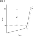
- FIG. 2 is a graph illustrating the relation between the number of turns of steel pipes and the torque during fastening of threaded connections for pipes or tubes that have a shoulder portion.
- fastening of the threaded connections for pipes or tubes initially increases the torque in proportion to the number of turns. The rate of increase in the torque at such time is low.
- shouldering torque The torque at such time is referred to as "shouldering torque”. After the shouldering torque is reached, when fastening is continued, the torque again increases in proportion to the number of turns. The rate of increase in the torque at such time is high.
- the fastening is completed at a time point at which the torque reaches a predetermined numerical value (fastening torque). If the torque during fastening reaches the fastening torque, the metal seal portions interfere with each other with an appropriate interfacial pressure. In this case, the gas tightness of the threaded connections for pipes or tubes increases.
- the torque becomes too high. If the torque becomes too high, a part of the pin and the box undergoes a plastic deformation.
- the torque at such time is referred to as "yield torque".
- yield torque When the torque on shoulder resistance ⁇ T' which is the difference between the shouldering torque and the yield torque is large, a margin can be provided with respect to the range of the fastening torque. As a result, it is easy to adjust the fastening torque. Therefore, a higher value for the torque on shoulder resistance ⁇ T' is preferable.
- the frictional resistance is reduced in order to reduce the shouldering torque.
- the lubricity of the solid lubricant coating layer is increased in order to reduce the frictional resistance. If the solid lubricant coating layer contains fluororesin particles and at least one type of resin selected from the group consisting of epoxy resin and polyamide-imide resin, the lubricity increases. In this case, the shouldering torque can be maintained at a low amount.
- Zinc (Zn) is a base metal in comparison to iron (Fe), nickel (Ni) and chromium (Cr). Therefore, by forming a plating layer containing zinc (Zn) on the contact surface, the plating layer is corroded with priority relative to the steel material (sacrificial protection). By this means, the threaded connection for pipes or tubes exhibits improved corrosion resistance properties.
- the order of depositing the Zn-Ni alloy plating layer, the Cu-Sn-Zn alloy plating layer and the solid lubricant coating layer is important.
- the order of depositing the Zn-Ni alloy plating layer and the Cu-Sn-Zn alloy plating layer is important. Table 1 shown hereunder was obtained by extracting some of the data obtained in examples that are described later.
- Test No. 1 and Test No. 8 all the conditions were the same except for the order of depositing the plating layers on the box surface.
- the surface roughness before plating was the same. Specifically, the arithmetic mean roughness Ra of the pin surface was 0.3 ⁇ m, and the maximum height roughness Rz of the pin surface was 5.8 ⁇ m.
- the arithmetic mean roughness Ra of the box surface was 2.0 ⁇ m, and the maximum height roughness Rz of the box surface was 24.0 ⁇ m.
- a chromate coating was formed on the Zn-Ni alloy plating layer on the pin surface.
- a solid lubricant coating layer containing 10% polytetrafluoroethylene particles and epoxy resin was formed on the outermost layer of the box surface.
- the threaded connection for pipes or tubes of Test No. 8 included a Zn-Ni alloy plating layer, a Cu-Sn-Zn alloy plating layer and a solid lubricant coating layer.
- the threaded connection for pipes or tubes of Test No. 8 included the Zn-Ni alloy plating layer on the Cu-Sn-Zn alloy plating layer.
- the galling resistance of the threaded connection for pipes or tubes of Test No. 8 was 5 times in the galling resistance evaluation with hand tightening, and was 5 times in the evaluation of the misalignment resistance evaluation test.
- the galling resistance of the threaded connection for pipes or tubes of Test No. 1 in which a Cu-Sn-Zn alloy plating layer was formed on a Zn-Ni alloy plating layer was more than 20 times in the galling resistance evaluation with hand tightening, and was more than 20 times in the evaluation of the misalignment resistance evaluation test.
- rust did not occur on the box of the threaded connection for pipes or tubes of Test No. 1 for 4000 hours of salt spraying.
- the Zn-Ni alloy plating layer improves the corrosion resistance properties of the threaded connection for pipes or tubes by sacrificial protection. If the Zn-Ni alloy plating layer is away from the base material of the threaded connection for pipes or tubes, the sacrificial protection effect decreases. Therefore, the corrosion resistance properties of the threaded connection for pipes or tubes decrease.
- the Cu-Sn-Zn alloy plating layer has high hardness and a high fusing point.
- the Cu-Sn-Zn alloy plating layer protects the Zn-Ni alloy plating layer that is below the Cu-Sn-Zn alloy plating layer from damage. This effect is not obtained when the Cu-Sn-Zn alloy plating layer is below the Zn-Ni alloy plating layer. Therefore, on the contact surface, it is important to deposit the Zn-Ni alloy plating layer and the Cu-Sn-Zn alloy plating layer in that order from the contact surface side.
- the threaded connection for pipes or tubes of the present embodiment that was completed based on the above findings includes a pin and a box.
- the pin and the box each include a contact surface having a threaded portion and an unthreaded metal contact portion. At least one of the contact surfaces of the pin and box has a surface roughness having an arithmetic mean roughness Ra of 1 to 8 ⁇ m and a maximum height roughness Rz of 10 to 40 ⁇ m.
- the threaded connection for pipes or tubes includes, on a contact surface having the aforementioned surface roughness, a Zn-Ni alloy plating layer consisting of a Zn-Ni alloy, a Cu-Sn-Zn alloy plating layer consisting of a Cu-Sn-Zn alloy, and a solid lubricant coating layer. These layers are deposited in the order of the Zn-Ni alloy plating layer, the Cu-Sn-Zn alloy plating layer and the solid lubricant coating layer from the contact surface side.
- the solid lubricant coating layer contains fluororesin particles and at least one type of resin selected from the group consisting of epoxy resin and polyamide-imide resin.
- the threaded connection for pipes or tubes of the present embodiment is excellent in misalignment resistance, has a high torque on shoulder resistance ⁇ T', and has excellent corrosion resistance properties.
- the hardness of the Zn-Ni alloy plating layer is a micro-Vickers hardness of 300 or more, and the thickness of the Zn-Ni alloy plating layer is in a range of 5 to 20 ⁇ m.
- the hardness of the Cu-Sn-Zn alloy plating layer is a micro-Vickers hardness of 500 or more, and the thickness of the Cu-Sn-Zn alloy plating layer is in a range of 5 to 20 ⁇ m.
- the misalignment resistance is further improved.
- the hardness of the solid lubricant coating layer is a micro-Vickers hardness in a range of 15 to 25, and the thickness of the solid lubricant coating layer is in a range of 10 to 40 ⁇ m.
- the fluororesin particles are one or more types selected from the group consisting of polytetrafluoroethylene, tetrafluoroethylene-perfluoroalkylvinyl ether copolymer, tetrafluoroethylene-hexafluoropropylene copolymer (4.6 fluoride), tetrafluoroethylene-ethylene copolymer, polyvinylidene difluoride (2 fluoride), and polychlorotrifluoro-ethylene (3 fluoride).
- the method for producing a threaded connection for pipes or tubes of the present embodiment is a method for producing a threaded connection for pipes or tubes that includes a pin and a box.
- the pin and the box each include a contact surface having a threaded portion and an unthreaded metal contact portion.
- the production method of the present embodiment includes a surface roughness formation step, a Zn-Ni alloy plating layer formation step, a Cu-Sn-Zn alloy plating layer formation step and a solid lubricant coating layer formation step.
- a surface roughness having an arithmetic mean roughness Ra of 1 to 8 ⁇ m and a maximum height roughness Rz of 10 to 40 ⁇ m is formed on at least one of the contact surfaces of the pin and the box by a blasting process.
- a Zn-Ni alloy plating layer consisting of a Zn-Ni alloy is formed by electroplating on the contact surface on which the aforementioned surface roughness was formed.
- a Cu-Sn-Zn alloy plating layer consisting of a Cu-Sn-Zn alloy is formed by electroplating after the Zn-Ni alloy plating layer is formed.
- a solid lubricant coating layer formation step a solid lubricant coating layer is formed after the Cu-Sn-Zn alloy plating layer is formed.
- a threaded connection for pipes or tubes having a specific surface roughness, a Zn-Ni alloy plating layer, a Cu-Sn-Zn alloy plating layer and a solid lubricant coating layer on at least one of the contact surfaces of a pin and a box can be produced by the production method of the present embodiment.
- the threaded connection for pipes or tubes is excellent in misalignment resistance and corrosion resistance properties.
- the threaded connection for pipes or tubes also has a high torque on shoulder resistance ⁇ T', adjustment of fastening torque is easy.
- the threaded connection for pipes or tubes includes a pin and a box.
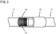
- FIG. 3 is a diagram illustrating a configuration of the threaded connection for pipes or tubes according to the present embodiment.
- the threaded connection for pipes or tubes includes a steel pipe 11 and a coupling 12.
- a pin 13 is formed at each end of the steel pipe 11, and the pin 13 includes a male threaded portion in its outer surface.
- a box 14 is formed at each end of the coupling 12, and the box 14 includes a female threaded portion in its inner surface.
- the coupling 12 is attached to the end of the steel pipe 11 by fastening the pin 13 and the box 14 together.
- integral-type threaded connections for pipes or tubes are also available in which the coupling 12 is not used, and one of the ends of the steel pipe 11 is used as the pin 13, and the other end of the steel pipe 11 is used as the box 14.
- the threaded connection for pipes or tubes of the present embodiment can be used for both a coupling-type and an integral-type threaded connection for pipes or tubes.
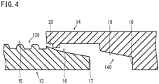
- FIG. 4 is a cross-sectional view of the threaded connection for pipes or tubes according to the present embodiment.
- the pin 13 includes a male threaded portion 15 and an unthreaded metal contact portion.
- the box 14 includes a female threaded portion 20 and an unthreaded metal contact portion.
- the unthreaded metal contact portion is formed at the tip end of the pin 13 and the box 14, and includes metal seal portions 16 and 19 and shoulder portions 17 and 18.
- the portions at which the pin 13 and the box 14 come into contact with each other when they are fastened together are referred to as contact surfaces 130 and 140.
- the two shoulder portions (shoulder portions 17 and 18) come into contact with each other, and so do the two metal seal portions (metal seal portions 16 and 19) and the two threaded portions (male threaded portion 15 and female threaded portion 20). That is, the contact surface 130 on the pin side includes the shoulder portion 17, the metal seal portion 16 and the male threaded portion 15.
- the contact surface 140 on the box side includes the shoulder portion 18, the metal seal portion 19 and the female threaded portion 20.
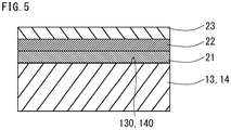
- FIG. 5 is a cross-sectional view of the contact surfaces 130 and 140 of the threaded connection for pipes or tubes according to the present embodiment.
- the threaded connection for pipes or tubes has an unshown specific surface roughness on at least one of the contact surfaces 130 and 140 of the pin 13 and the box 14.
- the threaded connection for pipes or tubes includes a Zn-Ni alloy plating layer 21, a Cu-Sn-Zn alloy plating layer 22 and a solid lubricant coating layer 23 on the contact surface 130 or 140 having the specific surface roughness. These layers are deposited in the order of the Zn-Ni alloy plating layer 21, the Cu-Sn-Zn alloy plating layer 22 and the solid lubricant coating layer 23 from the relevant contact surface 130 or 140 side.
- a surface roughness (specific surface roughness) having an arithmetic mean roughness Ra of 1 to 8 ⁇ m and a maximum height roughness Rz of 10 to 40 ⁇ m is formed on at least one of the contact surfaces 130 and 140 of the pin 13 and the box 14.
- the specific surface roughness is formed by a blasting process.
- the relevant contact surface 130 or 140 has unevenness. Therefore, the adhesion properties of the Zn-Ni alloy plating layer 21 that is described later increase because of an anchor effect.
- the adhesion properties of the Zn-Ni alloy plating layer 21 increase, the threaded connection for pipes or tubes exhibits increased misalignment resistance.
- the arithmetic mean roughness Ra is less than 1 ⁇ m and the maximum height roughness Rz is less than 10 ⁇ m, an adequate anchor effect is not obtained.
- the arithmetic mean roughness Ra is more than 8 ⁇ m and in a case where the maximum height roughness Rz is more than 40 ⁇ m, the galling resistance or the gas tightness may decrease.
- a lower limit of the arithmetic mean roughness Ra is preferably 1.5 ⁇ m, and more preferably is 2 ⁇ m.
- An upper limit of the arithmetic mean roughness Ra is preferably 7 ⁇ m, and more preferably is 5 ⁇ m.
- a lower limit of the maximum height roughness Rz is preferably 12 ⁇ m, and more preferably is 15 ⁇ m.
- An upper limit of the maximum height roughness Rz is preferably 35 ⁇ m, and more preferably is 30 ⁇ m.
- the arithmetic mean roughness Ra and the maximum height roughness Rz referred to in the present description are measured based on JIS B 0601 (2013).
- the maximum height roughness Rz and the arithmetic mean roughness Ra are measured using a scanning probe microscope (SPI 3800N, manufactured by SII NanoTechnology Inc.).
- the measurement conditions are the number of acquired data points of 1024 ⁇ 1024 in sample regions of 2 ⁇ m ⁇ 2 ⁇ m as a unit of acquired data.
- the sampling length is 2.5 mm.
- the adhesion properties with respect to the Zn-Ni alloy plating layer 21 increase by an anchor effect.
- the adhesion properties of the Zn-Ni alloy plating layer 21 increase, the threaded connection for pipes or tubes exhibits increased misalignment resistance.
- the blasting process may be performed by a well-known method in conformity with JIS Z 0310 (2016).
- such methods include sandblasting, shotblasting and grit blasting.
- a desired surface roughness can be obtained by adjusting the type and size of the abrasive grain, the blasting pressure, the angle of projection, the distance from the nozzle and the time span depending on the target object. If the size of the abrasive grain is around 100 mesh, the specific surface roughness of the present invention can be obtained comparatively easily.
- the Zn-Ni alloy plating layer 21 consisting of a Zn-Ni alloy is formed on the contact surface 130 or 140 having the specific surface roughness.
- the Zn-Ni alloy plating layer 21 is formed, for example, by electroplating.
- Zn that is contained in the Zn-Ni alloy plating layer 21 is a base metal. Therefore, by forming a plating layer containing Zn on the contact surface 130 or 140, the plating layer is corroded with priority relative to the steel material (sacrificial protection). As a result, the threaded connection for pipes or tubes exhibits increased corrosion resistance properties. If the order of depositing the Zn-Ni alloy plating layer 21 and the Cu-Sn-Zn alloy plating layer 22 that is described later is reversed, the effect of sacrificial protection by means of Zn will not be obtained. Accordingly, the Zn-Ni alloy plating layer 21 is formed on a contact surface that has the specific surface roughness.
- the Zn-Ni alloy contains Zn and Ni, with the balance being impurities.
- a preferable Zn content of the Zn-Ni alloy plating layer 21 is 85 to 90 mass%, and a preferable Ni content is 10 to 15 mass%.
- the Zn-Ni alloy plating layer 21 has a large Zn content. Therefore, the sacrificial protection effect is large.
- the lower limit of the Ni content of the Zn-Ni alloy is more preferably 12 mass%.
- the upper limit of the Ni content of the Zn-Ni alloy is more preferably 14 mass%.
- the lower limit of the Zn content of the Zn-Ni alloy is more preferably 86 mass%.
- the upper limit of the Zn content of the Zn-Ni alloy is more preferably 88 mass%.
- the chemical composition of the Zn-Ni alloy plating layer 21 is measured by the following method.
- the chemical composition is measured using a handheld fluorescent X-ray analyzer (DP2000 (trade name: DELTA Premium) manufactured by JEOL Ltd.).
- the measurement analyzes the chemical composition at four locations on the surface (four locations at 0°, 90°, 180° and 270° in the pipe circumferential direction of the threaded connection for pipes or tubes) of the Zn-Ni alloy plating layer 21.
- the measured content of Zn and Ni is determined by means of an Alloy Plus mode. An amount obtained by dividing the amount of the measured content of Ni by the total content of Zn and Ni that was measured is taken as the Ni content (mass%).
- the Zn content (mass%) An amount obtained by dividing the amount of the measured content of Zn by the total content of Zn and Ni that was measured is taken as the Zn content (mass%).
- the Ni content (mass%) and the Zn content (mass%) are the respective arithmetic means of the measurement results for the four locations at which the chemical composition was analyzed.
- the hardness of the Zn-Ni alloy plating layer 21 is preferably a micro-Vickers hardness of not less than 300. If the hardness of the Zn-Ni alloy plating layer 21 is not less than 300, the threaded connection for pipes or tubes exhibits consistently high corrosion resistance.
- the lower limit of the hardness of the Zn-Ni alloy plating layer 21 is more preferably a micro-Vickers hardness of 350, and further preferably is a micro-Vickers hardness of 400.
- the upper limit of the hardness of the Zn-Ni alloy plating layer 21 is not particularly limited. However, the upper limit of the hardness of the Zn-Ni alloy plating layer 21 is, for example, a micro-Vickers hardness of 700.
- the hardness of the Zn-Ni alloy plating layer 21 is measured as follows. Five arbitrary regions are selected in the Zn-Ni alloy plating layer 21 of the obtained threaded connection for pipes or tubes. The Vickers hardness (HV) in each of the selected regions is measured in accordance with JIS Z 2244 (2009). The test conditions are a test temperature of normal temperature (25°C) and a test force of 2.94 N (300 gf). The mean of the obtained values (from the total of 5 places) is defined as the hardness of the Zn-Ni alloy plating layer 21.
- the thickness of the Zn-Ni alloy plating layer 21 is preferably 5 to 20 ⁇ m.
- the thickness of the Zn-Ni alloy plating layer 21 is 5 ⁇ m or more, the corrosion resistance properties of the threaded connection for pipes or tubes can be stably increased.
- the thickness of the Zn-Ni alloy plating layer 21 is not more than 20 ⁇ m, the adhesion properties of the plating are stable. Accordingly, the thickness of the Zn-Ni alloy plating layer 21 is preferably 5 to 20 ⁇ m.
- the lower limit of the thickness of the Zn-Ni alloy plating layer 21 is more preferably 6 ⁇ m, and further preferably is 8 ⁇ m.
- the upper limit of the thickness of the Zn-Ni alloy plating layer 21 is more preferably 18 ⁇ m, and further preferably is 15 ⁇ m.
- the thickness of the Zn-Ni alloy plating layer 21 is measured as follows.
- a probe of an eddy current phase-type film thickness measuring instrument conforming to ISO (International Organization for Standardization) 21968 (2005) is brought into contact with the Zn-Ni alloy plating layer 21.
- a phase difference between a high-frequency magnetic field on the input side of the probe and an eddy current on the Zn-Ni alloy plating layer 21 that was excited by the high-frequency magnetic field is measured.
- the phase difference is converted into a thickness of the Zn-Ni alloy plating layer 21.
- the Cu-Sn-Zn alloy plating layer 22 is formed on the Zn-Ni alloy plating layer 21.
- the Cu-Sn-Zn alloy plating layer 22 is formed, for example, by electroplating.
- the Cu-Sn-Zn alloy plating layer 22 is consisting of a Cu-Sn-Zn alloy.
- the hardness and the fusing point of the Cu-Sn-Zn alloy plating layer 22 are high. Therefore, even if fastening and loosening are repeated, the threaded connection for pipes or tubes has a high misalignment resistance.
- the Cu-Sn-Zn alloy contains Cu, Sn and Zn, with the balance being impurities.
- a preferable Cu content is 40 to 70 mass%
- a preferable Sn content is 20 to 50 mass%
- a preferable Zn content is 2 to 20 mass%.
- the lower limit of the Cu content of the Cu-Sn-Zn alloy is more preferably 45 mass%, and further preferably is 50 mass%.
- the upper limit of the Cu content of the Cu-Sn-Zn alloy is more preferably 65 mass%, and further preferably is 60 mass%.
- the lower limit of the Sn content of the Cu-Sn-Zn alloy is more preferably 25 mass%, and further preferably is 30 mass%.
- the upper limit of the Sn content of the Cu-Sn-Zn alloy is more preferably 45 mass%, and further preferably is 40 mass%.
- the lower limit of the Zn content of the Cu-Sn-Zn alloy is more preferably 5 mass%, and further preferably is 10 mass%.
- the upper limit of the Zn content of the Cu-Sn-Zn alloy is more preferably 18 mass%, and further preferably is 15 mass%.
- the chemical composition of the Cu-Sn-Zn alloy plating layer 22 is measured by the same method as the method used to measure the chemical composition of the Zn-Ni alloy plating layer 21 that is described above.
- the hardness of the Cu-Sn-Zn alloy plating layer 22 is preferably a micro-Vickers hardness of not less than 500. If the hardness of the Cu-Sn-Zn alloy plating layer 22 is not less than 500, the threaded connection for pipes or tubes exhibits consistently high misalignment resistance. The hardness of the Cu-Sn-Zn alloy plating layer 22 is measured by the same method as the method used to measure the hardness of the Zn-Ni alloy plating layer 21 that is described above.
- the lower limit of the hardness of the Cu-Sn-Zn alloy plating layer 22 is more preferably a micro-Vickers hardness of 550, and further preferably is a micro-Vickers hardness of 600.
- the upper limit of the hardness of the Cu-Sn-Zn alloy plating layer 22 is not particularly limited. However, the upper limit of the hardness of the Cu-Sn-Zn alloy plating layer 22 is, for example, a micro-Vickers hardness of 800.
- the thickness of the Cu-Sn-Zn alloy plating layer 22 is preferably 5 to 20 ⁇ m.
- the thickness of the Cu-Sn-Zn alloy plating layer 22 is 5 ⁇ m or more, the misalignment resistance of the threaded connection for pipes or tubes can be stably increased.
- the thickness of the Cu-Sn-Zn alloy plating layer 22 is not more than 20 ⁇ m, the adhesion properties of the plating are stable. Accordingly, the thickness of the Cu-Sn-Zn alloy plating layer 22 is preferably 5 to 20 ⁇ m.
- the thickness of the Cu-Sn-Zn alloy plating layer 22 is measured by the same method as the method used to measure thickness of the Zn-Ni alloy plating layer 21 that is described above.
- the lower limit of the thickness of the Cu-Sn-Zn alloy plating layer 22 is more preferably 6 ⁇ m, and further preferably is 8 ⁇ m.
- the upper limit of the thickness of the Cu-Sn-Zn alloy plating layer 22 is more preferably 18 ⁇ m, and further preferably is 15 ⁇ m.
- the solid lubricant coating layer 23 is formed on the Cu-Sn-Zn alloy plating layer 22.
- the lubricity of the threaded connection for pipes or tubes is increased by the solid lubricant coating layer 23.
- the solid lubricant coating layer 23 contains a binder and a lubricant additive.
- a binder which the solid lubricant coating layer 23 contains is at least one type of resin selected from the group consisting of epoxy resin and polyamide-imide resin.
- the solid lubricant coating layer 23 contains fluororesin particles.
- the solid lubricant coating layer 23 may contain a solvent and other components.
- the binder causes the lubricant additive to bind in the solid lubricant coating layer 23.
- the binder is at least one type of resin selected from the group consisting of epoxy resin and polyamide-imide resin.
- the solid lubricant coating layer 23 may further contain another binder.
- thermosetting resin is one or more types selected from the group consisting of epoxy resin, polyimide resin, polycarbodiimide resin, polyethersulphone resin, polyether ether ketone resin, phenol resin, furan resin, urea resin and acrylic resin.
- thermoplastic resin is one or more types selected from the group consisting of polyamide-imide resin, polyethylene resin, polypropylene resin, polystyrene resin and ethylene vinyl acetate resin.
- polymetalloxane In the case of using an inorganic resin, polymetalloxane can be used.
- polymetalloxane refers to a macromolecular compound in which repeated metal-oxygen bonds are the main chain backbone.
- the inorganic resin is one or more types selected from the group consisting of polytitanoxane (Ti-O) and polysiloxane (Si-O). These inorganic resins are obtained by causing metal alkoxide to undergo hydrolysis and condensation.
- the alkoxy group of the metal alkoxide is, for example, a lower alkoxy group such as a methoxy group, ethoxy group, propoxy group, isopropoxy group, isobutoxy group, butoxy group or a tert-butoxy group.
- the binder preferably contains at least one type of resin selected from the group consisting of an ethylene vinyl acetate resin having a melting temperature (or softening temperature) in the range of 80 to 320°C and a polyolefin resin having a melting temperature (or softening temperature) in the range of 80 to 320°C.
- the binder contains at least one type of resin selected from the group consisting of an ethylene vinyl acetate resin having a melting temperature (or softening temperature) in the range of 90 to 200°C and a polyolefin resin having a melting temperature (or softening temperature) in the range of 90 to 200°C.
- the ethylene vinyl acetate resin is preferably a mixture of two or more ethylene vinyl acetate resins having different melting temperatures in order to inhibit rapid softening due to a temperature increase.
- the polyolefin resin is preferably a mixture of two or more polyolefin resins having different melting temperatures.
- the content of the binder in the solid lubricant coating layer 23 is preferably in the range of 60 to 80 mass%. When the content of the binder is not less than 60 mass%, the solid lubricant coating layer 23 exhibits further increased adhesion properties. When the content of the binder is not greater than 80 mass%, the solid lubricant coating layer 23 retains lubricity in a more favorable manner.
- the lower limit of the content of the binder in the solid lubricant coating layer 23 is more preferably 65 mass%, and further preferably is 68 mass%.
- the upper limit of the content of the binder in the solid lubricant coating layer 23 is more preferably 78 mass%, and further preferably is 75 mass%.
- the solid lubricant coating layer 23 contains fluororesin particles.
- the fluororesin particles are one or more types selected from the group consisting of PTFE (polytetrafluoroethylene), PFA (tetrafluoroethylene-perfluoroalkylvinyl ether copolymer), FEP (tetrafluoroethylene-hexafluoropropylene copolymer (4.6 fluoride)), ETFE (tetrafluoroethylene-ethylene copolymer), PVDF (polyvinylidene difluoride (2 fluoride)), and PCTFE (polychlorotrifluoro-ethylene (3 fluoride)).
- PTFE polytetrafluoroethylene
- PFA tetrafluoroethylene-perfluoroalkylvinyl ether copolymer
- FEP tetrafluoroethylene-hexafluoropropylene copolymer (4.6 fluoride)
- ETFE tetrafluoroethylene-ethylene copolymer
- PVDF polyvinylidene difluor
- the fluororesin particles are particles of a high molecular weight polymer having a C-F bond in the molecular structure.
- the C-F bond of the fluororesin particles is firm.
- the fluororesin particles are very excellent in chemical resistance properties, heat resistance properties and electrical characteristics.
- the fluororesin particles exhibit an extremely low coefficient of friction under a low interfacial pressure at 100°C or less, the coefficient of friction rises in the case of a high interfacial pressure and a temperature of more than 100°C. In such case, a high torque on shoulder resistance ⁇ T' can be obtained.
- the fluororesin particles contribute to reducing friction during shouldering in which there is low interfacial pressure between the metal_seal portions 16 and 19 and the shoulder portions 17 and 18 and the amount of frictional heat generation is still small, thereby lowering the shouldering torque.
- the amount of friction that is generated rapidly becomes large.
- the fluororesin particles also make it difficult for the metal seal portions 16 and 19 and the shoulder portions 17 and 18 to cause plastic deformation even in the case of high torque.
- a preferable content of the fluororesin particles is in a range of 2 mass% to 20 mass%.
- the lower limit of the content of the fluororesin particles is more preferably 5 mass%, and further preferably is 8 mass%.
- the upper limit of the content of the fluororesin particles is more preferably 15 mass%, and further preferably is 12 mass%.
- the solid lubricant coating layer 23 may further contain a lubricant additive.
- Lubricant additive generically refers to additives having lubricity.
- a lubricant additive lowers the coefficient of friction on the surface of the solid lubricant coating layer 23.
- Lubricant additives can be categorized into the following five types.
- the lubricant additive includes at least one type selected from the group consisting of the following (1) to (5):
- the solid lubricant coating layer 23 may further contain one or more types of lubricant additive selected from the group consisting of graphite, zinc oxide, boron nitride, molybdenum disulfide, tungsten disulfide, graphite fluoride, tin sulfide, bismuth sulfide, thiosulfate compounds, polyamide and perfluoropolyether (PFPE).
- PFPE perfluoropolyether
- the content of the lubricant additive in the solid lubricant coating layer 23 is preferably in a range of 10 to 25 mass%.
- the torque on shoulder resistance ⁇ T' is further increased.
- the strength of the solid lubricant coating layer 23 increases further. Therefore, wear of the solid lubricant coating layer 23 can be inhibited.
- the lower limit of the content of the lubricant additive in the solid lubricant coating layer 23 is more preferably 12 mass%, and further preferably is 15 mass%.
- the upper limit of the content of the lubricant additive in the solid lubricant coating layer 23 is more preferably 23 mass%, and further preferably is 20 mass%.
- a solvent is used.
- the solvent is not particularly limited as long as the solvent can disperse or dissolve components contained in the solid lubricant coating layer 23.
- An organic solvent or water can be used as the solvent. Examples of the organic solvent include toluene and isopropyl alcohol. Although most of the solvent is volatilized when forming the solid lubricant coating layer 23, for example, 1 mass% or less may remain in the solid lubricant coating layer 23.
- the solid lubricant coating layer 23 of the present embodiment may contain, in addition to the components described above, small amounts of additive components such as an anti-rust additive, a plasticizer, a surfactant, a coloring agent, an antioxidant agent, and an inorganic powder for adjustment of the sliding properties.
- additive components such as an anti-rust additive, a plasticizer, a surfactant, a coloring agent, an antioxidant agent, and an inorganic powder for adjustment of the sliding properties.
- the inorganic powder include a powder of titanium dioxide and a powder of bismuth oxide.
- the content of the other components is, for example, not more than 5 mass% in total.
- the composition may further include additives such as an extreme pressure agent and a liquid lubricant in very small amounts, i.e., not more than 2 mass%.
- the content of other components in the solid lubricant coating layer 23 is, for example, not more than 10 mass% in total.
- the hardness of the solid lubricant coating layer 23 is preferably a micro-Vickers hardness in a range of 15 to 25. When the hardness of the solid lubricant coating layer 23 is in a range of 15 to 25, the torque on shoulder resistance ⁇ T' increases further.
- the hardness of the solid lubricant coating layer 23 is measured by the same method as the method used to measure the hardness of the Zn-Ni alloy plating layer 21 that is described above.
- the lower limit of the hardness of the solid lubricant coating layer 23 is more preferably a micro-Vickers hardness of 16, and further preferably is a micro-Vickers hardness of 18.
- the upper limit of the hardness of the solid lubricant coating layer 23 is more preferably a micro-Vickers hardness of 24, and further preferably is a micro-Vickers hardness of 22.
- the thickness of the solid lubricant coating layer 23 is preferably 10 to 40 ⁇ m.
- the thickness of the solid lubricant coating layer 23 is 10 ⁇ m or more, a high lubricity can be stably obtained.
- the thickness of the solid lubricant coating layer 23 is not more than 40 ⁇ m, the adhesion properties of the solid lubricant coating layer 23 are stable.
- the thickness of the solid lubricant coating layer 23 is not more than 40 ⁇ m, because the thread tolerance (clearance) of the sliding surfaces widens, interfacial pressure during sliding becomes lower. Therefore, the fastening torque can be inhibited from becoming excessively high. Accordingly, the thickness of the solid lubricant coating layer 23 is preferably 10 to 40 ⁇ m.
- the lower limit of the thickness of the solid lubricant coating layer 23 is more preferably 15 ⁇ m, and further preferably is 20 ⁇ m.
- the upper limit of the thickness of the solid lubricant coating layer 23 is more preferably 35 ⁇ m, and further preferably is 30 ⁇ m.
- the thickness of the solid lubricant coating layer 23 is measured by the following method.
- the pin 13 or the box 14 that includes the solid lubricant coating layer 23 is prepared.
- the pin 13 or the box 14 is cut perpendicularly to the axial direction of the pipe.
- a cross-section including the solid lubricant coating layer 23 is observed by microscope.
- the magnification when observing the cross-section by microscope is ⁇ 500.
- the thickness of the solid lubricant coating layer 23 is determined.
- the arithmetic mean of measured values at an arbitrary three locations is taken as the thickness of the solid lubricant coating layer 23.
- the aforementioned threaded connection for pipes or tubes has a specific surface roughness on at least one of the contact surfaces 130 and 140 of the pin 13 and the box 14.
- the threaded connection for pipes or tubes further includes the Zn-Ni alloy plating layer 21, the Cu-Sn-Zn alloy plating layer 22 and the solid lubricant coating layer 23 on the contact surface 130 or 140 that has the specific surface roughness.
- the threaded connection for pipes or tubes may further include a corrosion protective solid coating on the other of the contact surfaces 130 and 140 of the pin 13 and the box 14.
- the corrosion protective solid coating if formed, increases the anticorrosive properties of the pin 13 or the box 14.
- the corrosion protective solid coating for example, is a chromate coating consisting of chromate.
- the chromate coating is formed by a well-known trivalent chromating treatment.
- the corrosion protective solid coating is not limited to a chromate coating.
- a different corrosion protective solid coating contains, for example, a UV-curable resin.
- the corrosion protective solid coating exhibits strength sufficient to prevent breakage that may be caused by a force applied at the time of attachment of a protector.
- the corrosion protective solid coating does not dissolve even when it is exposed to condensed water, associated with the dew point, during transport or storage.
- the corrosion protective solid coating does not soften easily.
- the UV-curable resin is a resin composition well known in the art.
- the UV-curable resin is not particularly limited as long as it includes monomers, oligomers, and photopolymerization initiators and can be photopolymerized by irradiation with UV light to form a cured coating.
- the specific surface roughness, the Zn-Ni alloy plating layer 21, the Cu-Sn-Zn alloy plating layer 22 and the solid lubricant coating layer 23 may be formed on the other contact surface 130 or 140 of the threaded connection for pipes or tubes, and the aforementioned corrosion protective solid coating may be formed on that solid lubricant coating layer 23, or the corrosion protective solid coating may be formed directly on the other contact surface 130 or 140.
- the composition of the base metal of the threaded connection for pipes or tubes is not particularly limited.
- the base metal include carbon steels, stainless steels and alloy steels.
- alloy steels high alloy steels such as duplex stainless steels that contain alloying elements such as Cr, Ni and Mo and a Ni alloy have high corrosion resistance. Therefore by using these high alloy steels as a base metal, excellent corrosion resistance is obtained in a corrosive environment that contains hydrogen sulfide or carbon dioxide or the like.
- the method for producing the threaded connection for pipes or tubes according to the present embodiment includes a surface roughness formation step, a Zn-Ni alloy plating layer formation step, a Cu-Sn-Zn alloy plating layer formation step, and a solid lubricant coating layer formation step. These steps are performed in the order of the surface roughness formation step, the Zn-Ni alloy plating layer formation step, the Cu-Sn-Zn alloy plating layer formation step, and the solid lubricant coating layer formation step.
- the specific surface roughness is formed on at least one of the contact surfaces 130 and 140 of the pin 13 and the box 14.
- the specific surface roughness is formed by the blasting process using a blasting apparatus.
- the blasting process may be performed by a known method in conformity with JIS Z 0310 (2016).
- such methods include sandblasting, shotblasting and grit blasting.
- a blast material abrasive
- the sand blasting treatment may be carried out by a method known in the art. For example, air is compressed by a compressor and a blast material is mixed with the compressed air.
- the blast material may be made of, for example, stainless steel, aluminum, ceramic, or alumina.
- a desired specific surface roughness can be obtained by adjusting the type and size of the abrasive grain, the blasting pressure, the angle of projection, the distance from the nozzle and the time span depending on the target object. If the size of the abrasive grain is around 100 mesh, the specific surface roughness of the present invention can be obtained comparatively easily. By this means, the specific surface roughness is formed on the surface of the threaded connection for pipes or tubes.
- the specific surface roughness is an arithmetic mean roughness Ra in a range of 1 to 8 ⁇ m and a maximum height roughness Rz in a range of 10 to 40 ⁇ m.
- the Zn-Ni alloy plating layer 21 consisting of a Zn-Ni alloy is formed on the contact surface 130 or 140 on which the specific surface roughness is formed.
- the Zn-Ni alloy plating layer 21 is formed by electroplating. The electroplating is performed by immersing at least one of the contact surfaces 130 and 140 of the pin 13 and the box 14 on which the surface roughness was formed in a plating bath containing zinc ions and nickel ions, and conducting a current through the contact surface 130 or 140.
- a commercially available plating bath can be used.
- the plating bath preferably contains zinc ions in an amount of 1 to 100 g/L and nickel ions in an amount of 1 to 50 g/L.
- the electroplating conditions can be set appropriately.
- the electroplating conditions are, for example, a plating bath pH of 1 to 10, a plating bath temperature of 10 to 60°C, a current density of 1 to 100 A/dm 2 and a treatment time of 0.1 to 30 minutes.
- the Cu-Sn-Zn alloy plating layer 22 consisting of a Cu-Sn-Zn alloy is formed on the Zn-Ni alloy plating layer 21.
- the Cu-Sn-Zn alloy plating layer 22 is formed by electroplating. The electroplating is performed by immersing the contact surface 130 or 140 on which the Zn-Ni alloy plating layer 21 is formed of the pin 13 or the box 14 in a plating bath containing copper ions, tin ions and zinc ions, and conducting a current through the contact surface 130 or 140.
- the plating bath preferably contains copper ions in an amount of 1 to 50 g/L, tin ions in an amount of 1 to 50 g/L, and zinc ions in an amount of 1 to 50 g/L.
- the electroplating conditions can be set appropriately.
- the electroplating conditions are, for example, a plating bath pH of 1 to 14, a plating bath temperature of 10 to 60°C, a current density of 1 to 100 A/dm 2 and a treatment time of 0.1 to 40 minutes.
- the solid lubricant coating layer 23 formation step is performed after the Cu-Sn-Zn alloy plating layer 22 formation step.
- the solid lubricant coating layer 23 formation step includes an application step and a solidification step.
- the application step the aforementioned composition is applied onto the Cu-Sn-Zn alloy plating layer 22.
- the solidification step the composition that was applied onto the contact surface 130 or 140 is solidified to form the solid lubricant coating layer 23.
- the composition of a solventless type may be prepared, for example, by heating the binder to a molten state, adding the lubricant additive, anti-rust additive, and plasticizer thereto, and mixing them.
- the composition may be made of a powder mixture prepared by mixing all the components in powder form.
- the composition of a solvent type may be prepared, for example, by dissolving or dispersing the binder, lubricant additive, anti-rust additive, and plasticizer in a solvent and mixing them.
- the composition is applied to the contact surface 130 or 140 by a method known in the art.
- a hot melt process may be employed to apply the composition.
- the composition is heated to melt the binder to a fluid state with low viscosity.
- the composition in a fluid state can be sprayed from a spray gun having functions for temperature holding.
- the composition is heated and melted within a tank including a suitable stirring mechanism, is supplied via a metering pump to the spray head (held at a predetermined temperature) of the spray gun by a compressor, and is sprayed.
- the holding temperatures for the tank interior and the spray head are adjusted in accordance with the melting point of the binder in the composition.
- Another application method such as brushing or dipping, may be employed in place of spray coating.
- the temperature to which the composition is heated is preferably higher than the melting point of the binder by 10 to 50°C.
- at least one contact surface 130 or 140, to which the composition is to be applied, of the pin 13 or of the box 14, is preferably heated to a temperature higher than the melting point of the base. This makes it possible to achieve good coating properties.
- the composition in solution form is applied to the contact surface 130 or 140 by spray coating or by another method. In this case, the viscosity of the composition is to be adjusted so that it can be applied by spraying in an environment at normal temperature and pressure.
- the composition applied to the contact surface 130 or 140 is solidified to form the solid lubricant coating layer 23.
- the solid lubricant coating layer 23 is formed by cooling the composition applied to the contact surface 130 or 140 to allow the composition in a molten state to solidify.
- the cooling process can be carried out by a method known in the art. Examples of the cooling process include natural cooling and air cooling.
- the solid lubricant coating layer 23 is formed by drying the composition applied to the contact surface 130 or 140 to allow the composition to solidify.
- the drying process can be carried out by a method known in the art. Examples of the drying process include natural drying, low-temperature air drying, and vacuum drying.
- the solidification step may be carried out by rapid cooling using, for example, a nitrogen gas cooling system or a carbon dioxide cooling system.
- rapid cooling the cooling is carried out in an indirect manner at the opposite surface to the contact surface 130 or 140 (in the case of the box 14, at the outer surface of the steel pipe 11 or the coupling 12, and in the case of the pin 13, at the inner surface of the steel pipe 11). This inhibits degradation of the solid lubricant coating layer 23 that may be caused by rapid cooling.
- the pin 13 or the box 14 onto which the composition was applied may be dried by heating.
- Commercially available direct drying equipment can be used to perform the drying by heating.
- the composition hardens, and the solid lubricant coating layer 23 is formed on the Cu-Sn-Zn alloy plating layer 22.
- the conditions for the drying by heating can be appropriately set in consideration of the boiling point and fusing point or the like of each component contained in the composition.
- At least one of the contact surfaces 130 and 140 of the pin 13 and the box 14 is subjected to a surface roughness formation step, a Zn-Ni alloy plating layer 21 formation step, a Cu-Sn-Zn alloy plating layer 22 formation step, and a solid lubricant coating layer 23 formation step to thereby form the specific surface roughness, the Zn-Ni alloy plating layer 21, the Cu-Sn-Zn alloy plating layer 22 and the solid lubricant coating layer 23.
- the specific surface roughness, the Zn-Ni alloy plating layer 21, the Cu-Sn-Zn alloy plating layer 22 and the solid lubricant coating layer 23 may also be formed on the other contact surface 130 or 140 of the pin 13 or the box 14, or a plating layer and/or a corrosion protective solid coating may be formed on the other contact surface 130 or 140 of the pin 13 or the box 14.
- a case where the Zn-Ni alloy plating layer 21 and a corrosion protective solid coating composed of chromate coating are formed on the other contact surface 130 or 140 is described.
- the aforementioned electroplating step is performed to form the Zn-Ni alloy plating layer 21.
- a trivalent chromating treatment is performed to form a corrosion protective solid coating.
- the trivalent chromating treatment is a treatment for forming a trivalent chromium chromate coating (chromate coating).
- the chromate coating formed by the trivalent chromating treatment inhibits white rust that may be formed on the surface of the Zn-Ni alloy plating layer 21. This improves the appearance of the product.
- the trivalent chromating treatment may be carried out by a method known in the art.
- the contact surfaces 130 and 140 of the pin 13 and the box 14 is immersed in a chromating solution or the chromating solution is sprayed onto the contact surface 130 or 140. Thereafter, the contact surface is rinsed with water.
- the contact surface 130 or 140 may be immersed in the chromating solution and, after current conduction, rinsed with water.
- the chromating solution may be applied to the contact surface 130 or 140 and dried by heating. The treatment conditions for trivalent chromating may be set appropriately.
- the production method may include a surface preparation treatment step before the surface roughness formation step, the Zn-Ni alloy plating layer 21 formation step and the Cu-Sn-Zn alloy plating layer 22 formation step.
- the surface preparation treatment step includes, for example, pickling and alkali degreasing.
- oil or the like adhering to the contact surface 130 and 140 is cleaned off.
- the contact surface of the pin is referred to as the pin surface and the contact surface of the box is referred to as the box surface.
- Percent in the example means mass percent.
- VAM21 (registered trademark) manufactured by NIPPON STEEL & SUMITOMO METAL CORPORATION were used.
- VAM21 (registered trademark) is a threaded connection for pipes or tubes having an outside diameter of 24.448 cm (9-5/8 inches) and a wall thickness of 1.199 cm (0.472 inches).
- the steel grade was 13Cr steel.
- the 13Cr steel had a composition, C: 0.19%, Si: 0.25%, Mn: 0.8%, P: 0.02%, S: 0.01%, Cu: 0.04%, Ni: 0.10%, Cr: 13.0%, Mo: 0.04%, and the balance: Fe and impurities.
- a finish machine grinding was performed on the pin surface and the box surface of each test number. Thereafter, the blasting process was performed for each test number as shown in Table 2 and Table 3.
- a sand blasting process (abrasive grain of 100 mesh) was performed as the blasting process, and surface roughness was formed.
- the arithmetic mean roughness Ra and maximum height roughness Rz for each test number were as shown in Table 2 and Table 3.
- the arithmetic mean roughness Ra and the maximum height roughness Rz were measured based on JIS B 0601 (2013). Measurement of the arithmetic mean roughness Ra and the maximum height roughness Rz was performed using a scanning probe microscope (SPI 3800N, manufactured by SII NanoTechnology Inc.). The measurement conditions were the number of acquired data points of 1024 ⁇ 1024 in sample regions of 2 ⁇ m ⁇ 2 ⁇ m as a unit of acquired data.
- the methods for forming the Zn-Ni alloy plating layer, the Cu-Sn-Zn alloy plating layer, the solid lubricant coating layer, and corrosion protective solid coating were as described hereunder.
- the hardness and thickness of each of Zn-Ni alloy plating layer, Cu-Sn-Zn alloy plating layer, solid lubricant coating layer and corrosion protective solid coating were as shown in Table 2 and Table 3. Note that, the solid lubricant coating layer formed on the box surface in Test No. 12 was extremely soft, and the micro-Vickers hardness could not be measured.
- the pin surface was subjected to Zn-Ni alloy plating by electroplating to form a Zn-Ni alloy plating layer thereon.
- the Zn-Ni alloy plating bath used was DAIN Zinalloy N-PL (trade name) manufactured by Daiwa Fine Chemicals Co., Ltd.
- the electroplating was performed under conditions of a plating bath pH of 6.5, a plating bath temperature of 25°C, a current density of 2A/dm 2 , and a treatment time of 18 minutes.
- the Zn-Ni alloy plating layer had a composition of Zn: 85% and Ni: 15%.
- a trivalent chromating treatment was performed on the obtained Zn-Ni alloy plating layer to form corrosion protective solid coating.
- the trivalent chromating treatment solution used was DAIN Chromate TR-02 (trade name) manufactured by Daiwa Fine Chemicals Co., Ltd.
- the trivalent chromating treatment was performed under conditions of a bath pH of 4.0, a bath temperature of 25°C, and a treatment time of 50 seconds.
- the Cu-Sn-Zn alloy plating layer was formed by electroplating.
- the electroplating was performed under conditions of a plating bath pH of 14, a plating bath temperature of 45°C, a current density of 2A/dm 2 , and a treatment time of 40 minutes.
- the Cu-Sn-Zn alloy plating layer had a composition of Cu: 60%, Sn: 30% and Zn: 10%.
- a composition for solid lubricant coating layer formation was applied onto the obtained Cu-Sn-Zn alloy plating layer.
- the composition for solid lubricant coating layer formation contained an epoxy resin (22%), PTFE particles (10%), solvents (18% in total), water (40%) and other additives (including a pigment) (10%).
- the composition for solid lubricant coating layer formation was applied by spraying, and thereafter was dried by heating at 90°C for five minutes to form a solid lubricant coating layer.
- the pin surface was subjected to electroplating to form a Zn-Ni alloy plating layer thereon.
- the Zn-Ni alloy plating bath used was DAIN Zinalloy N-PL (trade name) manufactured by Daiwa Fine Chemicals Co., Ltd.
- the electroplating was performed under conditions of a plating bath pH of 6.5, a plating bath temperature of 25°C, a current density of 2A/dm 2 , and a treatment time of 18 minutes.
- the Zn-Ni alloy plating layer had a composition of Zn: 85% and Ni: 15%.
- a trivalent chromating treatment was performed on the Zn-Ni alloy plating layer in the same manner as employed for the pin of Test No. 1.
- a composition for solid lubricant coating layer formation was applied onto the Cu-Sn-Zn alloy plating layer.
- the composition for solid lubricant coating layer formation contained a polyamide-imide resin (22%), PTFE particles (5%), solvents (18% in total), water (40%) and other additives (including a pigment) (15%).
- the composition for solid lubricant coating layer formation was applied by spraying, and thereafter was dried by heating at 90°C for five minutes to form a solid lubricant coating layer.
- test No. 3 surface roughness, a Zn-Ni alloy plating layer and a Cu-Sn-Zn alloy plating layer were formed on each of the pin and the box in the same manner as employed for the box of Test No. 1.
- the Cu-Sn-Zn alloy plating bath used was a plating bath manufactured by NIHON KAGAKU SANGYO CO., LTD, and the electroplating was performed under conditions of a plating bath pH of 14, a plating bath temperature of 45°C, a current density of 2A/dm 2 , and a treatment time of 40 minutes.
- a composition for solid lubricant coating layer formation was applied onto the Cu-Sn-Zn alloy plating layer of the pin and the box.
- the composition for solid lubricant coating layer formation contained an epoxy resin (22%), PTFE particles (10%), solvents (18% in total), water (40%) and other additives (including a pigment) (10%).
- the composition for solid lubricant coating layer formation was applied by spraying, and thereafter was dried by heating at 90°C for five minutes. After being dried by heating, curing was further performed for 20 minutes at 210°C, and a solid lubricant coating layer was formed.
- test No. 4 surface roughness was formed on the pin by a blasting process in the same manner as employed for the box of Test No. 1.
- the pin on which surface roughness was formed was subjected to Zn-Ni alloy plating by electroplating to form a Zn-Ni alloy plating layer thereon.
- the Zn-Ni alloy plating bath used was DAIN Zinalloy N-PL (trade name) manufactured by Daiwa Fine Chemicals Co., Ltd.
- the electroplating was performed under conditions of a plating bath pH of 6.5, a plating bath temperature of 25°C, a current density of 2A/dm 2 , and a treatment time of 18 minutes.
- the Zn-Ni alloy plating layer had a composition of Zn: 85% and Ni: 15%.
- Cu-Sn-Zn alloy plating was performed by electroplating to form a Cu-Sn-Zn alloy plating layer on the Zn-Ni alloy plating layer.
- the Cu-Sn-Zn alloy plating bath used was a plating bath manufactured by NIHON KAGAKU SANGYO CO., LTD.
- the Cu-Sn-Zn alloy plating layer was formed by electroplating. The electroplating was performed under conditions of a plating bath pH of 14, a plating bath temperature of 45°C, a current density of 2A/dm 2 , and a treatment time of 40 minutes.
- the Cu-Sn-Zn alloy plating layer had a composition of Cu: 60%, Sn: 30% and Zn: 10%.
- composition for solid lubricant coating layer formation was applied onto the obtained Cu-Sn-Zn alloy plating layer.
- the composition for solid lubricant coating layer formation contained an epoxy resin (22%), PTFE particles (10%), solvents (18% in total), water (40%) and other additives (including a pigment) (10%).
- the composition for solid lubricant coating layer formation was applied by spraying, and thereafter was dried by heating at 90°C for five minutes to form a solid lubricant coating layer.
- a Zn-Ni alloy plating layer was formed on the box, and a trivalent chromating treatment was performed thereon.
- a Zn-Ni alloy plating layer was formed on the pin, and a trivalent chromating treatment was performed thereon. Surface roughness, a Zn-Ni alloy plating layer and a Cu-Sn-Zn alloy plating layer were formed on the box in the same manner as employed for the box of Test No. 1.
- a composition for solid lubricant coating layer formation was applied onto the obtained Cu-Sn-Zn alloy plating layer.
- the composition for solid lubricant coating layer formation contained an epoxy resin (22%), PTFE particles (10%), solvents (18% in total), water (40%) and other additives (including a pigment) (10%).
- composition for solid lubricant coating layer formation was applied by spraying, and thereafter was dried by heating at 90°C for five minutes. After being dried by heating, curing was further performed for 20 minutes at 190°C, and a solid lubricant coating layer was formed.
- Test No. 6 in the same manner as employed for the pin of Test No. 1, a Zn-Ni alloy plating layer was formed on the pin, and a trivalent chromating treatment was performed thereon. Surface roughness, a Zn-Ni alloy plating layer and a composition for solid lubricant coating layer formation were formed on the box under the same conditions as the conditions employed for the box of Test No. 1. That is, Test No. 6 was the same as Test No. 1 except for the point that a Cu-Sn-Zn alloy plating layer was not formed on the box.
- Test No. 7 in the same manner as employed for the pin of Test No. 1, a Zn-Ni alloy plating layer was formed on the pin, and a trivalent chromating treatment was performed thereon. Surface roughness, a Cu-Sn-Zn alloy plating layer and a solid lubricant coating layer were formed on the box in the same manner as employed for the box of Test No. 1. That is, Test No. 7 was the same as Test No. 1 except for the point that a Zn-Ni alloy plating layer was not formed on the box.
- Test No. 8 in the same manner as employed for the pin of Test No. 1, a Zn-Ni alloy plating layer was formed on the pin, and a trivalent chromating treatment was performed thereon.
- a surface roughness formation step, a Cu-Sn-Zn alloy plating layer formation step, a Zn-Ni alloy plating layer formation step and a solid lubricant coating layer formation step were performed on the box in that order.
- the respective steps were performed under the same conditions as the conditions employed for the corresponding steps performed on the box of Test No. 1. That is, the respective layers were formed on the box in a manner in which the positions of the Zn-Ni alloy plating layer and the Cu-Sn-Zn alloy plating layer of the box of Test No. 1 were reversed.
- the Cu-Sn-Zn alloy plating layer was formed at a position where the Zn-Ni alloy plating layer should be formed and the Zn-Ni alloy plating layer was formed at a position where the Cu-Sn-Zn alloy plating layer should be formed. Therefore, in Table 3, Cu-Sn-Zn alloy plating layer is described in the column of the Zn-Ni alloy plating layer and Zn-Ni alloy plating layer is described in the column of the Cu-Sn-Zn alloy plating layer.
- Test No. 9 in the same manner as employed for the pin of Test No. 1, a Zn-Ni alloy plating layer was formed on the pin, and a trivalent chromating treatment was performed thereon. A Zn-Ni alloy plating layer, a Cu-Sn-Zn alloy plating layer and a solid lubricant coating layer were formed on the box under the same conditions as the conditions employed for the box of Test No. 1. That is, the surface roughness of Test No. 1 was not formed on the box of Test No. 9.
- a Zn-Ni alloy plating layer was formed on the pin, and a trivalent chromating treatment was performed thereon. Surface roughness, a Zn-Ni alloy plating layer and a Cu-Sn-Zn alloy plating layer were formed on the box in the same manner as employed for the box of Test No. 1.
- a composition for solid lubricant coating layer formation was applied onto the obtained Cu-Sn-Zn alloy plating layer.
- the composition for solid lubricant coating layer formation contained epoxy resin (22%), MoS 2 particles (10%), solvents (18% in total), water (40%) and other additives (including a pigment) (10%).
- the composition for solid lubricant coating layer formation was applied by spraying, and thereafter was dried by heating at 90°C for five minutes to form a solid lubricant coating layer.
- a Zn-Ni alloy plating layer was formed on the pin, and a trivalent chromating treatment was performed thereon. Surface roughness, a Zn-Ni alloy plating layer and a Cu-Sn-Zn alloy plating layer were formed on the box in the same manner as employed for the box of Test No. 1.
- a composition for solid lubricant coating layer formation was applied onto the obtained Cu-Sn-Zn alloy plating layer.
- the composition for solid lubricant coating layer formation contained polyamide-imide resin (22%), graphite particles (10%), solvents (18% in total), water (40%) and other additives (including a pigment) (10%).
- the composition for solid lubricant coating layer formation was applied by spraying, and thereafter was dried by heating at 90°C for five minutes to form a solid lubricant coating layer.
- the pin surface was subjected to Zn-Ni alloy plating by electroplating to form a Zn-Ni alloy plating layer thereon.
- the Zn-Ni alloy plating bath used was DAIN Zinalloy N-PL (trade name) manufactured by Daiwa Fine Chemicals Co., Ltd.
- the electroplating was performed under conditions of a plating bath pH of 6.5, a plating bath temperature of 25°C, a current density of 2A/dm 2 , and a treatment time of 18 minutes.
- the Zn-Ni alloy plating layer had a composition of Zn: 85% and Ni: 15%.
- a trivalent chromating treatment was performed on the obtained Zn-Ni alloy plating layer to form a corrosion protective solid coating.
- the trivalent chromating treatment solution used was DAIN Chromate TR-02 (trade name) manufactured by Daiwa Fine Chemicals Co., Ltd.
- the trivalent chromating treatment was performed under conditions of a bath pH of 4.0, a bath temperature of 25°C, and a treatment time of 50 seconds.
- the Cu-Sn-Zn alloy plating layer was formed by electroplating.
- the electroplating was performed under conditions of a plating bath pH of 14, a plating bath temperature of 45°C, a current density of 2A/dm 2 , and a treatment time of 40 minutes.
- the Cu-Sn-Zn alloy plating layer had a composition of Cu: 60%, Sn: 30% and Zn: 10%. Furthermore, a composition for solid lubricant coating layer formation was applied onto the Cu-Sn-Zn alloy plating layer.
- composition for solid lubricant coating layer formation contained: polyethylene homopolymer (product name CowaxTM PE 520, manufactured by Clariant, 9%), carnauba wax (15%), zinc stearate (15%), liquid poly(alkyl methacrylate) (product name VISCOPLEXTM 6-950, manufactured by RohMax, 5%), corrosion inhibitor (product name AloxTM 606, manufactured by Lubrizol Corporation, 40%), graphite fluoride (3.5%), zinc oxide (1%), titanium dioxide (5%), bismuth trioxide (5%), silicone (dimethylpolysiloxane: 1%), and antioxidant agents (product names: IrganoxTM L150: 0.3% and IrgafosTM 168: 0.2%; manufactured by Ciba-Gerigy).
- the method of applying the composition for solid lubricant coating layer formation was as follows.
- the composition for solid lubricant coating layer formation was heated to 150°C in a tank equipped with a stirring mechanism to make the composition into a molten state, and the box surface that had undergone the aforementioned surface preparation treatment was also preheated to 130°C by induction heating.
- the composition for solid lubricant coating layer formation that was in a molten state was applied using a spray gun having a spray head with a temperature maintaining function, and thereafter cooled to form a solid lubricant coating layer.
- the galling resistance was evaluated by means of two kinds of repeated fastening tests.
- the two kinds of tests were an evaluation test by hand tightening, and a misalignment resistance evaluation test.
- API standards dope refers to compound grease for threads for oil country tubular goods that is manufactured in accordance with API BUL 5A2. It is defined that the composition of the API standards dope adopts grease as a base material, and contains, graphite powder: 18 ⁇ 1.0%, lead powder: 30.5 ⁇ 0.6%, and copper flake: 3.3 ⁇ 0.3%. Note that, it is understood that, within this component range, compound greases for threaded connection for oil country tubular goods have equivalent performance.
- a salt spray test was conducted with respect to the box surface of Test No. 1 to Test No. 12.
- the salt spray test was conducted based on a method described in JIS Z 2371 (2015).
- the size of the test specimen was 70 mm ⁇ 150 mm, and the thickness was 1 mm.
- the time until red rust occurred on the test specimen surface of the respective Test Nos. was measured by visual inspection. The results are shown in Table 4. Note that the testing time was set as a maximum of 4000 hours. If rust did not occur after not less than 1500 hours, it was determined that there was no problem with respect to anti-rust properties during long-term storage.
- the threaded connections for pipes or tubes of Test No. 1 to Test No. 5 had, on at least one of the contact surfaces of the pin and the box, surface roughness having an arithmetic mean roughness Ra of 1 to 8 ⁇ m and a maximum height roughness Rz of 10 to 40 ⁇ m, a Zn-Ni alloy plating layer, a Cu-Sn-Zn alloy plating layer and a solid lubricant coating layer. Further, the order of depositing the respective layers was also appropriate. Therefore, in cases where there was hand tightening and also in cases accompanied by misalignment, even when fastening and loosening was repeated 10 times, galling did not occur, and excellent galling resistance was exhibited. Furthermore, the torque on shoulder resistance ⁇ T' was more than 100. In addition, the result of the salt spray test was "Rust-free after 4000 Hours", and thus excellent corrosion resistance properties were exhibited.
- the hardness of the solid lubricant coating layer is a micro-Vickers hardness of 15 or more. Therefore, the galling resistance was high compared to Test No. 5.
- a Zn-Ni alloy plating layer was not formed on the box surface of Test No. 7. Therefore, the galling resistance was low. In addition, in the salt spray test, rust (pitting) occurred after 500 hours, and the corrosion resistance properties were low.
- the solid lubricant coating layer on the box surface of Test No. 10 did not include fluororesin particles. Therefore, the torque on shoulder resistance ⁇ T' was less than 100.
- the solid lubricant coating layer on the box surface of Test No. 11 did not include fluororesin particles. Therefore, the torque on shoulder resistance ⁇ T' was less than 100.
- the composition of the solid lubricant coating layer applied to the box surface of Test No. 12 did not contain either epoxy resin or polyamide-imide resin. Therefore, the torque on shoulder resistance ⁇ T' was less than 100. It is considered that this is because the coefficient of friction of the solid lubricant coating layer was low.
Landscapes
- Chemical & Material Sciences (AREA)
- Engineering & Computer Science (AREA)
- General Engineering & Computer Science (AREA)
- Chemical Kinetics & Catalysis (AREA)
- Organic Chemistry (AREA)
- Mechanical Engineering (AREA)
- Materials Engineering (AREA)
- Metallurgy (AREA)
- General Chemical & Material Sciences (AREA)
- Oil, Petroleum & Natural Gas (AREA)
- Electrochemistry (AREA)
- Life Sciences & Earth Sciences (AREA)
- Geology (AREA)
- Mining & Mineral Resources (AREA)
- Geochemistry & Mineralogy (AREA)
- Fluid Mechanics (AREA)
- Environmental & Geological Engineering (AREA)
- General Life Sciences & Earth Sciences (AREA)
- Physics & Mathematics (AREA)
- Electroplating Methods And Accessories (AREA)
- Non-Disconnectible Joints And Screw-Threaded Joints (AREA)
- Other Surface Treatments For Metallic Materials (AREA)
- Lubricants (AREA)
- Protection Of Pipes Against Damage, Friction, And Corrosion (AREA)
- Physical Vapour Deposition (AREA)
- Chemically Coating (AREA)
Applications Claiming Priority (2)
| Application Number | Priority Date | Filing Date | Title |
|---|---|---|---|
| JP2017100607 | 2017-05-22 | ||
| PCT/JP2018/018221 WO2018216497A1 (fr) | 2017-05-22 | 2018-05-10 | Raccord fileté pour tuyau et procédé de production d'un raccord fileté pour tuyau |
Publications (3)
| Publication Number | Publication Date |
|---|---|
| EP3633256A1 true EP3633256A1 (fr) | 2020-04-08 |
| EP3633256A4 EP3633256A4 (fr) | 2021-01-13 |
| EP3633256B1 EP3633256B1 (fr) | 2021-09-29 |
Family
ID=64395552
Family Applications (1)
| Application Number | Title | Priority Date | Filing Date |
|---|---|---|---|
| EP18806355.6A Not-in-force EP3633256B1 (fr) | 2017-05-22 | 2018-05-10 | Raccord fileté pour tuyaux ou tubes et procédé de fabrication du raccord fileté pour tuyaux ou tubes |
Country Status (10)
| Country | Link |
|---|---|
| US (1) | US11391400B2 (fr) |
| EP (1) | EP3633256B1 (fr) |
| JP (1) | JP6815498B2 (fr) |
| CN (1) | CN110651147B (fr) |
| AR (1) | AR111948A1 (fr) |
| BR (1) | BR112019023551B1 (fr) |
| CA (1) | CA3062608C (fr) |
| MX (1) | MX2019013834A (fr) |
| RU (1) | RU2729482C1 (fr) |
| WO (1) | WO2018216497A1 (fr) |
Cited By (2)
| Publication number | Priority date | Publication date | Assignee | Title |
|---|---|---|---|---|
| RU2749954C1 (ru) * | 2020-11-18 | 2021-06-21 | Общество с ограниченной ответственностью "Уральский инжиниринговый центр" | Установка для хромирования внутренних поверхностей деталей |
| EP4060093A1 (fr) * | 2021-03-17 | 2022-09-21 | Rosenberger Hochfrequenztechnik GmbH & Co. KG | Surfaces tribologiquement améliorées pour contacts électriques |
Families Citing this family (12)
| Publication number | Priority date | Publication date | Assignee | Title |
|---|---|---|---|---|
| AR118023A1 (es) | 2019-02-12 | 2021-09-15 | Nippon Steel Corp | Conexión roscada para tubos |
| JP6566376B1 (ja) * | 2019-02-22 | 2019-08-28 | 三桜工業株式会社 | 管継手及び管継手付きチューブ並びに管継手の製造方法 |
| JP7733361B2 (ja) * | 2019-08-09 | 2025-09-03 | 三桜工業株式会社 | 管継手及び管継手付きチューブ |
| RU2759274C1 (ru) * | 2020-08-25 | 2021-11-11 | Евгения Александровна Ершова | Способ получения многофункционального композитного покрытия |
| CN112531431A (zh) * | 2020-10-31 | 2021-03-19 | 东莞市川富电子有限公司 | 高稳定性低阻抗弹簧针电连接器的制备及探针电镀工艺 |
| MX2023014265A (es) | 2021-05-31 | 2024-01-18 | Jfe Steel Corp | Agente para la formacion de una pelicula solida de recubrimiento lubricante, articulos tubulares para la industria petrolera, union roscada para articulos tubulares para la industria petrolera y metodo para la fabricacion de articulos tubulares para la industria petrolera. |
| ES3056252T3 (en) | 2021-05-31 | 2026-02-19 | Jfe Steel Corp | Chemical agent for solid lubricating film formation, oil well pipe, and oil well pipe threaded joint |
| JP7193681B1 (ja) | 2021-05-31 | 2022-12-20 | Jfeスチール株式会社 | 薬剤、油井管、及び油井管ねじ継手 |
| AR127340A1 (es) * | 2021-10-15 | 2024-01-10 | Nippon Steel Corp | Tubo metálico para pozo petrolero |
| USD991416S1 (en) * | 2022-06-25 | 2023-07-04 | Jiangsu Mingqian Intellectual Property Co., Ltd. | Threaded connection pipe |
| NL2034218B1 (en) | 2023-02-23 | 2024-09-05 | Tenaris Connections Bv | Thread profile for threaded connection |
| USD1118707S1 (en) * | 2024-11-11 | 2026-03-17 | Guizhou Tongyuan Information Technology Co., Ltd. | Lawn cutter |
Family Cites Families (25)
| Publication number | Priority date | Publication date | Assignee | Title |
|---|---|---|---|---|
| US3314450A (en) * | 1963-08-05 | 1967-04-18 | Owens Illinois Inc | Transparent reinforced glass pipe |
| US4146060A (en) * | 1977-07-25 | 1979-03-27 | Smith International, Inc. | Drill pipe wear belt assembly |
| JPS5817285A (ja) * | 1981-07-23 | 1983-02-01 | 住友金属工業株式会社 | 油井管継手 |
| WO1997004949A1 (fr) * | 1995-07-28 | 1997-02-13 | Ico, Inc. | Systeme de protection contre la corrosion de tuyau et de colonne de production au moyen d'une couche metallisee |
| JP3931564B2 (ja) | 2001-01-25 | 2007-06-20 | 住友金属工業株式会社 | 耐焼付き性及び防錆性に優れた鋼管用ねじ継手 |
| ITRM20020512A1 (it) * | 2002-10-10 | 2004-04-11 | Tenaris Connections Bv | Tubo filettato con trattamento superficiale. |
| JP2005127496A (ja) * | 2003-10-24 | 2005-05-19 | Nbl Kk | 高圧管の製造および管の積層構造 |
| EP1951922B1 (fr) * | 2005-10-25 | 2016-05-18 | Posco | Tole d'acier a resistance amelioree a la corrosion pour pot d'echappement d'automobile et son procede de fabrication |
| EP1873198A1 (fr) | 2006-06-30 | 2008-01-02 | Lanxess Deutschland GmbH | Melanges d'esters alkyliques et d'esters benzyliques d'acides polycarboxyliques |
| JP5028923B2 (ja) | 2006-09-14 | 2012-09-19 | 住友金属工業株式会社 | 鋼管用ねじ継手 |
| JP4924103B2 (ja) | 2007-03-02 | 2012-04-25 | 住友金属工業株式会社 | 油井管用ねじ継手 |
| EP2017074A3 (fr) * | 2007-06-13 | 2009-07-01 | TI Automotive (Heidelberg) GmbH | Conduit de véhicule automobile avec revêtement en aluminium et procédé de fabrication d'un conduit de véhicule automobile par immersion à chaud |
| BRPI0819253B1 (pt) * | 2007-11-02 | 2022-09-20 | Vallourec Oil And Gas France | Composição para formar um revestimento lubrificante sobre uma junta rosqueada para tubos |
| EA017703B1 (ru) * | 2007-12-04 | 2013-02-28 | Сумитомо Метал Индастриз, Лтд. | Резьбовое соединение для труб |
| FR2960619B1 (fr) * | 2010-06-01 | 2013-02-15 | Vallourec Mannesmann Oil & Gas | Extremite filetee d'un composant tubulaire pour le forage ou l'exploitation des puits d'hydrocarbures, et joint resultant |
| UA105334C2 (uk) * | 2010-11-05 | 2014-04-25 | Ниппон Стил Энд Сумитомо Метал Корпорэйшн | Нарізне з'єднання труб, що має поліпшені характеристики при високому крутному моменті |
| JP5891700B2 (ja) * | 2011-10-17 | 2016-03-23 | Jfeスチール株式会社 | 管のねじ継手 |
| EP2852785B1 (fr) | 2012-05-23 | 2019-08-14 | Nippon Steel Corporation | Jonction filetée tubulaire avec des propriétés améliorées d'assemblage avec un couple élevé |
| BR112015002181B1 (pt) * | 2012-08-06 | 2021-11-03 | Vallourec Oil And Gas France | Composição para formar um revestimento lubrificante para uma junta tubular roscada, junta tubular roscada e método de conexão de uma pluralidade de produtos tubulares petrolíferos |
| MX366221B (es) | 2012-09-12 | 2019-07-03 | Nippon Steel Corp | Composicion para la formacion de recubrimiento solido y union roscada tubular. |
| FR3011308B1 (fr) * | 2013-10-02 | 2017-01-13 | Vallourec Oil & Gas France | Element de connexion d'un composant tubulaire recouvert d'un depot metallique composite |
| US10066768B2 (en) * | 2014-05-07 | 2018-09-04 | Baker Hughes, A Ge Company, Llc | Tubular connecting arrangement and method of sealingly connecting tubulars |
| CN204164530U (zh) * | 2014-10-09 | 2015-02-18 | 江苏申视新材料科技有限公司 | 一种扣压式管接头 |
| BR112018004565B1 (pt) * | 2015-09-18 | 2022-07-26 | Vallourec Oil And Gas France | Composição, junta roscada para tubos incluindo revestimento lubrificante sólido formado a partir da composição e método para produzir a junta roscada para tubos |
| AR106975A1 (es) * | 2015-12-25 | 2018-03-07 | Nippon Steel & Sumitomo Metal Corp | Conexión roscada para caño o tubo y método para producir la conexión roscada para caño o tubo |
-
2018
- 2018-05-10 CN CN201880033451.1A patent/CN110651147B/zh not_active Expired - Fee Related
- 2018-05-10 BR BR112019023551-5A patent/BR112019023551B1/pt not_active IP Right Cessation
- 2018-05-10 CA CA3062608A patent/CA3062608C/fr active Active
- 2018-05-10 WO PCT/JP2018/018221 patent/WO2018216497A1/fr not_active Ceased
- 2018-05-10 RU RU2019142718A patent/RU2729482C1/ru active
- 2018-05-10 EP EP18806355.6A patent/EP3633256B1/fr not_active Not-in-force
- 2018-05-10 JP JP2019519564A patent/JP6815498B2/ja not_active Expired - Fee Related
- 2018-05-10 US US16/613,899 patent/US11391400B2/en active Active
- 2018-05-10 MX MX2019013834A patent/MX2019013834A/es unknown
- 2018-05-21 AR ARP180101338A patent/AR111948A1/es active IP Right Grant
Cited By (3)
| Publication number | Priority date | Publication date | Assignee | Title |
|---|---|---|---|---|
| RU2749954C1 (ru) * | 2020-11-18 | 2021-06-21 | Общество с ограниченной ответственностью "Уральский инжиниринговый центр" | Установка для хромирования внутренних поверхностей деталей |
| EP4060093A1 (fr) * | 2021-03-17 | 2022-09-21 | Rosenberger Hochfrequenztechnik GmbH & Co. KG | Surfaces tribologiquement améliorées pour contacts électriques |
| WO2022195038A1 (fr) * | 2021-03-17 | 2022-09-22 | Rosenberger Hochfrequenztechnik Gmbh & Co. Kg | Surfaces améliorées de manière tribologique pour contacts électriques |
Also Published As
| Publication number | Publication date |
|---|---|
| JP6815498B2 (ja) | 2021-01-20 |
| BR112019023551B1 (pt) | 2022-12-20 |
| US11391400B2 (en) | 2022-07-19 |
| JPWO2018216497A1 (ja) | 2020-03-12 |
| AR111948A1 (es) | 2019-09-04 |
| CN110651147B (zh) | 2021-06-01 |
| CN110651147A (zh) | 2020-01-03 |
| CA3062608C (fr) | 2022-03-15 |
| EP3633256A4 (fr) | 2021-01-13 |
| EP3633256B1 (fr) | 2021-09-29 |
| MX2019013834A (es) | 2020-01-15 |
| RU2729482C1 (ru) | 2020-08-07 |
| US20210364119A1 (en) | 2021-11-25 |
| WO2018216497A1 (fr) | 2018-11-29 |
| CA3062608A1 (fr) | 2019-11-06 |
| BR112019023551A2 (pt) | 2020-05-26 |
Similar Documents
| Publication | Publication Date | Title |
|---|---|---|
| EP3633256B1 (fr) | Raccord fileté pour tuyaux ou tubes et procédé de fabrication du raccord fileté pour tuyaux ou tubes | |
| US11435014B2 (en) | Threaded connection for pipes or tubes and method for producing the threaded connection for pipes or tubes | |
| EP3396222B1 (fr) | Joint à vis pour tuyau du tube et procédé de fabrication du joint à vis pour tuyau ou tube. | |
| AU2016374776B2 (en) | Threaded connection for pipe or tube and method for producing the threaded connection for pipe or tube | |
| AU2016324630B2 (en) | Composition, threaded joint for pipes including solid lubricant coating formed from the composition, and method for producing the threaded joint for pipes | |
| EP3910048B1 (fr) | Composition et raccord fileté pour tuyaux comprenant une couche de revêtement lubrifiant formée à partir de la composition | |
| EP3696256B1 (fr) | Composition et joint fileté pour tuyaux pourvu d'une couche de film de revêtement lubrifiant qui est formée à partir de ladite composition | |
| OA19360A (en) | Threaded joint for pipe and method for producing threaded joint for pipe. | |
| AU2022263900A1 (en) | Screw joint-equipped oil well pipe, method for producing oil well pipe connecting body which uses screw joint-equipped oil well pipe, and method for producing screw joint-equipped oil well pipe | |
| EA045795B1 (ru) | Металлическая труба для нефтяной скважины и способ ее изготовления | |
| OA18803A (en) | Threaded joint for pipe, and manufacturing method of threaded joint for pipe. | |
| OA18804A (en) | Threaded Joint for pipe and manufacturing method of threaded Joint for pipe. |
Legal Events
| Date | Code | Title | Description |
|---|---|---|---|
| STAA | Information on the status of an ep patent application or granted ep patent |
Free format text: STATUS: THE INTERNATIONAL PUBLICATION HAS BEEN MADE |
|
| PUAI | Public reference made under article 153(3) epc to a published international application that has entered the european phase |
Free format text: ORIGINAL CODE: 0009012 |
|
| STAA | Information on the status of an ep patent application or granted ep patent |
Free format text: STATUS: REQUEST FOR EXAMINATION WAS MADE |
|
| 17P | Request for examination filed |
Effective date: 20191104 |
|
| AK | Designated contracting states |
Kind code of ref document: A1 Designated state(s): AL AT BE BG CH CY CZ DE DK EE ES FI FR GB GR HR HU IE IS IT LI LT LU LV MC MK MT NL NO PL PT RO RS SE SI SK SM TR |
|
| AX | Request for extension of the european patent |
Extension state: BA ME |
|
| DAV | Request for validation of the european patent (deleted) | ||
| DAX | Request for extension of the european patent (deleted) | ||
| A4 | Supplementary search report drawn up and despatched |
Effective date: 20201210 |
|
| RIC1 | Information provided on ipc code assigned before grant |
Ipc: C25D 7/04 20060101ALI20201204BHEP Ipc: C25D 5/36 20060101ALI20201204BHEP Ipc: F16L 15/04 20060101AFI20201204BHEP Ipc: C23C 28/00 20060101ALI20201204BHEP Ipc: F16L 58/18 20060101ALI20201204BHEP Ipc: C10M 107/38 20060101ALI20201204BHEP Ipc: C10N 30/06 20060101ALI20201204BHEP Ipc: C10N 40/00 20060101ALI20201204BHEP Ipc: C10N 30/00 20060101ALI20201204BHEP Ipc: C10M 145/18 20060101ALI20201204BHEP Ipc: C10N 20/00 20060101ALI20201204BHEP Ipc: C25D 5/10 20060101ALI20201204BHEP Ipc: F16L 15/00 20060101ALI20201204BHEP Ipc: C10N 30/12 20060101ALI20201204BHEP Ipc: C25D 5/26 20060101ALI20201204BHEP Ipc: C10M 149/16 20060101ALI20201204BHEP Ipc: F16L 58/08 20060101ALI20201204BHEP |
|
| GRAJ | Information related to disapproval of communication of intention to grant by the applicant or resumption of examination proceedings by the epo deleted |
Free format text: ORIGINAL CODE: EPIDOSDIGR1 |
|
| STAA | Information on the status of an ep patent application or granted ep patent |
Free format text: STATUS: GRANT OF PATENT IS INTENDED |
|
| GRAP | Despatch of communication of intention to grant a patent |
Free format text: ORIGINAL CODE: EPIDOSNIGR1 |
|
| RIC1 | Information provided on ipc code assigned before grant |
Ipc: F16L 58/18 20060101ALI20210604BHEP Ipc: C10N 40/00 20060101ALI20210604BHEP Ipc: C10N 30/12 20060101ALI20210604BHEP Ipc: C10N 30/06 20060101ALI20210604BHEP Ipc: C10N 30/00 20060101ALI20210604BHEP Ipc: C10N 20/00 20060101ALI20210604BHEP Ipc: F16L 58/08 20060101ALI20210604BHEP Ipc: F16L 15/00 20060101ALI20210604BHEP Ipc: C25D 7/04 20060101ALI20210604BHEP Ipc: C25D 5/36 20060101ALI20210604BHEP Ipc: C25D 5/26 20060101ALI20210604BHEP Ipc: C25D 5/10 20060101ALI20210604BHEP Ipc: C23C 28/00 20060101ALI20210604BHEP Ipc: C10M 149/16 20060101ALI20210604BHEP Ipc: C10M 145/18 20060101ALI20210604BHEP Ipc: C10M 107/38 20060101ALI20210604BHEP Ipc: F16L 15/04 20060101AFI20210604BHEP |
|
| INTG | Intention to grant announced |
Effective date: 20210628 |
|
| GRAS | Grant fee paid |
Free format text: ORIGINAL CODE: EPIDOSNIGR3 |
|
| RAP3 | Party data changed (applicant data changed or rights of an application transferred) |
Owner name: VALLOUREC OIL AND GAS FRANCE Owner name: NIPPON STEEL CORPORATION |
|
| GRAA | (expected) grant |
Free format text: ORIGINAL CODE: 0009210 |
|
| STAA | Information on the status of an ep patent application or granted ep patent |
Free format text: STATUS: THE PATENT HAS BEEN GRANTED |
|
| AK | Designated contracting states |
Kind code of ref document: B1 Designated state(s): AL AT BE BG CH CY CZ DE DK EE ES FI FR GB GR HR HU IE IS IT LI LT LU LV MC MK MT NL NO PL PT RO RS SE SI SK SM TR |
|
| REG | Reference to a national code |
Ref country code: GB Ref legal event code: FG4D |
|
| REG | Reference to a national code |
Ref country code: CH Ref legal event code: EP Ref country code: AT Ref legal event code: REF Ref document number: 1434497 Country of ref document: AT Kind code of ref document: T Effective date: 20211015 |
|
| REG | Reference to a national code |
Ref country code: DE Ref legal event code: R096 Ref document number: 602018024393 Country of ref document: DE |
|
| REG | Reference to a national code |
Ref country code: IE Ref legal event code: FG4D |
|
| REG | Reference to a national code |
Ref country code: RO Ref legal event code: EPE |
|
| REG | Reference to a national code |
Ref country code: LT Ref legal event code: MG9D |
|
| PG25 | Lapsed in a contracting state [announced via postgrant information from national office to epo] |
Ref country code: LT Free format text: LAPSE BECAUSE OF FAILURE TO SUBMIT A TRANSLATION OF THE DESCRIPTION OR TO PAY THE FEE WITHIN THE PRESCRIBED TIME-LIMIT Effective date: 20210929 Ref country code: BG Free format text: LAPSE BECAUSE OF FAILURE TO SUBMIT A TRANSLATION OF THE DESCRIPTION OR TO PAY THE FEE WITHIN THE PRESCRIBED TIME-LIMIT Effective date: 20211229 Ref country code: HR Free format text: LAPSE BECAUSE OF FAILURE TO SUBMIT A TRANSLATION OF THE DESCRIPTION OR TO PAY THE FEE WITHIN THE PRESCRIBED TIME-LIMIT Effective date: 20210929 Ref country code: FI Free format text: LAPSE BECAUSE OF FAILURE TO SUBMIT A TRANSLATION OF THE DESCRIPTION OR TO PAY THE FEE WITHIN THE PRESCRIBED TIME-LIMIT Effective date: 20210929 Ref country code: SE Free format text: LAPSE BECAUSE OF FAILURE TO SUBMIT A TRANSLATION OF THE DESCRIPTION OR TO PAY THE FEE WITHIN THE PRESCRIBED TIME-LIMIT Effective date: 20210929 Ref country code: RS Free format text: LAPSE BECAUSE OF FAILURE TO SUBMIT A TRANSLATION OF THE DESCRIPTION OR TO PAY THE FEE WITHIN THE PRESCRIBED TIME-LIMIT Effective date: 20210929 |
|
| REG | Reference to a national code |
Ref country code: NL Ref legal event code: MP Effective date: 20210929 |
|
| REG | Reference to a national code |
Ref country code: NO Ref legal event code: T2 Effective date: 20210929 |
|
| PG25 | Lapsed in a contracting state [announced via postgrant information from national office to epo] |
Ref country code: LV Free format text: LAPSE BECAUSE OF FAILURE TO SUBMIT A TRANSLATION OF THE DESCRIPTION OR TO PAY THE FEE WITHIN THE PRESCRIBED TIME-LIMIT Effective date: 20210929 Ref country code: GR Free format text: LAPSE BECAUSE OF FAILURE TO SUBMIT A TRANSLATION OF THE DESCRIPTION OR TO PAY THE FEE WITHIN THE PRESCRIBED TIME-LIMIT Effective date: 20211230 |
|
| PG25 | Lapsed in a contracting state [announced via postgrant information from national office to epo] |
Ref country code: IS Free format text: LAPSE BECAUSE OF FAILURE TO SUBMIT A TRANSLATION OF THE DESCRIPTION OR TO PAY THE FEE WITHIN THE PRESCRIBED TIME-LIMIT Effective date: 20220129 Ref country code: SK Free format text: LAPSE BECAUSE OF FAILURE TO SUBMIT A TRANSLATION OF THE DESCRIPTION OR TO PAY THE FEE WITHIN THE PRESCRIBED TIME-LIMIT Effective date: 20210929 Ref country code: PT Free format text: LAPSE BECAUSE OF FAILURE TO SUBMIT A TRANSLATION OF THE DESCRIPTION OR TO PAY THE FEE WITHIN THE PRESCRIBED TIME-LIMIT Effective date: 20220131 Ref country code: PL Free format text: LAPSE BECAUSE OF FAILURE TO SUBMIT A TRANSLATION OF THE DESCRIPTION OR TO PAY THE FEE WITHIN THE PRESCRIBED TIME-LIMIT Effective date: 20210929 Ref country code: NL Free format text: LAPSE BECAUSE OF FAILURE TO SUBMIT A TRANSLATION OF THE DESCRIPTION OR TO PAY THE FEE WITHIN THE PRESCRIBED TIME-LIMIT Effective date: 20210929 Ref country code: ES Free format text: LAPSE BECAUSE OF FAILURE TO SUBMIT A TRANSLATION OF THE DESCRIPTION OR TO PAY THE FEE WITHIN THE PRESCRIBED TIME-LIMIT Effective date: 20210929 Ref country code: EE Free format text: LAPSE BECAUSE OF FAILURE TO SUBMIT A TRANSLATION OF THE DESCRIPTION OR TO PAY THE FEE WITHIN THE PRESCRIBED TIME-LIMIT Effective date: 20210929 Ref country code: CZ Free format text: LAPSE BECAUSE OF FAILURE TO SUBMIT A TRANSLATION OF THE DESCRIPTION OR TO PAY THE FEE WITHIN THE PRESCRIBED TIME-LIMIT Effective date: 20210929 Ref country code: AL Free format text: LAPSE BECAUSE OF FAILURE TO SUBMIT A TRANSLATION OF THE DESCRIPTION OR TO PAY THE FEE WITHIN THE PRESCRIBED TIME-LIMIT Effective date: 20210929 |
|
| REG | Reference to a national code |
Ref country code: DE Ref legal event code: R097 Ref document number: 602018024393 Country of ref document: DE |
|
| PG25 | Lapsed in a contracting state [announced via postgrant information from national office to epo] |
Ref country code: DK Free format text: LAPSE BECAUSE OF FAILURE TO SUBMIT A TRANSLATION OF THE DESCRIPTION OR TO PAY THE FEE WITHIN THE PRESCRIBED TIME-LIMIT Effective date: 20210929 |
|
| PLBE | No opposition filed within time limit |
Free format text: ORIGINAL CODE: 0009261 |
|
| STAA | Information on the status of an ep patent application or granted ep patent |
Free format text: STATUS: NO OPPOSITION FILED WITHIN TIME LIMIT |
|
| 26N | No opposition filed |
Effective date: 20220630 |
|
| PG25 | Lapsed in a contracting state [announced via postgrant information from national office to epo] |
Ref country code: SI Free format text: LAPSE BECAUSE OF FAILURE TO SUBMIT A TRANSLATION OF THE DESCRIPTION OR TO PAY THE FEE WITHIN THE PRESCRIBED TIME-LIMIT Effective date: 20210929 |
|
| REG | Reference to a national code |
Ref country code: CH Ref legal event code: PL |
|
| REG | Reference to a national code |
Ref country code: BE Ref legal event code: MM Effective date: 20220531 |
|
| PG25 | Lapsed in a contracting state [announced via postgrant information from national office to epo] |
Ref country code: MC Free format text: LAPSE BECAUSE OF FAILURE TO SUBMIT A TRANSLATION OF THE DESCRIPTION OR TO PAY THE FEE WITHIN THE PRESCRIBED TIME-LIMIT Effective date: 20210929 Ref country code: LU Free format text: LAPSE BECAUSE OF NON-PAYMENT OF DUE FEES Effective date: 20220510 Ref country code: LI Free format text: LAPSE BECAUSE OF NON-PAYMENT OF DUE FEES Effective date: 20220531 Ref country code: CH Free format text: LAPSE BECAUSE OF NON-PAYMENT OF DUE FEES Effective date: 20220531 |
|
| PG25 | Lapsed in a contracting state [announced via postgrant information from national office to epo] |
Ref country code: IE Free format text: LAPSE BECAUSE OF NON-PAYMENT OF DUE FEES Effective date: 20220510 |
|
| REG | Reference to a national code |
Ref country code: AT Ref legal event code: UEP Ref document number: 1434497 Country of ref document: AT Kind code of ref document: T Effective date: 20210929 |
|
| PG25 | Lapsed in a contracting state [announced via postgrant information from national office to epo] |
Ref country code: BE Free format text: LAPSE BECAUSE OF NON-PAYMENT OF DUE FEES Effective date: 20220531 |
|
| PGFP | Annual fee paid to national office [announced via postgrant information from national office to epo] |
Ref country code: GB Payment date: 20230330 Year of fee payment: 6 |
|
| PGFP | Annual fee paid to national office [announced via postgrant information from national office to epo] |
Ref country code: RO Payment date: 20230418 Year of fee payment: 6 Ref country code: NO Payment date: 20230510 Year of fee payment: 6 Ref country code: IT Payment date: 20230412 Year of fee payment: 6 Ref country code: FR Payment date: 20230411 Year of fee payment: 6 Ref country code: DE Payment date: 20230331 Year of fee payment: 6 |
|
| PGFP | Annual fee paid to national office [announced via postgrant information from national office to epo] |
Ref country code: AT Payment date: 20230425 Year of fee payment: 6 |
|
| PG25 | Lapsed in a contracting state [announced via postgrant information from national office to epo] |
Ref country code: SM Free format text: LAPSE BECAUSE OF FAILURE TO SUBMIT A TRANSLATION OF THE DESCRIPTION OR TO PAY THE FEE WITHIN THE PRESCRIBED TIME-LIMIT Effective date: 20210929 Ref country code: MK Free format text: LAPSE BECAUSE OF FAILURE TO SUBMIT A TRANSLATION OF THE DESCRIPTION OR TO PAY THE FEE WITHIN THE PRESCRIBED TIME-LIMIT Effective date: 20210929 Ref country code: CY Free format text: LAPSE BECAUSE OF FAILURE TO SUBMIT A TRANSLATION OF THE DESCRIPTION OR TO PAY THE FEE WITHIN THE PRESCRIBED TIME-LIMIT Effective date: 20210929 |
|
| PG25 | Lapsed in a contracting state [announced via postgrant information from national office to epo] |
Ref country code: HU Free format text: LAPSE BECAUSE OF FAILURE TO SUBMIT A TRANSLATION OF THE DESCRIPTION OR TO PAY THE FEE WITHIN THE PRESCRIBED TIME-LIMIT; INVALID AB INITIO Effective date: 20180510 |
|
| PG25 | Lapsed in a contracting state [announced via postgrant information from national office to epo] |
Ref country code: MT Free format text: LAPSE BECAUSE OF FAILURE TO SUBMIT A TRANSLATION OF THE DESCRIPTION OR TO PAY THE FEE WITHIN THE PRESCRIBED TIME-LIMIT Effective date: 20210929 |
|
| REG | Reference to a national code |
Ref country code: DE Ref legal event code: R119 Ref document number: 602018024393 Country of ref document: DE |
|
| PG25 | Lapsed in a contracting state [announced via postgrant information from national office to epo] |
Ref country code: NO Free format text: LAPSE BECAUSE OF NON-PAYMENT OF DUE FEES Effective date: 20240531 |
|
| REG | Reference to a national code |
Ref country code: AT Ref legal event code: MM01 Ref document number: 1434497 Country of ref document: AT Kind code of ref document: T Effective date: 20240510 |
|
| PG25 | Lapsed in a contracting state [announced via postgrant information from national office to epo] |
Ref country code: AT Free format text: LAPSE BECAUSE OF NON-PAYMENT OF DUE FEES Effective date: 20240510 |
|
| PG25 | Lapsed in a contracting state [announced via postgrant information from national office to epo] |
Ref country code: RO Free format text: LAPSE BECAUSE OF NON-PAYMENT OF DUE FEES Effective date: 20240510 |
|
| GBPC | Gb: european patent ceased through non-payment of renewal fee |
Effective date: 20240510 |
|
| PG25 | Lapsed in a contracting state [announced via postgrant information from national office to epo] |
Ref country code: RO Free format text: LAPSE BECAUSE OF NON-PAYMENT OF DUE FEES Effective date: 20240510 Ref country code: NO Free format text: LAPSE BECAUSE OF NON-PAYMENT OF DUE FEES Effective date: 20240531 Ref country code: AT Free format text: LAPSE BECAUSE OF NON-PAYMENT OF DUE FEES Effective date: 20240510 |
|
| PG25 | Lapsed in a contracting state [announced via postgrant information from national office to epo] |
Ref country code: DE Free format text: LAPSE BECAUSE OF NON-PAYMENT OF DUE FEES Effective date: 20241203 |
|
| PG25 | Lapsed in a contracting state [announced via postgrant information from national office to epo] |
Ref country code: FR Free format text: LAPSE BECAUSE OF NON-PAYMENT OF DUE FEES Effective date: 20240531 |
|
| PG25 | Lapsed in a contracting state [announced via postgrant information from national office to epo] |
Ref country code: IT Free format text: LAPSE BECAUSE OF NON-PAYMENT OF DUE FEES Effective date: 20240510 Ref country code: GB Free format text: LAPSE BECAUSE OF NON-PAYMENT OF DUE FEES Effective date: 20240510 |
|
| PG25 | Lapsed in a contracting state [announced via postgrant information from national office to epo] |
Ref country code: TR Free format text: LAPSE BECAUSE OF FAILURE TO SUBMIT A TRANSLATION OF THE DESCRIPTION OR TO PAY THE FEE WITHIN THE PRESCRIBED TIME-LIMIT Effective date: 20210929 |