EP3633281B1 - Zentrale klimatisierungstemperatursteuerungsvorrichtung, gebläsespulensteuerungsverfahren, medium und system - Google Patents
Zentrale klimatisierungstemperatursteuerungsvorrichtung, gebläsespulensteuerungsverfahren, medium und system Download PDFInfo
- Publication number
- EP3633281B1 EP3633281B1 EP18810374.1A EP18810374A EP3633281B1 EP 3633281 B1 EP3633281 B1 EP 3633281B1 EP 18810374 A EP18810374 A EP 18810374A EP 3633281 B1 EP3633281 B1 EP 3633281B1
- Authority
- EP
- European Patent Office
- Prior art keywords
- temperature
- control apparatus
- temperature control
- ambient temperature
- configuring
- Prior art date
- Legal status (The legal status is an assumption and is not a legal conclusion. Google has not performed a legal analysis and makes no representation as to the accuracy of the status listed.)
- Active
Links
Images


Classifications
-
- F—MECHANICAL ENGINEERING; LIGHTING; HEATING; WEAPONS; BLASTING
- F24—HEATING; RANGES; VENTILATING
- F24F—AIR-CONDITIONING; AIR-HUMIDIFICATION; VENTILATION; USE OF AIR CURRENTS FOR SCREENING
- F24F11/00—Control or safety arrangements
- F24F11/30—Control or safety arrangements for purposes related to the operation of the system, e.g. for safety or monitoring
-
- F—MECHANICAL ENGINEERING; LIGHTING; HEATING; WEAPONS; BLASTING
- F24—HEATING; RANGES; VENTILATING
- F24F—AIR-CONDITIONING; AIR-HUMIDIFICATION; VENTILATION; USE OF AIR CURRENTS FOR SCREENING
- F24F11/00—Control or safety arrangements
- F24F11/50—Control or safety arrangements characterised by user interfaces or communication
- F24F11/56—Remote control
- F24F11/58—Remote control using Internet communication
-
- F—MECHANICAL ENGINEERING; LIGHTING; HEATING; WEAPONS; BLASTING
- F24—HEATING; RANGES; VENTILATING
- F24F—AIR-CONDITIONING; AIR-HUMIDIFICATION; VENTILATION; USE OF AIR CURRENTS FOR SCREENING
- F24F11/00—Control or safety arrangements
- F24F11/62—Control or safety arrangements characterised by the type of control or by internal processing, e.g. using fuzzy logic, adaptive control or estimation of values
- F24F11/63—Electronic processing
- F24F11/64—Electronic processing using pre-stored data
-
- F—MECHANICAL ENGINEERING; LIGHTING; HEATING; WEAPONS; BLASTING
- F24—HEATING; RANGES; VENTILATING
- F24F—AIR-CONDITIONING; AIR-HUMIDIFICATION; VENTILATION; USE OF AIR CURRENTS FOR SCREENING
- F24F11/00—Control or safety arrangements
- F24F11/62—Control or safety arrangements characterised by the type of control or by internal processing, e.g. using fuzzy logic, adaptive control or estimation of values
- F24F11/63—Electronic processing
- F24F11/65—Electronic processing for selecting an operating mode
- F24F11/67—Switching between heating and cooling modes
-
- F—MECHANICAL ENGINEERING; LIGHTING; HEATING; WEAPONS; BLASTING
- F24—HEATING; RANGES; VENTILATING
- F24F—AIR-CONDITIONING; AIR-HUMIDIFICATION; VENTILATION; USE OF AIR CURRENTS FOR SCREENING
- F24F11/00—Control or safety arrangements
- F24F11/70—Control systems characterised by their outputs; Constructional details thereof
- F24F11/72—Control systems characterised by their outputs; Constructional details thereof for controlling the supply of treated air, e.g. its pressure
- F24F11/74—Control systems characterised by their outputs; Constructional details thereof for controlling the supply of treated air, e.g. its pressure for controlling air flow rate or air velocity
- F24F11/77—Control systems characterised by their outputs; Constructional details thereof for controlling the supply of treated air, e.g. its pressure for controlling air flow rate or air velocity by controlling the speed of ventilators
-
- F—MECHANICAL ENGINEERING; LIGHTING; HEATING; WEAPONS; BLASTING
- F24—HEATING; RANGES; VENTILATING
- F24F—AIR-CONDITIONING; AIR-HUMIDIFICATION; VENTILATION; USE OF AIR CURRENTS FOR SCREENING
- F24F11/00—Control or safety arrangements
- F24F11/70—Control systems characterised by their outputs; Constructional details thereof
- F24F11/80—Control systems characterised by their outputs; Constructional details thereof for controlling the temperature of the supplied air
-
- F—MECHANICAL ENGINEERING; LIGHTING; HEATING; WEAPONS; BLASTING
- F24—HEATING; RANGES; VENTILATING
- F24F—AIR-CONDITIONING; AIR-HUMIDIFICATION; VENTILATION; USE OF AIR CURRENTS FOR SCREENING
- F24F2110/00—Control inputs relating to air properties
- F24F2110/10—Temperature
-
- F—MECHANICAL ENGINEERING; LIGHTING; HEATING; WEAPONS; BLASTING
- F24—HEATING; RANGES; VENTILATING
- F24F—AIR-CONDITIONING; AIR-HUMIDIFICATION; VENTILATION; USE OF AIR CURRENTS FOR SCREENING
- F24F2120/00—Control inputs relating to users or occupants
-
- Y—GENERAL TAGGING OF NEW TECHNOLOGICAL DEVELOPMENTS; GENERAL TAGGING OF CROSS-SECTIONAL TECHNOLOGIES SPANNING OVER SEVERAL SECTIONS OF THE IPC; TECHNICAL SUBJECTS COVERED BY FORMER USPC CROSS-REFERENCE ART COLLECTIONS [XRACs] AND DIGESTS
- Y02—TECHNOLOGIES OR APPLICATIONS FOR MITIGATION OR ADAPTATION AGAINST CLIMATE CHANGE
- Y02B—CLIMATE CHANGE MITIGATION TECHNOLOGIES RELATED TO BUILDINGS, e.g. HOUSING, HOUSE APPLIANCES OR RELATED END-USER APPLICATIONS
- Y02B30/00—Energy efficient heating, ventilation or air conditioning [HVAC]
- Y02B30/70—Efficient control or regulation technologies, e.g. for control of refrigerant flow, motor or heating
Definitions
- the present invention relates to the technical field of central air conditioners, in particular, to a central air conditioning temperature control apparatus, a method for controlling a fan coil and a computer-readable storage medium therefor.
- a fan coil of a central air conditioner is a most common end product of the central air conditioner, and consists of a heat exchanger, a water pipe, a filter, a fan, a water tray, a vent valve, a bracket, etc.
- the working principle of the fan coil is that the air in the room or outside is continuously recirculated in the unit, so that the air is cooled (heated) after passing through the cold water (hot water) coil to keep the temperature of the room constant.
- a temperature controller panel with a single chip microcomputer is installed on the wall near the fan opening, and the temperature controller panel has several buttons such as a switch, wind speed gears, and temperature addition and subtraction buttons and a liquid crystal screen displaying temperature.
- buttons such as a switch, wind speed gears, and temperature addition and subtraction buttons and a liquid crystal screen displaying temperature.
- a user controls the running of the fan coil by manual operation.
- the apparatus can control the coordination and fan coil unit.
- the coordination and the fan coil control device of the present invention comprise the sensor unit detecting the indoor temperature of the specified zone and the control unit which together controls the first coordination means reaching the indoor temperature to the preset temperature in the driving for the first period and the second coordination means reaching the indoor temperature to the preset temperature in the driving for the second time.
- Embodiments of the present invention provide a temperature control apparatus of a central air conditioner according to claim 11, a method for controlling a fan coil according to claim 1, and a computer-readable storage medium according to claim 13. Preferred embodiments of the invention are provided in the dependent claims.
- Embodiments of the present invention have the following beneficial effects.
- the running state of the temperature control apparatus is configured through the control terminal, or the running state of the temperature control apparatus is automatically configured, so the problems that the existing temperature controller needs to be manually configured and that the configuration process is troublesome are effectively solved.
- the present invention provides a temperature control apparatus of a central air conditioner, a method for controlling a fan coil and a medium, and the present invention will be further described below with reference to the drawings and embodiments. It is to be understood that the embodiments described herein are intended to explain and not to limit the present invention.
- an embodiment of the present invention provides a temperature control apparatus of a central air conditioner, and the temperature control apparatus includes a temperature collection module, a storage and a processor.
- the temperature collection module is configured to collect ambient temperature according to a set period.
- the storage is configured to store a fan coil control program
- the processor is configured to execute the fan coil control program to implement the following steps.
- a configuration instruction is received via a network, and a running state of the temperature control apparatus is configured according to the configuration instruction.
- a change trend of the ambient temperature is determined according to the collected ambient temperature; and the running state of the temperature control apparatus is configured according to the change trend of the ambient temperature.
- a corresponding control signal is sent to a fan coil connected with the temperature control apparatus according to the configured running state so as to enable the fan coil to start an action corresponding to the running state.
- the temperature collection module may be a temperature sensor, and the storage may be externally configured.
- the control terminal may employ any known terminal, such as a mobile phone and other mobile terminals.
- a wireless network may be adopted.
- the running state includes a cooling state, a heating state, and a ventilation state.
- the corresponding action of the running state may be opening or closing a solenoid valve of the fan coil, turning on or turning off a fan of the fan coil, or configuring a working speed of the fan.
- the configuration instruction may include a cooling command, a heating command, a ventilation command, and the like.
- the configuration instruction may further include: a switch-on instruction, a switch-off instruction, a timing instruction (including timing switch-on and timing switch-off), an entering-automatic-mode instruction, and an exiting- -automatic-mode instruction.
- the temperature control apparatus may be a temperature controller terminal (also referred to as a temperature controller) or a temperature controller gateway.
- the non-automatic working mode indicates that for the temperature controller, the running state of the temperature controller needs to be configured by a user through the control terminal.
- the automatic working mode indicates that for the temperature controller, the running state of the temperature controller does not need to be configured by the user through the control terminal, and the temperature controller may configure the running state of the temperature controller itself according to the change trend of the ambient temperature.
- the running state of the temperature control apparatus is configured through the control terminal, or the running state of the temperature control apparatus is automatically configured according to the change trend of the ambient temperature, so the problem that the existing temperature controller needs manual configuration is effectively solved and the control convenience of the existing temperature controller is improved.
- the step of determining a change trend of the ambient temperature according to the collected ambient temperature includes the following steps.
- the change trend of the ambient temperature is determined according to the ambient temperature of the each period node.
- the step of configuring the running state of the temperature control apparatus according to the change trend of the ambient temperature includes the following steps.
- the running state of the temperature control apparatus is configured to the cooling state, and a target cooling temperature is configured.
- the running state of the temperature control apparatus is configured to the heating state, and a target heating temperature is configured.
- the running state of the temperature control apparatus is configured to the ventilation state.
- the determining manner of the change trend of the ambient temperature includes the following manners.
- the change trend of the ambient temperature is the decreasing trend.
- the change trend of the ambient temperature is the increasing trend.
- the change trend of the ambient temperature is the flat trend.
- One determining period may be comprised of two adjacent period nodes, or may be comprised of two or more adjacent period nodes.
- temperature collection uses a manner of sampling for multiple times to determine the running of the temperature controller. If the number of rises of the sampled temperature at the time of switch-on is greater than the number of drops of the sampled temperature, it is considered to be the hot wind, and the jitter data caused by external factors is discarded (a similar strategy is used for determining the cold wind).
- N determining periods, if the number of decreasing trends of the change trend of the ambient temperature is determined to be larger, the change trend of the ambient temperature is finally determined to be a decreasing trend; and if the number of increasing trends of the change trend of the ambient temperature is determined to be larger, the change trend of the ambient temperature is finally determined to be an increasing trend; where N is an odd number.
- the working speed of the fan of the fan coil is configured to be a low speed; where the working speed includes a low speed (i.e., a first preset rate), a medium speed (i.e., a second preset rate), and a high speed (i.e., a third preset rate).
- a low speed i.e., a first preset rate
- a medium speed i.e., a second preset rate
- a high speed i.e., a third preset rate
- a working speed of a fan of the fan coil is configured according to a difference, where in the decreasing trend, the difference is a difference between currently acquired ambient temperature and the target cooling temperature, and in the increasing trend, the difference is a difference between the target heating temperature and the currently acquired ambient temperature.
- a temperature threshold T2 is less than a temperature threshold T1.
- the step of configuring a working speed of a fan of the fan coil according to a difference includes the following steps.
- the working speed of the fan is configured to be the high speed.
- the working speed of the fan is configured to be the low speed.
- the working speed of the fan is configured to be the medium speed, where T2 is greater than 0.
- the method may further include: when the difference is equal to 0, a solenoid valve of the fan coil is configured to be in a closed state; when the difference is less than a preset temperature threshold T3 (i.e., a third temperature threshold), the fan is configured to be in a closed state, where the temperature threshold T3 is less than 0.
- a preset temperature threshold T3 i.e., a third temperature threshold
- the method further includes: in preset time, when the difference is greater than the preset temperature threshold T4 (i.e., a fourth temperature threshold), the solenoid valve and the fan are configured to be in a switch-on state, where the temperature threshold T4 is greater than 0.
- T4 preset temperature threshold
- the processor executes the temperature control computer program and further implements the following steps.
- Running data of the temperature control apparatus is determined, and the running data is sent to a preset server, so that the server generates an analysis chart.
- State data of the temperature control apparatus is sent to a control terminal that obtains control authority from the server.
- the temperature control apparatus further includes a network connection module, which is configured to form a network with the control terminal and/or the server in a wireless or wired manner and interact with the intelligent terminal and/or the server about a control instruction and/or state data.
- a network connection module which is configured to form a network with the control terminal and/or the server in a wireless or wired manner and interact with the intelligent terminal and/or the server about a control instruction and/or state data.
- the step of receiving a configuration instruction via a network and configuring a running state of the temperature control apparatus according to the configuration instruction includes the following steps.
- the configuration instruction is received via a network, and a temperature control apparatus identifier is parsed from the configuration instruction, where the configuration instruction is any one of: a control instruction directly sent by the control terminal to the temperature control apparatus or the control instruction of the control terminal forwarded by the server to the temperature control apparatus.
- the running state of the temperature control apparatus is configured according to the configuration instruction.
- the temperature control apparatus identifier is a network address of the temperature control apparatus.
- the method Before the step of receiving the configuration instruction via a network and parsing a temperature control apparatus identifier from the configuration instruction, the method further includes the following steps.
- Heartbeat data is reported to the server, so that when the control instruction of the control terminal is received, the server forwards the received control instruction of the control terminal to a corresponding temperature control apparatus according to a preset mapping table of hardware addresses and network addresses, where the heartbeat data carries a hardware address of the temperature control apparatus.
- an embodiment of the present invention provides a temperature controller system of a central air conditioner, and the system includes any temperature control apparatus described in the embodiment 1, a control terminal, and a server.
- the control terminal is configured to display and control the state of the temperature controller, for example, the control terminal is configured to obtain from the server a device list of temperature control apparatuses under control of the control terminal.
- the device list is displayed on a control interface.
- a temperature control apparatus selected by a user is received.
- a configuration instruction is sent to the selected temperature control apparatus.
- a control APP has been installed in the control terminal.
- the server is configured to manage authority of the temperature controller, display data statistics of the temperature control apparatus and forward a configuration instruction, and have communication data between the control APP and management software, where the management software is configured in the server.
- the temperature control apparatus is configured to control running of the fan coil and wirelessly communicate with the server module and the control terminal and automatically configure the mode, temperature, wind speed gear and switch of the temperature controller according to the ambient information.
- the temperature control apparatus may be any one of a temperature controller terminal or a temperature controller gateway.
- the temperature controller gateway is configured to control running of the fan coil and communicate with the server module and the temperature controller terminal module, and periodically report the heartbeat to the server module;
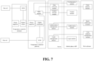
- the temperature controller gateway hardware mainly includes a network connection module, a processor, a real-time clock (RTC) clock, a temperature collection module (such as a temperature sensor), a light emitting diode (LED) indicator, a buzzer, a button, an external storage, a power supply module, and an liquid crystal display (LCD) touch screen.
- RTC real-time clock
- LED light emitting diode
- the network connection module is connected to the Internet and is responsible for communicating with the server on the Internet.
- the network connection module includes at least one wireless network module, and the network connection module may further include a wireless network module or a wired network module, where the wireless network module is preferably a WiFi network processor.
- the network connection module is responsible for receiving the configuration instruction of the temperature controller forwarded by the network processor and forwarding the configuration instruction to the temperature controller gateway.
- the wired network module and the wireless network module transfer data to each other through the processor, and convert the data through a customized protocol. If the wireless network module has the function of connecting to the Internet, the network processor for connecting to the Internet may be removed from the gateway device hardware.
- the wireless network module may be configured with a power amplifier configured to amplify the wireless signal of the wireless network module, so that the wireless signal is transmitted farther; certainly, the power amplifier may also be configured in the wired network module.
- a processor is configured to control the signal lines of the fan coil and to connect the various hardware modules.
- the RTC clock module is configured to perform timing and obtain server time in real time for time check.
- the temperature collection module is configured to collect ambient temperature.
- the LED indicator is configured to indicate the running state of the temperature controller and the network state.
- the buzzer is configured for device identification during networking.
- the external storage is configured to store the fan coil control program, the running version files of each chip and some key data of the temperature controller during running.
- the button is mainly configured to have functions of configuring a state of the temperature controller, resetting the device, and restoring the factory configurations.
- the power supply module is configured to power the device.
- the LCD touch screen is an optional module, and is configured to display the state of the temperature controller and configure the temperature controller. If the user requires the usage habits of the conventional temperature controller panel to be compatible, the LCD touch screen is configured; if the user is more accustomed to using the control terminal for remote operation, the LCD touch screen is not configured.
- the temperature controller gateway itself is also a temperature controller. Compared with the temperature controller terminal, one more network processor exists, and the performance configurations of the wireless network module and the performance configurations of other hardware are stronger than those of the terminal device. According to the needs of the user, the gateway may be independent, and the function of the temperature controller is not integrated. Each temperature controller system requires at least one gateway device or multiple gateway devices may be deployed.
- the hardware of the temperature controller terminal device mainly includes a wireless network module, a processor, an RTC clock, a temperature collection module, an LED indicator, a buzzer, an external storage, a button, a power supply module, an LCD touch screen, and may also include a timing switch module, a lock and unlock module, a statistics module, and a reporting module.
- the wireless network module has a Mesh (wireless grid network) network function
- the wireless network module is configured to communicate with the wireless network module of the gateway device or the wireless network module of the next hop.
- Other components have the same function as a gateway component.
- Each temperature controller system has zero, one or multiple terminal devices. The temperature controller is installed in the range of about 1 meter from the fan coil outlet to save wiring.
- the timing switch function is configured by the user in the APP of the control terminal (such as a mobile phone).
- the software module of the temperature controller terminal stores the configurations, and after the time point configured by the user is reached, the switch-on and switch-off configurations are automatically performed on the temperature controller.
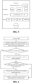
- An example of the main interface and an example of the configuration interface of the APP are shown in FIG. 4 and FIG. 5 respectively.
- the wireless network module is mainly responsible for wireless communication and data forwarding.
- the wireless network module includes network processor software and a network processor, and is mainly responsible for performing protocol conversion between the wireless network module and the network processor, reporting the heartbeat to the server, collecting the online state of each temperature controller terminal and ambient temperature, and other functions.
- the temperature collection module starts to periodically collect the ambient temperature data.
- the temperature controller terminal automatically configures the running state, temperature, and gear of the temperature controller by determining the change of the ambient temperature.
- temperature collection uses a manner of sampling for multiple times to determine the running of the temperature controller terminal. If the number of rises of the sampled temperature at the time of switch-on is greater than the number of drops of the sampled temperature, it is considered to be the hot wind, and the jitter data caused by external factors is discarded (a similar strategy is used for determining the cold wind).
- the temperature controller terminal is automatically configured to be a default cooling temperature. If the ambient temperature is lower than the default cooling temperature, the solenoid valve is closed and fan of the fan coil is turned off. If the ambient temperature is higher than the default cooling temperature, the gear of the fan is configured according to the magnitude of difference between the ambient temperature and the configured temperature.
- the temperature of the temperature controller is automatically configured to be a default heating temperature. If the ambient temperature is higher than the default heating temperature, the solenoid valve is closed and the fan of the fan coil is turned off. If the ambient temperature is lower than the default heating temperature, the gear of the fan is configured according to the magnitude of difference between the ambient temperature and the configured temperature.
- the default cooling temperature of the system is 26°C
- the default heating temperature of the system is 20°C
- these values are also the government's recommended value for temperature configuration in the office area.
- the default configuration temperature may effectively reduce energy consumption of the central air conditioner, and in special cases, the user may configure other temperature values. After the user configures other temperature, the temperature for closing the solenoid valve of the fan coil and turning off the fan is automatically adjusted accordingly.
- the temperature controller terminal runs according to the configurations of the user, and the automatic mode does not take effect.
- the automatic mode takes effect again after the user selects the automatic mode.
- the software module of the temperature controller terminal includes the following program modules.
- An anti-shake module is configured to screen the effective change information of the collected temperature.
- a first determining module is configured to determine the change trend, e.g., higher or unchanged, of the ambient temperature after the temperature controller is turned on.
- a temperature mode automatic configuration module is configured to configure the running mode to heating when the first determining module indicates an increasing trend and configure the default heating temperature; configure the running mode to be cooling when the first determining module indicates a decreasing trend and configure the default cooling temperature (i.e., the target temperature); and configure the running mode to be ventilation when the first determining module indicates that the temperature is unchanged.
- a second determining module is configured to determine the difference between the ambient temperature and the default temperature under the decreasing trend; and determine the difference between the default temperature and the ambient temperature under the increasing trend.
- a fan gear automatic configuration module is configured to configure the fan gear to be a low speed when the first determining result indicates that the temperature is unchanged.
- the fan gear automatic configuration module is further configured to configure the working speed of the fan to be the third preset rate if the difference is greater than the preset temperature threshold T1. If the difference is less than the preset temperature threshold T2 and not less than 0, the working speed of the fan is configured to be the first preset rate.
- the working speed of the fan is configured to be the second preset rate; where the first preset rate is lower than the second preset rate, and the second preset rate is lower than the third preset rate; and the temperature threshold T2 is less than the temperature threshold T1.
- a switch-on and switch-off automatic configuration module is configured to configure the solenoid valve of the fan coil to be in a closed state when the difference is equal to 0.
- the difference is less than a preset temperature threshold T3
- the fan is configured to be in a turn-off state; where the temperature threshold T3 is less than 0.
- the solenoid valve of the fan coil when the temperature mode automatic configuration module configures the mode to be cooling and the temperature difference determined by the second determining module is 0, the solenoid valve of the fan coil is configured to be closed, when the temperature difference of the second determining module is lower than the configuration temperature T3, the fan of the fan coil is configured to be turned off, and after a period of turn-off, when the temperature difference determined by the second determining module is higher than the configuration temperature T4, the fan is automatically turned on and the solenoid valve automatically opens; when the temperature mode automatic configuration module configures the mode to be heating and the temperature difference of the second determining module is 0, the solenoid valve of the fan coil is configured to be closed, when the temperature difference of the second determining module is lower than the configuration temperature T3, the fan of the fan coil is configured to be turned off, and after a period of turn-off, when the temperature difference of the second determining module is higher than the configuration temperature T4, the fan is automatically turned on and the solenoid valve automatically opens.
- the processor is configured to control the temperature controller and connect the hardware components of the temperature controller; and is configured to respond to the configuration instructions of various temperature, modes, gears and switches of the control terminal APP and control the running of the fan coil.
- the timing switch module is configured to automatically switch on or switch off after the timing switch-on/-off time configured by the user is up.
- the lock and unlock module is configured to, after the administrator locks the temperature controller, not allow other users to perform remote configuration on the temperature controller, and also not allow configuration of buttons on the LCD panel.
- the statistics module is configured to automatically count the daily running time of the temperature controller in various modes and gears, and obtain the running data of the temperature controller.
- the reporting module is configured to report the running data of the temperature controller terminal to the server.
- the server is mainly responsible for communication with the temperature controller terminal device, the temperature controller gateway device and the control terminal; the server is also responsible for the user's login authority management, user authorization management and user operation log statistics.
- the server is generally deployed on a cloud server or deployed on a server built by itself.
- the server includes a statistical data storage module, an operation log storage module, an authority management module, a statistical data charting module and an operation log query module.
- the statistical data storage module is configured to store statistical data of the temperature control apparatus in a database.
- the operation log storage module is configured to store the user's remote operation record in an operation log.
- the authority management module is configured to send information of the authorized devices to the control terminal when the control terminal requests a device list.
- the statistical data charting module is configured to plot data in the database into a chart on the management software.
- the operation log query module is configured for an administrator to query the above operation log.3.
- the control terminal displays the state of the temperature control apparatus, controls the temperature control apparatus, responds to various operations of the user, configures the installation address and name of the temperature control apparatus, and configures the timing switch time of the temperature control apparatus through the APP.
- the network processor of the temperature controller gateway device is a WiFi network processor
- the control terminal is also responsible for configuring the connection between the WiFi module of the gateway and the wireless router.
- the control terminal may also intelligently select whether to communicate with the gateway in the local area network directly or through the server according to the network condition.
- the APP mainly includes the Android platform and the IOS platform, and the platform may also be extended to other smartphone platforms.
- control terminal may include a temperature controller monitoring module, a timer configuration module, an authorization module, a configuration module, a batch configuration module and an automatic determining internal or external network module.
- the temperature controller monitoring module is configured to view and configure the state of the temperature control apparatus for the user.
- the timer configuration module is configured to configure timing switch-on/-off for the temperature control apparatus by the user.
- the authorization module is configured for an administrator to give other users the authorization of certain specified temperature control apparatuses.
- the configuration module is configured for the administrator to configure the address and name of a newly installed temperature control apparatus.
- the batch configuration module is configured for the administrator to configure multiple temperature control apparatuses at one time.
- the automatic determining internal or external network module has following functions.
- the control of the temperature control apparatus automatically takes the local area network control, and transfer through the server is not needed;
- the temperature control apparatus and the control terminal are not in the same local area network, transfer through the server is needed; and the internal network or the external network is automatically determined by the APP and does not need to be configured by the user.
- the mobile phone as the control terminal is taken as an example, and the process is shown in FIG. 6 .
- step 1 an app is started.
- step 2 it is initially configured that the control command of the temperature controller is forwarded by a server, and a network of the mobile phone is detected.
- step 3 whether the mobile phone is connected to WiFi is determined. If the mobile phone is connected to WiFi, step 4 is executed, and if the mobile phone is not connected to WiFi, step 7 is executed.
- gateway messages are searched for by broadcasting in a local area network.
- step 5 whether a gateway device gives a response in the local area network is determined. If a gateway device gives a response, step 6 is executed, if no gateway device gives a response, step 7 is executed.
- step 6 communication flags of all devices under the gateway are configured to be in an internal network mode.
- step 7 control commands of the mobile phone are forwarded by the server.
- the system may also include a management software module which includes a web server and a client module.
- the management software module is configured to manage deletion, modification, authorization and the like of the temperature controller, make switch-on time statistics of the temperature controller and perform charting, make operation log statistics of the temperature controller, and the like.
- the management software module mainly communicates with the server.
- the management software module may also use management software having C/S architecture.
- the system in the embodiment of the present invention has the following technical effects.
- the operation of a single temperature control apparatus is achieved on a mobile phone.
- the network processor in the gateway hardware of the temperature controller utilizes the WiFi module of the ESP8266 chip, and the wireless network module utilizes the CC2538 module as the ZigBee coordinator.
- the wireless network module in the hardware of the temperature controller terminal utilizes the CC2530 module as the Zigbee router.
- the processor utilizes Xintang 0516 single chip microcomputer.
- the operation flow includes the following steps.
- step 1 an app is started.
- step 2 an APP user logs in; the APP user may login to the APP with the mobile phone number of the APP user itself, and obtain an short-message verification code as a login password.
- the server verifies whether the verification code is correct, and after the verification is passed, the user logs in successfully.
- step 3 server configuration is requested.
- step 4 the server determines whether the control authority of the temperature controller exists. After the user logs in successfully, the server finds out in the server which temperature controller devices the user has control authority according to the user's mobile phone number, and returns the list of authorized devices to the APP. The APP displays the list of devices on the APP interface. If the user does not have an authorized device, step 14 is executed.
- step 5 the APP obtains the device list and queries the online state of the device, as shown in FIG. 4 .
- step 6 whether the device is online is determined. If the device is online, the user may enter the APP configuration interface and add a new device in the configuration interface. If a new temperature controller device currently exists, after the button of add new device is clicked, the new temperature controller will be displayed in the interface to be configured. After the button of enter is clicked, the new temperature controller may be named and configured, and after configuration is completed, step 7 is executed. If the device is not online, step 13 is executed.
- step 7 the real-time state of the device is queried.
- the state of the temperature controller mainly includes the state of a fan speed (high speed, medium speed, and low speed), current ambient temperature, configuration temperature of the temperature control apparatus, the mode state (automatic, cooling, heating, ventilation) of the temperature control apparatus, the switch state and the lock state.
- step 8 whether the device is locked is determined. If the device is locked, step 12 is executed; if the device is not locked, step 9 is executed.
- step 9 whether the device needs to be controlled is determined. If the device needs to be controlled, step 11 is executed; if the device does not need to be controlled, step 10 is executed.
- step 10 each control button as shown in FIG. 5 is clicked.
- control of the temperature controller mainly includes fan speed configuration (high speed, medium speed, and low speed), temperature setting, mode configuration (automatic, cooling, heating, ventilation) of the temperature controller, switch configuration, timing switch configuration, and lock device configuration.
- the IEEE address of the device to be controlled is filled in the communication interface.
- the Zigbee coordinator module of the gateway device determines whether the IEEE address is its own address. If the IEEE address is its own address, the Zigbee coordinator module of the gateway device directly sends a command to the MCU to control the fan coil of the air conditioner. If the IEEE address is not its own address, the Zigbee coordinator of the gateway device originally encapsulates the control command of the APP, queries the routing table, and sends the control command to the next-hop zigbee router.
- the Zigbee router determines whether the destination IEEE address of the received control command is its own IEEE address. If the destination IEEE address of the received control command is its own IEEE address, the Zigbee router sends a command to the microcontroller unit (MCU) to control the fan coil of the air conditioner. If the destination IEEE address of the received control command is not its own IEEE address, the Zigbee router continues to send the control command to a next hop until the control command is sent to the corresponding Zigbee router.
- MCU microcontroller unit
- the mobile phone When the mobile phone sends the control command (i.e., the configuration instruction) to the temperature controller, the mobile phone checks the network connection manner of the control APP.
- the control command i.e., the configuration instruction
- the control command is forwarded through the server. If the mobile phone connection is in the mobile network manner, the control command is forwarded through the server. If the mobile phone connection is in the WiFi manner, the control APP scans the gateway devices in the local area network. If a gateway device gives a response in the local area network, the gateway is marked as an internet device, the communication between the control APP and the gateway device adopts the manner of direct communication in the local area network, and transfer through the server is not needed. The gateway device that does not give a response is marked as the external network device, and communicates with the device via transfer through the server.
- step 11 exiting is executed.
- step 12 if the temperature control apparatus is in a locked state, no other operation can be executed on the temperature control apparatus, and the administrator is contacted to release the locked state of the temperature control apparatus or exiting is executed.
- step 13 a not online state is displayed.
- step 14 the device is configured or the administrator is contacted for authorization. For example, if a new temperature controller device does not exist currently, the administrator is contacted to authorize the temperature controller usage authority for a user. The administrator authorizes the user through a control APP software or a web software.
- the control of multiple temperature controller devices (which may be all devices) on the smart phone at the same time is implemented.
- the embodiment is mainly used for the administrator to batch control the temperature controllers. The following steps are included.
- step A an APP user logs in.
- the APP user logs in to the APP with its own mobile phone number, and obtain a short-message verification code as a login password.
- the server verifies whether the verification code is correct, and after the verification is passed, the user logs in successfully.
- step B the APP obtains a list of devices.
- the APP finds out in the server which temperature controller devices the user has control authority according to the user's mobile phone number, the list of authorized devices is returned to the APP, and the APP displays the list of devices on the app interface.
- step C the user enters a batch configuration interface of the control APP.
- step D a batch control of the temperature controllers is executed.
- the batch control of the temperature controllers mainly includes fan speed configuration (high speed, medium speed, and low speed), temperature setting, mode configuration (automatic, cooling, heating, ventilation) of the temperature controller, switch configuration, timing switch configuration, and lock device configuration.
- the user After the user enters the batch configuration interface, the user selects multiple devices that need to be configured in batch. After the batch configuration button is clicked, the APP sends control commands one by one to the devices according to the solution in the embodiment 3.
- step A the device is energized.
- the power supply of the device is normal, and the hardware, software, and temperature sensors run normally.
- step B the device collects the ambient temperature.
- the temperature sensor of the device collects the ambient temperature every 5 seconds and records the collected temperature.
- step C the device is turned on.
- the user remotely operates the device with the mobile phone to be turned on and configures the device to be in an automatic mode (or the user remotely operates the device with the mobile phone to be turned on and the device enters the automatic mode by default if no operation is performed within a predetermined time) or the device is turned on automatically by the timer of the device.
- step D the device determines the change trend of the ambient temperature.
- step E If the ambient temperature is slowly decreasing, it is considered that the fan coil outlet gives out cold air, and the process proceeds to step E. If the ambient temperature is slowly increasing, it is considered that the fan coil outlet gives out hot air, and the process proceeds to step F. If the ambient temperature is unchanged, it is considered that the fan coil outlet gives out natural air, and the central air conditioner has no cooling or heating.
- the fan gear of the temperature controller is configured to low.
- step E the target temperature is automatically configured to 26 °C, and the mode is configured to a cooling state.
- the fan gear of the air conditioner is configured to a high-gear; if the ambient temperature is greater than 27 °C and less than 30 °C, the fan gear of the air conditioner is configured to a mid-gear; if the ambient temperature is greater than 26 °C and less than 27 °C, the fan gear of the air conditioner is configured to a low-gear; if the ambient temperature is less than 26 °C, the solenoid valve is closed; if the temperature continues to decrease after the solenoid valve is closed, the fan is turned off. After switch-off for some time, if the ambient temperature is greater than 26.5 °C, the solenoid valve is opened and the fan is turned on again.
- step F the target temperature is automatically configured to 20 °C, and the mode is configured to a heating state.
- the fan gear of the air conditioner is configured to a high-gear; if the ambient temperature is greater than 16 °C and less than 19 °C, the fan gear of the air conditioner is configured to a mid-gear; if the ambient temperature is greater than 19°C and less than 20°C, the fan gear of the air conditioner is configured to a low-gear; if the ambient temperature is greater than 20 °C, the solenoid valve is closed; if the temperature continues to increase after the solenoid valve is closed, the fan is turned off. After switch-off for some time, if the ambient temperature is less than 19.5 °C, the solenoid valve is opened and the fan is turned on again.
- the control of a single temperature control apparatus on a smart phone is implemented.
- the wireless communication technology of the temperature control apparatus adopts narrow band-internet of things (NB-IoT), the subscriber identity module (SIM) card with the NB-IoT chip is installed on the temperature control apparatus, and the temperature control apparatus periodically reports a heartbeat to the server, where the heartbeat includes a hardware address of the SIM card.
- NB-IoT narrow band-internet of things
- SIM subscriber identity module
- step A an APP user logs in.
- the APP user logs in to an APP with its own mobile phone number, and obtains a short-message verification code as a login password.
- the server verifies whether the verification code is correct, and after the verification is passed, the user logs in successfully.
- step B the APP obtains a list of devices.
- the APP finds out in the server which temperature control apparatuses the user has control authority according to the user's mobile phone number, the list of authorized devices is returned to the app, and the APP displays the list of devices on the app interface.
- step C the state of the temperature control apparatus is queried.
- the state of the temperature control apparatus mainly includes the state of the fan speed (high speed, medium speed, and low speed), current ambient temperature, configuration temperature of the temperature control apparatus, the mode state (automatic, cooling, heating, ventilation) of the temperature control apparatus , the switch state and the lock state.
- step D a control of the temperature control apparatus is executed.
- the control of the temperature control apparatus mainly includes fan speed configuration (high speed, medium speed, and low speed), temperature setting, mode configuration (automatic, cooling, heating, ventilation) of the temperature control apparatus, switch configuration, timing switch configuration and lock device configuration.
- the NB-IoT hardware address of the controlled temperature control apparatus is filled in the communication interface and a control command is sent to the server.
- the server forwards the control command to the corresponding temperature control apparatus by checking the mapping table of the hardware address and the network address.
- the control of a single temperature control apparatus on a smart phone is implemented.
- the wireless communication technology of the temperature controller adopts LoRa
- a LoRa network processor is installed on the temperature controller, and the LoRa network processor periodically reports a heartbeat to the server, where the heartbeat includes a hardware address of the LoRa.
- the data processing method includes the following steps, and the hardware address belongs to one of the temperature control apparatus identifiers.
- step A an APP user logs in.
- the APP user logs in to an APP with its own mobile phone number, and obtains a short-message verification code as a login password.
- the server verifies whether the verification code is correct, and after the verification is passed, the user logs in successfully.
- step B the APP obtains a list of devices.
- the APP finds out in the server which temperature control apparatuses the user has control authority according to the user's mobile phone number, the list of authorized apparatuses is returned to the APP, and the APP displays the list of devices on the app interface.
- step C the state of the temperature control apparatus is queried.
- the state of the temperature control apparatus mainly includes the state of the fan speed (high speed, medium speed, and low speed), current ambient temperature, configuration temperature of the temperature controller, the mode state (automatic, cooling, heating, ventilation) of the temperature controller, the switch state, and the lock state.
- step D a control of the temperature control apparatus is executed.
- the control of the temperature control apparatus mainly includes fan speed configuration (high speed, medium speed, and low speed), temperature setting, mode configuration (automatic, cooling, heating, ventilation) of the temperature controller, switch configuration, timing switch configuration and lock device configuration.
- the LoRa hardware address of the device to be controlled is filled in the communication interface, and a control command is sent to the server.
- the server forwards the control command to the corresponding temperature controller by checking the mapping table of the hardware address and the network address.
- a method for controlling a fan coil is provided in an embodiment of the present invention and applied to a temperature control apparatus of an air conditioner, and the method includes the following steps.
- step S101 a running state is configured through a control terminal or is in an automatic mode.
- the step includes: if the temperature control apparatus is in a non-automatic working mode, a configuration instruction is received via a network, and the running state of the temperature control apparatus is configured according to the configuration instruction.
- ambient temperature is collected according to a set period; a change trend of the ambient temperature is determined according to the collected ambient temperature; and the running state of the temperature control apparatus is configured according to the change trend of the ambient temperature.
- step S 102 a corresponding control signal is sent to a fan coil connected with the temperature control apparatus according to the configured running state so as to enable the fan coil to start an action corresponding to the running state.
- the running state of the temperature control apparatus is configured through the control terminal, or the running state of the temperature control apparatus is automatically configured according to the change trend of the ambient temperature, so the problem that the existing temperature controller needs manual configuration is effectively solved and the control convenience of the existing temperature controller is improved.
- the step of determining a change trend of the ambient temperature according to the collected ambient temperature includes the following steps.
- the change trend of the ambient temperature is determined according to the ambient temperature of the each period node.
- the running state includes a cooling state, a heating state, and a ventilation state.
- the step of configuring the running state of the temperature control apparatus according to the change trend of the ambient temperature includes the following steps.
- the running state of the temperature control apparatus is configured to the cooling state, and a target cooling temperature is configured.
- the running state of the temperature control apparatus is configured to the heating state, and a target heating temperature is configured.
- the running state of the temperature control apparatus is configured to the ventilation state.
- the determining manner of the change trend of the ambient temperature includes the following manners.
- the change trend of the ambient temperature is the decreasing trend.
- the change trend of the ambient temperature is the increasing trend.
- the change trend of the ambient temperature is the flat trend.
- the working speed of the fan of the fan coil is configured to a low speed; where the working speed includes a low speed, a medium speed, and a high speed.
- a working speed of a fan of the fan coil is configured according to a difference in the decreasing trend or the increasing trend, where in the decreasing trend, the difference is a difference between currently acquired ambient temperature and the target cooling temperature, and in the increasing trend, the difference is a difference between the target heating temperature and the currently acquired ambient temperature.
- the step of configuring a working speed of a fan of the fan coil according to a difference includes the following steps.
- the working speed of the fan is configured to the high speed.
- the working speed of the fan is configured to the low speed.
- the working speed of the fan is configured to the medium speed.
- the step of configuring a working speed of a fan of the fan coil according to a difference further includes the following steps.
- a solenoid valve of the fan coil is configured to be in a closed state.
- the fan When the difference is less than a preset temperature threshold T3, the fan is configured to be in a closed state; where the temperature threshold T3 is less than 0.
- the solenoid valve and the fun are configured to be in a switch-on state, where the temperature threshold T4 is greater than 0.
- the method further includes the following steps.
- Running data of the temperature control apparatus is determined, and the running data is sent to a preset server, so that the server generates an analysis chart.
- State data of the temperature control apparatus is sent to a control terminal that obtains control authority from the server.
- the step of receiving a configuration instruction via a network and configuring a running state of the temperature control apparatus according to the configuration instruction includes the following steps.
- the configuration instruction is received via the network, and a temperature control apparatus identifier is parsed from the configuration instruction, where the configuration instruction is any one of: a control instruction directly sent by the control terminal to the temperature control apparatus or the control instruction of the control terminal forwarded by the server to the temperature control apparatus.
- the running state of the temperature control apparatus is configured according to the configuration instruction.
- the temperature control apparatus identifier is a network address of the temperature control apparatus.
- the method Before the step of receiving the configuration instruction via a network and parsing a temperature control apparatus identifier from the configuration instruction, the method further includes the following steps.
- Heartbeat data is reported to the server, so that when the control instruction of the control terminal is received, the server forwards the received control instruction of the control terminal to a corresponding temperature control apparatus according to a preset mapping table of hardware addresses and network addresses, where the heartbeat data carries a hardware address of the temperature control apparatus.
- a computer-readable storage medium stores a fan coil control program which, when executed by at least one processor, implements the steps of any method in the embodiment 8.
- the computer readable storage medium in embodiments of the present invention may be a random access memory (RAM) memory, a flash memory, a read-only memory (ROM), an Erasable Programmable Read-Only Memory (EPROM) memory, an Electrically Erasable Programmable Read-only Memory (EEPROM) memory, a register, a hard disk, a removable hard drive, a compact disc read-only memory (CD-ROM), or any other form of storage medium known in the art.
- a storage medium may be coupled to the processor, so that the processor can read information from the storage medium and write information to the storage medium, or the storage medium may be a component of the processor.
- the processor and the storage medium may be located in an application specific integrated circuit.
- the devices and the methods disclosed in the embodiments of the present application may be implemented in other ways.
- the device embodiments described above are merely illustrative.
- the unit division is merely a logical function division, and, in practice, the unit division may be implemented in other ways.
- multiple units or components may be combined or may be integrated into another system, or some features may be omitted or not executed.
- coupling, direct coupling or communication connections between the presented or discussed components may be indirect coupling or communication connections, via interfaces, between devices or units, and may be electrical, mechanical or in other forms.
- the running state of the temperature control apparatus is configured through the control terminal, or the running state of the temperature control apparatus is automatically configured, so the problems that the existing temperature controller needs to be manually configured and that the configuration process is troublesome are effectively solved.
Landscapes
- Engineering & Computer Science (AREA)
- Chemical & Material Sciences (AREA)
- Combustion & Propulsion (AREA)
- Mechanical Engineering (AREA)
- General Engineering & Computer Science (AREA)
- Signal Processing (AREA)
- Physics & Mathematics (AREA)
- Fuzzy Systems (AREA)
- Mathematical Physics (AREA)
- Human Computer Interaction (AREA)
- Fluid Mechanics (AREA)
- Air Conditioning Control Device (AREA)
Claims (13)
- Verfahren zur Steuerung einer Gebläsespule, angewendet auf eine Temperatursteuerungseinrichtung einer zentralen Klimatisierungsanlage, wobei die Temperatursteuerungseinrichtung derart konfiguriert ist, dass sie sich in einem nicht automatischen Arbeitsmodus oder in einem automatischen Arbeitsmodus befindet, und dadurch gekennzeichnet, dass es Folgendes umfasst:in einem Fall, in dem sich die Temperatursteuerungseinrichtung in einem nicht automatischen Arbeitsmodus befindet, Empfangen (S101) einer Konfigurationsanweisung und Konfigurieren eines Betriebszustands der Temperatursteuerungseinrichtung gemäß der Konfigurationsanweisung;in einem Fall, in dem sich die Temperatursteuerungseinrichtung in einem automatischen Arbeitsmodus befindet, Erfassen von Umgebungstemperatur gemäß einer eingestellten Periode; Bestimmen eines Änderungstrends der Umgebungstemperatur gemäß der erfassten Umgebungstemperatur; und Konfigurieren (S101) des Betriebszustands der Temperatursteuerungseinrichtung gemäß dem Änderungstrend der Umgebungstemperatur; undSenden (S102) eines dem konfigurierten Betriebszustand entsprechenden Steuersignals an die mit der Temperatursteuerungseinrichtung verbundene Gebläsespule gemäß dem konfigurierten Betriebszustand, um der Gebläsespule Starten einer dem Betriebszustand entsprechenden Aktion zu ermöglichen;wobei der Betriebszustand einen Kühlungszustand, einen Heizungszustand und einen Lüftungszustand umfasst;wobei das Konfigurieren (S101) des Betriebszustands der Temperatursteuerungseinrichtung gemäß dem Änderungstrend der Umgebungstemperatur Folgendes umfasst:als Reaktion auf Bestimmen, dass der Änderungstrend der Umgebungstemperatur ein abfallender Trend ist, Konfigurieren des Betriebszustands der Temperatursteuerungseinrichtung mit dem Kühlungszustand und Konfigurieren einer Soll-Kühlungstemperatur;als Reaktion auf Bestimmen, dass der Änderungstrend der Umgebungstemperatur ein ansteigender Trend ist, Konfigurieren des Betriebszustands der Temperatursteuerungseinrichtung mit dem Heizungszustand und Konfigurieren einer Soll-Heizungstemperatur; undals Reaktion auf Bestimmen, dass der Änderungstrend der Umgebungstemperatur ein flacher Trend ist, Konfigurieren des Betriebszustands der Temperatursteuerungseinrichtung mit dem Lüftungszustand.
- Verfahren nach Anspruch 1, wobei das Bestimmen eines Änderungstrends der Umgebungstemperatur gemäß der erfassten Umgebungstemperatur Folgendes umfasst:Erlangen von erfasster Umgebungstemperatur an jedem einer Vielzahl Periodenknoten; undBestimmen des Änderungstrends der Umgebungstemperatur gemäß der Umgebungstemperatur an den Periodenknoten.
- Verfahren nach Anspruch 1, wobei der Änderungstrend der Umgebungstemperatur auf eine der folgenden Weisen bestimmt wird:während eines voreingestellten Bestimmungszeitraums ist der Änderungstrend der Umgebungstemperatur als Reaktion auf Bestimmen, dass eine abfallende Amplitude der Umgebungstemperatur einen voreingestellten Kühlungsschwellenwert erreicht, der abfallende Trend;während des voreingestellten Bestimmungszeitraums ist der Änderungstrend der Umgebungstemperatur als Reaktion auf Bestimmen, dass eine ansteigende Amplitude der Umgebungstemperatur einen voreingestellten Heizungsschwellenwert erreicht, der ansteigende Trend; undwährend des voreingestellten Bestimmungszeitraums ist der Änderungstrend der Umgebungstemperatur als Reaktion auf Bestimmen, dass eine Änderungsamplitude der Umgebungstemperatur innerhalb eines voreingestellten Lüftungsschwellenwertbereichs liegt, der flache Trend.
- Verfahren nach Anspruch 1, wobei nach dem Konfigurieren des Betriebszustands der Temperatursteuerungseinrichtung gemäß dem Änderungstrend der Umgebungstemperatur das Verfahren ferner Folgendes umfasst:
Konfigurieren einer Arbeitsdrehzahl eines Gebläses der Gebläsespule gemäß einem Unterschied bei dem abfallenden Trend oder dem ansteigenden Trend, wobei der Unterschied bei dem abfallenden Trend ein Unterschied zwischen aktuell erlangter Umgebungstemperatur und der Soll-Kühlungstemperatur ist, und der Unterschied bei dem ansteigenden Trend der Unterschied zwischen der Soll-Heizungstemperatur und der aktuell erlangten Umgebungstemperatur ist. - Verfahren nach Anspruch 4, wobei das Konfigurieren einer Arbeitsdrehzahl eines Gebläses der Gebläsespule gemäß einem Unterschied Folgendes umfasst:als Reaktion auf Bestimmen, dass der Unterschied größer als ein voreingestellter erster Temperaturschwellenwert ist, Konfigurieren der Arbeitsdrehzahl des Gebläses mit einer dritten voreingestellten Rate;als Reaktion auf Bestimmen, dass der Unterschied kleiner als ein voreingestellter zweiter Temperaturschwellenwert und nicht kleiner als 0 ist, Konfigurieren der Arbeitsdrehzahl des Gebläses mit einer ersten voreingestellten Rate; undals Reaktion auf Bestimmen, dass der Unterschied nicht kleiner als der zweite Temperaturschwellenwert und nicht größer als der erste Temperaturschwellewert ist, Konfigurieren der Arbeitsdrehzahl des Gebläses mit einer zweiten voreingestellten Rate; wobei die erste voreingestellte Rate kleiner als die zweite voreingestellte Rate ist und die zweite voreingestellte Rate kleiner als die dritte voreingestellte Rate ist; und der zweite Temperaturschwellenwert kleiner als der erste Temperaturschwellenwert ist.
- Verfahren nach Anspruch 5, wobei das Konfigurieren einer Arbeitsdrehzahl eines Gebläses der Gebläsespule gemäß einem Unterschied ferner Folgendes umfasst:als Reaktion auf Bestimmen, dass der Unterschied gleich 0 ist, Konfigurieren eines Magnetventils der Gebläsespule, sich in einem geschlossenen Zustand zu befinden; undals Reaktion auf Bestimmen, dass der Unterschied kleiner als ein voreingestellter dritter Temperaturschwellenwert ist, Konfigurieren des Gebläses, sich in einem geschlossenen Zustand zu befinden; wobei der dritte Temperaturschwellenwert kleiner als 0 ist.
- Verfahren nach Anspruch 6, wobei nach dem Konfigurieren des Gebläses, sich in einem geschlossenen Zustand zu befinden, als Reaktion auf Bestimmen, dass der Unterschied kleiner als ein voreingestellter dritter Temperaturschwellenwert ist, das Verfahren ferner Folgendes umfasst:
als Reaktion auf Bestimmen, dass der Unterschied innerhalb eines voreingestellten Zeitraums größer als ein voreingestellter vierter Temperaturschwellenwert ist, Konfigurieren des Magnetventils, sich in einem Einschaltzustand zu befinden, und des Lüfters, sich in einem Einschaltzustand zu befinden; wobei der vierte Temperaturschwellenwert größer als 0 ist. - Verfahren nach Anspruch 1, ferner umfassend:Bestimmen von Betriebsdaten der Temperatursteuerungseinrichtung und Senden der Betriebsdaten an einen voreingestellten Server, sodass der Server ein Analysediagramm erzeugt; undSenden von Zustandsdaten der Temperatursteuerungseinrichtung an ein Steuerungsendgerät, das eine Steuerungsberechtigung von dem Server erhalten hat.
- Verfahren nach einem der Ansprüche 1 bis 8, wobei das Empfangen einer Konfigurationsanweisung und Konfigurieren eines Betriebszustands der Temperatursteuerungseinrichtung gemäß der Konfigurationsanweisung Folgendes umfasst:Empfangen der Konfigurationsanweisung über ein Netzwerk und Parsen einer Kennung der Temperatursteuerungseinrichtung aus der Konfigurationsanweisung; wobei die Konfigurationsanweisung eine beliebige ist von: einer Steuerungsanweisung, die direkt von dem Steuerungsendgerät an die Temperatursteuerungseinrichtung gesendet wird; oder der Steuerungsanweisung des Steuerungsendgeräts, die von dem Server an die Temperatursteuerungseinrichtung weitergeleitet wird; undals Reaktion auf Bestimmen, dass die geparste Kennung der Temperatursteuerungseinrichtung mit einer Kennung der Temperatursteuerungseinrichtung der Temperatursteuerungseinrichtung übereinstimmt, Konfigurieren des Betriebszustands der Temperatursteuerungseinrichtung gemäß der Konfigurationsanweisung.
- Verfahren nach Anspruch 9, wobei die Kennung der Temperatursteuerungseinrichtung eine Netzwerkadresse der Temperatursteuerungseinrichtung ist;
wobei das Verfahren vor dem Empfangen der Konfigurationsanweisung über ein Netzwerk und Parsen einer Kennung der Temperatursteuerungseinrichtung aus der Konfigurationsanweisung ferner Folgendes umfasst:
Melden von Heartbeat-Daten an den Server, sodass der Server als Reaktion auf Empfang der Steuerungsanweisung des Steuerungsendgeräts die empfangene Steuerungsanweisung des Steuerungsendgeräts an eine Temperatursteuerungseinrichtung gemäß einer voreingestellten Abbildungstabelle von Hardware-Adressen und Netzwerkadressen weiterleitet; wobei die Heartbeat-Daten eine Hardware-Adresse der Temperatursteuerungseinrichtung tragen. - Temperatursteuerungseinrichtung einer zentralen Klimatisierungsanlage, gekennzeichnet durch Umfassen eines Temperaturerfassungsmoduls, eines Speichers und eines Prozessors;wobei das Temperaturerfassungsmodul derart konfiguriert ist, dass es Umgebungstemperatur gemäß einer eingestellten Periode erfasst;wobei die Temperatursteuerungseinrichtung derart konfiguriert ist, dass sie sich in einem nicht automatischen Arbeitsmodus oder in einem automatischen Arbeitsmodus befindet;wobei der Speicher derart konfiguriert ist, dass er ein Gebläsespulensteuerungsprogramm speichert, und der Prozessor derart konfiguriert ist, dass er das Gebläsespulensteuerungsprogramm zum Implementieren der folgenden Schritte ausführt:in einem Fall, in dem sich die Temperatursteuerungseinrichtung in einem nicht automatischen Arbeitsmodus befindet, Empfangen einer Konfigurationsanweisung und Konfigurieren eines Betriebszustands der Temperatursteuerungseinrichtung gemäß der Konfigurationsanweisung;in einem Fall, in dem sich die Temperatursteuerungseinrichtung in einem automatischen Arbeitsmodus befindet, Bestimmen eines Änderungstrends der Umgebungstemperatur gemäß der erfassten Umgebungstemperatur; und Konfigurieren des Betriebszustands der Temperatursteuerungseinrichtung gemäß dem Änderungstrend der Umgebungstemperatur; undSenden eines dem konfigurierten Betriebszustand entsprechenden Steuersignals an eine mit der Temperatursteuerungseinrichtung verbundene Gebläsespule gemäß dem konfigurierten Betriebszustand, um der Gebläsespule den Start einer dem Betriebszustand entsprechenden Aktion zu ermöglichen;wobei der Betriebszustand einen Kühlungszustand, einen Heizungszustand und einen Lüftungszustand umfasst;wobei das Konfigurieren des Betriebszustands der Temperatursteuerungseinrichtung gemäß dem Änderungstrend der Umgebungstemperatur Folgendes umfasst:als Reaktion auf Bestimmen, dass der Änderungstrend der Umgebungstemperatur ein abfallender Trend ist, Konfigurieren des Betriebszustands der Temperatursteuerungseinrichtung mit dem Kühlungszustand und Konfigurieren einer Soll-Kühlungstemperatur;als Reaktion auf Bestimmen, dass der Änderungstrend der Umgebungstemperatur ein ansteigender Trend ist, Konfigurieren des Betriebszustands der Temperatursteuerungseinrichtung mit dem Heizungszustand und Konfigurieren einer Soll-Heizungstemperatur; undals Reaktion auf Bestimmen, dass der Änderungstrend der Umgebungstemperatur ein flacher Trend ist, Konfigurieren des Betriebszustands der Temperatursteuerungseinrichtung mit dem Lüftungszustand.
- Temperatursteuerungseinrichtung nach Anspruch 11, wobei das Bestimmen eines Änderungstrends der Umgebungstemperatur gemäß der erfassten Umgebungstemperatur Folgendes umfasst:Erlangen von erfasster Umgebungstemperatur an jedem einer Vielzahl von Periodenknoten; undBestimmen des Änderungstrends der Umgebungstemperatur gemäß der Umgebungstemperatur an den Periodenknoten.
- Computerlesbares Speichermedium zum Speichern eines Gebläsespulensteuerungsprogramms, das, wenn es von mindestens einem Prozessor der Temperatursteuerungseinrichtung nach Anspruch 11 ausgeführt wird, die Schritte des Verfahrens nach einem der Ansprüche 1 bis 10 implementiert.
Applications Claiming Priority (2)
| Application Number | Priority Date | Filing Date | Title |
|---|---|---|---|
| CN201710400466.4A CN108981092B (zh) | 2017-05-31 | 2017-05-31 | 中央空调温控装置、风机盘管的控制方法、介质及系统 |
| PCT/CN2018/088292 WO2018219213A1 (zh) | 2017-05-31 | 2018-05-24 | 中央空调温控装置、风机盘管的控制方法、介质及系统 |
Publications (3)
| Publication Number | Publication Date |
|---|---|
| EP3633281A1 EP3633281A1 (de) | 2020-04-08 |
| EP3633281A4 EP3633281A4 (de) | 2021-03-10 |
| EP3633281B1 true EP3633281B1 (de) | 2023-12-27 |
Family
ID=64456503
Family Applications (1)
| Application Number | Title | Priority Date | Filing Date |
|---|---|---|---|
| EP18810374.1A Active EP3633281B1 (de) | 2017-05-31 | 2018-05-24 | Zentrale klimatisierungstemperatursteuerungsvorrichtung, gebläsespulensteuerungsverfahren, medium und system |
Country Status (3)
| Country | Link |
|---|---|
| EP (1) | EP3633281B1 (de) |
| CN (1) | CN108981092B (de) |
| WO (1) | WO2018219213A1 (de) |
Families Citing this family (19)
| Publication number | Priority date | Publication date | Assignee | Title |
|---|---|---|---|---|
| CN109933023B (zh) * | 2018-12-19 | 2024-02-13 | 吉林大学 | 基于低功耗广域网的网联车管理系统 |
| CN109812933B (zh) * | 2019-01-28 | 2020-09-11 | 北京国马斯尔福实验室设备有限责任公司 | 实验室智能化控制系统 |
| CN110986306B (zh) * | 2019-11-30 | 2021-06-08 | 远景智能国际私人投资有限公司 | 基于机器学习的室温调节的方法、装置、设备及存储介质 |
| CN114698319B (zh) * | 2020-12-29 | 2025-04-01 | 北京金风科创风电设备有限公司 | 变流器散热系统及其控制方法、变流器以及风力发电机组 |
| CN115134460B (zh) * | 2021-03-29 | 2024-07-23 | 北京小米移动软件有限公司 | 一种移动终端温度控制方法、装置、终端及存储介质 |
| CN113218052B (zh) * | 2021-05-14 | 2022-12-16 | 广州市设计院集团有限公司 | 温度调节方法、装置、计算机设备和存储介质 |
| CN113606753B (zh) * | 2021-07-19 | 2023-01-10 | 启北公司 | 温控器功能配置方法、装置、计算机设备及可读存储介质 |
| CN113608596B (zh) * | 2021-07-29 | 2024-05-24 | 上海德衡数据科技有限公司 | 一种服务器智能冷却方法及系统 |
| CN114615291A (zh) * | 2021-12-08 | 2022-06-10 | 江苏众亿国链大数据科技有限公司 | 一种基于物联网的数据采集方法 |
| CN114383269A (zh) * | 2021-12-31 | 2022-04-22 | 无锡军创工程技术有限公司 | 基于云平台的中央空调节能控制方法与系统 |
| CN114963463A (zh) * | 2022-06-15 | 2022-08-30 | 广州市设计院集团有限公司 | 风机盘管运行控制方法、装置、系统及空调机组 |
| CN115371223A (zh) * | 2022-07-25 | 2022-11-22 | 绿碳智能建筑(杭州)有限公司 | 一种温控器面板及其温度控制方法 |
| CN116592486B (zh) * | 2022-09-01 | 2025-11-25 | 众清智能科技(苏州)有限公司 | 温度控制方法、装置、设备及介质 |
| CN115599021B (zh) * | 2022-10-18 | 2023-11-17 | 无锡锐泰节能系统科学有限公司 | 风机能耗智能管控平台 |
| CN116697535B (zh) * | 2023-06-12 | 2025-12-12 | 青岛海信日立空调系统有限公司 | 一种集控器及空调控制方法 |
| CN116557330B (zh) * | 2023-07-11 | 2023-09-22 | 深圳盈特创智能科技有限公司 | 一种用于启动无反偏风筒的控制管理系统 |
| CN117949034B (zh) * | 2023-12-12 | 2024-08-09 | 江苏泰迪智能科技有限公司 | 基于数据分析的线激光测试台操作环境监管系统 |
| CN119333928B (zh) * | 2024-11-22 | 2025-10-28 | 珠海格力电器股份有限公司 | 风机盘管加热保护方法、装置、设备和存储介质 |
| CN120466818B (zh) * | 2025-07-17 | 2025-09-23 | 南京深度智控科技有限公司 | 一种基于深度强化学习的蒸发冷空调节能优化控制方法 |
Family Cites Families (17)
| Publication number | Priority date | Publication date | Assignee | Title |
|---|---|---|---|---|
| JP3128043B2 (ja) * | 1994-09-29 | 2001-01-29 | 鹿島建設株式会社 | ファンコイル装置の制御方法及びファンコイル装置 |
| CN1256546C (zh) * | 2001-12-25 | 2006-05-17 | 乐金电子(天津)电器有限公司 | 空调机自动转换冷/暖运转方式的方法 |
| JP4540333B2 (ja) * | 2003-12-18 | 2010-09-08 | 三菱電機株式会社 | 冷暖房自動切換システム |
| CN100414199C (zh) * | 2003-12-23 | 2008-08-27 | 乐金电子(天津)电器有限公司 | 无抖动的室温控制装置及其控制方法 |
| CN1322280C (zh) * | 2004-11-19 | 2007-06-20 | 杨东 | 智能型风机盘管 |
| KR100802159B1 (ko) * | 2006-08-29 | 2008-02-11 | 바스코리아 주식회사 | 실내온도의 최적 제어를 위한 팬코일 유닛 제어기 및팬코일 유닛 제어시스템 |
| CN201003837Y (zh) * | 2007-02-09 | 2008-01-09 | 上海元上电子科技有限公司 | 风机盘管限温温控器 |
| CN103188091A (zh) * | 2011-12-28 | 2013-07-03 | 英业达股份有限公司 | 云端服务系统的管理方法及管理系统 |
| CN203068732U (zh) * | 2012-12-14 | 2013-07-17 | 上海盈达空调设备有限公司 | 一种风机盘管系统 |
| KR101294291B1 (ko) * | 2013-01-09 | 2013-08-07 | 바스코리아 주식회사 | 공조 및 팬코일 제어 장치 |
| US9551501B2 (en) * | 2013-03-15 | 2017-01-24 | Honeywell International Inc. | Multi-mode auto changeover system |
| CN104596046B (zh) * | 2014-12-15 | 2017-09-12 | 福建求实智能股份有限公司 | 两管制空调的冬夏制切换方法 |
| CN104597763A (zh) * | 2015-01-21 | 2015-05-06 | 苏州奥莱维信息技术有限公司 | 一种基于手机控制的智能家居系统 |
| CN104570755A (zh) * | 2015-01-21 | 2015-04-29 | 苏州奥莱维信息技术有限公司 | 一种基于手机的智能家居控制方法 |
| CN105172819B (zh) * | 2015-08-07 | 2018-02-13 | 中国北车集团大连机车研究所有限公司 | 电力机车用空调电控系统及其控制方法 |
| CN105352139B (zh) * | 2015-12-08 | 2019-08-20 | 刘俊声 | 动态水力平衡末端风机盘管的控制方法 |
| CN106196463B (zh) * | 2016-07-20 | 2018-12-25 | 珠海格力电器股份有限公司 | 一种风机盘管自动控制方法及装置 |
-
2017
- 2017-05-31 CN CN201710400466.4A patent/CN108981092B/zh active Active
-
2018
- 2018-05-24 EP EP18810374.1A patent/EP3633281B1/de active Active
- 2018-05-24 WO PCT/CN2018/088292 patent/WO2018219213A1/zh not_active Ceased
Also Published As
| Publication number | Publication date |
|---|---|
| EP3633281A1 (de) | 2020-04-08 |
| WO2018219213A1 (zh) | 2018-12-06 |
| EP3633281A4 (de) | 2021-03-10 |
| CN108981092B (zh) | 2022-04-12 |
| CN108981092A (zh) | 2018-12-11 |
Similar Documents
| Publication | Publication Date | Title |
|---|---|---|
| EP3633281B1 (de) | Zentrale klimatisierungstemperatursteuerungsvorrichtung, gebläsespulensteuerungsverfahren, medium und system | |
| CN108415385B (zh) | 基于蓝牙通信的智能家居控制系统 | |
| US9471070B2 (en) | Environmental control system including distributed control elements | |
| CN104166396B (zh) | 一种智能家居控制方法及系统 | |
| CN103312827B (zh) | 基于移动网络的家居云端控制方法及系统 | |
| US20140135993A1 (en) | Method and apparatus for managing energy in home | |
| CN111025925A (zh) | 一种基于云计算的智能家居配备系统 | |
| US20090134969A1 (en) | System and method for transmitting and receiving information on a neighborhood area network | |
| HK1206500A1 (en) | Network control apparatus, intelligent household system and control method thereof | |
| CN205176636U (zh) | 基于云计算的智能家居监控系统 | |
| CN102170382A (zh) | 一种数字家庭中通过智能网络监控家居终端设备的系统 | |
| US20140343698A1 (en) | Device control apparatus, device control method, and device control system | |
| CN105091225A (zh) | 一种离线计算室内空调开机和温度超标的方法及其系统 | |
| CN205665603U (zh) | 一种温室环境远程智能监控系统 | |
| CN105867154A (zh) | 一种家居设备网络的控制设备及系统 | |
| CN105787835A (zh) | 一种智能校园宿舍管理系统 | |
| CN205536384U (zh) | 一种中央空调机组远程监控与控制系统 | |
| CN111811114A (zh) | 一种节能的空调智能控制系统 | |
| CN111108489A (zh) | 服务器、信息处理方法、网络系统以及空气净化器 | |
| CN205299841U (zh) | 一种基于网络的空调集中控制系统 | |
| KR102165151B1 (ko) | 에어컨을 제어하는 장치 및 방법 | |
| CN204442411U (zh) | 网络控制装置和智能家居系统 | |
| CN205119361U (zh) | 空调及其控制系统和远程服务器 | |
| CN208271384U (zh) | 一种智能家庭温控系统 | |
| CN105650832A (zh) | 一种基于物联网技术的外置感温空调 |
Legal Events
| Date | Code | Title | Description |
|---|---|---|---|
| STAA | Information on the status of an ep patent application or granted ep patent |
Free format text: STATUS: THE INTERNATIONAL PUBLICATION HAS BEEN MADE |
|
| PUAI | Public reference made under article 153(3) epc to a published international application that has entered the european phase |
Free format text: ORIGINAL CODE: 0009012 |
|
| STAA | Information on the status of an ep patent application or granted ep patent |
Free format text: STATUS: REQUEST FOR EXAMINATION WAS MADE |
|
| 17P | Request for examination filed |
Effective date: 20191231 |
|
| AK | Designated contracting states |
Kind code of ref document: A1 Designated state(s): AL AT BE BG CH CY CZ DE DK EE ES FI FR GB GR HR HU IE IS IT LI LT LU LV MC MK MT NL NO PL PT RO RS SE SI SK SM TR |
|
| A4 | Supplementary search report drawn up and despatched |
Effective date: 20210210 |
|
| RIC1 | Information provided on ipc code assigned before grant |
Ipc: F24F 11/80 20180101ALI20210204BHEP Ipc: F24F 110/10 20180101ALI20210204BHEP Ipc: F24F 11/67 20180101AFI20210204BHEP Ipc: F24F 120/00 20180101ALI20210204BHEP Ipc: F24F 11/64 20180101ALI20210204BHEP Ipc: F24F 11/58 20180101ALI20210204BHEP Ipc: F24F 11/30 20180101ALI20210204BHEP Ipc: F24F 11/77 20180101ALI20210204BHEP Ipc: F24F 11/49 20180101ALI20210204BHEP Ipc: F24F 11/62 20180101ALI20210204BHEP |
|
| GRAP | Despatch of communication of intention to grant a patent |
Free format text: ORIGINAL CODE: EPIDOSNIGR1 |
|
| STAA | Information on the status of an ep patent application or granted ep patent |
Free format text: STATUS: GRANT OF PATENT IS INTENDED |
|
| RIC1 | Information provided on ipc code assigned before grant |
Ipc: F24F 120/00 20180101ALI20230705BHEP Ipc: F24F 110/10 20180101ALI20230705BHEP Ipc: F24F 11/64 20180101ALI20230705BHEP Ipc: F24F 11/62 20180101ALI20230705BHEP Ipc: F24F 11/58 20180101ALI20230705BHEP Ipc: F24F 11/80 20180101ALI20230705BHEP Ipc: F24F 11/77 20180101ALI20230705BHEP Ipc: F24F 11/30 20180101ALI20230705BHEP Ipc: F24F 11/49 20180101ALI20230705BHEP Ipc: F24F 11/67 20180101AFI20230705BHEP |
|
| INTG | Intention to grant announced |
Effective date: 20230719 |
|
| GRAS | Grant fee paid |
Free format text: ORIGINAL CODE: EPIDOSNIGR3 |
|
| GRAA | (expected) grant |
Free format text: ORIGINAL CODE: 0009210 |
|
| STAA | Information on the status of an ep patent application or granted ep patent |
Free format text: STATUS: THE PATENT HAS BEEN GRANTED |
|
| AK | Designated contracting states |
Kind code of ref document: B1 Designated state(s): AL AT BE BG CH CY CZ DE DK EE ES FI FR GB GR HR HU IE IS IT LI LT LU LV MC MK MT NL NO PL PT RO RS SE SI SK SM TR |
|
| REG | Reference to a national code |
Ref country code: GB Ref legal event code: FG4D |
|
| REG | Reference to a national code |
Ref country code: CH Ref legal event code: EP |
|
| REG | Reference to a national code |
Ref country code: DE Ref legal event code: R096 Ref document number: 602018063308 Country of ref document: DE |
|
| REG | Reference to a national code |
Ref country code: IE Ref legal event code: FG4D |
|
| PG25 | Lapsed in a contracting state [announced via postgrant information from national office to epo] |
Ref country code: GR Free format text: LAPSE BECAUSE OF FAILURE TO SUBMIT A TRANSLATION OF THE DESCRIPTION OR TO PAY THE FEE WITHIN THE PRESCRIBED TIME-LIMIT Effective date: 20240328 |
|
| REG | Reference to a national code |
Ref country code: LT Ref legal event code: MG9D |
|
| PG25 | Lapsed in a contracting state [announced via postgrant information from national office to epo] |
Ref country code: LT Free format text: LAPSE BECAUSE OF FAILURE TO SUBMIT A TRANSLATION OF THE DESCRIPTION OR TO PAY THE FEE WITHIN THE PRESCRIBED TIME-LIMIT Effective date: 20231227 |
|
| PG25 | Lapsed in a contracting state [announced via postgrant information from national office to epo] |
Ref country code: ES Free format text: LAPSE BECAUSE OF FAILURE TO SUBMIT A TRANSLATION OF THE DESCRIPTION OR TO PAY THE FEE WITHIN THE PRESCRIBED TIME-LIMIT Effective date: 20231227 |
|
| PG25 | Lapsed in a contracting state [announced via postgrant information from national office to epo] |
Ref country code: LT Free format text: LAPSE BECAUSE OF FAILURE TO SUBMIT A TRANSLATION OF THE DESCRIPTION OR TO PAY THE FEE WITHIN THE PRESCRIBED TIME-LIMIT Effective date: 20231227 Ref country code: GR Free format text: LAPSE BECAUSE OF FAILURE TO SUBMIT A TRANSLATION OF THE DESCRIPTION OR TO PAY THE FEE WITHIN THE PRESCRIBED TIME-LIMIT Effective date: 20240328 Ref country code: FI Free format text: LAPSE BECAUSE OF FAILURE TO SUBMIT A TRANSLATION OF THE DESCRIPTION OR TO PAY THE FEE WITHIN THE PRESCRIBED TIME-LIMIT Effective date: 20231227 Ref country code: ES Free format text: LAPSE BECAUSE OF FAILURE TO SUBMIT A TRANSLATION OF THE DESCRIPTION OR TO PAY THE FEE WITHIN THE PRESCRIBED TIME-LIMIT Effective date: 20231227 Ref country code: BG Free format text: LAPSE BECAUSE OF FAILURE TO SUBMIT A TRANSLATION OF THE DESCRIPTION OR TO PAY THE FEE WITHIN THE PRESCRIBED TIME-LIMIT Effective date: 20240327 |
|
| REG | Reference to a national code |
Ref country code: NL Ref legal event code: MP Effective date: 20231227 |
|
| REG | Reference to a national code |
Ref country code: AT Ref legal event code: MK05 Ref document number: 1644863 Country of ref document: AT Kind code of ref document: T Effective date: 20231227 |
|
| PG25 | Lapsed in a contracting state [announced via postgrant information from national office to epo] |
Ref country code: NL Free format text: LAPSE BECAUSE OF FAILURE TO SUBMIT A TRANSLATION OF THE DESCRIPTION OR TO PAY THE FEE WITHIN THE PRESCRIBED TIME-LIMIT Effective date: 20231227 |
|
| PG25 | Lapsed in a contracting state [announced via postgrant information from national office to epo] |
Ref country code: SE Free format text: LAPSE BECAUSE OF FAILURE TO SUBMIT A TRANSLATION OF THE DESCRIPTION OR TO PAY THE FEE WITHIN THE PRESCRIBED TIME-LIMIT Effective date: 20231227 Ref country code: RS Free format text: LAPSE BECAUSE OF FAILURE TO SUBMIT A TRANSLATION OF THE DESCRIPTION OR TO PAY THE FEE WITHIN THE PRESCRIBED TIME-LIMIT Effective date: 20231227 Ref country code: NO Free format text: LAPSE BECAUSE OF FAILURE TO SUBMIT A TRANSLATION OF THE DESCRIPTION OR TO PAY THE FEE WITHIN THE PRESCRIBED TIME-LIMIT Effective date: 20240327 Ref country code: NL Free format text: LAPSE BECAUSE OF FAILURE TO SUBMIT A TRANSLATION OF THE DESCRIPTION OR TO PAY THE FEE WITHIN THE PRESCRIBED TIME-LIMIT Effective date: 20231227 Ref country code: LV Free format text: LAPSE BECAUSE OF FAILURE TO SUBMIT A TRANSLATION OF THE DESCRIPTION OR TO PAY THE FEE WITHIN THE PRESCRIBED TIME-LIMIT Effective date: 20231227 Ref country code: HR Free format text: LAPSE BECAUSE OF FAILURE TO SUBMIT A TRANSLATION OF THE DESCRIPTION OR TO PAY THE FEE WITHIN THE PRESCRIBED TIME-LIMIT Effective date: 20231227 |
|
| PG25 | Lapsed in a contracting state [announced via postgrant information from national office to epo] |
Ref country code: IS Free format text: LAPSE BECAUSE OF FAILURE TO SUBMIT A TRANSLATION OF THE DESCRIPTION OR TO PAY THE FEE WITHIN THE PRESCRIBED TIME-LIMIT Effective date: 20240427 |
|
| PG25 | Lapsed in a contracting state [announced via postgrant information from national office to epo] |
Ref country code: AT Free format text: LAPSE BECAUSE OF FAILURE TO SUBMIT A TRANSLATION OF THE DESCRIPTION OR TO PAY THE FEE WITHIN THE PRESCRIBED TIME-LIMIT Effective date: 20231227 Ref country code: CZ Free format text: LAPSE BECAUSE OF FAILURE TO SUBMIT A TRANSLATION OF THE DESCRIPTION OR TO PAY THE FEE WITHIN THE PRESCRIBED TIME-LIMIT Effective date: 20231227 |
|
| PG25 | Lapsed in a contracting state [announced via postgrant information from national office to epo] |
Ref country code: SK Free format text: LAPSE BECAUSE OF FAILURE TO SUBMIT A TRANSLATION OF THE DESCRIPTION OR TO PAY THE FEE WITHIN THE PRESCRIBED TIME-LIMIT Effective date: 20231227 |
|
| PG25 | Lapsed in a contracting state [announced via postgrant information from national office to epo] |
Ref country code: SM Free format text: LAPSE BECAUSE OF FAILURE TO SUBMIT A TRANSLATION OF THE DESCRIPTION OR TO PAY THE FEE WITHIN THE PRESCRIBED TIME-LIMIT Effective date: 20231227 Ref country code: SK Free format text: LAPSE BECAUSE OF FAILURE TO SUBMIT A TRANSLATION OF THE DESCRIPTION OR TO PAY THE FEE WITHIN THE PRESCRIBED TIME-LIMIT Effective date: 20231227 Ref country code: RO Free format text: LAPSE BECAUSE OF FAILURE TO SUBMIT A TRANSLATION OF THE DESCRIPTION OR TO PAY THE FEE WITHIN THE PRESCRIBED TIME-LIMIT Effective date: 20231227 Ref country code: IT Free format text: LAPSE BECAUSE OF FAILURE TO SUBMIT A TRANSLATION OF THE DESCRIPTION OR TO PAY THE FEE WITHIN THE PRESCRIBED TIME-LIMIT Effective date: 20231227 Ref country code: IS Free format text: LAPSE BECAUSE OF FAILURE TO SUBMIT A TRANSLATION OF THE DESCRIPTION OR TO PAY THE FEE WITHIN THE PRESCRIBED TIME-LIMIT Effective date: 20240427 Ref country code: EE Free format text: LAPSE BECAUSE OF FAILURE TO SUBMIT A TRANSLATION OF THE DESCRIPTION OR TO PAY THE FEE WITHIN THE PRESCRIBED TIME-LIMIT Effective date: 20231227 Ref country code: CZ Free format text: LAPSE BECAUSE OF FAILURE TO SUBMIT A TRANSLATION OF THE DESCRIPTION OR TO PAY THE FEE WITHIN THE PRESCRIBED TIME-LIMIT Effective date: 20231227 Ref country code: AT Free format text: LAPSE BECAUSE OF FAILURE TO SUBMIT A TRANSLATION OF THE DESCRIPTION OR TO PAY THE FEE WITHIN THE PRESCRIBED TIME-LIMIT Effective date: 20231227 |
|
| PG25 | Lapsed in a contracting state [announced via postgrant information from national office to epo] |
Ref country code: PL Free format text: LAPSE BECAUSE OF FAILURE TO SUBMIT A TRANSLATION OF THE DESCRIPTION OR TO PAY THE FEE WITHIN THE PRESCRIBED TIME-LIMIT Effective date: 20231227 Ref country code: PT Free format text: LAPSE BECAUSE OF FAILURE TO SUBMIT A TRANSLATION OF THE DESCRIPTION OR TO PAY THE FEE WITHIN THE PRESCRIBED TIME-LIMIT Effective date: 20240429 |
|
| PG25 | Lapsed in a contracting state [announced via postgrant information from national office to epo] |
Ref country code: PT Free format text: LAPSE BECAUSE OF FAILURE TO SUBMIT A TRANSLATION OF THE DESCRIPTION OR TO PAY THE FEE WITHIN THE PRESCRIBED TIME-LIMIT Effective date: 20240429 Ref country code: PL Free format text: LAPSE BECAUSE OF FAILURE TO SUBMIT A TRANSLATION OF THE DESCRIPTION OR TO PAY THE FEE WITHIN THE PRESCRIBED TIME-LIMIT Effective date: 20231227 |
|
| REG | Reference to a national code |
Ref country code: DE Ref legal event code: R097 Ref document number: 602018063308 Country of ref document: DE |
|
| PG25 | Lapsed in a contracting state [announced via postgrant information from national office to epo] |
Ref country code: DK Free format text: LAPSE BECAUSE OF FAILURE TO SUBMIT A TRANSLATION OF THE DESCRIPTION OR TO PAY THE FEE WITHIN THE PRESCRIBED TIME-LIMIT Effective date: 20231227 |
|
| PG25 | Lapsed in a contracting state [announced via postgrant information from national office to epo] |
Ref country code: DK Free format text: LAPSE BECAUSE OF FAILURE TO SUBMIT A TRANSLATION OF THE DESCRIPTION OR TO PAY THE FEE WITHIN THE PRESCRIBED TIME-LIMIT Effective date: 20231227 |
|
| PLBE | No opposition filed within time limit |
Free format text: ORIGINAL CODE: 0009261 |
|
| STAA | Information on the status of an ep patent application or granted ep patent |
Free format text: STATUS: NO OPPOSITION FILED WITHIN TIME LIMIT |
|
| 26N | No opposition filed |
Effective date: 20240930 |
|
| REG | Reference to a national code |
Ref country code: CH Ref legal event code: PL |
|
| PG25 | Lapsed in a contracting state [announced via postgrant information from national office to epo] |
Ref country code: MC Free format text: LAPSE BECAUSE OF FAILURE TO SUBMIT A TRANSLATION OF THE DESCRIPTION OR TO PAY THE FEE WITHIN THE PRESCRIBED TIME-LIMIT Effective date: 20231227 |
|
| PG25 | Lapsed in a contracting state [announced via postgrant information from national office to epo] |
Ref country code: LU Free format text: LAPSE BECAUSE OF NON-PAYMENT OF DUE FEES Effective date: 20240524 |
|
| PG25 | Lapsed in a contracting state [announced via postgrant information from national office to epo] |
Ref country code: MC Free format text: LAPSE BECAUSE OF FAILURE TO SUBMIT A TRANSLATION OF THE DESCRIPTION OR TO PAY THE FEE WITHIN THE PRESCRIBED TIME-LIMIT Effective date: 20231227 Ref country code: LU Free format text: LAPSE BECAUSE OF NON-PAYMENT OF DUE FEES Effective date: 20240524 Ref country code: CH Free format text: LAPSE BECAUSE OF NON-PAYMENT OF DUE FEES Effective date: 20240531 |
|
| REG | Reference to a national code |
Ref country code: BE Ref legal event code: MM Effective date: 20240531 |
|
| PG25 | Lapsed in a contracting state [announced via postgrant information from national office to epo] |
Ref country code: IE Free format text: LAPSE BECAUSE OF NON-PAYMENT OF DUE FEES Effective date: 20240524 |
|
| PG25 | Lapsed in a contracting state [announced via postgrant information from national office to epo] |
Ref country code: SI Free format text: LAPSE BECAUSE OF FAILURE TO SUBMIT A TRANSLATION OF THE DESCRIPTION OR TO PAY THE FEE WITHIN THE PRESCRIBED TIME-LIMIT Effective date: 20231227 Ref country code: BE Free format text: LAPSE BECAUSE OF NON-PAYMENT OF DUE FEES Effective date: 20240531 |
|
| PGFP | Annual fee paid to national office [announced via postgrant information from national office to epo] |
Ref country code: DE Payment date: 20250521 Year of fee payment: 8 |
|
| PGFP | Annual fee paid to national office [announced via postgrant information from national office to epo] |
Ref country code: FR Payment date: 20250528 Year of fee payment: 8 |
|
| PG25 | Lapsed in a contracting state [announced via postgrant information from national office to epo] |
Ref country code: CY Free format text: LAPSE BECAUSE OF FAILURE TO SUBMIT A TRANSLATION OF THE DESCRIPTION OR TO PAY THE FEE WITHIN THE PRESCRIBED TIME-LIMIT; INVALID AB INITIO Effective date: 20180524 |
|
| PG25 | Lapsed in a contracting state [announced via postgrant information from national office to epo] |
Ref country code: HU Free format text: LAPSE BECAUSE OF FAILURE TO SUBMIT A TRANSLATION OF THE DESCRIPTION OR TO PAY THE FEE WITHIN THE PRESCRIBED TIME-LIMIT; INVALID AB INITIO Effective date: 20180524 |
|
| PGFP | Annual fee paid to national office [announced via postgrant information from national office to epo] |
Ref country code: GB Payment date: 20260306 Year of fee payment: 9 |