EP3633317A2 - Systeme und verfahren für endgepumpte laserspiegelstapelanordnungen - Google Patents
Systeme und verfahren für endgepumpte laserspiegelstapelanordnungen Download PDFInfo
- Publication number
- EP3633317A2 EP3633317A2 EP19191607.1A EP19191607A EP3633317A2 EP 3633317 A2 EP3633317 A2 EP 3633317A2 EP 19191607 A EP19191607 A EP 19191607A EP 3633317 A2 EP3633317 A2 EP 3633317A2
- Authority
- EP
- European Patent Office
- Prior art keywords
- pump light
- mirror stack
- light
- injection layer
- assembly
- Prior art date
- Legal status (The legal status is an assumption and is not a legal conclusion. Google has not performed a legal analysis and makes no representation as to the accuracy of the status listed.)
- Withdrawn
Links
- 230000000712 assembly Effects 0.000 title abstract description 11
- 238000000429 assembly Methods 0.000 title abstract description 11
- 238000000034 method Methods 0.000 title abstract description 7
- 230000003287 optical effect Effects 0.000 claims abstract description 53
- 239000000758 substrate Substances 0.000 claims abstract description 53
- 238000002347 injection Methods 0.000 claims abstract description 52
- 239000007924 injection Substances 0.000 claims abstract description 52
- 239000000463 material Substances 0.000 claims abstract description 50
- 239000010409 thin film Substances 0.000 claims abstract description 47
- 239000006117 anti-reflective coating Substances 0.000 claims abstract description 15
- 239000002019 doping agent Substances 0.000 claims abstract description 7
- 238000000576 coating method Methods 0.000 claims description 21
- 239000011248 coating agent Substances 0.000 claims description 17
- 230000003667 anti-reflective effect Effects 0.000 claims description 8
- 229910052779 Neodymium Inorganic materials 0.000 claims description 4
- QEFYFXOXNSNQGX-UHFFFAOYSA-N neodymium atom Chemical compound [Nd] QEFYFXOXNSNQGX-UHFFFAOYSA-N 0.000 claims description 4
- 239000010410 layer Substances 0.000 description 74
- 238000010586 diagram Methods 0.000 description 11
- 239000000835 fiber Substances 0.000 description 9
- VYPSYNLAJGMNEJ-UHFFFAOYSA-N Silicium dioxide Chemical compound O=[Si]=O VYPSYNLAJGMNEJ-UHFFFAOYSA-N 0.000 description 6
- 230000008878 coupling Effects 0.000 description 5
- 238000010168 coupling process Methods 0.000 description 5
- 238000005859 coupling reaction Methods 0.000 description 5
- 239000007789 gas Substances 0.000 description 4
- 239000007787 solid Substances 0.000 description 4
- 239000000377 silicon dioxide Substances 0.000 description 3
- GWEVSGVZZGPLCZ-UHFFFAOYSA-N Titan oxide Chemical compound O=[Ti]=O GWEVSGVZZGPLCZ-UHFFFAOYSA-N 0.000 description 2
- 238000005086 pumping Methods 0.000 description 2
- 238000002310 reflectometry Methods 0.000 description 2
- 230000006978 adaptation Effects 0.000 description 1
- 230000015556 catabolic process Effects 0.000 description 1
- 239000011247 coating layer Substances 0.000 description 1
- 230000002596 correlated effect Effects 0.000 description 1
- 238000006731 degradation reaction Methods 0.000 description 1
- 238000007599 discharging Methods 0.000 description 1
- 239000005383 fluoride glass Substances 0.000 description 1
- 229940104869 fluorosilicate Drugs 0.000 description 1
- 239000011521 glass Substances 0.000 description 1
- 239000011261 inert gas Substances 0.000 description 1
- -1 mirror coatings Substances 0.000 description 1
- 239000000075 oxide glass Substances 0.000 description 1
- 229910052761 rare earth metal Inorganic materials 0.000 description 1
- 150000002910 rare earth metals Chemical class 0.000 description 1
- 238000000926 separation method Methods 0.000 description 1
- WFKWXMTUELFFGS-UHFFFAOYSA-N tungsten Chemical compound [W] WFKWXMTUELFFGS-UHFFFAOYSA-N 0.000 description 1
- 229910052721 tungsten Inorganic materials 0.000 description 1
- 239000010937 tungsten Substances 0.000 description 1
Images



Classifications
-
- H—ELECTRICITY
- H01—ELECTRIC ELEMENTS
- H01S—DEVICES USING THE PROCESS OF LIGHT AMPLIFICATION BY STIMULATED EMISSION OF RADIATION [LASER] TO AMPLIFY OR GENERATE LIGHT; DEVICES USING STIMULATED EMISSION OF ELECTROMAGNETIC RADIATION IN WAVE RANGES OTHER THAN OPTICAL
- H01S3/00—Lasers, i.e. devices using stimulated emission of electromagnetic radiation in the infrared, visible or ultraviolet wave range
- H01S3/09—Processes or apparatus for excitation, e.g. pumping
- H01S3/091—Processes or apparatus for excitation, e.g. pumping using optical pumping
- H01S3/094—Processes or apparatus for excitation, e.g. pumping using optical pumping by coherent light
- H01S3/094038—End pumping
-
- H—ELECTRICITY
- H01—ELECTRIC ELEMENTS
- H01S—DEVICES USING THE PROCESS OF LIGHT AMPLIFICATION BY STIMULATED EMISSION OF RADIATION [LASER] TO AMPLIFY OR GENERATE LIGHT; DEVICES USING STIMULATED EMISSION OF ELECTROMAGNETIC RADIATION IN WAVE RANGES OTHER THAN OPTICAL
- H01S3/00—Lasers, i.e. devices using stimulated emission of electromagnetic radiation in the infrared, visible or ultraviolet wave range
- H01S3/05—Construction or shape of optical resonators; Accommodation of active medium therein; Shape of active medium
- H01S3/06—Construction or shape of active medium
- H01S3/0602—Crystal lasers or glass lasers
- H01S3/0604—Crystal lasers or glass lasers in the form of a plate or disc
-
- H—ELECTRICITY
- H01—ELECTRIC ELEMENTS
- H01S—DEVICES USING THE PROCESS OF LIGHT AMPLIFICATION BY STIMULATED EMISSION OF RADIATION [LASER] TO AMPLIFY OR GENERATE LIGHT; DEVICES USING STIMULATED EMISSION OF ELECTROMAGNETIC RADIATION IN WAVE RANGES OTHER THAN OPTICAL
- H01S3/00—Lasers, i.e. devices using stimulated emission of electromagnetic radiation in the infrared, visible or ultraviolet wave range
- H01S3/05—Construction or shape of optical resonators; Accommodation of active medium therein; Shape of active medium
- H01S3/08—Construction or shape of optical resonators or components thereof
- H01S3/08059—Constructional details of the reflector, e.g. shape
-
- G—PHYSICS
- G01—MEASURING; TESTING
- G01C—MEASURING DISTANCES, LEVELS OR BEARINGS; SURVEYING; NAVIGATION; GYROSCOPIC INSTRUMENTS; PHOTOGRAMMETRY OR VIDEOGRAMMETRY
- G01C19/00—Gyroscopes; Turn-sensitive devices using vibrating masses; Turn-sensitive devices without moving masses; Measuring angular rate using gyroscopic effects
- G01C19/58—Turn-sensitive devices without moving masses
- G01C19/64—Gyrometers using the Sagnac effect, i.e. rotation-induced shifts between counter-rotating electromagnetic beams
- G01C19/66—Ring laser gyrometers
- G01C19/661—Ring laser gyrometers details
-
- G—PHYSICS
- G01—MEASURING; TESTING
- G01C—MEASURING DISTANCES, LEVELS OR BEARINGS; SURVEYING; NAVIGATION; GYROSCOPIC INSTRUMENTS; PHOTOGRAMMETRY OR VIDEOGRAMMETRY
- G01C19/00—Gyroscopes; Turn-sensitive devices using vibrating masses; Turn-sensitive devices without moving masses; Measuring angular rate using gyroscopic effects
- G01C19/58—Turn-sensitive devices without moving masses
- G01C19/64—Gyrometers using the Sagnac effect, i.e. rotation-induced shifts between counter-rotating electromagnetic beams
- G01C19/72—Gyrometers using the Sagnac effect, i.e. rotation-induced shifts between counter-rotating electromagnetic beams with counter-rotating light beams in a passive ring, e.g. fibre laser gyrometers
- G01C19/721—Details, e.g. optical or electronical details
- G01C19/722—Details, e.g. optical or electronical details of the mechanical construction
-
- H—ELECTRICITY
- H01—ELECTRIC ELEMENTS
- H01S—DEVICES USING THE PROCESS OF LIGHT AMPLIFICATION BY STIMULATED EMISSION OF RADIATION [LASER] TO AMPLIFY OR GENERATE LIGHT; DEVICES USING STIMULATED EMISSION OF ELECTROMAGNETIC RADIATION IN WAVE RANGES OTHER THAN OPTICAL
- H01S3/00—Lasers, i.e. devices using stimulated emission of electromagnetic radiation in the infrared, visible or ultraviolet wave range
- H01S3/05—Construction or shape of optical resonators; Accommodation of active medium therein; Shape of active medium
- H01S3/06—Construction or shape of active medium
- H01S3/0619—Coatings, e.g. AR, HR, passivation layer
- H01S3/0621—Coatings on the end-faces, e.g. input/output surfaces of the laser light
-
- H—ELECTRICITY
- H01—ELECTRIC ELEMENTS
- H01S—DEVICES USING THE PROCESS OF LIGHT AMPLIFICATION BY STIMULATED EMISSION OF RADIATION [LASER] TO AMPLIFY OR GENERATE LIGHT; DEVICES USING STIMULATED EMISSION OF ELECTROMAGNETIC RADIATION IN WAVE RANGES OTHER THAN OPTICAL
- H01S3/00—Lasers, i.e. devices using stimulated emission of electromagnetic radiation in the infrared, visible or ultraviolet wave range
- H01S3/05—Construction or shape of optical resonators; Accommodation of active medium therein; Shape of active medium
- H01S3/06—Construction or shape of active medium
- H01S3/0619—Coatings, e.g. AR, HR, passivation layer
- H01S3/0621—Coatings on the end-faces, e.g. input/output surfaces of the laser light
- H01S3/0623—Antireflective [AR]
-
- H—ELECTRICITY
- H01—ELECTRIC ELEMENTS
- H01S—DEVICES USING THE PROCESS OF LIGHT AMPLIFICATION BY STIMULATED EMISSION OF RADIATION [LASER] TO AMPLIFY OR GENERATE LIGHT; DEVICES USING STIMULATED EMISSION OF ELECTROMAGNETIC RADIATION IN WAVE RANGES OTHER THAN OPTICAL
- H01S3/00—Lasers, i.e. devices using stimulated emission of electromagnetic radiation in the infrared, visible or ultraviolet wave range
- H01S3/05—Construction or shape of optical resonators; Accommodation of active medium therein; Shape of active medium
- H01S3/06—Construction or shape of active medium
- H01S3/07—Construction or shape of active medium consisting of a plurality of parts, e.g. segments
-
- H—ELECTRICITY
- H01—ELECTRIC ELEMENTS
- H01S—DEVICES USING THE PROCESS OF LIGHT AMPLIFICATION BY STIMULATED EMISSION OF RADIATION [LASER] TO AMPLIFY OR GENERATE LIGHT; DEVICES USING STIMULATED EMISSION OF ELECTROMAGNETIC RADIATION IN WAVE RANGES OTHER THAN OPTICAL
- H01S3/00—Lasers, i.e. devices using stimulated emission of electromagnetic radiation in the infrared, visible or ultraviolet wave range
- H01S3/05—Construction or shape of optical resonators; Accommodation of active medium therein; Shape of active medium
- H01S3/08—Construction or shape of optical resonators or components thereof
- H01S3/08004—Construction or shape of optical resonators or components thereof incorporating a dispersive element, e.g. a prism for wavelength selection
-
- H—ELECTRICITY
- H01—ELECTRIC ELEMENTS
- H01S—DEVICES USING THE PROCESS OF LIGHT AMPLIFICATION BY STIMULATED EMISSION OF RADIATION [LASER] TO AMPLIFY OR GENERATE LIGHT; DEVICES USING STIMULATED EMISSION OF ELECTROMAGNETIC RADIATION IN WAVE RANGES OTHER THAN OPTICAL
- H01S3/00—Lasers, i.e. devices using stimulated emission of electromagnetic radiation in the infrared, visible or ultraviolet wave range
- H01S3/05—Construction or shape of optical resonators; Accommodation of active medium therein; Shape of active medium
- H01S3/08—Construction or shape of optical resonators or components thereof
- H01S3/081—Construction or shape of optical resonators or components thereof comprising three or more reflectors
- H01S3/083—Ring lasers
-
- H—ELECTRICITY
- H01—ELECTRIC ELEMENTS
- H01S—DEVICES USING THE PROCESS OF LIGHT AMPLIFICATION BY STIMULATED EMISSION OF RADIATION [LASER] TO AMPLIFY OR GENERATE LIGHT; DEVICES USING STIMULATED EMISSION OF ELECTROMAGNETIC RADIATION IN WAVE RANGES OTHER THAN OPTICAL
- H01S3/00—Lasers, i.e. devices using stimulated emission of electromagnetic radiation in the infrared, visible or ultraviolet wave range
- H01S3/09—Processes or apparatus for excitation, e.g. pumping
- H01S3/091—Processes or apparatus for excitation, e.g. pumping using optical pumping
-
- H—ELECTRICITY
- H01—ELECTRIC ELEMENTS
- H01S—DEVICES USING THE PROCESS OF LIGHT AMPLIFICATION BY STIMULATED EMISSION OF RADIATION [LASER] TO AMPLIFY OR GENERATE LIGHT; DEVICES USING STIMULATED EMISSION OF ELECTROMAGNETIC RADIATION IN WAVE RANGES OTHER THAN OPTICAL
- H01S3/00—Lasers, i.e. devices using stimulated emission of electromagnetic radiation in the infrared, visible or ultraviolet wave range
- H01S3/09—Processes or apparatus for excitation, e.g. pumping
- H01S3/091—Processes or apparatus for excitation, e.g. pumping using optical pumping
- H01S3/094—Processes or apparatus for excitation, e.g. pumping using optical pumping by coherent light
- H01S3/0941—Processes or apparatus for excitation, e.g. pumping using optical pumping by coherent light of a laser diode
- H01S3/09415—Processes or apparatus for excitation, e.g. pumping using optical pumping by coherent light of a laser diode the pumping beam being parallel to the lasing mode of the pumped medium, e.g. end-pumping
-
- H—ELECTRICITY
- H01—ELECTRIC ELEMENTS
- H01S—DEVICES USING THE PROCESS OF LIGHT AMPLIFICATION BY STIMULATED EMISSION OF RADIATION [LASER] TO AMPLIFY OR GENERATE LIGHT; DEVICES USING STIMULATED EMISSION OF ELECTROMAGNETIC RADIATION IN WAVE RANGES OTHER THAN OPTICAL
- H01S3/00—Lasers, i.e. devices using stimulated emission of electromagnetic radiation in the infrared, visible or ultraviolet wave range
- H01S3/14—Lasers, i.e. devices using stimulated emission of electromagnetic radiation in the infrared, visible or ultraviolet wave range characterised by the material used as the active medium
- H01S3/16—Solid materials
- H01S3/1601—Solid materials characterised by an active (lasing) ion
- H01S3/1603—Solid materials characterised by an active (lasing) ion rare earth
- H01S3/1611—Solid materials characterised by an active (lasing) ion rare earth neodymium
-
- H—ELECTRICITY
- H01—ELECTRIC ELEMENTS
- H01S—DEVICES USING THE PROCESS OF LIGHT AMPLIFICATION BY STIMULATED EMISSION OF RADIATION [LASER] TO AMPLIFY OR GENERATE LIGHT; DEVICES USING STIMULATED EMISSION OF ELECTROMAGNETIC RADIATION IN WAVE RANGES OTHER THAN OPTICAL
- H01S3/00—Lasers, i.e. devices using stimulated emission of electromagnetic radiation in the infrared, visible or ultraviolet wave range
- H01S3/14—Lasers, i.e. devices using stimulated emission of electromagnetic radiation in the infrared, visible or ultraviolet wave range characterised by the material used as the active medium
- H01S3/16—Solid materials
- H01S3/163—Solid materials characterised by a crystal matrix
- H01S3/1655—Solid materials characterised by a crystal matrix silicate
-
- H—ELECTRICITY
- H01—ELECTRIC ELEMENTS
- H01S—DEVICES USING THE PROCESS OF LIGHT AMPLIFICATION BY STIMULATED EMISSION OF RADIATION [LASER] TO AMPLIFY OR GENERATE LIGHT; DEVICES USING STIMULATED EMISSION OF ELECTROMAGNETIC RADIATION IN WAVE RANGES OTHER THAN OPTICAL
- H01S3/00—Lasers, i.e. devices using stimulated emission of electromagnetic radiation in the infrared, visible or ultraviolet wave range
- H01S3/14—Lasers, i.e. devices using stimulated emission of electromagnetic radiation in the infrared, visible or ultraviolet wave range characterised by the material used as the active medium
- H01S3/16—Solid materials
- H01S3/17—Solid materials amorphous, e.g. glass
- H01S3/176—Solid materials amorphous, e.g. glass silica or silicate glass
-
- H—ELECTRICITY
- H01—ELECTRIC ELEMENTS
- H01S—DEVICES USING THE PROCESS OF LIGHT AMPLIFICATION BY STIMULATED EMISSION OF RADIATION [LASER] TO AMPLIFY OR GENERATE LIGHT; DEVICES USING STIMULATED EMISSION OF ELECTROMAGNETIC RADIATION IN WAVE RANGES OTHER THAN OPTICAL
- H01S5/00—Semiconductor lasers
- H01S5/40—Arrangement of two or more semiconductor lasers, not provided for in groups H01S5/02 - H01S5/30
- H01S5/42—Arrays of surface emitting lasers
- H01S5/423—Arrays of surface emitting lasers having a vertical cavity
Definitions
- Laser gyroscopes have traditionally included a laser block that comprises a ring shaped laser cavity filled with a gas lasing medium. High voltage anodes and cathodes in the laser block are energized to ionize the gas, and light generated by discharging of the gas is reflected around the ring shaped cavity by mirrors to generate a laser beam.
- laser gyroscopes can suffer due to degradation of the gas lasing medium, and also require high voltage electronics and related infrastructure.
- Solid state lasers have been developed using Neodymium (Nd), which is one type of solid state LASER material that has desirable fluorescing properties, and may be doped with other materials to obtain other desired characteristics.
- Neodymium Neodymium
- Embodiments of the present disclosure provide methods and systems for systems and methods for end pumped laser mirror stack assemblies and will be understood by reading and studying the following specification.
- an end pump mirror stack assembly for a laser resonator comprises: a pump light injection layer applied to a first surface of a transparent substrate, the pump light injection layer comprising at least one light generating optical emitter embedded within the pump light injection layer, wherein the pump light injection layer is configured to transmit a pump light having a first wavelength into the first surface of substrate; a multilayer thin-film mirror stack coupled to a second surface of the transparent substrate; a lasing material layer coupled to the second surface of the transparent substrate and positioned to receive the pump light, wherein the lasing material layer is doped with a dopant that generates a fluorescent light output at a second frequency when exposed to the pump light from the pump light injection layer; and an antireflective coating applied to the substrate, the first anti-reflective coating configured to pass light of the first wavelength.
- Embodiments of the present disclosure provide systems and methods for end pumped laser mirror stack assemblies for use with closed path/ring laser gyroscope and other applications. As described in greater detail below, these embodiments employ stacking of a pump light source, mirror, substrates, mirror coatings, thin film lasing medium, and other materials, etc. into a single integrated stack. Such embodiments provide for direct optical pumping of the lasing medium) or another layer within the structure. The fluorescence generated by the optically pumped lasing medium could be located and aligned within the lasing path of a laser block assembly, with an efficient overlap with the optical path to achieve benefits over existing laser gyroscopes.
- Optical emitters such as light emitting diodes (LEDs), diode lasers, vertical-cavity surface-emitting laser, (VCSEL) lasers, edge mitting lasers, light-emitting coatings, as well as optional diffractive optical elements, may be integrated into the structure of the laser mirror stack for the purposed of pumping of the solid state laser materials, such as but not limited to Nd thin film material.
- LEDs light emitting diodes
- VCSEL vertical-cavity surface-emitting laser
- edge mitting lasers such as but not limited to Nd thin film material.
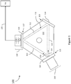
- FIG. 1 is a simplified block diagram illustrating a mirror stack end pumped laser gyroscope 100 of one embodiment of the present disclosure.
- Gyroscope 100 includes a ring laser gyroscope a laser block sensor 110 in which in which interior cavity ring 112 is formed.
- ring refers to a closed path that encloses an area and is not limited to circular closed paths.
- Mirror assemblies 114, 116 and 118 are provided at corners 115, 117 and 119.
- interior cavity ring 112 forms a laser beam path enclosing an area within the laser block sensor 110.
- the interior cavity ring 112 may be empty (for example, at some level of vacuum) or filled with an inert gas.
- light beams 120 of a specific wavelength are created in the interior cavity ring 112 by mirror assembly 114, which comprises an end pumped laser mirror stack assembly 160 described in greater detail below.
- laser block sensor 110 is triangular in shape having three sides and three blunted corners. It should be understood that this is provided as a nonlimiting example, as other embodiment may comprising a laser block sensor 110 formed using a different shape laser block sensor.
- One or more light beams 120 created in the interior cavity ring 112 are repeatedly reflected around the interior cavity ring 112 by the mirror assemblies 114, 116 and 118 (either in the clockwise (CW) direction, counterclockwise (CCW) direction, or both) supporting gain to create lasing of the light beams 120 into laser light.
- one of the other mirror assemblies (such as mirror assembly 116, for example) is used as a read-out device 130.
- the interior cavity ring 112 and the mirror assemblies 114, 116 and 118 thus form a closed laser resonator path.
- the interior resonator cavity of laser block sensor 110 may instead comprise a linear resonator.
- the performance of ring laser gyroscope 100 is observed by coupling optical energy information from the interior cavity ring 112 to the read-out device 130
- the readout device 130 inputs the optical energy and as a function of that optical energy provides an output of one or more voltage signals 132 to one or more processing elements 134.
- the readout device 130 may comprise photodetectors. For example in some embodiments, differences in frequencies between counter-rotating laser beams within the interior cavity ring 112 may be determined from the voltage signals 132, and hence rotation information may be obtained. In addition to the rotation information, the readout device 130 may also provide a voltage signal correlated with laser intensity.
- Figure 1 illustrates a simplified block diagram that provides sufficient detail to facilitate an enabled written description of embodiments of the present invention. Additional details not shown regarding the physical structure and electronic circuitry associated with a laser block sensor for a ring laser gyroscope are considered within the knowledge and skill of one of ordinary skill in the art and are therefore not discussed herein.
- Figure 2 is a block diagram illustrating an end pumped laser mirror stack assembly 200, which may be used as the end pumped laser mirror stack assembly 160 in conjunction with mirror stack end pumped laser gyroscope 100, or used for other applications.
- End pumped laser mirror stack assembly 200 comprises a multilayer thin-film mirror stack 210 deposited on a transparent substrate 205, a pump light injection layer 220 applied to the transparent substrate 205, and a fluorescing lasing material layer 230 (which may be applied to the multilayer thin-film mirror stack 210 or otherwise secured to the substrate 205).
- the path of a laser block sensor interior resonator cavity may be defined by the highly reflective multi-layer dielectric stacks (i.e., reflective at ⁇ 2) shown as mirror assemblies 114, 116 and 118 in Figure 1 .
- the multilayer thin-film mirror stack 210 shown in Figures 2- 5 may serve the function of the mirror assembly 114.
- Pump light injection layer 220 is configured to transmit a beam of light of a first wavelength, ⁇ 1 , (shown in Figure 2 as pump light 222) into a first surface of the substrate 205.
- Transparent substrate 205 is transparent in the sense that it passes light at least in a range of wavelengths that includes ⁇ 1 , through to the opposing second surface of substrate 205.
- one or both surfaces of the transparent substrate 205 are coated with an anti-reflective coating 206 having optical characteristics that include very low reflectance at wavelengths of ⁇ 1 .
- an anti-reflective coating is a coating that has a reflectance of less than 1% for a specified wavelength. Anti-reflective coating(s) 206 thus may be included to reduce optical power loss due to reflections of pump light 222 at the surfaces of substrate 205.
- pump light 222 is generated by one or more light generating optical emitters 221 embedded within the pump light injection layer 220.
- the optical emitters 221 may comprise one or more light emitting diodes (LEDs), an array of LEDs, one or more lasers or array of lasers such as vertical-cavity surface-emitting laser (VCSEL) lasers, edge emitting lasers, or one or more light-emitting coatings.
- the pump light injection layer 220 may comprise an embedded or integrated multi-chip module with components on a carrier that is integrated within the pump light injection layer 220.
- pump light 222 of wavelength ⁇ 1 is generated within the pump light injection layer 220 and directed to the lasing material layer 230.
- the lasing material layer 230 is doped with a dopant (for example, lasing material layer 230 may comprise a layer of Nd-doped silica) that generates a fluorescent light 232 at a second frequency, ⁇ 2 , when exposed to the pump light 222 of wavelength ⁇ 1 .
- the pump light 222 generated by the pump light injection layer 220 has a wavelength ⁇ 1 of approximately 803nm, which causes an Nd doped lasing material layer 230 to fluoresce an output of florescent light 232 having a wavelength ⁇ 2 of approximately 1050-1065nm.
- the end pumped laser mirror stack assembly 200 outputs the fluorescent light 232 through its output end 212, which may be directed, for example, into the interior cavity ring 112 of the mirror stack end pumped laser gyroscope 100.
- the multilayer thin-film mirror stack 210 has a surface reflectivity that is highly reflective to any incoming light entering from output end 212 having a wavelength ⁇ 2 .
- a surface or coating that is highly reflective has a reflectance of at least 99% for a specified wavelength.
- multilayer thin-film mirror stack 210 may comprises a dielectric mirror of alternating coatings of thin film dielectric layers having different refractivity characteristics that are selected to produce the highly reflective surface to light of wavelength ⁇ 2 .
- the refractivity characteristics of the dielectric layers may be tuned to optimize the reflectivity of light received at angle of incidence that would correspond to light expected to be received from the interior cavity ring 112.
- the multilayer thin-film mirror stack 210 may at the same time be highly transmissive to light of wavelength ⁇ 1 so that the pump light 222 will pass through the multilayer thin-film mirror stack 210 to reach the lasing material layer 230 with little loss.
- the stack 200 includes an additional optical coating 240 applied to the output side of lasing material layer 230 that may be anti-reflective to light of wavelength ⁇ 2 , highly-reflective to light of wavelength ⁇ 1 , or both.
- wavelength ⁇ 1 reflection of any pump light 222 emerging from lasing material layer 230 back into the lasing material layer 230 enables multi passes of the pump light 222 through the lasing material which increases efficiency by permitting additional fluorescent light 232 to be produced from the pump light 222 already generated by pump light injection layer 220.
- wavelength ⁇ 2 having an optical coating layer with anti-reflective characteristics for light of wavelength ⁇ 2 reduce loss of efficiency caused by fluorescent light 232 failing to exit the end pumped laser mirror stack assembly 200 at output end 212, and also prevents losses due to scattering by ensuring that any laser light at ⁇ 2 received in from output end 212 passes completely to the multilayer thin-film mirror stack 210 before being reflected.
- the fluorescent light 232 can exit from the end pumped laser mirror stack assembly 200 in alignment with the laser beam path defined within the interior cavity ring 112. That is, in some embodiments, the pump light injection layer 220 aligns the pump light 222 to produce fluorescent light 232 from the lasing material layer 230 that is aligned with the axis (that is, the plane) of the laser beam paths defined within the interior cavity ring 112.
- FIG 3 is a diagram illustrating an alternate implementation of the end pumped laser mirror stack assembly 200 shown in Figure 2 , where the pump light injection layer 220 may include or be further coupled to a layer of optional diffractive optical elements 310. Redirection of the pump light 222 by the diffractive optical elements 310 may be used to control the alignment of fluorescent light 232 generated by lasing material layer 230, for example, to align the fluorescent light 232 output with the laser beam path of interior cavity ring 112, direct the fluorescent light 232 to travel in the CW or CCW directions around the interior cavity ring 112, or split the fluorescent light 232 output so that one portion of the fluorescent light 232 is directed to travel in the CW direction around the interior cavity ring 112 and a second portion of the fluorescent light 232 is directed to travel in the CCW direction around the interior cavity ring 112.
- pump light 222 from selected emitters 221 may be specifically directed to produce fluorescent light 232 having differing alignments from others.
- Nd doped silica has been discussed above as an example lasing material for the lasing material layer 230, it should be understood that this material is mentioned for example purposes only, and that other solid or thin film lasing materials (for example, other rare-earth materials) may be used instead in silica, titania, or other glassy hosts (such as but not limited to oxide glasses, fluoride glasses, fluorosilicate glasses) for any of the embodiments described herein. It should also be understood that although the lasing material layer 230 is illustrated as a distinct layer, in other embodiments, lasing materials may be included, for example, within layers of the mirror stack or substrate 105,
- FIG 4 is a diagram illustrating another alternate implementation of the end pumped laser mirror stack assembly 200 shown in Figure 2 , where the pump light injection layer 220 may further include a piezoelectric driver 410 (or motor) positioned between the multilayer thin-film mirror stack 210 and substrate 205 such that the multilayer thin-film mirror stack 210 is coupled to the substrate 205 via the piezoelectric driver 410.
- piezoelectric driver 410 mechanically dithers (i.e. oscillates) the multilayer thin-film mirror stack 210.
- the pump light 222 may be directed to avoid traversing through the multilayer thin-film mirror stack 210 in its path to lasing material layer 230.
- the multilayer thin-film mirror stack 210 is shaped and/or sized so that pump light 222 can be directed to the lasing material layer 230 while avoiding the multilayer thin-film mirror stack 210.
- the pump light 222 can be directed to the lasing via a waveguide and/or waveguide layers.
- the multilayer thin-film mirror stack 210 has a smaller diameter as compared to the array of optical emitters 221 in the pump light injection layer 220.
- the optional optical elements 310 may be used to also (or instead) diffract the pump light 222 so as to bypass the multilayer thin-film mirror stack 210.
- pump light 222 By directing pump light 222 to avoid passing through a dithering multilayer thin-film mirror stack 210, such an embodiment can increase the optical power of pump light 222 reaching lasing material layers 230.
- such an embodiment provides optical separation such that the newly generated fluorescent light 232 output remains aligned to the laser beam path of the interior cavity ring 112, while separately providing for a dithering induced modulation of laser light travelling around interior cavity ring 112.
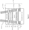
- FIG. 5 is a diagram illustrating another alternate implementation of the end pumped laser mirror stack assembly 500.
- End pumped laser mirror stack assembly 500 functions in the same manner as the various embodiments and implementations of pump light injection layer 220 shown in Figures 2-4 , however, the pump light injection layer 220 comprises one or more remotely located optical emitters 521 that generates the pump light 222, and the pump light 222 is transmitted to the substrate 205 via a fiber optic medium 515 and optical coupling element 510.
- pump light 222 from the one or more remotely located optical emitters 521 is coupled onto the fiber optic medium 515 by a fiber interface 520.
- the fiber interface 520 may comprise an optical combiner that combines the pump light 222 from each of the optical emitters 521 onto either a single fiber optic medium 515, or a multi-fiber optic medium 515.
- the optical coupling element 510 may comprise a flat-end gradient-index optics lens (such as a, SELFOC Microlens, for example) or other diffractive optical elements (such as the Diffractive Optical Elements 310 described above) that couple the pump light 222 from the fiber optic medium 515 into the substrate 205 with the desired beam alignment(s).
Landscapes
- Physics & Mathematics (AREA)
- Electromagnetism (AREA)
- Engineering & Computer Science (AREA)
- Optics & Photonics (AREA)
- Plasma & Fusion (AREA)
- General Physics & Mathematics (AREA)
- Power Engineering (AREA)
- Radar, Positioning & Navigation (AREA)
- Remote Sensing (AREA)
- Chemical & Material Sciences (AREA)
- Crystallography & Structural Chemistry (AREA)
- Gyroscopes (AREA)
- Lasers (AREA)
Applications Claiming Priority (1)
| Application Number | Priority Date | Filing Date | Title |
|---|---|---|---|
| US16/104,773 US20200059062A1 (en) | 2018-08-17 | 2018-08-17 | Systems and methods for end pumped laser mirror stack assemblies |
Publications (1)
| Publication Number | Publication Date |
|---|---|
| EP3633317A2 true EP3633317A2 (de) | 2020-04-08 |
Family
ID=67658733
Family Applications (1)
| Application Number | Title | Priority Date | Filing Date |
|---|---|---|---|
| EP19191607.1A Withdrawn EP3633317A2 (de) | 2018-08-17 | 2019-08-13 | Systeme und verfahren für endgepumpte laserspiegelstapelanordnungen |
Country Status (3)
| Country | Link |
|---|---|
| US (1) | US20200059062A1 (de) |
| EP (1) | EP3633317A2 (de) |
| CN (1) | CN110838672A (de) |
Families Citing this family (3)
| Publication number | Priority date | Publication date | Assignee | Title |
|---|---|---|---|---|
| US10739137B2 (en) | 2018-08-17 | 2020-08-11 | Honeywell International Inc. | Solid state ring laser gyroscope using rare-earth gain dopants in glassy hosts |
| US11476633B2 (en) | 2020-07-20 | 2022-10-18 | Honeywell International Inc. | Apparatus and methods for stable bidirectional output from ring laser gyroscope |
| US11962118B2 (en) | 2020-10-27 | 2024-04-16 | Honeywell International Inc. | Ultraviolet filter for ring laser gyroscope mirrors |
Family Cites Families (4)
| Publication number | Priority date | Publication date | Assignee | Title |
|---|---|---|---|---|
| WO2001078204A1 (en) * | 2000-04-07 | 2001-10-18 | The Government Of The United States Of America, As Represented By The Secretary Of The Navy | Optical pumping injection cavity for optically pumped devices |
| US7590160B2 (en) * | 2004-11-26 | 2009-09-15 | Manni Jeffrey G | High-gain diode-pumped laser amplifier |
| US20190245319A1 (en) * | 2016-05-26 | 2019-08-08 | Compound Photonics Limited | Solid-state laser system |
| US10148059B2 (en) * | 2016-06-23 | 2018-12-04 | Theodore John Podgorski | Gain mirror for solid state ring laser rotation sensors |
-
2018
- 2018-08-17 US US16/104,773 patent/US20200059062A1/en not_active Abandoned
-
2019
- 2019-07-23 CN CN201910665993.7A patent/CN110838672A/zh active Pending
- 2019-08-13 EP EP19191607.1A patent/EP3633317A2/de not_active Withdrawn
Also Published As
| Publication number | Publication date |
|---|---|
| US20200059062A1 (en) | 2020-02-20 |
| CN110838672A (zh) | 2020-02-25 |
Similar Documents
| Publication | Publication Date | Title |
|---|---|---|
| US7409122B2 (en) | End face structure of optical fiber, optical fiber laser, and laser processing apparatus | |
| US11868023B2 (en) | Light-emitting device and optical fiber | |
| EP3633317A2 (de) | Systeme und verfahren für endgepumpte laserspiegelstapelanordnungen | |
| NO843902L (no) | Fiberoptisk forsterker | |
| US20110141758A1 (en) | Optical coupler and active optical module comprising the same | |
| US20090323736A1 (en) | High brightness laser module | |
| US10656510B2 (en) | Superluminescent light emitting diode (SLED) device | |
| WO2006041619A2 (en) | InGaN LED PUMPED II-VI SEMICONDUCTOR LASER | |
| CN116526261A (zh) | 小型化的主振荡器功率放大器结构二极管泵浦固体激光器 | |
| CN107078463B (zh) | Ld模块 | |
| US7439533B2 (en) | Optical module and optical communication device | |
| KR101899059B1 (ko) | 평면 광도파로 및 광 모듈 | |
| US20080273570A1 (en) | Optically Pumped Waveguide Laser With a Tapered Waveguide Section | |
| CN1109387C (zh) | 固体激光器 | |
| JP2005084673A (ja) | 高められた光学的結合効率をもつ光検出器/光ファイバ装置及びこれを形成する方法 | |
| WO2011065148A1 (ja) | レーザ光源装置 | |
| US10907967B1 (en) | Ring laser gyroscopes with active volume Bragg grating | |
| US20070176179A1 (en) | Vertical external cavity surface emitting laser including second harmonic generation crystal having mirror surface | |
| US20260106428A1 (en) | Optically pumped solid-state laser | |
| US20130208349A1 (en) | Laser feedback damage mitigation assembly and apparatus | |
| KR100303831B1 (ko) | 광펌프레이저밸브및광펌프레이저장치 | |
| JP2000164957A (ja) | 固体レーザ装置 | |
| US7099074B2 (en) | Side-pumping laser and optical fiber system | |
| JP2000081546A (ja) | 光モジュール | |
| JP2026002290A (ja) | 投光器、および測定装置 |
Legal Events
| Date | Code | Title | Description |
|---|---|---|---|
| PUAI | Public reference made under article 153(3) epc to a published international application that has entered the european phase |
Free format text: ORIGINAL CODE: 0009012 |
|
| AK | Designated contracting states |
Kind code of ref document: A2 Designated state(s): AL AT BE BG CH CY CZ DE DK EE ES FI FR GB GR HR HU IE IS IT LI LT LU LV MC MK MT NL NO PL PT RO RS SE SI SK SM TR |
|
| AX | Request for extension of the european patent |
Extension state: BA ME |
|
| STAA | Information on the status of an ep patent application or granted ep patent |
Free format text: STATUS: THE APPLICATION HAS BEEN WITHDRAWN |
|
| 18W | Application withdrawn |
Effective date: 20200701 |
|
| P01 | Opt-out of the competence of the unified patent court (upc) registered |
Effective date: 20230525 |