EP3633396A1 - Verfahren zum greifen einer elektrischen übertragungsleitung zur fernüberwachung - Google Patents
Verfahren zum greifen einer elektrischen übertragungsleitung zur fernüberwachung Download PDFInfo
- Publication number
- EP3633396A1 EP3633396A1 EP19753734.3A EP19753734A EP3633396A1 EP 3633396 A1 EP3633396 A1 EP 3633396A1 EP 19753734 A EP19753734 A EP 19753734A EP 3633396 A1 EP3633396 A1 EP 3633396A1
- Authority
- EP
- European Patent Office
- Prior art keywords
- flying
- execution unit
- lifting
- lifting facility
- magnetic head
- Prior art date
- Legal status (The legal status is an assumption and is not a legal conclusion. Google has not performed a legal analysis and makes no representation as to the accuracy of the status listed.)
- Withdrawn
Links
- 238000012544 monitoring process Methods 0.000 title claims abstract description 12
- 230000005540 biological transmission Effects 0.000 title claims abstract description 9
- 238000000034 method Methods 0.000 title claims abstract description 7
- 230000033001 locomotion Effects 0.000 claims abstract description 8
- 239000004020 conductor Substances 0.000 claims abstract 4
- 230000008439 repair process Effects 0.000 abstract description 3
- 230000009471 action Effects 0.000 description 4
- 230000008859 change Effects 0.000 description 2
- 230000002452 interceptive effect Effects 0.000 description 1
- 230000007774 longterm Effects 0.000 description 1
- 230000008569 process Effects 0.000 description 1
- 230000005855 radiation Effects 0.000 description 1
- 230000002285 radioactive effect Effects 0.000 description 1
- 230000000284 resting effect Effects 0.000 description 1
- 238000005096 rolling process Methods 0.000 description 1
Images

Classifications
-
- G—PHYSICS
- G01—MEASURING; TESTING
- G01R—MEASURING ELECTRIC VARIABLES; MEASURING MAGNETIC VARIABLES
- G01R31/00—Arrangements for testing electric properties; Arrangements for locating electric faults; Arrangements for electrical testing characterised by what is being tested not provided for elsewhere
- G01R31/08—Locating faults in cables, transmission lines, or networks
-
- G—PHYSICS
- G01—MEASURING; TESTING
- G01R—MEASURING ELECTRIC VARIABLES; MEASURING MAGNETIC VARIABLES
- G01R31/00—Arrangements for testing electric properties; Arrangements for locating electric faults; Arrangements for electrical testing characterised by what is being tested not provided for elsewhere
- G01R31/08—Locating faults in cables, transmission lines, or networks
- G01R31/081—Locating faults in cables, transmission lines, or networks according to type of conductors
- G01R31/085—Locating faults in cables, transmission lines, or networks according to type of conductors in power transmission or distribution lines, e.g. overhead
-
- B—PERFORMING OPERATIONS; TRANSPORTING
- B64—AIRCRAFT; AVIATION; COSMONAUTICS
- B64U—UNMANNED AERIAL VEHICLES [UAV]; EQUIPMENT THEREFOR
- B64U10/00—Type of UAV
- B64U10/10—Rotorcrafts
- B64U10/13—Flying platforms
-
- B—PERFORMING OPERATIONS; TRANSPORTING
- B64—AIRCRAFT; AVIATION; COSMONAUTICS
- B64U—UNMANNED AERIAL VEHICLES [UAV]; EQUIPMENT THEREFOR
- B64U2101/00—UAVs specially adapted for particular uses or applications
- B64U2101/25—UAVs specially adapted for particular uses or applications for manufacturing or servicing
- B64U2101/26—UAVs specially adapted for particular uses or applications for manufacturing or servicing for manufacturing, inspections or repairs
-
- B—PERFORMING OPERATIONS; TRANSPORTING
- B64—AIRCRAFT; AVIATION; COSMONAUTICS
- B64U—UNMANNED AERIAL VEHICLES [UAV]; EQUIPMENT THEREFOR
- B64U30/00—Means for producing lift; Empennages; Arrangements thereof
- B64U30/20—Rotors; Rotor supports
Definitions
- the invention relates to aircraft engineering and, in particular, to helicopter-type unmanned aircrafts included in robotic and remote controlled complexes designed for performing various kinds of operation in difficult-to-access or health-dangerous conditions, for example, for monitoring state of or conducting repair work on power transmission lines, in places with high background of radioactive emissions, etc.
- a flying-lifting facility more precisely, the motors of the flying-lifting facility are used only for moving in space with change of movement height, direction and speed.
- the movement in space may only be performed from point A to point B (conveying of load) [1], or with execution of any actions during the flight associated with change of flight altitude, speed and direction, for example, for video surveillance and radiation survey of a territory [2].
- the movement control may be either software, interactive, or manual (with push-buttons) and performed from a control panel.
- the flying-lifting facility performs required actions associated with specific task.
- the flying-lifting facility and the execution unit are connected to each other and are integral, and the execution unit comprises all operating members required for performing the task, including power drives for these members.
- An example of such devices may be a device for diagnostic of overhead power transmission lines (OPTL) [3].
- the flying-lifting facility carries the execution unit to a worksite (on the lightning-protective wire of the OPTL) and settles it on the wire.
- execution unit performs its task related to monitoring process of state of the wire by moving from one tower of the OPLT to another. After that, the flying-lifting device takes off and transfers the execution unit over the tower to monitor a next wire, etc.
- the operating member performing the monitor and diagnostic operation in the execution unit of the device for diagnostics of the overhead power transmission line may be, for example, a magnetic head of a magnetic flaw detector which, when settled on the wire, has to open and then to close, for performing the monitoring, by embracing the wire. Then, moving along the wire to the next tower, it has to monitor state of the wire. At the end of the monitoring, the head has to open, so that the flying-lifting facility is able to remove the execution unit from the wire and transfer it to other side of the tower.
- the magnetic head In order the magnetic head be opened and closed, it is typically equipped with a special electric drive.
- the presence of the electric drive for opening-closing the magnetic head not only complicates a design of the device as a whole, but also increases probability of failure during its operation.
- the flying-lifting facility In case of failure of electric drive with the closed magnetic head, the flying-lifting facility would not be able to remove the execution unit from the wire. In such a case, it would be necessary to carry out rather labor intensive and long-term operations including necessary disabling the OPTL to open or repair the opening drive at the height of the magnetic head to remove the entire device from the wire.
- Object of the present invention is to simplify the design, increase reliability and safety of operation of robotic and remote-controlled complexes including helicopter-type flying-lifting facilities.
- the above object is achieved by that in order to actuate the operating members of the execution units, the propelling force of the motors or the gravitational force of the flying-lifting facility which occur at takeoff or landing, respectively, are used.
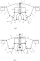
- the apparatus consists of a flying-lifting facility with motors 1 mounted on a frame 2 provided with a sleeve 3.
- the sleeve 3 is movably seated on a guide 4 mounted on an execution unit 5.
- Axis of the sleeve coincides with a vertical line passing through the center of mass of the execution unit.
- Adjustable upper and lower stop members are installed at the top and at the base of the guide 4, respectively.
- the execution unit 5 is provided with an operating member 8 - a magnetic head of a magnetic flaw detector, the head made as a cylinder (yoke) consisting of two half-cylinders interconnected by an axle 9.
- the half-cylinders of the magnetic head are connected by means of rods 10 and bell-crank levers 11 to the frame 2 of the flying-lifting facility.
- execution unit 5 is provided with supports 12 and wheeled transportation facility 13 for moving it along a wire 14.
- the execution unit 5 stands “on earth” ( FIG. 1 ) by resting on the supports 12.
- the sleeve 3 together with the frame 2 of the flying-lifting facility under the action of gravitational force are in the lower position at the adjustable stop member 7.
- the yoke of the magnetic head 8 (operating member) is in the closed position.
- the opened magnetic head 8 While landing on the wire 14 ( FIG. 4 ), the opened magnetic head 8 is moved downward, the wire enters the head until the wire abuts against the head upper part with a narrow opening (less than the diameter of the wire).
- the wheels of the transportation facility 13 rest on the wire 14, the execution unit 5 stops to move down and the flying-lifting facility continues to move down under the action of gravitational force, the magnetic head is being closed (rolling forces of the half-cylinders), and the sleeve 3 reaches the lower stop member 7.
- the execution unit 5 is ready to perform monitoring of the wire 14. Upon completion of the monitoring performed by moving the magnetic head 8 along the entire length of the wire 14 by wheeled transportation facility 13, the motors of the flying-lifting facility are powered on.
- the flying-lifting facility starts to rise (the sleeve 3 slides along the guide 4), and rods 10 and levers 11 open the magnetic head 8.
- the sleeve 3 abuts against the upper adjustable stop member 6 and lifting of the execution unit 5 is started for repositioning it into a new worksite.
- the apparatus may be easily removed from the lightning-protection wire by lifting it upwards by the frame 2 of the flying-lifting facility.
- the lifting force of the motors of the flying-lifting facility at takeoff is used, and when landing in order to close the execution member, the gravitational force the facility is used, which influences the operating member by means of movement of the flying-lifting facility and execution unit relative to each other.
Landscapes
- Engineering & Computer Science (AREA)
- Physics & Mathematics (AREA)
- General Physics & Mathematics (AREA)
- Aviation & Aerospace Engineering (AREA)
- Mechanical Engineering (AREA)
- Remote Sensing (AREA)
- Investigating Or Analyzing Materials By The Use Of Magnetic Means (AREA)
- Electric Cable Installation (AREA)
- Manipulator (AREA)
Applications Claiming Priority (2)
| Application Number | Priority Date | Filing Date | Title |
|---|---|---|---|
| RU2018106097A RU2683417C1 (ru) | 2018-02-19 | 2018-02-19 | Способ захвата провода линии электропередач рабочим органом исполнительного блока устройства для дистанционного контроля, оснащенного для его доставки к месту работы летно-подъемным средством, и устройство для его осуществления |
| PCT/RU2019/050015 WO2019160453A1 (ru) | 2018-02-19 | 2019-02-09 | Способ захвата линии электропередач для дистанционного контроля |
Publications (2)
| Publication Number | Publication Date |
|---|---|
| EP3633396A1 true EP3633396A1 (de) | 2020-04-08 |
| EP3633396A4 EP3633396A4 (de) | 2021-03-17 |
Family
ID=66089658
Family Applications (1)
| Application Number | Title | Priority Date | Filing Date |
|---|---|---|---|
| EP19753734.3A Withdrawn EP3633396A4 (de) | 2018-02-19 | 2019-02-09 | Verfahren zum greifen einer elektrischen übertragungsleitung zur fernüberwachung |
Country Status (6)
| Country | Link |
|---|---|
| US (1) | US20210123965A1 (de) |
| EP (1) | EP3633396A4 (de) |
| CN (1) | CN110799847A (de) |
| CA (1) | CA3068217A1 (de) |
| RU (1) | RU2683417C1 (de) |
| WO (1) | WO2019160453A1 (de) |
Cited By (2)
| Publication number | Priority date | Publication date | Assignee | Title |
|---|---|---|---|---|
| US11368002B2 (en) | 2016-11-22 | 2022-06-21 | Hydro-Quebec | Unmanned aerial vehicle for monitoring an electrical line |
| US12097956B2 (en) | 2021-04-30 | 2024-09-24 | Hydro-Quebec | Drone with tool positioning system |
Families Citing this family (3)
| Publication number | Priority date | Publication date | Assignee | Title |
|---|---|---|---|---|
| RU197328U1 (ru) * | 2019-09-05 | 2020-04-21 | Открытое Акционерное Общество "Межрегиональная Распределительная Сетевая Компания Урала" (Оао "Мрск Урала") | Устройство для дистанционного магнитного сканирования металлического каната |
| RU2731846C1 (ru) * | 2020-02-21 | 2020-09-08 | Сергей Григорьевич Кузовников | Устройство для диагностики воздушных линий электропередач |
| WO2023132758A1 (ru) * | 2022-01-10 | 2023-07-13 | Общество с ограниченной ответственностью "Лаборатория будущего" | Способ смазки троса или провода воздушной линии электропередачи |
Family Cites Families (17)
| Publication number | Priority date | Publication date | Assignee | Title |
|---|---|---|---|---|
| RU2223803C1 (ru) | 2002-10-25 | 2004-02-20 | Кирюшин Игорь Герольдович | Способ обнаружения потерпевшего и точной доставки полезного груза для него при проведении поисково-спасательных операций |
| GB0311138D0 (en) * | 2003-05-15 | 2003-06-18 | Univ Wales Bangor | Improvements in or relating to diagnostics |
| RU2390468C2 (ru) | 2007-12-25 | 2010-05-27 | Юрий Георгиевич Данилин | Способ экстренной доставки на изолированный объект полезного груза |
| CN102317040A (zh) * | 2010-02-10 | 2012-01-11 | 电力研究所有限公司 | 线路巡检机器人和系统 |
| RU2421746C1 (ru) * | 2010-02-10 | 2011-06-20 | Ооо Научно-Производственное Предприятие "Энергоконсалт" | Способ диагностики высоковольтной линии электропередачи |
| CN102412530B (zh) * | 2011-12-23 | 2014-04-09 | 北京国网富达科技发展有限责任公司 | 线航两栖电力线路综合维护机器人的线路维护方法 |
| CN105263800A (zh) * | 2013-08-23 | 2016-01-20 | 国防科技研究院(公共组织) | 一种具有双偏航控制系统的垂直起降无人机 |
| RU2558002C1 (ru) * | 2014-02-03 | 2015-07-27 | Общество с ограниченной ответственностью "Лаборатория будущего" | Устройство диагностики воздушных линий электропередач и его компонент |
| US9932110B2 (en) * | 2014-07-22 | 2018-04-03 | Jonathan McNally | Method for installing an object using an unmanned aerial vehicle |
| CN104384118B (zh) * | 2014-09-16 | 2016-08-24 | 国家电网公司 | 带电清除异物机械臂手 |
| WO2016103264A1 (en) * | 2014-12-24 | 2016-06-30 | Noam Cohen | A method and apparatus for extending range of small unmanned aerial vehicles - multicopters |
| US9878787B2 (en) * | 2015-07-15 | 2018-01-30 | Elwha Llc | System and method for operating unmanned aircraft |
| KR20170078434A (ko) * | 2015-12-29 | 2017-07-07 | 주식회사 페라리스파워 | 전력선 충전 방식 무인 비행 장치 및 충전 방법 |
| CN106992469B (zh) * | 2017-05-31 | 2018-08-14 | 长沙理工大学 | 一种输电线路带电作业机器人及其上、下线控制方法 |
| KR101815091B1 (ko) * | 2017-06-13 | 2018-01-04 | 강종수 | 고압선 점검용 무인비행체 및 그 제어방법 |
| CN107380415B (zh) * | 2017-06-21 | 2019-06-18 | 浙江大学宁波理工学院 | 一种电力线巡检用的飞行器 |
| CN107458617A (zh) * | 2017-08-31 | 2017-12-12 | 四川省冶地工程勘察设计有限公司 | 一种无人机测绘数据采集装置 |
-
2018
- 2018-02-19 RU RU2018106097A patent/RU2683417C1/ru active
-
2019
- 2019-02-09 CA CA3068217A patent/CA3068217A1/en not_active Abandoned
- 2019-02-09 WO PCT/RU2019/050015 patent/WO2019160453A1/ru not_active Ceased
- 2019-02-09 US US16/625,481 patent/US20210123965A1/en not_active Abandoned
- 2019-02-09 CN CN201980003224.9A patent/CN110799847A/zh active Pending
- 2019-02-09 EP EP19753734.3A patent/EP3633396A4/de not_active Withdrawn
Cited By (2)
| Publication number | Priority date | Publication date | Assignee | Title |
|---|---|---|---|---|
| US11368002B2 (en) | 2016-11-22 | 2022-06-21 | Hydro-Quebec | Unmanned aerial vehicle for monitoring an electrical line |
| US12097956B2 (en) | 2021-04-30 | 2024-09-24 | Hydro-Quebec | Drone with tool positioning system |
Also Published As
| Publication number | Publication date |
|---|---|
| CN110799847A (zh) | 2020-02-14 |
| US20210123965A1 (en) | 2021-04-29 |
| WO2019160453A1 (ru) | 2019-08-22 |
| EP3633396A4 (de) | 2021-03-17 |
| CA3068217A1 (en) | 2019-08-22 |
| RU2683417C1 (ru) | 2019-03-28 |
Similar Documents
| Publication | Publication Date | Title |
|---|---|---|
| EP3633396A1 (de) | Verfahren zum greifen einer elektrischen übertragungsleitung zur fernüberwachung | |
| EP3104184A1 (de) | Verfahren und vorrichtung zur lokalisierung von fehlern bei freileitungen | |
| CN104386250B (zh) | 一种多旋翼巡检飞行器及输电线路巡检系统 | |
| EP4343992A2 (de) | Unbemanntes luftfahrzeug zur überwachung einer elektrischen leitung | |
| KR102178393B1 (ko) | 무인 항공기를 이용한 송전선로 감시 장치 | |
| CN204355272U (zh) | 一种多旋翼巡检飞行器及输电线路巡检系统 | |
| EP3253705B1 (de) | Transportsystem mit einem unbemannten luftfahrzeug und einer greifvorrichtung zur aufnahme von stückgütern von oben, und verfahren zur aufnahme von stückgütern unter verwendung dieses transportsystems | |
| RU2717136C1 (ru) | Устройство для диагностики воздушных линий электропередач | |
| US20210268640A1 (en) | Method and system for installing bird flight diverters | |
| DE102009015648A1 (de) | Anordnung zur Durchführung von Wartungsarbeiten an Flugzeugen | |
| EP3377701B1 (de) | Verfahren und vorrichtung zum absichern einer bewegung eines kraftfahrzeugs auf einer schrägen rampe | |
| CN114367487A (zh) | 无人机高压带电水冲洗系统、方法及存储介质 | |
| CN110165602B (zh) | 一种高压架线用系统及方法 | |
| EP3071372A1 (de) | Arbeitsvorrichtung und arbeitsverfahren | |
| Wang et al. | Active translatory drive system with docking capability for uav power line inspection | |
| DE102020214021A1 (de) | Verfahren zum Betrieb eines Kransystems und Kransystem | |
| DE102016201159A1 (de) | Automatisierte Inspektion von Infrastrukturelementen | |
| RU2731846C1 (ru) | Устройство для диагностики воздушных линий электропередач | |
| Espinosa Peralta et al. | ROSE: robot for automatic spacer installation in overhead power lines | |
| CN113335543B (zh) | 一种基于无人机飞行中的在线监测电站设备 | |
| EP3887098B1 (de) | Roboteranordnung mit einem auftriebskörper zur befüllung mit einem gas leichter als luft | |
| GB1598220A (en) | Automatic coke oven machinery positioning system | |
| Scaff et al. | Automatic elevator for assisting maintenance of distribution power line-Control system | |
| JPS62236694A (ja) | 移動ロボツトシステム | |
| Herrerías et al. | ROSE: Robot for Automatic Spacer Installation in Overhead Power Lines |
Legal Events
| Date | Code | Title | Description |
|---|---|---|---|
| STAA | Information on the status of an ep patent application or granted ep patent |
Free format text: STATUS: THE INTERNATIONAL PUBLICATION HAS BEEN MADE |
|
| PUAI | Public reference made under article 153(3) epc to a published international application that has entered the european phase |
Free format text: ORIGINAL CODE: 0009012 |
|
| STAA | Information on the status of an ep patent application or granted ep patent |
Free format text: STATUS: REQUEST FOR EXAMINATION WAS MADE |
|
| 17P | Request for examination filed |
Effective date: 20191231 |
|
| AK | Designated contracting states |
Kind code of ref document: A1 Designated state(s): AL AT BE BG CH CY CZ DE DK EE ES FI FR GB GR HR HU IE IS IT LI LT LU LV MC MK MT NL NO PL PT RO RS SE SI SK SM TR |
|
| AX | Request for extension of the european patent |
Extension state: BA ME |
|
| A4 | Supplementary search report drawn up and despatched |
Effective date: 20210215 |
|
| RIC1 | Information provided on ipc code assigned before grant |
Ipc: B64C 39/02 20060101ALI20210209BHEP Ipc: G01R 31/08 20200101AFI20210209BHEP |
|
| DAV | Request for validation of the european patent (deleted) | ||
| DAX | Request for extension of the european patent (deleted) | ||
| STAA | Information on the status of an ep patent application or granted ep patent |
Free format text: STATUS: THE APPLICATION IS DEEMED TO BE WITHDRAWN |
|
| 18D | Application deemed to be withdrawn |
Effective date: 20210901 |