EP3633488B1 - Dispositif électronique comprenant un accessoire - Google Patents
Dispositif électronique comprenant un accessoire Download PDFInfo
- Publication number
- EP3633488B1 EP3633488B1 EP18805704.6A EP18805704A EP3633488B1 EP 3633488 B1 EP3633488 B1 EP 3633488B1 EP 18805704 A EP18805704 A EP 18805704A EP 3633488 B1 EP3633488 B1 EP 3633488B1
- Authority
- EP
- European Patent Office
- Prior art keywords
- electronic device
- cover part
- magnet
- face
- curved face
- Prior art date
- Legal status (The legal status is an assumption and is not a legal conclusion. Google has not performed a legal analysis and makes no representation as to the accuracy of the status listed.)
- Active
Links
Images






Classifications
-
- G—PHYSICS
- G06—COMPUTING OR CALCULATING; COUNTING
- G06F—ELECTRIC DIGITAL DATA PROCESSING
- G06F1/00—Details not covered by groups G06F3/00 - G06F13/00 and G06F21/00
- G06F1/16—Constructional details or arrangements
- G06F1/1613—Constructional details or arrangements for portable computers
- G06F1/1633—Constructional details or arrangements of portable computers not specific to the type of enclosures covered by groups G06F1/1615 - G06F1/1626
- G06F1/1675—Miscellaneous details related to the relative movement between the different enclosures or enclosure parts
- G06F1/1679—Miscellaneous details related to the relative movement between the different enclosures or enclosure parts for locking or maintaining the movable parts of the enclosure in a fixed position, e.g. latching mechanism at the edge of the display in a laptop or for the screen protective cover of a PDA
-
- G—PHYSICS
- G06—COMPUTING OR CALCULATING; COUNTING
- G06F—ELECTRIC DIGITAL DATA PROCESSING
- G06F1/00—Details not covered by groups G06F3/00 - G06F13/00 and G06F21/00
- G06F1/16—Constructional details or arrangements
- G06F1/1613—Constructional details or arrangements for portable computers
- G06F1/1633—Constructional details or arrangements of portable computers not specific to the type of enclosures covered by groups G06F1/1615 - G06F1/1626
- G06F1/1656—Details related to functional adaptations of the enclosure, e.g. to provide protection against EMI, shock, water, or to host detachable peripherals like a mouse or removable expansions units like PCMCIA cards, or to provide access to internal components for maintenance or to removable storage supports like CDs or DVDs, or to mechanically mount accessories
-
- G—PHYSICS
- G06—COMPUTING OR CALCULATING; COUNTING
- G06F—ELECTRIC DIGITAL DATA PROCESSING
- G06F1/00—Details not covered by groups G06F3/00 - G06F13/00 and G06F21/00
- G06F1/16—Constructional details or arrangements
- G06F1/1613—Constructional details or arrangements for portable computers
- G06F1/1633—Constructional details or arrangements of portable computers not specific to the type of enclosures covered by groups G06F1/1615 - G06F1/1626
- G06F1/1656—Details related to functional adaptations of the enclosure, e.g. to provide protection against EMI, shock, water, or to host detachable peripherals like a mouse or removable expansions units like PCMCIA cards, or to provide access to internal components for maintenance or to removable storage supports like CDs or DVDs, or to mechanically mount accessories
- G06F1/166—Details related to functional adaptations of the enclosure, e.g. to provide protection against EMI, shock, water, or to host detachable peripherals like a mouse or removable expansions units like PCMCIA cards, or to provide access to internal components for maintenance or to removable storage supports like CDs or DVDs, or to mechanically mount accessories related to integrated arrangements for adjusting the position of the main body with respect to the supporting surface, e.g. legs for adjusting the tilt angle
-
- G—PHYSICS
- G06—COMPUTING OR CALCULATING; COUNTING
- G06F—ELECTRIC DIGITAL DATA PROCESSING
- G06F1/00—Details not covered by groups G06F3/00 - G06F13/00 and G06F21/00
- G06F1/16—Constructional details or arrangements
-
- G—PHYSICS
- G06—COMPUTING OR CALCULATING; COUNTING
- G06F—ELECTRIC DIGITAL DATA PROCESSING
- G06F1/00—Details not covered by groups G06F3/00 - G06F13/00 and G06F21/00
- G06F1/16—Constructional details or arrangements
- G06F1/1613—Constructional details or arrangements for portable computers
- G06F1/1628—Enclosures for carrying portable computers with peripheral devices, e.g. cases for a laptop and a printer
-
- G—PHYSICS
- G06—COMPUTING OR CALCULATING; COUNTING
- G06F—ELECTRIC DIGITAL DATA PROCESSING
- G06F1/00—Details not covered by groups G06F3/00 - G06F13/00 and G06F21/00
- G06F1/16—Constructional details or arrangements
- G06F1/1613—Constructional details or arrangements for portable computers
- G06F1/1632—External expansion units, e.g. docking stations
-
- G—PHYSICS
- G06—COMPUTING OR CALCULATING; COUNTING
- G06F—ELECTRIC DIGITAL DATA PROCESSING
- G06F1/00—Details not covered by groups G06F3/00 - G06F13/00 and G06F21/00
- G06F1/16—Constructional details or arrangements
- G06F1/1613—Constructional details or arrangements for portable computers
- G06F1/1633—Constructional details or arrangements of portable computers not specific to the type of enclosures covered by groups G06F1/1615 - G06F1/1626
-
- G—PHYSICS
- G06—COMPUTING OR CALCULATING; COUNTING
- G06F—ELECTRIC DIGITAL DATA PROCESSING
- G06F1/00—Details not covered by groups G06F3/00 - G06F13/00 and G06F21/00
- G06F1/16—Constructional details or arrangements
- G06F1/1613—Constructional details or arrangements for portable computers
- G06F1/1633—Constructional details or arrangements of portable computers not specific to the type of enclosures covered by groups G06F1/1615 - G06F1/1626
- G06F1/1662—Details related to the integrated keyboard
- G06F1/1669—Detachable keyboards
-
- G—PHYSICS
- G06—COMPUTING OR CALCULATING; COUNTING
- G06F—ELECTRIC DIGITAL DATA PROCESSING
- G06F1/00—Details not covered by groups G06F3/00 - G06F13/00 and G06F21/00
- G06F1/16—Constructional details or arrangements
- G06F1/1613—Constructional details or arrangements for portable computers
- G06F1/1633—Constructional details or arrangements of portable computers not specific to the type of enclosures covered by groups G06F1/1615 - G06F1/1626
- G06F1/1675—Miscellaneous details related to the relative movement between the different enclosures or enclosure parts
- G06F1/1681—Details related solely to hinges
-
- H—ELECTRICITY
- H04—ELECTRIC COMMUNICATION TECHNIQUE
- H04B—TRANSMISSION
- H04B5/00—Near-field transmission systems, e.g. inductive or capacitive transmission systems
- H04B5/40—Near-field transmission systems, e.g. inductive or capacitive transmission systems characterised by components specially adapted for near-field transmission
- H04B5/48—Transceivers
-
- H—ELECTRICITY
- H05—ELECTRIC TECHNIQUES NOT OTHERWISE PROVIDED FOR
- H05K—PRINTED CIRCUITS; CASINGS OR CONSTRUCTIONAL DETAILS OF ELECTRIC APPARATUS; MANUFACTURE OF ASSEMBLAGES OF ELECTRICAL COMPONENTS
- H05K5/00—Casings, cabinets or drawers for electric apparatus
- H05K5/02—Details
- H05K5/03—Covers
-
- H—ELECTRICITY
- H05—ELECTRIC TECHNIQUES NOT OTHERWISE PROVIDED FOR
- H05K—PRINTED CIRCUITS; CASINGS OR CONSTRUCTIONAL DETAILS OF ELECTRIC APPARATUS; MANUFACTURE OF ASSEMBLAGES OF ELECTRICAL COMPONENTS
- H05K9/00—Screening of apparatus or components against electric or magnetic fields
- H05K9/0007—Casings
- H05K9/0049—Casings being metallic containers
-
- G—PHYSICS
- G06—COMPUTING OR CALCULATING; COUNTING
- G06F—ELECTRIC DIGITAL DATA PROCESSING
- G06F2200/00—Indexing scheme relating to G06F1/04 - G06F1/32
- G06F2200/16—Indexing scheme relating to G06F1/16 - G06F1/18
- G06F2200/163—Indexing scheme relating to constructional details of the computer
- G06F2200/1633—Protecting arrangement for the entire housing of the computer
Definitions
- the invention relates to an electronic device including an accessory.
- the electronic devices have come to provide various functions such as music and video playback, game, camera, schedule management, and dictionary functions in addition to the original functions thereof in order to meet various needs of users, and further provide a function of adding a variety of data retrieval applications and new applications.
- the electronic devices are reduced in size and weight, so that a user is capable of carrying and using the electronic devices in his/her hand or in his/her pocket or bag while moving.
- the electronic devices are stored and carried as described above.
- the electronic devices are used in the state of being mounted in separate accessories.
- the accessories may provide basic functions of safely storing the electronic device and protecting the electronic devices from external impacts or scratches.
- the connection device may comprise a plurality of connection portions that are physically and communicatively coupled, one to another.
- Each of the plurality of connection portions has at least one communication contact configured to form a communicative coupling with a respective one of a plurality of computing devices and with at least one other communication contact of another one of the connections portions to support communication between the plurality of computing devices.
- An accessory is provided with a mounting portion for coupling or detachably attaching the electronic device thereto, and a cover, which is bent to be used as a cradle, is provided at one end of the mounting portion.
- the accessory is heavy, thick, and voluminous. Further, it is cumbersome to couple or detachably attach the electronic device to the mounting portion.
- Various embodiments of the disclosure may provide an accessory that can be easily attached to/detached from an electronic device, and an electronic including the same.
- Various embodiments of the disclosure may provide an accessory capable of protecting an electronic device having a small thickness and size, and an electronic device including the same.
- an electronic device is provided as defined in claim 1.
- the accessory includes first and second cover parts attached to/detached from first and second electronic devices and rotated in the attached state to allow the electronic devices to be mounted at various angles using magnets.
- the user is able to mount the electronic device at a desired angle.
- the use of the product can be facilitated, the thickness, volume, and weight of the product can be reduced, and the appearance design of the product can be enhanced.
- first, second, the first, or the second may modify various elements regardless of the order and/or the importance, and is used merely to distinguish one element from another element without limiting the corresponding elements.
- element e.g., first element
- second element the element may be connected directly to the another element or connected to the another element through yet another element (e.g., third element).
- the expression “configured to” as used in various embodiments may be interchangeably used with, for example, “suitable for”, “having the capacity to”, “adapted to”, “made to”, “capable of”, or “designed to” in terms of hardware or software, according to circumstances.
- the expression “device configured to” may mean that the device, together with other devices or components, “is able to”.
- processor adapted (or configured) to perform A, B, and C may mean a dedicated processor (e.g., embedded processor) only for performing the corresponding operations or a generic-purpose processor (e.g., Central Processing Unit (CPU) or Application Processor (AP)) that can perform the corresponding operations by executing one or more software programs stored in a memory device.
- processor e.g., embedded processor
- generic-purpose processor e.g., Central Processing Unit (CPU) or Application Processor (AP)
- An electronic device may include at least one of, for example, a smartphone, a tablet personal computer (PC), a mobile phone, a video phone, an electronic book reader (e-book reader), a desktop PC, a laptop PC, a netbook computer, a workstation, a server, a personal digital assistant (PDA), a portable multimedia player (PMP), an MPEG-1 audio layer-3 (MP3) player, a mobile medical device, a camera, or a wearable device.
- a smartphone a tablet personal computer (PC)
- a mobile phone a video phone
- e-book reader electronic book reader
- desktop PC a laptop PC
- netbook computer a netbook computer
- workstation a server
- PDA personal digital assistant
- PMP portable multimedia player
- MP3 MPEG-1 audio layer-3
- the wearable device may include at least one of an accessory type (e.g., a watch, a ring, a bracelet, an anklet, a necklace, a pair of glasses, a contact lens, or a Head-Mounted Device (HMD)), a fabric or clothing integrated type (e.g., an electronic clothing), a body-mounted type (e.g., a skin pad, or tattoo), and a bio-implantable type (e.g., an implantable circuit).
- an accessory type e.g., a watch, a ring, a bracelet, an anklet, a necklace, a pair of glasses, a contact lens, or a Head-Mounted Device (HMD)
- a fabric or clothing integrated type e.g., an electronic clothing
- a body-mounted type e.g., a skin pad, or tattoo
- a bio-implantable type e.g., an implantable circuit
- the electronic device may include at least one of, for example, a television, a Digital Video Disk (DVD) player, an audio player, a refrigerator, an air conditioner, a vacuum cleaner, an oven, a microwave oven, a washing machine, an air cleaner, a set-top box, a home automation control panel, a security control panel, a TV box (e.g., Samsung HomeSync TM , Apple TV TM , or Google TV TM ), a game console (e.g., Xbox TM and PlayStation TM ), an electronic dictionary, an electronic key, a camcorder, and an electronic photo frame.
- DVD Digital Video Disk
- the electronic device may include at least one of various medical devices (e.g., various portable medical measuring devices (a blood glucose monitoring device, a heart rate monitoring device, a blood pressure measuring device, a body temperature measuring device, etc.), a Magnetic Resonance Angiography (MRA), a Magnetic Resonance Imaging (MRI), a Computed Tomography (CT) machine, and an ultrasonic machine), a navigation device, a Global Positioning System (GPS) receiver, an Event Data Recorder (EDR), a Flight Data Recorder (FDR), a Vehicle Infotainment Device, an electronic device for a ship (e.g., a navigation device for a ship and a gyro-compass), avionics, security devices, an automotive head unit, a robot for home or industry, an Automatic Teller's Machine (ATM) in banks, Point Of Sales (POS) in a shop, or internet device of things (e.g., a light bulb, various sensors, electric or gas meter, a sprinkler, etc.
- an electronic device may include at least one of a part of furniture or a building/structure, an electronic board, an electronic signature receiving device, a projector, and various types of measuring instruments (e.g., a water meter, an electric meter, a gas meter, a radio wave meter, and the like).
- the electronic device may be flexible, or may be a combination of one or more of the aforementioned various devices.
- the electronic devices are not limited to those described above.
- the term "user" may indicate a person using an electronic device or a device (e.g., an artificial intelligence electronic device) using an electronic device.
- the electronic device 101 may include a bus 110, a processor 120, memory 130, an input/output interface 150, a display 160, and a communication interface 170. In some embodiments, at least one of the above-mentioned components may be omitted from the electronic device 101, or the electronic device 101 may additionally include other components.
- the bus 110 may include a circuit that interconnects the above-mentioned components 110 to 170 and transfers communication information (e.g., a control message or data) between the components 110 to 170.
- the processor 120 may include one or more of a central processing unit, an application processor (AP), and a communication processor (CP). The processor 120 may execute, for example, an arithmetic operation or data processing that is related to the control and/or communication of one or more other components of the electronic device 101.
- AP application processor
- CP communication processor
- the memory 130 may include volatile memory or non-volatile memory.
- the memory 130 may store, for example, instructions or data that are related to one or more other components of the electronic device 101.
- the memory 130 may store software or a program 140.
- the program 140 may include, for example, kernel 141, middleware 143, an application programming interface (API) 145, or an application program ("application”) 147.
- At least one of the kernel 141, the middleware 143, and the API 145 may be referred to as an operating system (OS).
- OS operating system
- the kernel 141 may control or manage, for example, system resources (e.g., the bus 110, the processor 120, and the memory 130) that are used for executing operations or functions implemented in the other programs (e.g., the middleware 143, the API 145, or the application 147).
- the kernel 141 may provide an interface that allows the middleware 143, the API 145, or the application 147 to access individual components of the electronic device 101 so as to control or manage system resources.
- the middleware 143 may play an intermediary role such that, for example, the API 145 or the application 147 is capable of communicating with the kernel 141 so as to exchange data.
- the middleware 143 may process one or more task requests which are received from the applications 147, according to priority.
- the middleware 143 may assign priority to be capable of using system resources of the electronic device 101 (e.g., the bus 110, the processor 120, or the memory 130) to at least one of the applications 147, and may process the one or more task requests.
- the API 145 is, for example, an interface that allows the applications 147 to control functions provided from the kernel 141 or the middleware 143, and may include, for example, one or more interfaces or functions (e.g., commands) for file control, window control, image processing, or character control.
- the input/output interface 150 may transmit commands or data, which are entered from, for example, a user or any other external device, to the other component(s) of the electronic device 101, or may output commands or data, which are received from the other component(s) of the electronic device 101, to the user or the other external device.
- the display device 160 may include, for example, a liquid crystal display (LCD), a light-emitting diode (LED) display, an organic light-emitting diode (OLED) display, a microelectromechanical system (MEMS) display, or an electronic paper display.
- the display 160 may display various contents (e.g., text, image, video, icon, or symbol) to, for example, the user.
- the display 160 may include a touch screen, and may receive a touch input, a gesture input, a proximity input, or a hovering input that is made using, for example, an electronic pen or a part of the user's body.
- the communication interface 170 may set, for example, communication between the electronic device 101 and an external device (e.g., a first external electronic device 102, a second external device 104, or a server 106).
- the communication interface 170 may be connected with a network 162 through wired or wireless communication so as to communicate with the external device (e.g., the second external electronic device 104 or the server 106).
- the wireless communication may include a cellular communication that uses at least one of, for example, long-term evolution (LTE), LTE-advance (LTE-A), code division multiple access (CDMA), wideband CDMA (WCDMA), universal mobile telecommunication system (UMTS), wireless broadband (WiBro), and global system for mobile communication (GSM).
- LTE long-term evolution
- LTE-A LTE-advance
- CDMA code division multiple access
- WCDMA wideband CDMA
- UMTS universal mobile telecommunication system
- WiBro wireless broadband
- GSM global system for mobile communication
- the wireless communication may include at least one of, for example, wireless fidelity (Wi-Fi), light fidelity (Li-Fi), Bluetooth, Bluetooth low energy (BLE), ZigBee, near-field communication (NFC), magnetic secure transmission (MST), radio frequency (RF), and body area network (BAN).
- the wireless communication may include GNSS.
- the GNSS may be, for example, a global positioning system (GPS), a global navigation satellite system (GLONASS), a BeiDou navigation satellite system (hereinafter, "Beidou”), Galileo, or the European global satellite-based navigation system.
- GPS global positioning system
- GLONASS global navigation satellite system
- BeiDou navigation satellite system hereinafter, "Beidou”
- Galileo Galileo
- GNSS BeiDou navigation satellite system
- the wired communication may use at least one of, for example, universal serial bus (USB), high-definition multimedia interface (HDMI), recommended standard 232 (RS-232), power line communication, and plain old telephone service (POTS).
- the network 162 may include a telecommunication network (e.g., at least one of a computer network (e.g., LAN or WAN), the Internet, or a telephone network).
- Each of the first and second external electronic devices 102 and 104 may be of a type, which is the same as or different from that of the electronic device 101. According to various embodiments, all or some of the operations to be executed by the electronic device 101 may be executed in another electronic device or a plurality of other electronic devices (e.g., the electronic devices 102 and 104 or the server 106). According to an embodiment, in the case where the electronic device 101 should perform certain functions or services automatically or in response to a request, the electronic device 101 may request some functions or services that are associated therewith from other electronic devices (e.g., the electronic devices 102 and 104 or the server 106), instead of, or in addition to, executing the functions or services by itself.
- the electronic device 101 may request some functions or services that are associated therewith from other electronic devices (e.g., the electronic devices 102 and 104 or the server 106), instead of, or in addition to, executing the functions or services by itself.
- the other electronic devices may execute the requested functions or additional functions, and may deliver the results to the electronic device 101.
- the electronic device 101 may provide the requested functions or services using the received results as they are or after additionally processing the received results.
- cloud computing technology e.g., a distributed computing technology, or client-server computing technology may be used.
- the wireless charging module 180 may receive wireless power from a wireless power receiver or may transmit wireless power to another electronic device.
- the wireless charging module 180 may receive or transmit wireless power based on an inductive or resonant manner.
- the wireless charging module 180 may include a coil for transmitting/receiving wireless power.
- the MST module 190 may be provided as an independent module separately from, for example, the communication interface 170.
- the MST module 190 can perform MST communication with other electronic devices.
- the MST module 190 may emit electromagnetic fields having a magnitude that varies over time, in order to transmit signals containing information.
- the information may include information for wireless payment.
- the other electronic devices e.g., a POS terminal, may receive signals containing information from the electronic device 101 by detecting a change over time in the magnitude of the electromagnetic field.
- the MST module 190 may include a coil for emission or detection of an electromagnetic field.
- the MST module 190 may receive signals from another electronic device by detecting a change over time in the electromagnetic field received from the other electronic device.
- a near-field communication module 192 may include at least one of, for example, a cellular module, a Wi-Fi module, a Bluetooth module, a GNSS module, an NFC module, and an RF module.
- the near-field communication module may be provided, for example, as an independent module separately from a communication interface. According to an embodiment, the near-field communication module 192 may change the operating mode under the control of the processor 120.
- the processor may control the near-field communication module to transmit/receive data to/from an external electronic device.
- FIG. 2 is a perspective view illustrating the front face of a first electronic device according to various embodiments of the disclosure.
- FIG. 3 is a perspective view illustrating the rear face of the first electronic device according to various embodiments of the disclosure.
- FIG. 4 is a cross-sectional view of the first electronic device according to various embodiments of the disclosure.
- an electronic device may further include first and second electronic devices 210 and 220.
- the first electronic device 210 may include a touch screen 211 disposed in the center of the front face thereof.
- the touch screen 211 may occupy a great portion of the front face of the first electronic device 210.
- the touch screen 211 may display a main home screen and any home screen, which is different from the main home screen, or a menu screen.
- the main home screen may display a home key, a menu key, and a connection menu key.
- a first camera 212 may be included in the upper end area of the front face of the first electronic device 210.
- a second camera 213, a flash 13b, or a speaker may be included in the rear face of the first electronic device 210.
- a battery pack may be embedded in the first electronic device 210.
- the bottom face of the first electronic device 210 may be a detachable battery cover.
- a first curved face 214 is formed on at least one side face of the first electronic device 210 and includes at least one first magnet 215 therein.
- the first electronic device 210 may include a mounting magnet 216 disposed in the center of thereof.
- FIG. 5A is a perspective view illustrating the front face of a second electronic device according to various embodiments of the disclosure.
- FIG. 5B is a cross-sectional view illustrating at least one second magnet included in the second electronic device according to various embodiments of the disclosure.
- the electronic device may further include the first electronic device 210 and the second electronic device 220 (e.g., the second electronic device 220).
- the second electronic device 220 may include a keyboard 221 including a plurality of keys 222.
- a second curved face 223 may be formed on at least one side face of the second electronic device 220 and may include at least one second magnet 224 therein.
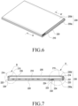
- FIG. 6 is an exploded perspective view illustrating the assembled state of an electronic device including an accessory according to various embodiments of the invention
- FIG. 7 is a cross-sectional view taken along line AA' in FIG. 6 , in which the inner structure of the electronic device including the accessory is illustrated
- FIG. 8A is an enlarged cross-sectional view of portion A in FIG. 7
- FIG. 8B is an enlarged cross-sectional view in portion B of FIG. 7 .
- the electronic device including an accessory includes first and second electronic devices 210 and 220 and an accessory structure 230.
- the accessory structure 230 may include a protective cover that protects the first electronic device (e.g., the first electronic device 210 in FIG. 6 ) and the second electronic device (e.g., the second electronic device 220 in FIG. 6 ).
- the accessory structure 230 will be described with reference to a protective cover by way of example but is not limited thereto. That is, the accessory structure 230 is variously applicable as long as the accessory structure 230 covers the first and second electronic devices 210 and 220.
- At least one side face of the first electronic device 210 includes a first curved face 214 formed to face third and fourth curved faces 231 and 232 of the accessory structure 230, which will be described later.
- the first curved face 214 includes at least one first magnet 215 to be attached to/detached from at least one third magnet 233 and at least one fourth magnet 234 included in the accessory structure 230, which will be described later.
- At least one side face of the first electronic device 220 includes a second curved face 223 formed to face third and fourth curved faces 231 and 232 of the accessory structure 230, which will be described later.
- the second curved face 223 includes at least one second magnet 224 to be attached to/detached from at least one third magnet 233 and at least one fourth magnet 234 included in the accessory structure 230, which will be described later.
- the accessory structure 230 includes third and fourth curved faces 231 and 232 to face the first and second curved faces 214 and 223 of the first and second electronic devices 210 and 220, and the third and fourth curved faces 231 and 232 includes at least one third magnet 233 and at least one fourth magnet 234 to be attached to/detached from the at least one first and second magnet 215 and at least one 224 of the first and second electronic devices 210 and 220 therein.
- the accessory structure 230 described above allows the first electronic device 210 to be mounted at various angles when the at least one first magnet 215 and the at least one second magnet 224 are attached to/detached from the at least one third magnet 233 and the at least one fourth magnet 234 of the first and second electronic devices 210 and 220 by magnetic force, and the first and second curved faces 214 and 223 of the first and second electronic devices 210 and 220 are rotated along the third and fourth curved faces 231 and 232 such that the accessory structure 230 is bent during the rotation. Therefore, it is possible to easily attach/detach the first and second electronic devices 210 and 220 to/from the accessory structure 230, thereby facilitating the use of the product.
- the separate mounting portion and hinge portion of a conventional electronic device are not required, and thus it is possible to reduce the thickness, volume, and weight of the product and to design a product to have a beautiful appearance.
- the accessory structure 230 includes first and second cover parts 230a and 230b.
- the first cover part 230a may be located on at least a portion of the front face of the first electronic device 210, and a third curved face 231 is formed at one side of the first cover part 230a to face the first curved face 214 of the first electronic device 210.
- the third curved face 231 includes therein at least one third magnet 233, which is attachable to/detachable from the at least one first magnet 215 of the first electronic device 210 by magnetic force so as to make the first curved face 214 of the first electronic device 210 rotatable along the third face 231 when rotated in the state in which the third magnet 233 is attached to the first magnet 215.
- a fourth curved face 232 formed to face the second face 223 of the second electronic device 220.
- the fourth curved face 232 includes therein at least one fourth magnet 234 to be attachable to/detachable from the at least one second magnet 224 of the second electronic device 220 by magnetic force and to make the second curved face 223 of the first electronic device 210 rotatable along the fourth curved face 232 when rotated in the state in which the fourth magnet 234 is attached to the second magnet 224.
- the second cover part 230b is rotatably connected to the first cover part 230a, and when rotated, the second cover part 230b is capable of being bent to face at least a portion of the rear face of the first electronic device 210 and to be located behind the first electronic device 210, so that the first electronic device 210 can be mounted at various angles.
- the second cover part 230b is used as a cradle, first, the second cover part 230b is rotatable from the first cover part 230a, and the first electronic device 210 is rotatable.
- the first curved face 214 of the first electronic device 210 is rotatable along the third curved face 231 of the first cover part 230a. That is, in the state in which the at least one first magnet 215 included in the first curved face 214 and the at least one third magnet 233 included in the third curved face 231 are attached to each other by magnetic force, the first curved face 214 of the first electronic device 210 is rotatable along the third curved face 231.
- the second cover part 230b since the second cover part 230b is provided with at least one bent portion 235 that allows the second cover part 230b to be bent, the second cover part 230b may be bent by the at least one bent portion 235 while being rotated, so that the second cover part 230b can be used as a cradle. At this time, the second cover part 230b may be attached to the at least one mounting magnet 216 included in the first electronic device 210 so that the use of the second cover part 220 as a cradle can be supported.
- the first cover part 230a may include at least one of a speaker, a microphone, a camera, a connector terminal, a key button, and a touch screen.
- the speaker may include a thin film speaker.
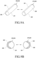
- FIG. 9A illustrate perspective views illustrating the operating state of first, second, third, and fourth magnets in an electronic device including an accessory according to various embodiments of the disclosure
- FIG. 9B illustrates cross-sectional views illustrating the operating state of the first, second, third, and fourth magnets of the configuration of the electronic device including an accessory according to various embodiments of the disclosure.
- the first, second, third, and fourth magnets 215, 224, 233, and 234 may have a cylindrical bar shape.
- the first, second, third, and fourth magnets 215, 224, 233, and 234 may have any of various bar shapes with a curved cross section other than a cylindrical bar shape.
- the first, second, third, and fourth magnets 215, 224, 233, and 234 may have a bar shape with an elliptical cross section.
- the first portion 241 of each of the first, second, third, and fourth magnets 215, 224, 233, and 234 may generate magnetic force and a second portion 242 of each of the first, second, third, and fourth magnets 215 opposite the first portion 241 of each of the first, second, third, and fourth magnets 215, 224, 233, and 234 may include a shield member 243 to block the magnetic force of each magnet.
- the shield member 243 may include a hemisphere shape.
- the shield member 243 may have a shape other than the hemisphere shape.
- a portion of the cylindrical bar may generate magnetic force, and the remaining portion of the cylindrical bar may include a shield member 243 that blocks the magnetic force.
- the shield member 243 may include a metal material.
- the shield member 243 will described with reference to a metal material by way of example but is not limited thereto. That is, various materials other than a metal material are applicable to the shield member 243 as long as the materials are capable of shielding the magnetic force of the magnet.
- the shield member may be made of a synthetic resin material.
- the first magnet 215 of the first electronic device 210 and the third magnet 233 of the first cover part 230a are attachable to/detachable from each other by magnetic force. That is, the first portions 241 of the first and third magnets 215 and 233, neither of which has a shield member 243, are attachable to/detachable from each other by magnetic force, and the shield members 243 included in the second portions 242 of the first and third magnets 215 and 233 opposite the first portions capable of shielding the magnetic force of the first and third magnets 215 and 233 and preventing the electronic components included in the first electronic device 210 from malfunctioning due to the magnetic force.
- the first curved face 214 of the first electronic device 210 is rotatable along the third curved face 231 of the first cover part 230a.
- the second magnet 224 of the second electronic device 220 and the fourth magnet 234 of the first cover part 230a are attachable to/detachable from each other by magnetic force. That is, the first portions 241 of the second and fourth magnets 224 and 234, neither of which has a shield member 243, are attachable to/detachable from each other by magnetic force, and the shield members 243 included in the second portions 242 of the second and fourth magnets 224 and 234 opposite the first portions are capable of shielding the magnetic force of the second and fourth magnets 224 and 234 and preventing the electronic components included in the second electronic device 220 from malfunctioning due to the magnetic force.
- the second curved face 223 of the second electronic device 220 is rotatable along the fourth curved face 232 of the first cover part 230a.
- FIG. 10 is an enlarged cross-sectional view illustrating an electronic device including an accessory according to various embodiments of the disclosure prior to operation
- FIG. 11 is an enlarged cross-sectional view illustrating the electronic device including the accessory according to various embodiments of the disclosure after operation
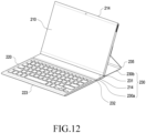
- FIG. 12 is a perspective view illustrating the operating state of the electronic device including the accessory according to various embodiments of the disclosure
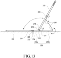
- FIG. 13 is a cross-sectional view illustrating the operating state of the electronic device including the accessory according to various embodiments of the disclosure.
- the electronic device including an accessory may include an accessory structure 230.
- the accessory structure 230 may include first and second cover parts 230a and 230b.
- first and second cover parts 230a and 230b For example, it is possible to make a first curved face 214 formed on one side surface of the first electronic device 210 face a third curved face 231 of the first cover part 230a, and it is possible to make a fourth curved face 232 of the first cover part 230a face a second curved face 223 formed on one side face of the second electronic device 220.
- a first magnet 215 included in the first curved face 214 is attachable to a third magnet 233 included in the third curved face 231 of the first cover part 230a by magnetic force
- the fourth magnet 234 included in the fourth curved face 232 of the first cover part 230a is attachable to the second magnet 224 included in the second curved face 223 by magnetic force.
- the second cover part 230b when the second cover part 230b is used as a cradle, since the second cover part 230b located behind the first electronic device 210 is rotatable from the first cover part 230a, and the first magnet 215 of the first electronic device 210 and the third magnet 233 of the first cover part 230a are attached to each other by a magnetic force, the first electronic device 210 is rotatable from the first cover part 230a. At this time, the first curved face 214 of the first electronic device 210 is rotatable along the third curved face 231 of the first cover part 230a. In this state, the second cover part 230b is capable of being bent by at least one bent portion 235 included therein.
- one end of the second cover part 230b is attachable to at least one mounting magnet 216 provided on the rear face of the first electronic device 210.
- the second cover part 230b is capable of facing the second curved face 223 of the second electronic device 220, and the fourth magnet 234 included in the fourth curved face 232 of the first cover part 230a is attachable to the second magnet 224 included in the second curved face 223 of the second electronic device 220 by magnetic force.
- the first electronic device 210 may be mounted to be inclined at a mounting angle ⁇ of, for example, 60 degrees from the floor.
- the second cover part 230b when the first and second cover parts 230a and 230b are used as a standing cradle or a typing cradle, the second cover part 230b is capable of being bent while being rotated, so that the second cover part 230b is capable of supporting the rear face of the first electronic device 210 so as to mount the first electronic device 210 in the standing state.
- the second electronic device 220 may be mounted such that typing can be performed thereon by attaching the fourth magnet 234 included in the fourth curved face 232 of the first cover portion 230a to the second magnet 224 included in the second curved face 223 of the second electronic device 220 by magnetic force and bringing the first cover part 230a into close contact with the floor.
- the first electronic device 210 may be a tablet PC including a display unit on which an image is capable of being viewed, and the second electronic device 220 may be a keyboard on which typing is capable of being performed.
- the first and second electronic devices 210 and 220 and the first cover part 230a may include a near-field communication module (e.g., the near-field communication module 192 in FIG. 1 ) such that the first and second electronic devices 210 and 220 and the first cover part 230a transmit and receive signals for near-field communication with each other.
- a near-field communication module e.g., the near-field communication module 192 in FIG. 1
- the near-field communication module 192 may include at least one of, for example, a cellular module, a Wi-Fi module, a Bluetooth module, a GNSS module, an NFC module, and an RF module.
- Various communication modules capable of near-field communication may be applicable as the near-field communication module (e.g., the near-field communication module 192 in FIG. 1 ) in addition to the disclosed module.
- a Bluetooth module may be applicable as the near-field communication module (e.g., the near-field communication module 192 in FIG. 1 ).
- the near-field communication module (e.g., the near-field communication module 192 in FIG. 1 ) may be provided, for example, as an independent module separately from a communication interface.
- the near-field communication module 192 (the near-field communication module 192 in FIG. 1 ) may change the operating mode under the control of a processor 120 (e.g., the processor 120 in FIG. 1 ).
- the processor 120 may control the near-field communication module (e.g., the near-field communication module 192 in FIG. 1 ) to transmit and receive data to and from the first and second electronic devices 210 and 220 and the first cover part 230a.
- the processor 120 may control the overall operation of the first and second electronic devices 210 and 220 and the first cover part 230a, and may perform control for the near-field communication function provided by the first and second electronic devices 210 and 220 and the first cover part 230a.
- the processor 120 is a device for driving an operating system (OS) and each component thereof.
- the processor 120 may be a central processing unit (CPU).
- the processor 120 may control activate or deactivate the near-field communication function of the near-field communication module (e.g., the near-field communication module 192 in FIG. 1 ) depending on whether the near-field communication modules (e.g., the near-field communication module 192 in FIG. 1 ) of the first and second electronic devices 210 and 220 and the near-field communication module (e.g., the near-field communication module 192 in FIG. 1 ) of the first cover part 230a are connected to each other.
- the near-field communication modules e.g., the near-field communication module 192 in FIG.
- the processor 120 activates the communication function of the near-field communication modules such that the near-field communication modules (e.g., the short-communication module 192 in FIG. 1 ) are in the communication state, and when the near-field communication modules (e.g., the short-range module 192 in FIG. 1 ) of the first and second electronic devices 210 and 220 and the near-field communication module (e.g., the near-field communication module 192 in FIG.
- the processor 120 deactivates the communication function of the near-field communication modules (e.g., the near-field communication modules (e.g., the near-field communication module 192 in FIG. 1 )). This may be performed as follows: the processor (e.g., the processor 120 in FIG. 1 ) transmits activation/deactivation setting information on the near-field communication function to the near-field communication modules (e.g., the near-field communication module 192 in FIG. 1 ), and the near-field communication modules receiving the same (e.g., the near-field communication module 192 in FIG. 1 ) store the activation/deactivation setting information and perform or block the communication function depending on the stored setting information.
- the processor e.g., the processor 120 in FIG. 1
- transmits activation/deactivation setting information on the near-field communication function to the near-field communication modules (e.g., the near-field communication module 192 in FIG. 1 )
- the near-field communication modules receiving the same e.g., the near-
- the processor 120 may activate/deactivate the near-field communication function of the near-field communication modules (e.g., the short-range-communication module 192 in FIG. 1 ) depending on on/off of the power supplies of the first and second electronic devices 210 and 220 and the first cover part 230a.
- the processor 120 transmits deactivation setting information to the near-field communication modules (e.g., the near-field communication module 192 in FIG. 1 ) such that the communication modules (e.g., the near-field communication module 192 in FIG. 1 ) are changed from "whether to activate/deactivate" to "deactivation.
- the near-field communication modules e.g., the near-field communication module 192 in FIG. 1
- the processor 120 transmits activation setting information to the near-field communication modules (e.g., the near-field communication module 192 in FIG. 1 ) such that the communication modules (e.g., the near-field communication module 192) are changed from "whether to activate/deactivate" to "activation". Subsequently, the near-field communication modules (e.g., the near-field communication module 192 in FIG. 1 ) are capable of performing the near-field communication function since the setting information is changed to the activation.
- the near-field communication modules e.g., the near-field communication module 192 in FIG. 1
- the near-field communication modules are capable of performing the near-field communication function since the setting information is changed to the activation.
- a communication interface provided in the processor 120 may perform data communication through a wireless communication network.
- the communication interface may perform data transmission/reception data using one or more communication methods, and for this purpose, the communication interface may include a plurality of communication interfaces, perform data transmission and reception based on different communication methods, respectively.
- the memory 130 stores information necessary for the operation of the first and second electronic devices 210 and 220 according to an embodiment of the disclosure, and may store various data for the near-field communication function.
- the first electronic device 210 when the at least one first magnet 215 of the first electronic device 210 and the at least one third magnet 233 of the accessory are attached to or detached from each other by magnetic force, the first electronic device 210 may perform an input mode or an operation mode, and when the at least one second magnet 224 of the second electronic device 220 and the at least one fourth magnet 234 of the accessory structure are attached to or detached from each other by magnetic force, the second electronic device 220 may perform an input mode or an operation mode.
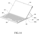
- FIG. 14 is a perspective view illustrating another mounting angle of the second cover part in the configuration of an electronic device including an accessory according to various embodiments of the disclosure
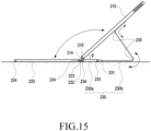
- FIG. 15 is a cross-sectional view illustrating another mounting angle of the second cover part in the configuration of an electronic device including an accessory according to various embodiments of the disclosure.
- an electronic device which includes an accessory, may include first and second electronic devices 210 and 220 and an accessory structure 230, and the accessory structure 230 may include first and second cover parts 230a and 230b.
- the second cover part 230b is used as a cradle, first, it is possible to rotate the second cover part 230b disposed on the rear face of the first electronic device 210 from the first cover part 230a.
- the first magnet 215 of the first electronic device 210 and the third magnet 233 of the first cover part 230a are attached to each other by magnetic force, it is possible to rotate the first electronic device 210 from the first cover part 230a.
- the first curved face 214 of the first electronic device 210 is rotatable along the third curved face 231 of the first cover part 230a. Then, it is possible to separate the first curved face 214 of the first electronic device 210 from the third curved face 231 of the first cover part 230a, and to make the first curved face 214 of the first electronic device 210 face the fourth curved face 232 of the first cover part 230a.
- the first magnet 215 of the first electronic device 210 is attachable to the fourth magnet 234 included in the fourth curved face 232 of the first cover part 230a by magnetic force.
- the second cover part 230b is capable of being bent by at least one bent portion 235 included therein.
- one end of the second cover part 230b is attachable to at least one mounting magnet 216 provided on the rear face of the first electronic device 210.
- the second cover part 230b is attachable to the second cover part 230b as a cradle.
- the fourth curved face 232 of the first cover part 230a faces the second curved face 223 of the second electronic device 220, and the fourth magnet 234 included in the fourth curved face 232 of the first cover part 230a is attachable to the second magnet 224 included in the second curved face 223 of the second electronic device 220 by magnetic force.
- the fourth magnet 234 included in the fourth curved face 232 of the first cover part 230a is attachable to the first and second magnets 215 and 224 included in the first and second curved faces 214 and 223 of the first and second electronic devices 210 and 220 by magnetic force.
- the first electronic device 210 may be mounted to be inclined at a mounting angle ⁇ of, for example, 40 degrees from the floor.
- the second cover part 230b when the first and second cover parts 230a and 230b are used as a standing cradle or a typing cradle, the second cover part 230b is capable of being bent while being rotated, so that the second cover part 230b is capable of supporting the rear face of the first electronic device 210 so as to mount the electronic device 10 in the standing state.
- the mounting angle ⁇ of the first electronic device 210 may become 40 degrees by being further laid down from 60 degrees from the floor.
- the second electronic device 220 may be mounted such that typing can be performed thereon by attaching the fourth magnet 234 included in the fourth curved face 232 of the first cover portion 230a to the second magnet 224 included in the second curved face 223 of the second electronic device 220 by magnetic force and bringing the first cover part 230a into close contact with the floor.
- the first electronic device 210 may be a tablet PC including a display unit on which an image is capable of being viewed, and the second electronic device 220 may be a keyboard on which typing is capable of being performed.
- the first and second electronic devices 210 and 220 and the first cover part 230a may include a near-field communication module (e.g., the near-field communication module 192 in FIG. 1 ) such that the first and second electronic devices 210 and 220 and the first cover part 230a transmit and receive signals for near-field communication with each other.
- a near-field communication module e.g., the near-field communication module 192 in FIG. 1
- the near-field communication modules 192 may change the input mode or the operating mode under the control of the processor.
- the processor may control the near-field communication modules (e.g., the near-field communication module 192 in FIG. 1 ) to transmit and receive data to and from the first and second electronic devices 210 and 220 and the first cover part 230a. Accordingly, the user may check data displayed on the display unit of the first electronic device 210 and may perform typing using the keyboard included in the second electronic device 220.
- the near-field communication modules e.g., the near-field communication module 192 in FIG. 1
- the processor may control the near-field communication modules (e.g., the near-field communication module 192 in FIG. 1 ) to transmit and receive data to and from the first and second electronic devices 210 and 220 and the first cover part 230a. Accordingly, the user may check data displayed on the display unit of the first electronic device 210 and may perform typing using the keyboard included in the second electronic device 220.
- the first electronic device 210 when the at least one first magnet 215 of the first electronic device 210 and the at least one third magnet 233 of the accessory are attached to or detached from each other by magnetic force, the first electronic device 210 may perform an input mode or an operation mode, and when the at least one second magnet 224 of the second electronic device 220 and the at least one fourth magnet 234 of the accessory are attached to or detached from each other by magnetic force, the second electronic device 200 may perform an input mode or an operation mode.
- FIG. 16 is a perspective view illustrating still another mounting angle of the second cover part in the configuration of an electronic device including an accessory according to various embodiments of the disclosure
- FIG. 17 is a cross-sectional view illustrating still another mounting angle of the second cover part in the configuration of an electronic device including an accessory according to various embodiments of the disclosure.
- the electronic device including an accessory may include first and second electronic devices 210 and 220 and an accessory structure 230.
- the accessory structure 230 may include first and second cover parts 230a and 230b.
- first when the second cover part 230b is used as a cradle, first, it is possible to rotate the second cover part 230b disposed on the rear face of the first electronic device 210 from the first cover part 230a. Then, it is possible to attach the first magnet 215 of the first electronic device 210 to the fourth magnet 234 of the first cover part 230a. It is possible to rotate the first electronic device 210 from the first cover part 230a.
- the first curved face 214 of the first electronic device 210 is rotatable along the fourth curved face 232 of the first cover part 230a.
- the first magnet 215 of the first electronic device 210 is rotatable in the state of being attached to the fourth magnet 234 included in the fourth curved face 232 of the first cover part 230a by magnetic force.
- the second cover part 230b is capable of being bent by at least one bent portion 235 included therein.
- the second cover part 230b is attachable to at least one mounting magnet 216 provided on the rear face of the first electronic device 210.
- the first electronic device 210 may be mounted to be inclined at a mounting angle ⁇ of 10 degrees from the floor. That is, the first electronic device 210 may be gently laid on the floor to form the above-mentioned mounting angle.
- the second electronic device 220 may be separated from the first electronic device 210 by a predetermined distance, and the second electronic device 220 may be in close contact with the floor.
- the first curved face 214 of the first electronic device 210 and the second curved face 223 of the second electronic device 220 may be separated from each other.
- the first electronic device 210 and the second electronic device 220 may be disposed in the state of being separated from each other by a predetermined distance.
- the second cover part 230b when the first and second cover parts 230a and 230b are used as a standing cradle or a typing cradle, the second cover part 230b is capable of being bent while being rotated, so that the second cover part 230b is capable of supporting the rear face of the first electronic device 210 so as to mount the electronic device 10 in the standing state.
- the first electronic device 210 may be mounted at a mounting angle ⁇ of 10 degrees from the floor.
- the second electronic device 220 may be separated from the first electronic device 210 and may be mounted such that typing can be performed thereon.
- the first electronic device 210 may be a tablet PC including a display unit on which an image is capable of being viewed, and the second electronic device 220 may be a keyboard on which typing is capable of being performed.
- the first and second electronic devices 210 and 220 and the first cover part 230a may include a near-field communication module (e.g., the near-field communication module 192 in FIG. 1 ) such that the first and second electronic devices 210 and 220 and the first cover part 230a transmit and receive signals for near-field communication with each other.
- a near-field communication module e.g., the near-field communication module 192 in FIG. 1
- the near-field communication modules 192 may change the input mode or the operating mode under the control of the processor (e.g., the processor 120 in FIG. 1 ).
- the processor may control the near-field communication module (e.g., the near-field communication module 192 in FIG. 1 ) to transmit/receive data to/from the first and second electronic devices 210 and 220 and the first cover part 230a. Accordingly, the user may check data displayed on the display unit of the first electronic device 210 and may perform typing using the keyboard included in the second electronic device 220.
- the near-field communication module e.g., the near-field communication module 192 in FIG. 1
- the first electronic device 210 when the at least one first magnet 215 of the first electronic device 210 and the at least one third magnet 233 of the accessory structure are attached to or detached from each other by magnetic force, the first electronic device 210 may perform an input mode or an operation mode, and when the at least one second magnet 224 of the second electronic device 220 and the at least one fourth magnet 234 of the accessory are attached to or detached from each other by magnetic force, the second electronic device 220 may perform an input mode or an operation mode.
- FIG. 18 is a perspective view illustrating still another mounting angle of the second cover part in the configuration of an electronic device including an accessory according to various embodiments of the disclosure
- FIG. 19 is a cross-sectional view illustrating another mounting angle of the second cover part in the configuration of an electronic device including an accessory according to various embodiments of the disclosure.
- an electronic device including an accessory may include first and second electronic devices 210 and 220 and an accessory structure 230, and the accessory structure 230 may include first and second cover parts 230a and 230b.
- the second cover part 230b is used as a cradle, first, it is possible to rotate the second cover part 230b disposed on the rear face of the first electronic device 210 from the first cover part 230a. Then, it is possible to attach the first magnet 215 of the first electronic device 210 to the fourth magnet 234 of the first cover part 230a. In this state, it is possible to rotate the first electronic device 210 from the first cover part 230a.
- the first curved face 214 of the first electronic device 210 is rotatable along the fourth curved face 232 of the first cover part 230a.
- the first magnet 215 of the first electronic device 210 is rotatable in the state of being attached to the fourth magnet 234 included in the fourth curved face 232 of the first cover part 230a by magnetic force.
- the second cover part 230b is capable of being bent by at least one bent portion 235 included therein.
- the second cover part 230b is attachable to at least one mounting magnet 216 provided on the rear face of the first electronic device 210.
- the first electronic device 210 may be mounted to be inclined at a mounting angle ⁇ of 65 degrees from the floor. That is, the first electronic device 210 may form a steep inclination angle from the floor.
- the second electronic device 220 may be separated from the first electronic device 210 by a predetermined distance, and the second electronic device 220 may be in close contact with the floor. That is, the first curved face 214 of the first electronic device 210 and the second curved face 223 of the second electronic device 220 may be separated from each other. The first electronic device 210 and the second electronic device 220 may be disposed in the state of being separated from each other by a predetermined distance.
- the second cover part 230b when the first and second cover parts 230a and 230b are used as a standing cradle or a typing cradle, the second cover part 230b is capable of being bent while being rotated, so that the second cover part 230b is capable of supporting the rear face of the first electronic device 210 so as to mount the first electronic device 210 in the standing state.
- the first electronic device 210 may be mounted at a mounting angle ⁇ of 65 degrees from the floor.
- the second electronic device 220 may be separated from the first electronic device 210 and may be mounted such that typing can be performed thereon.
- the first electronic device 210 may be a tablet PC including a display unit on which an image is capable of being viewed, and the second electronic device 220 may be a keyboard on which typing is capable of being performed.
- the first and second electronic devices 210 and 220 and the first cover part 230a may include a near-field communication module (e.g., the near-field communication module 192 in FIG. 1 ) such that the first and second electronic devices 210 and 220 and the first cover part 230a transmit and receive signals for near-field communication with each other.
- a near-field communication module e.g., the near-field communication module 192 in FIG. 1
- the near-field communication modules 192 e.g., the near-field communication module 192 in FIG.
- the processor may change the input mode or the operating mode under the control of the processor (e.g., the processor 120 in FIG. 1 ).
- the processor e.g., the processor 120 in FIG. 1
- the processor may control the near-field communication module (e.g., the near-field communication module 192 in FIG. 1 ) to transmit and receive data to and from the first and second electronic devices 210 and 220 and the first cover part 230a. Accordingly, the user may check data displayed on the display unit of the first electronic device 210, and may perform typing using the keyboard included in the second electronic device 220.
- the first electronic device 210 when the at least one first magnet 215 of the first electronic device 210 and the at least one third magnet 233 of the accessory structure are attached to or detached from each other by magnetic force, the first electronic device 210 may perform an input mode or an operation mode, and when the at least one second magnet 224 of the second electronic device 220 and the at least one fourth magnet 234 of the accessory structure are attached to or detached from each other by magnetic force, the second electronic device 220 may perform an input mode or an operation mode.
- FIG. 20 is a perspective view illustrating the assembled state of an electronic device including an accessory according to various other embodiments of the disclosure that are not claimed.
- FIG. 21 is a cross-sectional view taken along line B-B' in FIG. 20 .
- the electronic device including an accessory includes an electronic device 310 and an accessory structure 320.
- first curved faces 311 may be formed on the opposite side faces of the electronic device 310 to face a second curved face 321 of the accessory structure 320, which will be described later.
- Each of the first curved faces 311 includes therein at least one first magnet 312 to be attached to/detached from at least one second magnet 322 included in the accessory structure 320.
- the accessory structure 320 may be located on the front face of the electronic device 310, and includes the second curved face 321 to face the first curved faces 311 of the electronic device 310, and includes at least one second magnet 322 in the second curved face 321 to be attached to/detached from the at least one first magnet 312 of the electronic device 310.
- the at least one second magnet 322 is attachable to/detachable from the at least one first magnet 312 of the electronic device 310 by magnetic force, and the second curved face 321 of the cover part 320 is rotatable along the first curved face 311 of the electronic device 310.
- the accessory structure 320 is capable of being bent so as to allow the electronic device 310 to be mounted at various angles. Therefore, it is possible to easily attach/detach the electronic device 310 to/from the accessory structure 320, thereby facilitating the use of the product. Further, it is possible to freely adjust the mounting angle of the electronic device 310, thereby facilitating the use of the accessory as well as improving the convenience of the user.
- the separate mounting portion and hinge portion of the conventional electronic device are not required, and thus it is possible to reduce the thickness, volume, and weight of the product and to design a product to have a beautiful appearance.
- the accessory structure 320 includes a cover part 320.
- the cover part 320 may be located on the front face of the first electronic device 310, and the second curved face 321 is formed at one side of the cover part 320 to face the first curved face 311 of the electronic device 310.
- the second curved face 321 includes therein at least one second magnet 322, which is attachable to/detachable from the at least one first magnet 312 of the electronic device 310 by magnetic force so as to make the second curved face 321 rotatable along the first face 311 of the first electronic device 310 when rotated in the state in which the second magnet 322 is attached to the first magnet 312.
- the cover part 320 is capable of being bent to face at least a portion of the rear face of the electronic device 310 and to be located behind the electronic device 310, so that the electronic device 310 can be mounted at various angles.
- the cover part 320 when the cover part 320 is used as a cradle, the cover part 320 may be rotated away from the front face of the electronic device 310. At this time, the second curved face 321 of the cover part 320 is rotatable along the first curved face 311 of the electronic device 310. In the state in which the at least one first magnet 312 included in the first curved face 311 and the at least one second magnet 322 included in the second curved face 321 are attached to each other by magnetic force, the second curved face 321 of the cover part 320 is rotatable along the first curved face 311 of the electronic device 310. In this state, since the cover part 320 is provided with at least one bent portion (e.g., the bent portion 323 in FIG.
- the cover part 320 may be bent by the at least one bent portion (e.g., the bent portion 323 in FIG. 22C ) while being rotated, so that the cover part 320 can be used as a cradle.
- the cover part 320 may be attached to the at least one mounting magnet (e.g., the mounting magnet 313 in FIG. 21 ) included in the electronic device 310, so that the use of the cover part 320 as a cradle can be supported.
- first and second magnets 312 and 322 are the same as those of the first, second, third, and fourth magnets 215, 224, 233 and 234 shown in FIGS. 9A and 9B , descriptions thereof will be omitted.
- FIG. 22A is a perspective view illustrating the operating state of the electronic device including the accessory according to various other embodiments of the disclosure that are not claimed
- FIG. 22B is a perspective view illustrating the operating state of the electronic device including the accessory according to various other embodiments of the disclosure that are not claimed
- FIG. 22C is a perspective view illustrating the operating state of the electronic device including the accessory according to various embodiments that are not claimed
- FIG. 23A is a cross-sectional view illustrating the operating state of the electronic device including the accessory according to various other embodiments of the disclosure that are not claimed
- FIG. 23B is a cross-sectional view illustrating the operating state of the electronic device including the accessory according to various other embodiments of the disclosure that are not claimed
- FIG. 23C is a cross-sectional view illustrating the operating state of the electronic device including the accessory according to various other embodiments of the disclosure that are not claimed.
- an electronic device including an accessory may include an electronic device 310 and an accessory structure 320, and the accessory structure 320 may include a cover part 320.
- the first curved faces 311 formed on the opposite sides of the electronic device 310 are capable of facing the second curved face 321 of the cover part 320.
- the first magnet 312 included in each of the first curved faces 311 is attachable to the second magnet 322 included in the second curved face 321 of the cover part 320 by magnetic force.
- the cover part 320 disposed on the front face of the electronic device 310 may be rotated. Then, since the first magnet 312 of the electronic device 310 and the second magnet 322 of the cover part 320 are attached to each other by magnetic force, it is possible to rotate the cover part 320 from the first electronic device 310. As illustrated in FIGS. 22B and FIG. 23B , the second curved face 321 of the cover part 320 is rotatable along the first curved face 311 of the first electronic device 310. In this state, as illustrated in FIGS.
- the cover part 320 may be bent due to the at least one bent portion 323 included in the cover part 320.
- one end of the cover part 320 is attachable to at least one mounting magnet (e.g., the mounting magnet 313 in FIG. 21 ) provided on the rear face of the electronic device 310.
- FIG. 24A is a cross-sectional view illustrating the operating state of the first and second magnets 312 and 322 in the configuration of the electronic device 310 including an accessory according to various other embodiments of the disclosure that are not claimed
- FIG. 24B is a cross-sectional view illustrating the operating state of the first and second magnets 312 and 322 in the configuration of the electronic device 310 including an accessory according to various other embodiments of the disclosure that are not claimed
- FIG. 24C is a cross-sectional view illustrating the operating state of the first and second magnets 312 and 322 in the configuration of the electronic device 310 including an accessory according to various other embodiments of the disclosure that are not claimed
- FIG. 24D is a cross-sectional view illustrating the operating state of the first and second magnets 312 and 322 in the configuration of the electronic device 310 including an accessory according to various other embodiments of the disclosure that are not claimed.
- the cover part 320 may be positioned on the front face of the electronic device 310, and the second magnet 322 of the cover part 320 may be attached to the first magnet 312 of the electronic device 310 by magnetic force.
- the second curved face 321 of the cover part 320 is rotatable along the first curved face 311 of the electronic device 310 in the state in which the second magnet 322 of the cover part 320 and the first magnet 312 of the electronic device 310 are attached to each other by the magnetic force. That is, the second curved face 321 of the cover part 320 is capable of being moved from the front face to the rear face of the electronic device 310 while rotating along the first curved face 311 of the electronic device 310.
- the cover part 320 may rotate away from the electronic device 310, that is, the second curved face 321 of the cover part 320 may rotate from the start position to the end position of the first curved face 311 of the electronic device 310 while rotating along the first face 311 of the electronic device 310. At this time, the cover part 320 may rotate the rear face of the electronic device 310, which is the end position.
- the cover part 320 may be located on the rear face of the electronic device 310 simultaneously when the second curved face 321 of the cover part 320 rotates from the end position of the first curved face 311 of the electronic device 310.
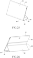
- FIG. 25 is a perspective view illustrating the operating state of a cover part 320 in the configuration of an electronic device 310 according to various other embodiments of the disclosure that are not claimed
- FIG. 26 is a perspective view illustrating the operating state of a cover part 320 in the configuration of the electronic device 310 according to various other embodiments of the disclosure that are not claimed.
- the cover part 320 when the cover part 320 is used as a cradle, first, the second curved face 321 of the cover part 320 rotates along the first curved face 311 of the electronic device 310. In this state, the cover part 320 may be bent so as to be disposed on the rear face of the electronic device 310 and to support the electronic device 310, so that the cover part 320 can be used as a cradle.
- the second curved face 321 of the cover part 320 faces the first curved face 311 of the electronic device 310, and the second magnet 322 included in the second curved face 321 of the cover part 320 is attachable to the first magnet 312 included in the first curved face 311 of the electronic device 310 by magnetic force.
- the electronic device 310 may be mounted to be inclined at a mounting angle of a predetermined angle from the floor.
- the cover part 320 when the cover part 320 is used as a standing cradle or a typing cradle, the cover part 320 is capable of being bent while being rotated, so that the cover part 320 is capable of supporting the rear face of the electronic device 310 so as to mount the electronic device 310 in the standing state.
- the electronic device 310 and the cover part 320 are laid on the floor in the state of being coupled as described above, the electronic device 310 may be mounted such that typing can be performed thereon.
- the electronic device 310 may be a tablet PC including a display unit on which an image is capable of being viewed.
- the cover part 320 may include at least one of a speaker, a microphone, a camera, a connector terminal, a key button, and a touch screen.
- each of the electronic device 310 and the cover part 320 may include a near-field communication module (e.g., the near-field communication module 192 in FIG. 1 ) such that the electronic device 310 and the cover part 320 transmit and receive signals for near-field communication with each other.
- a near-field communication module e.g., the near-field communication module 192 in FIG. 1
- the near-field communication module 192 may include at least one of, for example, a cellular module, a Wi-Fi module, a Bluetooth module, a GNSS module, an NFC module, and an RF module.
- Various communication modules capable of near-field communication may be applicable as the near-field communication module (e.g., the near-field communication module 192 in FIG. 1 ) in addition to the disclosed module.
- a Bluetooth module may be applicable as the near-field communication module (e.g., the near-field communication module 192 in FIG. 1 ).
- the near-field communication module (e.g., the near-field communication module 192 in FIG. 1 ) may be provided, for example, as an independent module separately from a communication interface.
- the near-field communication module 192 (e.g., the near-field communication module 192 in FIG. 1 ) may change the input mode and operating mode under the control of a processor 120 (e.g., the processor 120 in FIG. 1 ).
- the processor (e.g., the processor 120 in FIG. 1 ) may control the near-field communication module (e.g., the near-field communication module 192 in FIG. 1 ) to transmit/receive data to/from the electronic device 310 and the cover part 320.
- the processor 120 may control the overall operation of the electronic device 310 and the cover part 320, and may perform control for the near-field communication function provided by the electronic device 310 and the cover part 320.
- the processor 120 is a device for driving an operating system (OS) and each component thereof.
- the processor 120 may be a central processing unit (CPU). Since the specific operation of the near-field communication modules (e.g., the short-range module 192 in FIG. 1 ) have been described in connection with the embodiments related to FIGS. 10 to 14 , a description thereof will be omitted.
- the electronic device when the magnet 312 of the electronic device 310 is attached to/detached from the magnet 322 of the accessory structure by magnetic force, the electronic device may perform an input mode or an operation mode.
Landscapes
- Engineering & Computer Science (AREA)
- Theoretical Computer Science (AREA)
- Computer Hardware Design (AREA)
- General Engineering & Computer Science (AREA)
- Human Computer Interaction (AREA)
- Physics & Mathematics (AREA)
- General Physics & Mathematics (AREA)
- Microelectronics & Electronic Packaging (AREA)
- Computer Networks & Wireless Communication (AREA)
- Signal Processing (AREA)
- Casings For Electric Apparatus (AREA)
- Telephone Set Structure (AREA)
Claims (12)
- Appareil électronique comportant un accessoire, l'appareil électronique comprenant :un premier appareil électronique (210) ayant une première face incurvée (214) sur au moins une face latérale et comportant au moins un premier aimant (215) dans la première face incurvée (214), un deuxième appareil électronique (220) ayant une deuxième face incurvée (223) sur au moins une face latérale et comportant au moins un deuxième aimant (224) dans la deuxième face incurvée (223),une structure d'accessoire (230) comportant des troisième et quatrième faces incurvées (231, 232) faisant face aux première et deuxième faces incurvées (214, 223), et comportant respectivement au moins un troisième aimant (233) et au moins un quatrième aimant (234) dans la troisième face incurvée (231) et la quatrième face incurvée (232) ;caractérisé en ce quela structure d'accessoire (230) comprend une première partie de rabat (230a) susceptible d'être placée sur une portion d'une face avant du premier appareil électronique (210) et comportant la troisième face incurvée (231) formée sur un côté de celle-ci pour faire face à la première face incurvée (214) du premier appareil électronique (210) et la quatrième face incurvée (232) formée sur un autre côté de celle-ci pour faire face à la deuxième face incurvée (223) du deuxième appareil électronique (220), et comprend une deuxième partie de rabat (230b) qui est susceptible d'être placée sur une face arrière du premier appareil électronique (210), reliée pivotante à la première partie de rabat (230a) et capable d'être courbée pendant qu'elle pivote afin de faire face à au moins une portion de la face arrière du premier appareil électronique (210) et qui est conçue pour permettre au premier appareil électronique (210) d'être monté selon divers angles de montage distincts lorsque l'au moins un premier aimant (215) du premier appareil électronique (210) et l'au moins un deuxième aimant (224) du deuxième appareil électronique (220) sont fixés ou détachés vis-à-vis dudit au moins un troisième aimant (233) et dudit au moins un quatrième aimant (234) de la structure d'accessoire (230) par force magnétique et que les première et deuxième faces incurvées (214, 223) des premier et deuxième appareils électroniques (210, 220) pivotent le long des troisième et quatrième faces incurvées (231, 232) de la structure d'accessoire de telle façon que la structure d'accessoire (230) est courbée sous l'effet du pivotement des premier et deuxième appareils électroniques (210, 220), etles première, deuxième, troisième et quatrième faces incurvées (214, 223, 231, 232) sont convexes.
- Appareil électronique selon la revendication 1, dans lequel le premier appareil électronique (210) comprend un ordinateur portable, un mini-PC portatif, un smartphone et/ou une tablette, et le deuxième appareil électronique (220) comprend un clavier.
- Appareil électronique selon la revendication 1, dans lequel chacun des premier, deuxième, troisième et quatrième aimants (215, 224, 233, 234) a une forme de barre cylindrique.
- Appareil électronique selon la revendication 3, dans lequel une première portion (241) de chacun des premier, deuxième, troisième et quatrième aimants (215, 224, 233, 234) génère une force magnétique, et dans lequel une deuxième portion (242) de chacun des premier, deuxième, troisième et quatrième aimants (215, 224, 233, 234) comporte un élément de blindage (243) conçu pour bloquer la force magnétique de chacun des aimants (215, 224, 233, 234), et
dans lequel l'élément de blindage (243) comprend un matériau métallique ou un matériau à base de résine synthétique qui bloque la force magnétique de chacun des aimants (215, 224, 233, 234). - Appareil électronique selon la revendication 3, dans lequel chacune des première, deuxième, troisième et quatrième faces incurvées (214, 223, 231, 232) est de forme circulaire, hémisphérique et/ou elliptique en section transversale.
- Appareil électronique selon la revendication 1, dans lequel la première partie de rabat (230a) comporte un haut-parleur, un microphone, une caméra, une borne de connecteur, un bouton et/ou un écran tactile.
- Appareil électronique selon la revendication 1, dans lequel la deuxième partie de rabat (230b) comporte au moins une portion courbée (235) qui permet à la deuxième partie de rabat (230b) d'être courbée.
- Appareil électronique selon la revendication 7, dans lequel, lorsque la deuxième partie de rabat (230b) est utilisée ou n'est pas utilisée comme support, la deuxième partie de rabat (230b) est fixée ou détachée vis-à-vis d'au moins un aimant de montage (216) présent dans le premier appareil électronique (210).
- Appareil électronique selon la revendication 8, dans lequel le premier appareil électronique (210), le deuxième appareil électronique (220) et la première partie de rabat (230a) comportent chacun un module de communication en champ proche tel que les premier et deuxième appareils électroniques (210, 220) et la première partie de rabat (230a) transmettent et reçoivent un signal de communication en champ proche entre eux.
- Appareil électronique selon la revendication 8 ou 9, dans lequel, lorsque la deuxième partie de rabat (230b) est utilisée comme support, le premier aimant (215) du premier appareil électronique (210) est fixé au troisième aimant (233) de la première partie de rabat (230a), la première face incurvée (214) du premier appareil électronique (210) est pivotée le long de la troisième face incurvée (231) de la première partie de rabat (230a),la deuxième partie de rabat (230b) est pivotée et courbée pour être fixée à l'au moins un aimant de montage (216) prévu sur la face arrière du premier appareil électronique (210), permettant d'utiliser la deuxième partie de rabat (230b) comme un support, etle deuxième aimant (224) du deuxième appareil électronique (220) est fixé ou détaché vis-à-vis du quatrième aimant (234) de la première partie de rabat (230a).
- Appareil électronique selon la revendication 9, dans lequel, lorsque le premier appareil électronique (210) est monté sous différents angles, le premier aimant (215) du premier appareil électronique (210) est séparé du troisième aimant (233) de la première partie de rabat (230a) et est fixé au quatrième aimant (234), la première face incurvée (214) du premier appareil électronique (210) est pivotée le long de la quatrième face incurvée (232) de la première partie de rabat (230a),la deuxième partie de rabat (230b) est pivotée et courbée pour être fixée à l'au moins un aimant de montage (216) prévu sur la face arrière du premier appareil électronique (210), et la deuxième partie de rabat (230b) est placée de manière à faire face à au moins une portion de la face arrière du premier appareil électronique (210), permettant d'utiliser la deuxième partie de rabat (230b) comme un berceau, etle deuxième aimant (224) du deuxième appareil électronique (230) est fixé ou détaché vis-à-vis du quatrième aimant (234) de la première partie de rabat (230a).
- Appareil électronique selon la revendication 1, dans lequel le premier appareil électronique (210) est conçu pour réaliser un mode d'entrée ou un mode de fonctionnement sous l'effet de la fixation ou du détachement de l'au moins un premier aimant (215) du premier appareil électronique (210) vis-à-vis de l'au moins un troisième aimant (233) de la structure d'accessoire (230) par force magnétique, et
le deuxième appareil électronique (220) est conçu pour réaliser un mode d'entrée ou un mode de fonctionnement sous l'effet de la fixation ou du détachement de l'au moins un deuxième aimant (224) du deuxième appareil électronique (220) vis-à-vis de l'au moins un quatrième aimant (234) de la structure d'accessoire (230) par force magnétique.
Applications Claiming Priority (2)
| Application Number | Priority Date | Filing Date | Title |
|---|---|---|---|
| KR1020170063153A KR102435011B1 (ko) | 2017-05-22 | 2017-05-22 | 액세사리를 포함하는 전자 장치 |
| PCT/KR2018/005776 WO2018216981A1 (fr) | 2017-05-22 | 2018-05-21 | Dispositif électronique comprenant un accessoire |
Publications (3)
| Publication Number | Publication Date |
|---|---|
| EP3633488A1 EP3633488A1 (fr) | 2020-04-08 |
| EP3633488A4 EP3633488A4 (fr) | 2020-06-10 |
| EP3633488B1 true EP3633488B1 (fr) | 2024-05-22 |
Family
ID=64396806
Family Applications (1)
| Application Number | Title | Priority Date | Filing Date |
|---|---|---|---|
| EP18805704.6A Active EP3633488B1 (fr) | 2017-05-22 | 2018-05-21 | Dispositif électronique comprenant un accessoire |
Country Status (4)
| Country | Link |
|---|---|
| US (1) | US11048304B2 (fr) |
| EP (1) | EP3633488B1 (fr) |
| KR (1) | KR102435011B1 (fr) |
| WO (1) | WO2018216981A1 (fr) |
Families Citing this family (22)
| Publication number | Priority date | Publication date | Assignee | Title |
|---|---|---|---|---|
| US10912213B2 (en) * | 2017-12-27 | 2021-02-02 | Lg Display Co., Ltd. | Foldable display device maintaining a folding angle by magnetic force |
| KR102544477B1 (ko) | 2019-01-07 | 2023-06-19 | 삼성전자주식회사 | 전자 장치, 전자 장치 보호 케이스 및 그 전자 장치의 디스플레이 방법 |
| KR102757429B1 (ko) * | 2019-03-20 | 2025-01-20 | 삼성전자주식회사 | 듀얼 디스플레이 및 키보드를 포함하는 전자 장치 |
| US10996718B2 (en) | 2019-04-03 | 2021-05-04 | Dell Products, L.P. | Foldable case for a multi-form factor information handling system (IHS) with a detachable keyboard |
| KR102763743B1 (ko) | 2019-07-29 | 2025-02-10 | 삼성전자주식회사 | 펜 수납부를 포함하는 커버 및 이를 포함하는 전자 장치 |
| DE102021201105A1 (de) * | 2020-03-09 | 2021-09-09 | Apple Inc. | Zubehörvorrichtungen für elektronische vorrichtungen |
| KR102895694B1 (ko) * | 2020-03-31 | 2025-12-05 | 삼성전자 주식회사 | 액세서리를 장착할 수 있는 전자 장치 |
| CN111557656B (zh) * | 2020-05-26 | 2020-11-24 | 魏月玲 | 一种紧急状况供药急救装置 |
| US12066869B2 (en) * | 2020-09-18 | 2024-08-20 | Apple Inc. | Accessory device with dual angle setting using a single fulcrum point |
| JP2022170037A (ja) * | 2021-04-28 | 2022-11-10 | キヤノン株式会社 | 電子機器 |
| WO2023084310A2 (fr) | 2021-11-12 | 2023-05-19 | Remarkable As | Support de dispositif pour supporter un dispositif informatique |
| US12299218B2 (en) | 2023-06-11 | 2025-05-13 | Remarkable As | Active pen-stylus precise eraser |
| WO2024058545A1 (fr) * | 2022-09-13 | 2024-03-21 | 삼성전자 주식회사 | Dispositif électronique comprenant un clavier |
| WO2024204963A1 (fr) * | 2023-03-31 | 2024-10-03 | 삼성전자주식회사 | Dispositif accessoire comprenant une pluralité d'aimants |
| USD1092467S1 (en) | 2023-11-13 | 2025-09-09 | Remarkable As | Tablet computer |
| USD1123935S1 (en) | 2024-02-08 | 2026-04-28 | Remarkable As | Marker |
| USD1106208S1 (en) | 2024-02-08 | 2025-12-16 | Remarkable As | Marker |
| USD1107023S1 (en) | 2024-02-08 | 2025-12-23 | Remarkable As | Marker |
| USD1115781S1 (en) | 2024-05-03 | 2026-03-03 | Remarkable As | Folio |
| CN121300641A (zh) | 2024-07-08 | 2026-01-09 | 瑞马科宝股份有限公司 | 标记笔保护系统 |
| CN121300642A (zh) | 2024-07-08 | 2026-01-09 | 瑞马科宝股份有限公司 | 标记笔书写系统 |
| CN121300639A (zh) | 2024-07-08 | 2026-01-09 | 瑞马科宝股份有限公司 | 可更换导电标记笔尖端 |
Citations (2)
| Publication number | Priority date | Publication date | Assignee | Title |
|---|---|---|---|---|
| US20120066865A1 (en) * | 2010-09-17 | 2012-03-22 | Apple Inc. | Foldable accessory device |
| US20140043121A1 (en) * | 2012-08-08 | 2014-02-13 | Apple Inc. | Accessory device |
Family Cites Families (32)
| Publication number | Priority date | Publication date | Assignee | Title |
|---|---|---|---|---|
| US8344836B2 (en) * | 2010-09-17 | 2013-01-01 | Apple Inc. | Protective cover for a tablet computer |
| US9335793B2 (en) * | 2011-01-31 | 2016-05-10 | Apple Inc. | Cover attachment with flexible display |
| US8907752B2 (en) * | 2011-09-12 | 2014-12-09 | Justin Richard Wodrich | Integrated inductive charging in protective cover |
| US9134807B2 (en) * | 2012-03-02 | 2015-09-15 | Microsoft Technology Licensing, Llc | Pressure sensitive key normalization |
| US9426905B2 (en) * | 2012-03-02 | 2016-08-23 | Microsoft Technology Licensing, Llc | Connection device for computing devices |
| US9007157B2 (en) * | 2012-08-28 | 2015-04-14 | Apple Inc. | Magnetic assembly |
| KR102060153B1 (ko) * | 2013-01-24 | 2020-01-09 | 삼성전자주식회사 | 커버, 이를 이용하는 전자 장치 및 그 동작 방법 |
| US20140211393A1 (en) * | 2013-01-30 | 2014-07-31 | Bing-Zhang LEE | Detachable rotary extended keyboard plate |
| TWM475620U (en) * | 2013-05-30 | 2014-04-01 | Compal Electronics Inc | Electronic device |
| US9485338B2 (en) | 2013-09-04 | 2016-11-01 | Apple Inc. | Features and manufacturing methods for a case for a portable electronic device |
| WO2015070321A1 (fr) * | 2013-11-13 | 2015-05-21 | Szeto Timothy Jing Yin | Connecteurs magnétiques |
| US20150263776A1 (en) * | 2014-03-11 | 2015-09-17 | Hewlett-Packard Development Company, L.P. | Protective cover for a device |
| KR20150110244A (ko) * | 2014-03-21 | 2015-10-02 | (주)엠플러스 | 다극자화를 통한 패턴화된 극성을 갖는 자석부착모듈 및 이를 이용한 전자기기 케이스 |
| CN114637375B (zh) | 2014-03-28 | 2025-01-28 | 英特尔公司 | 计算设备中磁力的调节 |
| US20150280768A1 (en) * | 2014-03-31 | 2015-10-01 | Dean Shoes Company Ltd. | Protective cover for a tablet |
| KR102207039B1 (ko) * | 2014-06-11 | 2021-01-25 | 삼성전자주식회사 | 액세서리 장치 |
| TWI612871B (zh) * | 2014-09-26 | 2018-01-21 | 仁寶電腦工業股份有限公司 | 電子裝置 |
| KR102239820B1 (ko) * | 2014-10-08 | 2021-04-13 | 삼성전자주식회사 | 보호 커버 |
| DE102015116490A1 (de) * | 2014-11-19 | 2016-05-19 | Rosenberger Hochfrequenztechnik Gmbh & Co. Kg | Magnetische Verbindungsvorrichtung |
| KR20160101477A (ko) * | 2015-02-17 | 2016-08-25 | 삼성전자주식회사 | 키보드 일체형 태블릿 커버를 가지는 전자 장치 |
| KR102304063B1 (ko) * | 2015-03-23 | 2021-09-24 | 삼성전자주식회사 | 보호 커버 |
| JP6539409B2 (ja) * | 2015-09-04 | 2019-07-03 | アップル インコーポレイテッドApple Inc. | ポータブル電子デバイスのためのフレキシブルなキーボードアクセサリ |
| US10579097B2 (en) * | 2015-09-04 | 2020-03-03 | Apple Inc. | Electronic device with contacts flush with housing |
| US9778705B2 (en) * | 2015-09-04 | 2017-10-03 | Apple Inc. | Electronic device with moveable contacts at an exterior surface |
| US9774136B2 (en) * | 2015-12-02 | 2017-09-26 | Nanoport Technology Inc. | Self-aligning connector |
| KR102439789B1 (ko) * | 2016-01-04 | 2022-09-02 | 삼성전자주식회사 | 거치 기능을 가지는 전자 장치 |
| US20190025889A1 (en) * | 2016-01-14 | 2019-01-24 | Nanoport Technology Inc. | Pivotally engageable modular electronic devices and methods of operation |
| US20170257146A1 (en) * | 2016-03-01 | 2017-09-07 | Nanoport Technology Inc. | Facilitating alignment of wireless elements for ultra short range wireless interaction |
| CN210167862U (zh) * | 2016-11-21 | 2020-03-20 | 株式会社村田制作所 | 电子设备 |
| JP2018200522A (ja) * | 2017-05-26 | 2018-12-20 | レノボ・シンガポール・プライベート・リミテッド | 電子機器 |
| KR102423134B1 (ko) * | 2017-06-12 | 2022-07-21 | 삼성전자주식회사 | 복수의 하우징들을 포함하는 전자 장치 |
| KR102417002B1 (ko) * | 2017-06-28 | 2022-07-05 | 삼성전자 주식회사 | 두 개의 디스플레이를 구비하는 전자 장치 및 이의 화면 운용 방법 |
-
2017
- 2017-05-22 KR KR1020170063153A patent/KR102435011B1/ko active Active
-
2018
- 2018-05-21 EP EP18805704.6A patent/EP3633488B1/fr active Active
- 2018-05-21 WO PCT/KR2018/005776 patent/WO2018216981A1/fr not_active Ceased
- 2018-05-21 US US16/612,892 patent/US11048304B2/en active Active
Patent Citations (2)
| Publication number | Priority date | Publication date | Assignee | Title |
|---|---|---|---|---|
| US20120066865A1 (en) * | 2010-09-17 | 2012-03-22 | Apple Inc. | Foldable accessory device |
| US20140043121A1 (en) * | 2012-08-08 | 2014-02-13 | Apple Inc. | Accessory device |
Also Published As
| Publication number | Publication date |
|---|---|
| US20200166973A1 (en) | 2020-05-28 |
| WO2018216981A1 (fr) | 2018-11-29 |
| EP3633488A1 (fr) | 2020-04-08 |
| KR102435011B1 (ko) | 2022-08-23 |
| US11048304B2 (en) | 2021-06-29 |
| KR20180127861A (ko) | 2018-11-30 |
| EP3633488A4 (fr) | 2020-06-10 |
Similar Documents
| Publication | Publication Date | Title |
|---|---|---|
| EP3633488B1 (fr) | Dispositif électronique comprenant un accessoire | |
| US11561584B2 (en) | Electronic device having plurality of displays enclosing multiple sides and method for controlling same | |
| KR102077541B1 (ko) | 휴대용 전자 장치 | |
| EP3580638B1 (fr) | Système et procédé d'utilisation d'application bidimensionnelle dans un environnement de réalité virtuelle tridimensionnelle | |
| US10929005B2 (en) | Electronic device, wearable device, and method of controlling displayed object in electronic device | |
| KR102500141B1 (ko) | 개선된 체결 구조를 갖는 스트랩 및 그것을 포함하는 웨어러블 전자 장치 | |
| US10459493B2 (en) | Electronic device including plurality of housings | |
| KR102630656B1 (ko) | 무선 충전을 수행하는 전자 장치 및 방법 | |
| KR102352448B1 (ko) | 안테나 장치를 포함하는 전자 장치 | |
| KR102527360B1 (ko) | 배터리를 포함하는 전자 장치 | |
| KR102239820B1 (ko) | 보호 커버 | |
| EP3306439A1 (fr) | Dispositif électronique à affichage flexible | |
| US10437357B2 (en) | Electronic device, wearable device, and method for controlling screen of electronic device | |
| CN108700943B (zh) | 电子装置和控制电子装置的操作的方法 | |
| KR20170027624A (ko) | 무선 충전용 크래들 및 그것에 적용되는 전자 장치 | |
| US11159034B2 (en) | Wireless charging stand, and method for operating electronic device linked thereto | |
| US9983688B2 (en) | Protective cover | |
| US10838463B2 (en) | Input apparatus in electronic device and control method thereof | |
| KR20200017446A (ko) | 휴대용 전자 장치 | |
| US10268239B2 (en) | First electronic device, a second electronic device, a third electronic device and method for providing extension of function by docking | |
| EP3445025B1 (fr) | Couvercle de protection | |
| KR102589452B1 (ko) | 펜 입력 처리 방법 및 이를 지원하는 전자 장치 |
Legal Events
| Date | Code | Title | Description |
|---|---|---|---|
| STAA | Information on the status of an ep patent application or granted ep patent |
Free format text: STATUS: THE INTERNATIONAL PUBLICATION HAS BEEN MADE |
|
| PUAI | Public reference made under article 153(3) epc to a published international application that has entered the european phase |
Free format text: ORIGINAL CODE: 0009012 |
|
| STAA | Information on the status of an ep patent application or granted ep patent |
Free format text: STATUS: REQUEST FOR EXAMINATION WAS MADE |
|
| 17P | Request for examination filed |
Effective date: 20191209 |
|
| AK | Designated contracting states |
Kind code of ref document: A1 Designated state(s): AL AT BE BG CH CY CZ DE DK EE ES FI FR GB GR HR HU IE IS IT LI LT LU LV MC MK MT NL NO PL PT RO RS SE SI SK SM TR |
|
| AX | Request for extension of the european patent |
Extension state: BA ME |
|
| A4 | Supplementary search report drawn up and despatched |
Effective date: 20200512 |
|
| RIC1 | Information provided on ipc code assigned before grant |
Ipc: G06F 1/16 20060101AFI20200506BHEP |
|
| DAV | Request for validation of the european patent (deleted) | ||
| DAX | Request for extension of the european patent (deleted) | ||
| STAA | Information on the status of an ep patent application or granted ep patent |
Free format text: STATUS: EXAMINATION IS IN PROGRESS |
|
| 17Q | First examination report despatched |
Effective date: 20210811 |
|
| GRAP | Despatch of communication of intention to grant a patent |
Free format text: ORIGINAL CODE: EPIDOSNIGR1 |
|
| STAA | Information on the status of an ep patent application or granted ep patent |
Free format text: STATUS: GRANT OF PATENT IS INTENDED |
|
| INTG | Intention to grant announced |
Effective date: 20240102 |
|
| GRAS | Grant fee paid |
Free format text: ORIGINAL CODE: EPIDOSNIGR3 |
|
| GRAA | (expected) grant |
Free format text: ORIGINAL CODE: 0009210 |
|
| STAA | Information on the status of an ep patent application or granted ep patent |
Free format text: STATUS: THE PATENT HAS BEEN GRANTED |
|
| AK | Designated contracting states |
Kind code of ref document: B1 Designated state(s): AL AT BE BG CH CY CZ DE DK EE ES FI FR GB GR HR HU IE IS IT LI LT LU LV MC MK MT NL NO PL PT RO RS SE SI SK SM TR |
|
| REG | Reference to a national code |
Ref country code: GB Ref legal event code: FG4D |
|
| REG | Reference to a national code |
Ref country code: CH Ref legal event code: EP |
|
| REG | Reference to a national code |
Ref country code: DE Ref legal event code: R096 Ref document number: 602018069832 Country of ref document: DE |
|
| REG | Reference to a national code |
Ref country code: IE Ref legal event code: FG4D |
|
| REG | Reference to a national code |
Ref country code: LT Ref legal event code: MG9D |
|
| REG | Reference to a national code |
Ref country code: NL Ref legal event code: MP Effective date: 20240522 |
|
| PG25 | Lapsed in a contracting state [announced via postgrant information from national office to epo] |
Ref country code: IS Free format text: LAPSE BECAUSE OF FAILURE TO SUBMIT A TRANSLATION OF THE DESCRIPTION OR TO PAY THE FEE WITHIN THE PRESCRIBED TIME-LIMIT Effective date: 20240922 |
|
| PG25 | Lapsed in a contracting state [announced via postgrant information from national office to epo] |
Ref country code: BG Free format text: LAPSE BECAUSE OF FAILURE TO SUBMIT A TRANSLATION OF THE DESCRIPTION OR TO PAY THE FEE WITHIN THE PRESCRIBED TIME-LIMIT Effective date: 20240522 |
|
| PG25 | Lapsed in a contracting state [announced via postgrant information from national office to epo] |
Ref country code: HR Free format text: LAPSE BECAUSE OF FAILURE TO SUBMIT A TRANSLATION OF THE DESCRIPTION OR TO PAY THE FEE WITHIN THE PRESCRIBED TIME-LIMIT Effective date: 20240522 Ref country code: FI Free format text: LAPSE BECAUSE OF FAILURE TO SUBMIT A TRANSLATION OF THE DESCRIPTION OR TO PAY THE FEE WITHIN THE PRESCRIBED TIME-LIMIT Effective date: 20240522 |
|
| PG25 | Lapsed in a contracting state [announced via postgrant information from national office to epo] |
Ref country code: GR Free format text: LAPSE BECAUSE OF FAILURE TO SUBMIT A TRANSLATION OF THE DESCRIPTION OR TO PAY THE FEE WITHIN THE PRESCRIBED TIME-LIMIT Effective date: 20240823 |
|
| PG25 | Lapsed in a contracting state [announced via postgrant information from national office to epo] |
Ref country code: PT Free format text: LAPSE BECAUSE OF FAILURE TO SUBMIT A TRANSLATION OF THE DESCRIPTION OR TO PAY THE FEE WITHIN THE PRESCRIBED TIME-LIMIT Effective date: 20240923 |
|
| REG | Reference to a national code |
Ref country code: AT Ref legal event code: MK05 Ref document number: 1689282 Country of ref document: AT Kind code of ref document: T Effective date: 20240522 |
|
| PG25 | Lapsed in a contracting state [announced via postgrant information from national office to epo] |
Ref country code: NL Free format text: LAPSE BECAUSE OF FAILURE TO SUBMIT A TRANSLATION OF THE DESCRIPTION OR TO PAY THE FEE WITHIN THE PRESCRIBED TIME-LIMIT Effective date: 20240522 |
|
| PG25 | Lapsed in a contracting state [announced via postgrant information from national office to epo] |
Ref country code: ES Free format text: LAPSE BECAUSE OF FAILURE TO SUBMIT A TRANSLATION OF THE DESCRIPTION OR TO PAY THE FEE WITHIN THE PRESCRIBED TIME-LIMIT Effective date: 20240522 |
|
| PG25 | Lapsed in a contracting state [announced via postgrant information from national office to epo] |
Ref country code: AT Free format text: LAPSE BECAUSE OF FAILURE TO SUBMIT A TRANSLATION OF THE DESCRIPTION OR TO PAY THE FEE WITHIN THE PRESCRIBED TIME-LIMIT Effective date: 20240522 |
|
| PG25 | Lapsed in a contracting state [announced via postgrant information from national office to epo] |
Ref country code: PL Free format text: LAPSE BECAUSE OF FAILURE TO SUBMIT A TRANSLATION OF THE DESCRIPTION OR TO PAY THE FEE WITHIN THE PRESCRIBED TIME-LIMIT Effective date: 20240522 |
|
| PG25 | Lapsed in a contracting state [announced via postgrant information from national office to epo] |
Ref country code: LV Free format text: LAPSE BECAUSE OF FAILURE TO SUBMIT A TRANSLATION OF THE DESCRIPTION OR TO PAY THE FEE WITHIN THE PRESCRIBED TIME-LIMIT Effective date: 20240522 |
|
| PG25 | Lapsed in a contracting state [announced via postgrant information from national office to epo] |
Ref country code: PT Free format text: LAPSE BECAUSE OF FAILURE TO SUBMIT A TRANSLATION OF THE DESCRIPTION OR TO PAY THE FEE WITHIN THE PRESCRIBED TIME-LIMIT Effective date: 20240923 Ref country code: PL Free format text: LAPSE BECAUSE OF FAILURE TO SUBMIT A TRANSLATION OF THE DESCRIPTION OR TO PAY THE FEE WITHIN THE PRESCRIBED TIME-LIMIT Effective date: 20240522 Ref country code: NO Free format text: LAPSE BECAUSE OF FAILURE TO SUBMIT A TRANSLATION OF THE DESCRIPTION OR TO PAY THE FEE WITHIN THE PRESCRIBED TIME-LIMIT Effective date: 20240822 Ref country code: NL Free format text: LAPSE BECAUSE OF FAILURE TO SUBMIT A TRANSLATION OF THE DESCRIPTION OR TO PAY THE FEE WITHIN THE PRESCRIBED TIME-LIMIT Effective date: 20240522 Ref country code: LV Free format text: LAPSE BECAUSE OF FAILURE TO SUBMIT A TRANSLATION OF THE DESCRIPTION OR TO PAY THE FEE WITHIN THE PRESCRIBED TIME-LIMIT Effective date: 20240522 Ref country code: IS Free format text: LAPSE BECAUSE OF FAILURE TO SUBMIT A TRANSLATION OF THE DESCRIPTION OR TO PAY THE FEE WITHIN THE PRESCRIBED TIME-LIMIT Effective date: 20240922 Ref country code: HR Free format text: LAPSE BECAUSE OF FAILURE TO SUBMIT A TRANSLATION OF THE DESCRIPTION OR TO PAY THE FEE WITHIN THE PRESCRIBED TIME-LIMIT Effective date: 20240522 Ref country code: GR Free format text: LAPSE BECAUSE OF FAILURE TO SUBMIT A TRANSLATION OF THE DESCRIPTION OR TO PAY THE FEE WITHIN THE PRESCRIBED TIME-LIMIT Effective date: 20240823 Ref country code: FI Free format text: LAPSE BECAUSE OF FAILURE TO SUBMIT A TRANSLATION OF THE DESCRIPTION OR TO PAY THE FEE WITHIN THE PRESCRIBED TIME-LIMIT Effective date: 20240522 Ref country code: ES Free format text: LAPSE BECAUSE OF FAILURE TO SUBMIT A TRANSLATION OF THE DESCRIPTION OR TO PAY THE FEE WITHIN THE PRESCRIBED TIME-LIMIT Effective date: 20240522 Ref country code: BG Free format text: LAPSE BECAUSE OF FAILURE TO SUBMIT A TRANSLATION OF THE DESCRIPTION OR TO PAY THE FEE WITHIN THE PRESCRIBED TIME-LIMIT Effective date: 20240522 Ref country code: AT Free format text: LAPSE BECAUSE OF FAILURE TO SUBMIT A TRANSLATION OF THE DESCRIPTION OR TO PAY THE FEE WITHIN THE PRESCRIBED TIME-LIMIT Effective date: 20240522 Ref country code: RS Free format text: LAPSE BECAUSE OF FAILURE TO SUBMIT A TRANSLATION OF THE DESCRIPTION OR TO PAY THE FEE WITHIN THE PRESCRIBED TIME-LIMIT Effective date: 20240822 |
|
| PG25 | Lapsed in a contracting state [announced via postgrant information from national office to epo] |
Ref country code: DK Free format text: LAPSE BECAUSE OF FAILURE TO SUBMIT A TRANSLATION OF THE DESCRIPTION OR TO PAY THE FEE WITHIN THE PRESCRIBED TIME-LIMIT Effective date: 20240522 |
|
| PG25 | Lapsed in a contracting state [announced via postgrant information from national office to epo] |
Ref country code: EE Free format text: LAPSE BECAUSE OF FAILURE TO SUBMIT A TRANSLATION OF THE DESCRIPTION OR TO PAY THE FEE WITHIN THE PRESCRIBED TIME-LIMIT Effective date: 20240522 |
|
| PG25 | Lapsed in a contracting state [announced via postgrant information from national office to epo] |
Ref country code: CZ Free format text: LAPSE BECAUSE OF FAILURE TO SUBMIT A TRANSLATION OF THE DESCRIPTION OR TO PAY THE FEE WITHIN THE PRESCRIBED TIME-LIMIT Effective date: 20240522 |
|
| PG25 | Lapsed in a contracting state [announced via postgrant information from national office to epo] |
Ref country code: SK Free format text: LAPSE BECAUSE OF FAILURE TO SUBMIT A TRANSLATION OF THE DESCRIPTION OR TO PAY THE FEE WITHIN THE PRESCRIBED TIME-LIMIT Effective date: 20240522 Ref country code: RO Free format text: LAPSE BECAUSE OF FAILURE TO SUBMIT A TRANSLATION OF THE DESCRIPTION OR TO PAY THE FEE WITHIN THE PRESCRIBED TIME-LIMIT Effective date: 20240522 |
|
| PG25 | Lapsed in a contracting state [announced via postgrant information from national office to epo] |
Ref country code: SM Free format text: LAPSE BECAUSE OF FAILURE TO SUBMIT A TRANSLATION OF THE DESCRIPTION OR TO PAY THE FEE WITHIN THE PRESCRIBED TIME-LIMIT Effective date: 20240522 |
|
| PG25 | Lapsed in a contracting state [announced via postgrant information from national office to epo] |
Ref country code: SM Free format text: LAPSE BECAUSE OF FAILURE TO SUBMIT A TRANSLATION OF THE DESCRIPTION OR TO PAY THE FEE WITHIN THE PRESCRIBED TIME-LIMIT Effective date: 20240522 Ref country code: SK Free format text: LAPSE BECAUSE OF FAILURE TO SUBMIT A TRANSLATION OF THE DESCRIPTION OR TO PAY THE FEE WITHIN THE PRESCRIBED TIME-LIMIT Effective date: 20240522 Ref country code: RO Free format text: LAPSE BECAUSE OF FAILURE TO SUBMIT A TRANSLATION OF THE DESCRIPTION OR TO PAY THE FEE WITHIN THE PRESCRIBED TIME-LIMIT Effective date: 20240522 Ref country code: EE Free format text: LAPSE BECAUSE OF FAILURE TO SUBMIT A TRANSLATION OF THE DESCRIPTION OR TO PAY THE FEE WITHIN THE PRESCRIBED TIME-LIMIT Effective date: 20240522 Ref country code: DK Free format text: LAPSE BECAUSE OF FAILURE TO SUBMIT A TRANSLATION OF THE DESCRIPTION OR TO PAY THE FEE WITHIN THE PRESCRIBED TIME-LIMIT Effective date: 20240522 Ref country code: CZ Free format text: LAPSE BECAUSE OF FAILURE TO SUBMIT A TRANSLATION OF THE DESCRIPTION OR TO PAY THE FEE WITHIN THE PRESCRIBED TIME-LIMIT Effective date: 20240522 |
|
| PG25 | Lapsed in a contracting state [announced via postgrant information from national office to epo] |
Ref country code: IT Free format text: LAPSE BECAUSE OF FAILURE TO SUBMIT A TRANSLATION OF THE DESCRIPTION OR TO PAY THE FEE WITHIN THE PRESCRIBED TIME-LIMIT Effective date: 20240522 |
|
| REG | Reference to a national code |
Ref country code: DE Ref legal event code: R097 Ref document number: 602018069832 Country of ref document: DE |
|
| PLBE | No opposition filed within time limit |
Free format text: ORIGINAL CODE: 0009261 |
|
| STAA | Information on the status of an ep patent application or granted ep patent |
Free format text: STATUS: NO OPPOSITION FILED WITHIN TIME LIMIT |
|
| PG25 | Lapsed in a contracting state [announced via postgrant information from national office to epo] |
Ref country code: SI Free format text: LAPSE BECAUSE OF FAILURE TO SUBMIT A TRANSLATION OF THE DESCRIPTION OR TO PAY THE FEE WITHIN THE PRESCRIBED TIME-LIMIT Effective date: 20240522 |
|
| 26N | No opposition filed |
Effective date: 20250225 |
|
| PGFP | Annual fee paid to national office [announced via postgrant information from national office to epo] |
Ref country code: DE Payment date: 20250422 Year of fee payment: 8 |
|
| PG25 | Lapsed in a contracting state [announced via postgrant information from national office to epo] |
Ref country code: SE Free format text: LAPSE BECAUSE OF FAILURE TO SUBMIT A TRANSLATION OF THE DESCRIPTION OR TO PAY THE FEE WITHIN THE PRESCRIBED TIME-LIMIT Effective date: 20240522 |
|
| REG | Reference to a national code |
Ref country code: CH Ref legal event code: H13 Free format text: ST27 STATUS EVENT CODE: U-0-0-H10-H13 (AS PROVIDED BY THE NATIONAL OFFICE) Effective date: 20251223 |
|
| PG25 | Lapsed in a contracting state [announced via postgrant information from national office to epo] |
Ref country code: LU Free format text: LAPSE BECAUSE OF NON-PAYMENT OF DUE FEES Effective date: 20250521 |
|
| PG25 | Lapsed in a contracting state [announced via postgrant information from national office to epo] |
Ref country code: CH Free format text: LAPSE BECAUSE OF NON-PAYMENT OF DUE FEES Effective date: 20250531 |
|
| GBPC | Gb: european patent ceased through non-payment of renewal fee |
Effective date: 20250521 |
|
| REG | Reference to a national code |
Ref country code: BE Ref legal event code: MM Effective date: 20250531 |
|
| PG25 | Lapsed in a contracting state [announced via postgrant information from national office to epo] |
Ref country code: MC Free format text: LAPSE BECAUSE OF FAILURE TO SUBMIT A TRANSLATION OF THE DESCRIPTION OR TO PAY THE FEE WITHIN THE PRESCRIBED TIME-LIMIT Effective date: 20240522 |
|
| PG25 | Lapsed in a contracting state [announced via postgrant information from national office to epo] |
Ref country code: GB Free format text: LAPSE BECAUSE OF NON-PAYMENT OF DUE FEES Effective date: 20250521 |
|
| PG25 | Lapsed in a contracting state [announced via postgrant information from national office to epo] |
Ref country code: IE Free format text: LAPSE BECAUSE OF NON-PAYMENT OF DUE FEES Effective date: 20250521 |
|
| PG25 | Lapsed in a contracting state [announced via postgrant information from national office to epo] |
Ref country code: BE Free format text: LAPSE BECAUSE OF NON-PAYMENT OF DUE FEES Effective date: 20250531 |
|
| PG25 | Lapsed in a contracting state [announced via postgrant information from national office to epo] |
Ref country code: FR Free format text: LAPSE BECAUSE OF NON-PAYMENT OF DUE FEES Effective date: 20250531 |