EP3633604A1 - Procédé de quantification automatique de la forme d'une tête de nerf optique - Google Patents
Procédé de quantification automatique de la forme d'une tête de nerf optique Download PDFInfo
- Publication number
- EP3633604A1 EP3633604A1 EP18198717.3A EP18198717A EP3633604A1 EP 3633604 A1 EP3633604 A1 EP 3633604A1 EP 18198717 A EP18198717 A EP 18198717A EP 3633604 A1 EP3633604 A1 EP 3633604A1
- Authority
- EP
- European Patent Office
- Prior art keywords
- rpe
- polygon mesh
- ilm
- optic nerve
- nerve head
- Prior art date
- Legal status (The legal status is an assumption and is not a legal conclusion. Google has not performed a legal analysis and makes no representation as to the accuracy of the status listed.)
- Withdrawn
Links
Images


Classifications
-
- A—HUMAN NECESSITIES
- A61—MEDICAL OR VETERINARY SCIENCE; HYGIENE
- A61B—DIAGNOSIS; SURGERY; IDENTIFICATION
- A61B3/00—Apparatus for testing the eyes; Instruments for examining the eyes
- A61B3/0016—Operational features thereof
- A61B3/0025—Operational features thereof characterised by electronic signal processing, e.g. eye models
-
- G—PHYSICS
- G06—COMPUTING OR CALCULATING; COUNTING
- G06T—IMAGE DATA PROCESSING OR GENERATION, IN GENERAL
- G06T7/00—Image analysis
- G06T7/0002—Inspection of images, e.g. flaw detection
- G06T7/0012—Biomedical image inspection
-
- A—HUMAN NECESSITIES
- A61—MEDICAL OR VETERINARY SCIENCE; HYGIENE
- A61B—DIAGNOSIS; SURGERY; IDENTIFICATION
- A61B3/00—Apparatus for testing the eyes; Instruments for examining the eyes
- A61B3/0016—Operational features thereof
- A61B3/0041—Operational features thereof characterised by display arrangements
- A61B3/0058—Operational features thereof characterised by display arrangements for multiple images
-
- A—HUMAN NECESSITIES
- A61—MEDICAL OR VETERINARY SCIENCE; HYGIENE
- A61B—DIAGNOSIS; SURGERY; IDENTIFICATION
- A61B3/00—Apparatus for testing the eyes; Instruments for examining the eyes
- A61B3/10—Objective types, i.e. instruments for examining the eyes independent of the patients' perceptions or reactions
- A61B3/102—Objective types, i.e. instruments for examining the eyes independent of the patients' perceptions or reactions for optical coherence tomography [OCT]
-
- A—HUMAN NECESSITIES
- A61—MEDICAL OR VETERINARY SCIENCE; HYGIENE
- A61B—DIAGNOSIS; SURGERY; IDENTIFICATION
- A61B3/00—Apparatus for testing the eyes; Instruments for examining the eyes
- A61B3/10—Objective types, i.e. instruments for examining the eyes independent of the patients' perceptions or reactions
- A61B3/12—Objective types, i.e. instruments for examining the eyes independent of the patients' perceptions or reactions for looking at the eye fundus, e.g. ophthalmoscopes
- A61B3/1225—Objective types, i.e. instruments for examining the eyes independent of the patients' perceptions or reactions for looking at the eye fundus, e.g. ophthalmoscopes using coherent radiation
-
- G—PHYSICS
- G06—COMPUTING OR CALCULATING; COUNTING
- G06T—IMAGE DATA PROCESSING OR GENERATION, IN GENERAL
- G06T17/00—Three-dimensional [3D] modelling for computer graphics
- G06T17/20—Finite element generation, e.g. wire-frame surface description, tesselation
-
- G—PHYSICS
- G06—COMPUTING OR CALCULATING; COUNTING
- G06T—IMAGE DATA PROCESSING OR GENERATION, IN GENERAL
- G06T7/00—Image analysis
- G06T7/10—Segmentation; Edge detection
- G06T7/12—Edge-based segmentation
-
- G—PHYSICS
- G06—COMPUTING OR CALCULATING; COUNTING
- G06T—IMAGE DATA PROCESSING OR GENERATION, IN GENERAL
- G06T7/00—Image analysis
- G06T7/10—Segmentation; Edge detection
- G06T7/155—Segmentation; Edge detection involving morphological operators
-
- G—PHYSICS
- G06—COMPUTING OR CALCULATING; COUNTING
- G06T—IMAGE DATA PROCESSING OR GENERATION, IN GENERAL
- G06T7/00—Image analysis
- G06T7/60—Analysis of geometric attributes
- G06T7/62—Analysis of geometric attributes of area, perimeter, diameter or volume
-
- G—PHYSICS
- G06—COMPUTING OR CALCULATING; COUNTING
- G06T—IMAGE DATA PROCESSING OR GENERATION, IN GENERAL
- G06T2207/00—Indexing scheme for image analysis or image enhancement
- G06T2207/10—Image acquisition modality
- G06T2207/10072—Tomographic images
- G06T2207/10101—Optical tomography; Optical coherence tomography [OCT]
-
- G—PHYSICS
- G06—COMPUTING OR CALCULATING; COUNTING
- G06T—IMAGE DATA PROCESSING OR GENERATION, IN GENERAL
- G06T2207/00—Indexing scheme for image analysis or image enhancement
- G06T2207/30—Subject of image; Context of image processing
- G06T2207/30004—Biomedical image processing
- G06T2207/30041—Eye; Retina; Ophthalmic
-
- G—PHYSICS
- G06—COMPUTING OR CALCULATING; COUNTING
- G06T—IMAGE DATA PROCESSING OR GENERATION, IN GENERAL
- G06T2210/00—Indexing scheme for image generation or computer graphics
- G06T2210/41—Medical
Definitions
- the invention relates to a method and a computer program for automatic shape quantification of an optic nerve head from three-dimensional image data acquired from optical coherence tomography.
- the optic nerve head (ONH) is affected by many neurodegenerative and autoimmune inflammatory conditions.
- Optical coherence tomography can acquire high-resolution, three-dimensional scans of the optic nerve head.
- the optic nerve head's complex anatomy and pathology renders image segmentation a challenging task.
- US 2015/0157202 A1 teaches a method for automated optic nerve head description based on optical coherence tomography that allows modelling of deformed optic nerve heads and that allows generating shape parameters of the optic nerve head.
- the ILM inner limiting membrane
- BM Bruch's membrane
- the ILM separates the vitreous body of the eye (also referred to as the vitreous) from retinal tissue, while the BM is the innermost layer of the choroid, i.e. is the vascular layer of the eye.
- the BM is a membrane between the choroidea and the retinal pigment epithelium (RPE).
- RPE retinal pigment epithelium
- Segmenting the ILM, the RPE and identifying the openings of the BM provides an important starting point for calculating imaging biomarkers of the optic nerve head.
- An object of the present invention is to provide a method that allows for a modelling of physical properties of the anatomic features in the optic nerve head. The object is achieved by the method having the features of claim 1 and the computer program according to claim 14.
- a method for automatic shape quantification of an optic nerve head from three-dimensional image data acquired with optical coherence tomography comprises the steps of:
- Optical coherence tomography (OCT) methods particularly provide image data in form of A-scans, B-scans and C-scans, wherein the term “A-scan” refers to a one-dimensional line scan oriented essentially orthogonal to the retina, the term “B-scan” refers to a two-dimensional image data particularly reconstructed from laterally shifted A-scans, and the term “C-scan” particularly refers to three-dimensional image data reconstructed from a plurality of B-scans.
- A-scan refers to a one-dimensional line scan oriented essentially orthogonal to the retina
- B-scan refers to a two-dimensional image data particularly reconstructed from laterally shifted A-scans
- C-scan particularly refers to three-dimensional image data reconstructed from a plurality of B-scans.
- the direction along the A-scan is particularly referred to as z-axis, while an x- and y-axis are oriented orthogonally to the z-axis in an Euclidian coordinate system.
- the z-axis therefore particularly extends from the retinal tissue towards the vitreous, particularly along the optical axis of the eye.
- An image data set that is oriented differently with respect to said coordinate system can be brought into conformity with said coordinate system as known by the person skilled in the art.
- the pixels of the image data particularly represent the smallest image element in the C-scan, i.e. the pixels can be voxels.
- Each pixel can be associated with a two- or three-dimensional image coordinate, such that a location of the pixel or a feature comprised by the pixel can be determined.
- the image data can be represented as a two-dimensional or a three-dimensional image, wherein the image is particularly a grayscale image.
- the pixel values particularly carry the optical coherence tomography signal intensity information coded particular in form of a number that is particularly represented by the pixel value.
- the optic nerve head is typically surrounded by various anatomic structures, wherein said anatomic structures have often times the form of layers extending essentially in the x-y plane of the image data. These layers are intermitted by the optic nerve head.
- the retinal pigment epithelium layer surrounds the optic nerve.
- the Bruch's membrane openings are located particularly at the boundary, where the optic nerve interrupts the retinal pigment epithelium, between the retinal pigment epithelium layer and the optic nerve.
- the retinal pigment epithelium (RPE) portion is identified in the image data, wherein the RPE portion comprises at least a portion of the retinal pigment epithelium of the eye.
- the Bruch's membrane is typically not visible or recognizable as a separate structure in OCT images unless if there are Bruch's membrane overhangs that are particular to the optic nerve head region in the vicinity of the Bruch's membrane opening, the lower boundary of the RPE portion is identified instead.
- the polygon mesh for the lower boundary of the RPE portion provides an accurate description of the Bruch's membrane location and extension.
- the RPE polygon mesh extends along the Bruch's membrane.
- lower boundary in the context of the specification refers to a limit of the RPE portion that faces away from the vitreous.
- the term “lower boundary” particularly refers to the surface of the RPE that faces away from the vitreous.
- an upper boundary of the RPE portion refers to a surface of the RPE membrane that faces the vitreous. Therefore, two boundaries can be identified from the RPE portion in the OCT image data. As the RPE membrane is typically very thin and thus is represented only as a thin layer in the OCT data, the term “lower” and “upper” boundary particularly refer to the faces of the membrane.
- the inner limiting membrane (ILM) portion is identified in the image data comprising at least a portion the inner limiting membrane.
- identify particularly refers to a segmentation, i.e. particularly to an extraction of pixels that have the feature in question imaged onto them.
- the identification of the lower boundary of the retinal pigment epithelium (RPE) portion and the inner limiting membrane (ILM) portion is particularly facilitated fully automatic, particularly by a computer program being executed on a computer.
- the RPE portion and/or the ILM portion are processed further before the RPE polygon mesh and/or the ILM polygon mesh are determined for the respective portion.
- Such processing for example comprises smoothing, interpolating, and/or iterative estimation of the respective portion, the latter particularly by iteratively removing outliers in the respective portion.
- a RPE polygon mesh is determined for the lower boundary of the RPE portion and an ILM polygon mesh is determined for the ILM portion, such that a good coincidence between the portion and the respective polygon mesh is achieved and the polygon meshes extend substantially along and in the respective portion.
- the RPE polygon mesh and the ILM polygon mesh provide a less complex representation of the lower boundary of the RPE portion, i.e. the Bruch's membrane and the ILM portion respectively.
- the RPE polygon mesh essentially fits to the lower boundary of the RPE portion (and thus the Bruch's membrane), it can deviate particularly on a scale in the order of the size of a polygon face.
- the ILM portion and the corresponding ILM polygon mesh are examples of the lower boundary of the RPE portion.
- the polygon mesh for the lower boundary of the RPE portion and the polygon mesh for the ILM portion allow a physical modelling of important properties of the ONH.
- Polygon meshes allow for an approximation of a complex surface extending in three dimensions, wherein the approximation is particularly a simplified representation of the underlying lower boundary of the RPE portion or ILM portion.
- the polygon meshes allow for efficient calculations of physical properties and characteristics and for simulating or estimating physical properties of the optic nerve.
- morphometry methods determine shape parameters such volume, size or lengths of anatomical portions and are based on layer segmentation that result in 2.5 dimensional surfaces, i.e. a graph function on an XY-grid.
- the present invention is capable to calculate morphologic parameters, such as the above named shape parameters, using three-dimensional manifold surfaces of the ILM and lower boundary of the RPE portion.
- the faces and/or the edges of the RPE polygon mesh and the ILM polygon mesh are assigned with physical property such as for example a spring constant or an elasticity module.
- an interaction between the RPE polygon mesh and/or the ILM polygon mesh can be established such that physical properties like pressure or deformation forces acting on the optic nerve head can be estimated.
- Calculations can be performed faster and more efficient on polygon meshes for example by means for a finite element approach.
- the approximation of the RPE portion and ILM portion with polygon meshes allows a more efficient calculation of the morphologic parameter while sustaining a high precision in the such determined parameter.
- the morphologic parameter is particularly a shape parameter, particularly relating to a geometric and/or physical property of the optic nerve head.
- the morphologic parameter is a shape parameter
- said shape parameter for example relates to a size, a shape or another property that relates to the geometry of the optic nerve head.
- the evaluation of the morphologic parameter is known to be the basis for diagnosis of several neurodegenerative diseases.
- the at least one morphologic parameter particularly provides information about a geometry, a topology, a volume or a size of a region of interest of the ONH.
- Outputting of the morphologic parameter or the RPE polygon mesh or the I LM polygon mesh particularly involves the displaying of particularly a graphical representation of the at least one morphologic parameter, the RPE polygon mesh and/or the ILM polygon mesh.
- the displaying of the abovementioned entities is particularly facilitated by means of a display or a video projector.
- the determination of the morphologic parameter from the RPE polygon mesh and the ILM polygon mesh particularly involves computer-based operations that process information (like position and orientation) of the vertices, edges and faces of the respective polygon mesh in order to arrive at the morphologic parameter.
- the computer-based processing particularly involves a finite element analysis of the respective polygon mesh.
- the RPE polygon mesh extends over a region of the optic nerve.
- the RPE polygon mesh and the ILM polygon mesh each comprise, particularly consist of, vertices, faces and particularly edges, wherein for each face of the ILM polygon mesh a corresponding vertex of the RPE polygon mesh is determined, such that a correspondence between the ILM polygon mesh and RPE polygon mesh is established, particularly wherein the polygon meshes are aligned relatively to each other based on the established correspondence.
- the RPE polygon mesh can comprise a different number of faces and vertices as the ILM polygon mesh.
- the vertices of the RPE polygon mesh are arranged on a regular grid, particularly at fixed distances to each other, more particularly on a rectangular grid.
- the RPE vertices extend in a single plane, particularly in a plane orthogonal to an A-scan direction or in an x-y plane of the image data.
- That the RPE polygon mesh extends in a single plane can be achieved for example by a corresponding projection or transformation that is particularly applied to the ILM polygon mesh, the image data, the ILM portion, the RPE portion and/or to the Bruch's membrane and the Bruch's membrane openings.
- a projected ILM polygon mesh is generated from a projection of the ILM polygon mesh on the RPE polygon mesh, particularly by a projection onto the x-y plane of the image data comprising the RPE-polygon mesh.
- the faces of ILM polygon mesh corresponding to the vertices of the RPE polygon mesh, particularly the RPE polygon mesh in the x-y plane, are particularly determined using the projected ILM polygon mesh.
- pixels of the three-dimensional image data having openings in the Bruch's membrane (BMO) imaged on them are automatically identified in the image data, wherein from the identified pixels comprising the Bruch membrane openings a set of points is generated representing the Bruch's membrane openings, particularly wherein the points enclose a Bruch's membrane opening region.
- the Bruch's membrane opening is an anatomical structure in the retina. Moreover, the openings in the Bruch's membrane can be used to determine important morphologic parameters.
- the Bruch's membrane is typically invisible in OCT images unless if there are Bruch's membrane overhangs that are particular to the optic nerve head region in the vicinity of the Bruch's membrane opening, particularly the RPE portion is used for identifying the Bruch's membrane openings.
- the RPE polygon mesh extends and/or is continued particularly with a plurality of faces over the Bruch's membrane opening, particularly such that the RPE polygon mesh covers the region enclosed by the set of points limiting the Bruch's membrane opening.
- an oval particularly an ellipse or a circle is fitted to the points representing the Bruch's membrane openings, wherein the oval encloses a Bruch's membrane opening region and wherein the oval is comprised by a plane particularly extending orthogonally to an A-scan direction of the image data or in an x-y plane of the image data.
- the Bruch's membrane opening region while being enclosed by the oval, particularly also extends along the A-scan direction or the z-axis of the image data, such that a volume segment is defined.
- the volume segment has particularly a cylindrical shape, with the oval as the base area.
- the points in the set comprising the Bruch membrane openings can have coordinates that differ along all three-dimension, and in particular also along the z-axis or A-scan direction, the fitting of an oval to the set of points yields an oval that extends in a single plane.
- the position along the A-scan direction or z-axis is therefore determined by an optimization method for fitting said oval to the set of points.
- the optimization method can for example be based on a least-square minimization of the distance of the points to the fitted oval.
- the oval allows de-noising the Bruch's membrane opening region and a simple though correct representation of the said region.
- the oval and particularly the associated volume segment allows for a less complex processing of the data and calculation of the morphologic parameter, while sustaining the relevant information regarding the anatomic portions.
- an adjusted set of points representing the Bruch's membrane openings is generated, wherein the points of the adjusted set of points are located on the oval and particularly wherein neighbouring points of the adjusted set have the same distance between each other, i.e. they are arranged equidistant. This allows for a regular spacing of the points representing the Bruch's membrane opening.
- the oval is transformed to a circle by an affine transformation.
- the volume segment that has particularly the shape of a cylinder therefore has a circular base area after the transformation.
- This embodiment allows for an even faster calculation of subsequent parameters such as the at least one morphologic parameter.
- a central RPE region and for the ILM polygon mesh a central ILM region is determined, wherein the respective central region is enclosed by an area corresponding to a projection of the oval onto the respective polygon mesh, particularly wherein the projection is along the A-scan direction or the z-axis of the image data.
- the central ILM region and central RPE region are particularly used for the determination of the at least one morphologic parameter.
- a morphologic parameter that is derived from the central regions is particularly sensitive to relevant changes of the ONH morphology, i.e. morphologic parameters derived from the respective central regions of the ILM and RPE delimited by the Bruch's membrane openings are well-suited to reflect and compare the optic nerve head morphology.
- central regions are within the particularly cylindrical volume segment. Having identified these central regions, all calculations, particularly calculations for determining the at least one morphologic parameter, can be executed on the central regions of the polygon meshes without the need of referring to the image data or further evaluating the image data.
- an optic nerve head cup volume is determined, wherein the optic nerve head cup volume is calculated from the ILM polygon mesh and the RPE polygon mesh, wherein the optic nerve head cup volume is the volume enclosed by the portion of the ILM polygon mesh that extends below the particularly interpolated RPE polygon mesh.
- the optic nerve head volume is particularly comprised by the central regions of the ILM polygon mesh and the central regions of the RPE polygon mesh, such that the calculations can be executed on the polygons comprised in the respective central regions, which reduces the computational load.
- the term "below the RPE polygon mesh” refers to a region, a point, a plurality of points and/or a volume that is located further away from the vitreous of the eye than the RPE polygon mesh, i.e. particularly closer to the lower image boundary of the B-scans of the image data.
- the optic nerve head cup volume is a morphologic parameter.
- an optic nerve head cup surface is calculated from the RPE polygon mesh and the ILM polygon mesh, wherein the optic nerve head cup surface corresponds to the portion of the ILM polygon mesh that extends below the RPE polygon mesh.
- the optic nerve head cup surface is a morphologic parameter.
- the contour of the surface can provide information about ONH anomalies that can be visually inspected by medical personnel.
- a bending energy is determined for the inner limiting membrane portion from the ILM polygon mesh, wherein the bending energy corresponds to a magnitude of curvature of the ILM polygon mesh, particularly wherein the bending energy is determined only for the central ILM region.
- a bending energy derived from the magnitude of the curvature is particularly larger for regions where the magnitude of the curvature is larger as compared to regions that exhibit a lower magnitude of curvature.
- the bending energy can be determined locally for a plurality of portions of the ILM polygon mesh such that for example a color-coded ILM polygon mesh or a colour coded central region of the ILM can be displayed, wherein the colour provides information about the bending energy.
- the bending energy is particularly a morphologic parameter.
- the RPE polygon mesh and/or the ILM polygon mesh is a triangulated surface, particularly wherein for each face of the ILM triangulated surface a corresponding vertex of the RPE triangulated surface is determined, such that a correspondence between the ILM triangulated surface and the RPE triangulated surface is established.
- Triangulated surfaces are a class of polygon meshes that allow various operations performed and that are comparably easy to compute.
- the RPE portion prior to the determination of the RPE polygon mesh for the lower boundary of the retinal pigment epithelium portion the RPE portion is smoothed particularly by means of a thin plate spline method, wherein the RPE polygon mesh is determined for the lower boundary of the smoothed retinal pigment epithelium portion.
- the RPE portion prior to the determination of the RPE polygon mesh for the lower boundary of the retinal pigment epithelium portion the RPE portion is interpolated particularly by means of a thin plate spline method, particularly for the Bruch's membrane opening region, wherein the RPE polygon mesh is determined for the lower boundary of the interpolated retinal pigment epithelium portion.
- This interpolation allows for example the precise determination of the optic nerve head cup volume and surface, as the interpolated RPE polygon mesh provides a well-defined upper boundary for the optic nerve head volume or surface.
- a transformation is determined under which the retinal pigment epithelium portion becomes planar, wherein the image data and/or the ILM polygon mesh, the RPE polygon mesh and particularly the Bruch's membrane openings are transformed by the same transformation.
- volume flattening reduces the computational complexity of subsequent processing steps.
- 'processor' or 'computer', or system thereof are used herein as ordinary context of the art, such as a general purpose processor or a micro-processor, RISC processor, or DSP, possibly comprising additional elements such as memory or communication ports.
- the terms 'processor' or 'computer' or derivatives thereof denote an apparatus that is capable of carrying out a provided or an incorporated program and/or is capable of controlling and/or accessing data storage apparatus and/or other apparatus such as input and output ports.
- the terms 'processor' or 'computer' denote also a plurality of processors or computers connected, and/or linked and/or otherwise communicating, possibly sharing one or more other resources such as a memory.
- the method according to the invention can be used as a diagnostic aid for distinguishing a healthy eye of a patient from an eye of a patient suffering from idiopathic intracranial hypertension (IIH), from autoimmune central nervous system disorders, such as multiple sclerosis (MS) and/or neuromyelitis spectrum disorder (NMOSD) and/or from a history of optic neuritis (ON), an inflammatory optic neuropathy that damages the optic nerve leading to neuroaxonal degeneration.
- IIH intracranial hypertension
- MS multiple sclerosis
- NOSD neuromyelitis spectrum disorder
- ON optic neuritis
- the invention relates to a fully automatic 3D, i.e. three-dimensional shape analysis of the optic nerve head (ONH) region. According to some embodiments it is possible to calculate novel three-dimensional shape parameters characterizing the ONH and to provide robust and reliable three-dimensional morphologic parameters that describe different aspects of the various shapes of the ONH.
- Figure 1 shows a flow diagram, where an OCT volume scan is the input of the method, i.e. the image data provided 100 to the method comprise an OCT volume scan.
- RPE surface representing the Bruch's membrane is segmented 200 together with the Bruch's membrane opening (BMO) points.
- RPE surface is used interchangeably with the term “RPE polygon mesh” representing the lower boundary of the RPE portion.
- the ILM surface also referred to as the ILM polygon mesh in the context of the current specification is determined 300 from the image data.
- These three anatomic portions represented by the RPE polygon mesh, the ILM polygon mesh and the Bruch's membrane openings can be used to represent the ONH three-dimensional shape and serve as inputs for further shape analysis of the ONH.
- a corresponding vertex of the RPE polygon mesh is determined 400. Furthermore, a central region is determined 500 for both polygon meshes by means of a region enclosed by the BMO points, such that at least one morphologic parameter can be estimated and displayed to a user of the method.
- the ILM and the RPE surfaces will be represented as M ilm and M rpe , respectively and the BMO points are denoted by P.
- the ILM and RPE surface can have different numbers of vertices and number of triangles, wherein n ilm and m ilm represent the numbers of vertices and faces in the ILM surfaces.
- n rpe and m rpe denote the size of V rpe and F rpe respectively.
- the volume scans of the ONH scans can be obtained with a spectral-domain OCT (Heidelberg Spectralis SDOCT, Heidelberg Engineering, Germany) using a custom protocol with 145 B-scans, focusing the optic nerve head with a scanning angle of 15° x 15° and a resolution of 384 A-scans per B-scan.
- the spatial resolution in x direction is approximately 12.6 ⁇ m, in axial direction approximately 3.9 ⁇ m and the distance between two B-scans approximately 33.5 ⁇ m.
- Figure 2 shows the Bruch's membrane surface and BMO points detection exemplified using a single B-scan.
- Figure 2(a) shows one B-scan of the original image data (gray arrow shows blood vessels and the shadow artifacts these produce, the delimited region is part of the ONH disc.
- Figure 2 (b) shows the same B-scan after applying smoothing and intensity normalization.
- Figure 2 (c) shows approximated ISOS Junction points (dotted line) after removing outliers. As a convention in the computation, the outliers detected at this step are set to have in the axial (z) direction the coordinate equal to 1.
- Figure 2 (d) shows the same B-scan with an approximated upper boundary of the RPE portion, i.e. upper boundary RPE points (dotted line).
- Figure 2 (e) shows the same B-scan with the smoothed and interpolated lower boundary of the RPE portion 30 (dotted line).
- Figure 2(f) shows the same ⁇ -scan with the identified BMO points 40 (white dots); even in the presence of blood vessels the BMO points 40 are still detected.
- 384 pixels represent approximately 4402.80 ⁇ m and 226 pixels approximately 881.40 ⁇ m.
- the Bruch's membrane 44 represents the termination of the retina and is therefore an important parameter in morphometric computations.
- the RPE polygon mesh 30 is determined such that it represents the Bruch's membrane.
- One way to segment the Bruch's membrane is taught in [1].
- Several preprocessing steps are performed that are commonly employed in image data from OCT.
- I ( q xy ) the intensity of a pixel q xy .
- the smoothing by the Gauss filter not only reduces speckle noise present in most OCT data, but also facilitates the approximation of the two most hyperintense layers, namely the retinal nerve fiber layer (RNFL) and the RPE.
- RNFL retinal nerve fiber layer
- a contrast rescaling on each slice is performed.
- Contrast inhomogeneities can occur in form of a B-scan having regions with different illumination or as several B-scans of the same volume with very different intensity ranges.
- a histogram-based amplitude normalization method [2] is used to map the signals in the original image linearly between the pixel values [0; 1] using as low cut off the first 66 th percentiles and as high cut off the 99 th percentile on the histogram of the B-scan where the sampled column (A-scan) is located.
- Figure 2(b) shows a B-scan of the volume data that has been smoothed and normalized according to the above procedure.
- Figure 2(a) shows the same B-scan with its original grey values.
- the ILM portion 2 is approximated as an upper boundary for the segmenting method.
- the first pixel from top i.e. on the side where the vitreous 51 is located (see e.g. Figure 2 ) in the smoothed and normalized volume data, I SN is selected, that is higher than 1/3 of the maximum value in the B-scan containing the A-scan.
- ILM init This provides a set of initial estimate points for the ILM, denoted by ILM init .
- the upper boundary of RPE is approximated.
- the image derivative, ⁇ I SN of each B-scan (vertical gradient) using a Sobel kernel is calculated.
- RPE upper max ⁇ I SN p ⁇ xy , wherein only the points below IS/OS are considered: p ⁇ xy ⁇ ⁇ s i xy ⁇ p i xy ⁇ ⁇ 60 ⁇ m .
- the input is a list of points that belong to the upper boundary of RPE in each B scan.
- This list comprises among the points correctly positioned at the upper RPE boundary, also several outliers, especially in the presence of shadows cast by blood vessels, as well as at the region of the optic nerve head.
- the gradient of a line consisting of upper RPE points reflecting the RPE upper boundary can be determined, and the mean value of said upper RPE points can be computed from coordinates that most likely belong to the correct upper RPE points. These coordinates represent RPE boundary points from the largest part of the gradient line between outliers (outliers in the gradient are considered to be > 40 ⁇ m).
- the first seed point is then detected as the one closest to the mean value.
- outliers are iteratively removed from RPE upper (points where ⁇ q seed - q new ⁇ > 70 ⁇ m).
- outliers from the last third of the B-scan are removed.
- the resulting point set of one B-scan is shown by the white points in Figure 2(d) .
- the points removed from the RPE upper roughly estimate the ONH region, as well as the BMO area. Note that the ILM can have a very complex topology, while other retinal layers are missing in this area.
- a mask of the ONH from the removed RPE upper part by fitting an ellipse to its contour, A ONH is created.
- the lower boundary of the RPE is denoted with RPE lower and is identical to the Bruch's membrane. Points with the largest negative gradient below RPE upper , closest to the RPE upper are selected as the lower boundary of the RPE (i.e. if several minimum points have similar values, the point with the smallest distance to the corresponding RPE upper is selected). Using only the maximum gradient values leads to spurious points along each surface.
- TPS thin-plate spline fitting
- the strategy for is to obtain a TPS closer to the data in the grid points, while smoothing the artifacts present in the position of the detected RPE lower points especially at the presence of blood vessels, or in the close vicinity of the approximated ONH region. Both stages are done on the RPE lower without including A ONH .
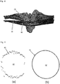
- Figure 3(a) shows the original RPE surface with typical artifacts in the in-between B-scans direction. These are corrected after applying our TPS approach, while keeping the shape of the original surface. The result is presented in Figure 3(b) .
- the ILM surface is determined, a correspondence between the RPE polygon mesh and the ILM polygon mesh is established. For further analysis it is necessary to find the corresponding points between these two surfaces. This process is demonstrated in the following. Vertices in the RPE surface corresponding to each face ( f i ⁇ F ilm
- i 0, ..., m ilm - 1) of the ILM surface are computed.
- the RPE surface represented here as a function graph: M rpe : R 2 ⁇ R , has a less complex structure compared to the ILM.
- the number of the A-scans (x-direction) and the number of the B-scans (y-direction) are fixed, which creates a regular XY-grid as a domain for the RPE graph function. Therefore, the index of each vertex of the RPE surface can be computed using the numbers of x-lines (vertical lines) and y-lines (horizontal lines) and the sampling size in both directions, denoted by ⁇ x and ⁇ y respectively.
- xline x max ⁇ x min ⁇ x + 1
- yline y max ⁇ y min ⁇ y + 1
- x max , x min , y max , and y min are the bounding values of the RPE surface in x and y directions.
- c ⁇ i represents the projected centroid.
- c ⁇ xi and c ⁇ yi are the corresponding x and y coordinates.
- ⁇ i represents the 3 x 3 neighborhood (at XY-plane) of vertex i.
- ⁇ i corresponds to the projection of vertex v i ⁇ V rpe onto XY-plane.
- c v i ⁇ R 3
- i 0 , ⁇ , m ilm ⁇ 1 which represents the set of RPE surface vertices corresponding to each face in F ilm .
- a visual representation of the correspondence computation is shown in Figure 6 , where the RPE's regular XY-grid is shown in blue and the projected ILM's vertices and edges are painted in
- BMO is the termination of the Bruch's membrane (BM) layer, i.e. the lower boundary of the RPE, and serves as a stable zero reference plane for ONH quantification.
- BM Bruch's membrane
- the BMO is an important parameter in the detection of ONH morphologic parameters.
- a challenge in BMO detection is the correct identification of these points 40, especially in the presence of shadows caused by blood vessels, or the border tissue of Elsching 50- a structure similar to the BM.
- the BMO points 40 are segmented in the three-dimensional image data directly without the use of a two-dimensional projection image in the XY-plane, as know from the state of the art.
- the image data are flattened. This step refers to the translation of all A-scans such that a chosen boundary in the volume is flat.
- the retina is aligned to the smoothed RPE lower . The alignment facilitates the volume reduction process, as well as the differentiation of BMO from other tissue.
- the end-points of the rough ONH area, A ONH provide the starting points for BMO points detection.
- the starting points are updated with new BMO points candidates if they meet the following conditions: 1) have minimum value in the 2D Morlet filtered image, 2) d(p new ,p BM0 _ seed ) ⁇ 30 ⁇ m, and 3) the curvature in a neighboring region of 5 voxels is almost zero to avoid including the tissue of Elsching.
- the BMO points detected in the left and right part of one B-scan overlap the BMO starting or end region previously defined by A ONH are updated accordingly.
- An example of a pair (left and right) detected BMO points is shown in Figure 2(f) .
- the BMO points Due to blood vessels around the ONH, noise components and three-dimensional OCT scan patterns, the BMO points are non-uniform and noisy as shown in Figure 5(a) . To remove these artifacts, an ellipse is fitted to the BMO points. Another key parameter in the ONH shape analysis is the center of the BMO points. This is computed as the barycenter of the all BMO points. Figure 5 shows that the ellipse fitting is not only removing the noise but also increases the data points uniformly.
- the region inside the BMO points is of special interest since BMO points represent the optic disc margin.
- the elliptic representation of the BMO points in R 2 i.e. the fitted ellipse, along with the barycenter of the BMO points are used.
- the centers of the ILM and the RPE surfaces corresponding to the center p ⁇ c of the BMO points are computed.
- min v ⁇ j ilm ⁇ p ⁇ c rpec j ⁇ 0 , ... , n rpe ⁇ 1
- the vertices v ilmc ⁇ V ilm and v rpec ⁇ V rpe represent the center of the ILM and the RPE surfaces, respectively.
- the ellipse is transformed into a circle using the affine transform.
- p ⁇ i e represents the fitted ellipse point to p ⁇ i
- p ⁇ i c denotes the corresponding affine transformed point on a circle of radius r. This transformation reduces the complexity of the BMO region computation and increases the speed of the method, particularly when implemented as a computer program.
- c ⁇ j ilm ⁇ v ⁇ ilmc ⁇ r , ⁇ rpe f j ⁇ F rpe
- the computation of the respective regions is done using the disk growing method.
- the central region of the ILM polygon mesh, the central region of the RPE polygon mesh as well as the BMO opening region are determined.
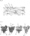
- the ONH cup is defined as a segment of the ILM surface 20, i.e. the ILM polygon mesh 20, particularly the central ILM region 25, which extends below the RPE surface 30 as shown in Figure 7(a) and (b) .
- the cup is not present in every ONH volume scan.
- the ILM surface is always above the RPE surface.
- To detect the presence of the ONH cup for each face f i ⁇ F ilm and compute its centroid c i . As mentioned above, each face f i of the ILM has the corresponding vertex v i ⁇ C in RPE.
- c i z ⁇ v i z ⁇ 0 for all faces in ILM, then, there is no cup available in the ONH region. Otherwise, there is a cup.
- the terms c i z and v i z show the corresponding z-coordinates (height).
- ⁇ cup f i ⁇ F ilm
- ⁇ cup consists of faces (triangles) of ILM, which are below the RPE surface.
- the cup region is also a manifold surface with proper face normal orientation. To compute the volume of the cup accurately, the face normal information at each triangle of the region can be used.
- a i 1 2 e ⁇ 0 ⁇ e ⁇ 1
- h i c i z ⁇ v i z
- e 0 and e 1 are the connected edges of the projected triangle.
- the cross product between the two edges will take care of the orientation of the corresponding face and enables a precise volume computation even in complex topological regions.
- CONHT Central ONH thickness
- the CONHT is defined as the height difference between the center of the ILM and the RPE surfaces as shown in Figure 7(c) .
- V bmo ⁇ f i ⁇ ⁇ bmo A i h i , where A i is area of the face f i which belongs to the set ⁇ bmo.
- h i is also computed using the corresponding vertices in the RPE surface.
- the ONH total volume is also computed using ILM and RPE surfaces.
- the total volume is computed from the circular region, with radius 1.5mm, centered at v ilmc and v rpec for ILM and RPE surfaces respectively, as shown in Figure 9(a) .
- c ⁇ j ilm ⁇ v ⁇ ilmc ⁇ 1.5 mm , ⁇ 1.5 mm rpe f j ⁇ F rpe
- the ONH annular region represents the ONH outer region, see Figure 9(c) .
- the volume of the annular region is computed using the ILM and RPE surfaces correspondence.
- V av ⁇ f i ⁇ ⁇ av A i h i .
- the annular region volume helps to see the change in the outer region of the ONH volume in different cohorts.
- the roughness on the ILM surface within the BMO region is an important parameter and commonly known as the bending energy on a manifold surface.
- the bending energy measures the fairness of a surface in terms of the curvature.
- the outer region of the ILM surface is quite smooth and flat unlike the one inside the BMO, which has very complex topological structure.
- the term a j is the area of the face f i .
- the corresponding eigenvector is denoted by e k .
- the dominant eigenvalue ⁇ 0 i has the corresponding eigenvector in the direction of the face normal and the remaining two eigenvectors will be aligned to the principle curvature direction on the ILM surface.
- ⁇ 0 i will be significant
- ⁇ 0 i and ⁇ 1 i will be significant and at the corners, all of these eigenvalues are significant.
- Equation 7(d) shows how each face of the BMO region is colored based on the bending energy. The color is scaled from white (flat regions) to dark (sharp features).
- BMO-MRW has been proposed by [6] as a valid alternative structural measure. It computes the minimum distance between the BMO points and the ILM surface.
- BMO-MRW surface area BMO-MRA
- BMO-MRA BMO-MRW surface area
- p i mrw v j ⁇ V ilm
- the MRW points P mrw p i mrw ⁇ R 3
- a A quad surface is created using point sets P e and P mrw by introducing edges between the corresponding vertices in both point sets and connecting the neighbor points.
- i 0, ..., n p - 1 ⁇ .
- the method according to the invention was also tested with several other scan protocols of the same device (ONH cube with 73 B-scans, scanning angle of 15° ⁇ 15° and resolution 384 A-scans per B-scan, spatial resolution in x direction is ⁇ 12.6 ⁇ m, in axial direction ⁇ 3.9 ⁇ m and the distance between two B-scans ⁇ 61 ⁇ m, ONH star scan with 24 B-scans, scanning angle of 15° x15° and a resolution of 768 A-scans per B-scan, spatial resolution in x direction is ⁇ 5.36 ⁇ m, in axial direction ⁇ 3.9 ⁇ m) and the volumetric ONH-centered protocol acquired using Cirrus HD OCT (Carl Zeiss Meditec, Dublin, CA), which covers 6 ⁇ 6 ⁇ 2 mm 3 region with 200 ⁇ 200 ⁇ 1024 voxels and obtained positive results.
- Cirrus HD OCT Carl Zeiss Meditec, Dublin, CA
- Table 1 Repeatability test for the 3D parameters. Abbreviations: ICC - intra-class correlation coefficient, LCI - lower boundary of 95% confidence interval and UCI - upper boundary of 95% confidence interval.
- Table 2 Mean ( ⁇ SD) unsigned error (pixels) Mean ( ⁇ SD) unsigned error ( ⁇ m) Mean ( ⁇ SD) signed error (pixels) Mean ( ⁇ SD) signed error ( ⁇ m) x axis 4.9098 ( ⁇ 4.9182) 61.8635 ( ⁇ 61.9693) -0.6107 ( ⁇ 6.9261) -7.6943 ( ⁇ 87.2693) z axis 2.8828 ( ⁇ 3.1801) 12.4024 ( ⁇ 11.2429) -0.3618 ( ⁇ 4.2790) -1.4110 ( ⁇ 16.6881)
- Table 2 Mean unsigned and signed error in pixel and ⁇ m, for the x axis, and z axis between automatic (proposed) and manual segmentation.
- results of the method according to the invention for 248 OCT scans are presented, from three groups, 71 healthy control eyes (HC), 31 eyes of patients suffering from idiopathic intracranial hypertension (IIH), which causes swelling of the ONH (papilledema).
- HC healthy control eyes
- IIH idiopathic intracranial hypertension
- NMOSD nueromyelitis spectrum disorder
- ON optic neuritis
- ONH volume In IIH patients, the ONH volume is increased and was shown to correlate with cerebrospinal fluid (CSF) pressure.
- CSF cerebrospinal fluid
- ON is one of the most common initial clinical presentations of MS without any prior history of a demyelinating event.
- acute ON affects 50%, 70% of MS patients.
- RNFL retinal nerve fiber layer
- Optic neuritis (ON) is the first NMOSD-related clinical event in 55% of the patients, which causes severe structural damage to the optic nerve and retina with resulting functional impairment.
- Recurrent ONs in NMOSD give rise to severely thinned pRNFL and combined ganglion cell layer and inner plexiform layer (GCIP).
- Table 3 Analysis of all the 3D parameters defined for the HC and patient group. The last column shows the GEE analysis between the two groups. Abbreviations: HC - healthy controls. SD - standard deviation, Min - minimum value, Max - maximum value, GEE - generalized estimating equation models analysis accounting for the inter-eye/intra-subject dependencies, p - p value.
- Fig. 8 it is exemplary shown in which region the Bruch's membrane can be seen in a OCT scan. Close to the optic nerve head, the RPE portion 3 ends and the Bruch's membrane 44 (underlined by a white bar) is visible as a continuation of the RPE 3. At the end points of the Bruch's membrane 44 the Bruch's membrane openings 43 are visible that can be identified as well by the method according to the invention.
- the border tissue of Elsching 50 is also visible in this OCT scan.
- the vitreous 51 is also indicated in this OCT-scan.
Landscapes
- Engineering & Computer Science (AREA)
- Health & Medical Sciences (AREA)
- Life Sciences & Earth Sciences (AREA)
- Physics & Mathematics (AREA)
- General Health & Medical Sciences (AREA)
- Medical Informatics (AREA)
- General Physics & Mathematics (AREA)
- Theoretical Computer Science (AREA)
- Animal Behavior & Ethology (AREA)
- Public Health (AREA)
- Veterinary Medicine (AREA)
- Biophysics (AREA)
- Ophthalmology & Optometry (AREA)
- Biomedical Technology (AREA)
- Heart & Thoracic Surgery (AREA)
- Molecular Biology (AREA)
- Surgery (AREA)
- Computer Vision & Pattern Recognition (AREA)
- Geometry (AREA)
- Nuclear Medicine, Radiotherapy & Molecular Imaging (AREA)
- Radiology & Medical Imaging (AREA)
- Software Systems (AREA)
- Computer Graphics (AREA)
- Signal Processing (AREA)
- Quality & Reliability (AREA)
- Eye Examination Apparatus (AREA)
- Image Processing (AREA)
- Image Analysis (AREA)
Priority Applications (7)
| Application Number | Priority Date | Filing Date | Title |
|---|---|---|---|
| EP18198717.3A EP3633604A1 (fr) | 2018-10-04 | 2018-10-04 | Procédé de quantification automatique de la forme d'une tête de nerf optique |
| EP19779043.9A EP3861524B1 (fr) | 2018-10-04 | 2019-10-04 | Procédé de quantification automatique de la forme d'une tête de nerf optique |
| PCT/EP2019/076935 WO2020070294A1 (fr) | 2018-10-04 | 2019-10-04 | Procédé de quantification de forme automatique d'une tête de nerf optique |
| ES19779043T ES2977594T3 (es) | 2018-10-04 | 2019-10-04 | Método para la cuantificación automática de la forma de una cabeza de nervio óptico |
| CA3114482A CA3114482A1 (fr) | 2018-10-04 | 2019-10-04 | Procede de quantification de forme automatique d'une tete de nerf optique |
| JP2021518516A JP2022513424A (ja) | 2018-10-04 | 2019-10-04 | 視神経乳頭の自動形状定量化の方法 |
| US17/282,386 US12161408B2 (en) | 2018-10-04 | 2019-10-04 | Method for automatic shape quantification of an optic nerve head |
Applications Claiming Priority (1)
| Application Number | Priority Date | Filing Date | Title |
|---|---|---|---|
| EP18198717.3A EP3633604A1 (fr) | 2018-10-04 | 2018-10-04 | Procédé de quantification automatique de la forme d'une tête de nerf optique |
Publications (1)
| Publication Number | Publication Date |
|---|---|
| EP3633604A1 true EP3633604A1 (fr) | 2020-04-08 |
Family
ID=63921489
Family Applications (2)
| Application Number | Title | Priority Date | Filing Date |
|---|---|---|---|
| EP18198717.3A Withdrawn EP3633604A1 (fr) | 2018-10-04 | 2018-10-04 | Procédé de quantification automatique de la forme d'une tête de nerf optique |
| EP19779043.9A Active EP3861524B1 (fr) | 2018-10-04 | 2019-10-04 | Procédé de quantification automatique de la forme d'une tête de nerf optique |
Family Applications After (1)
| Application Number | Title | Priority Date | Filing Date |
|---|---|---|---|
| EP19779043.9A Active EP3861524B1 (fr) | 2018-10-04 | 2019-10-04 | Procédé de quantification automatique de la forme d'une tête de nerf optique |
Country Status (6)
| Country | Link |
|---|---|
| US (1) | US12161408B2 (fr) |
| EP (2) | EP3633604A1 (fr) |
| JP (1) | JP2022513424A (fr) |
| CA (1) | CA3114482A1 (fr) |
| ES (1) | ES2977594T3 (fr) |
| WO (1) | WO2020070294A1 (fr) |
Cited By (2)
| Publication number | Priority date | Publication date | Assignee | Title |
|---|---|---|---|---|
| WO2022175945A1 (fr) * | 2021-02-16 | 2022-08-25 | Spring Vision Ltd. | Système et procédé de surveillance d'affections de la papille optique |
| EP4163870A1 (fr) * | 2021-10-05 | 2023-04-12 | Topcon Corporation | Appareil de diagnostic médical et procédé d'évaluation d'états pathologiques utilisant des données 3d et des images de lame criblée |
Citations (2)
| Publication number | Priority date | Publication date | Assignee | Title |
|---|---|---|---|---|
| WO2013148687A2 (fr) * | 2012-03-26 | 2013-10-03 | The Cleveland Clinic Foundation | Analyse volumétrique de pathologies |
| US20150157202A1 (en) | 2013-12-09 | 2015-06-11 | Alexander Ulrich Brandt | Method and System for Optic Nerve Head Shape Quantification |
Family Cites Families (2)
| Publication number | Priority date | Publication date | Assignee | Title |
|---|---|---|---|---|
| US7028899B2 (en) * | 1999-06-07 | 2006-04-18 | Metrologic Instruments, Inc. | Method of speckle-noise pattern reduction and apparatus therefore based on reducing the temporal-coherence of the planar laser illumination beam before it illuminates the target object by applying temporal phase modulation techniques during the transmission of the plib towards the target |
| US6988660B2 (en) * | 1999-06-07 | 2006-01-24 | Metrologic Instruments, Inc. | Planar laser illumination and imaging (PLIIM) based camera system for producing high-resolution 3-D images of moving 3-D objects |
-
2018
- 2018-10-04 EP EP18198717.3A patent/EP3633604A1/fr not_active Withdrawn
-
2019
- 2019-10-04 WO PCT/EP2019/076935 patent/WO2020070294A1/fr not_active Ceased
- 2019-10-04 EP EP19779043.9A patent/EP3861524B1/fr active Active
- 2019-10-04 US US17/282,386 patent/US12161408B2/en active Active
- 2019-10-04 JP JP2021518516A patent/JP2022513424A/ja active Pending
- 2019-10-04 ES ES19779043T patent/ES2977594T3/es active Active
- 2019-10-04 CA CA3114482A patent/CA3114482A1/fr active Pending
Patent Citations (2)
| Publication number | Priority date | Publication date | Assignee | Title |
|---|---|---|---|---|
| WO2013148687A2 (fr) * | 2012-03-26 | 2013-10-03 | The Cleveland Clinic Foundation | Analyse volumétrique de pathologies |
| US20150157202A1 (en) | 2013-12-09 | 2015-06-11 | Alexander Ulrich Brandt | Method and System for Optic Nerve Head Shape Quantification |
Non-Patent Citations (11)
| Title |
|---|
| A. S. C. REIS; N. O'LEARY; H. YANG ET AL.: "Influence of clinically invisible, but optical coherence tomography detected, optic disc margin anatomy on neuroretinal rim evaluation", INVESTIGATIVE OPHTHALMOLOGY & VISUAL SCIENCE, vol. 53, no. 4, 2012, pages 1852 - 1860 |
| B. J. ANTONY: "A Combined Machine-learning and Graph-based Framework for the 3-d Automated Segmentation of Retinal Structures in Sd-oct Images", PHD THESIS, 2013, pages AAI3608177 |
| C.-L. CHEN; H. ISHIKAWA; G. WOLLSTEIN ET AL.: "Individual a-scan signal normalization between two spectral domain optical coherence tomography devices", INVESTIGATIVE OPHTHALMOLOGY & VISUAL SCIENCE, vol. 54, no. 5, 2013, pages 3463 - 3471 |
| E. M. KADAS; F. KAUFHOLD; C. SCHULZ ET AL.: "3D Optic Nerve Head Segmentation in Idiopathic Intracranial Hypertension", 2012, SPRINGER BERLIN HEIDELBERG, pages: 262 - 267 |
| GIBSON E ET AL: "Optic Nerve Head Registration Via Hemispherical Surface and Volume Registration", IEEE TRANSACTIONS ON BIOMEDICAL ENGINEERING, IEEE SERVICE CENTER, PISCATAWAY, NJ, USA, vol. 57, no. 10, 1 October 2010 (2010-10-01), pages 2592 - 2595, XP011327056, ISSN: 0018-9294, DOI: 10.1109/TBME.2010.2060337 * |
| K. ROHR; H. S. STIEHL; R. SPRENGEL ET AL.: "Point-based elastic registration of medical image data using approximating thin-plate splines", 1996, SPRINGER BERLIN HEIDELBERG, pages: 297 - 306 |
| KYUNGMOO LEE ET AL: "Segmentation of the Optic Disc in 3-D OCT Scans of the Optic Nerve Head", IEEE TRANSACTIONS ON MEDICAL IMAGING, IEEE SERVICE CENTER, PISCATAWAY, NJ, US, vol. 29, no. 1, 1 January 2010 (2010-01-01), pages 159 - 168, XP011295733, ISSN: 0278-0062 * |
| LEE SIEUN ET AL: "Exact Surface Registration of Retinal Surfaces From 3-D Optical Coherence Tomography Images", IEEE TRANSACTIONS ON BIOMEDICAL ENGINEERING, IEEE SERVICE CENTER, PISCATAWAY, NJ, USA, vol. 62, no. 2, 1 February 2015 (2015-02-01), pages 609 - 617, XP011570452, ISSN: 0018-9294, [retrieved on 20150116], DOI: 10.1109/TBME.2014.2361778 * |
| M. D. ABRAMOFF ET AL: "Automated Segmentation of the Cup and Rim from Spectral Domain OCT of the Optic Nerve Head", INVESTIGATIVE OPHTHALMOLOGY & VISUAL SCIENCE, vol. 50, no. 12, 1 December 2009 (2009-12-01), pages 5778 - 5784, XP055049457, ISSN: 0146-0404, DOI: 10.1167/iovs.09-3790 * |
| M. K. GARVIN; M. D. ABRAMOFF; R. KARDON ET AL.: "Intraretinal layer segmentation of macular optical coherence tomography images using optimal 3d graph search", IEEE TRANSACTIONS ON MEDICAL IMAGING, vol. 27, 2008, pages 1495 - 1505, XP011226538, DOI: doi:10.1109/TMI.2008.923966 |
| S. LEE ET AL: "END-TO-END PIPELINE FOR FOURIER DOMAIN OPTICAL COHERENCE TOMOGRAPHY OF HUMAN OPTIC NERVE HEAD", CMBES, vol. 33, no. 1, 15 June 2010 (2010-06-15), XP055549128 * |
Cited By (3)
| Publication number | Priority date | Publication date | Assignee | Title |
|---|---|---|---|---|
| WO2022175945A1 (fr) * | 2021-02-16 | 2022-08-25 | Spring Vision Ltd. | Système et procédé de surveillance d'affections de la papille optique |
| EP4163870A1 (fr) * | 2021-10-05 | 2023-04-12 | Topcon Corporation | Appareil de diagnostic médical et procédé d'évaluation d'états pathologiques utilisant des données 3d et des images de lame criblée |
| US12272459B2 (en) | 2021-10-05 | 2025-04-08 | Topcon Corporation | Medical diagnostic apparatus and method for evaluation of pathological conditions using 3D data and images of lamina cribrosa |
Also Published As
| Publication number | Publication date |
|---|---|
| WO2020070294A1 (fr) | 2020-04-09 |
| US12161408B2 (en) | 2024-12-10 |
| EP3861524A1 (fr) | 2021-08-11 |
| US20210378502A1 (en) | 2021-12-09 |
| EP3861524C0 (fr) | 2024-02-14 |
| EP3861524B1 (fr) | 2024-02-14 |
| CA3114482A1 (fr) | 2020-04-09 |
| ES2977594T3 (es) | 2024-08-27 |
| JP2022513424A (ja) | 2022-02-08 |
Similar Documents
| Publication | Publication Date | Title |
|---|---|---|
| US7992999B2 (en) | Automated assessment of optic nerve head with spectral domain optical coherence tomography | |
| US9418423B2 (en) | Motion correction and normalization of features in optical coherence tomography | |
| Abràmoff et al. | Retinal imaging and image analysis | |
| JP6005663B2 (ja) | 血管画像における動静脈比の自動測定 | |
| Baroni et al. | Towards quantitative analysis of retinal features in optical coherence tomography | |
| Xiang et al. | Automatic retinal layer segmentation of OCT images with central serous retinopathy | |
| US11514574B2 (en) | Methods for detection and enhanced visualization of pathologies in a human eye | |
| JP2021529622A (ja) | 網膜の光干渉断層撮影画像のセグメンテーションの方法及びコンピュータプログラム | |
| CN106485721A (zh) | 从光学相干断层图像获取视网膜结构的方法及其系统 | |
| Khansari et al. | Automated deformation-based analysis of 3D optical coherence tomography in diabetic retinopathy | |
| CN103854284B (zh) | 基于三维图搜索浆液性色素上皮层脱离的视网膜分割方法 | |
| Yadav et al. | Optic nerve head three-dimensional shape analysis | |
| EP3861524B1 (fr) | Procédé de quantification automatique de la forme d'une tête de nerf optique | |
| Padmasini et al. | State-of-the-art of level-set methods in segmentation and registration of spectral domain optical coherence tomographic retinal images | |
| Lee et al. | 3-D segmentation of retinal blood vessels in spectral-domain OCT volumes of the optic nerve head | |
| Antony et al. | Automated 3D segmentation of intraretinal layers from optic nerve head optical coherence tomography images | |
| US10062164B2 (en) | Method for the analysis of image data representing a three-dimensional volume of biological tissue | |
| Saeedizadeh et al. | A device-independent, shape preserving retinal optical coherence tomography image alignment method applying TV-Unet for RPE layer detection | |
| Lee | Segmentations of the intraretinal surfaces, optic disc and retinal blood vessels in 3D-OCT scans | |
| Haleem et al. | Automatic extraction of optic disc boundary for detecting retinal diseases | |
| WO2025231055A1 (fr) | Procédé et appareil d'acquisition de données d'image ophtalmique et d'identification d'une maladie | |
| Hu | Multimodal 3-D segmentation of optic nerve head structures from spectral domain OCT volumes and color fundus photographs | |
| Muramatsu et al. | Detection of Eye Diseases | |
| Neetha et al. | A Two Stage Contour Evolution | |
| Antony | Automated 3-D segmentation of intraretinal surfaces from optical coherence tomography images centered on the optic nerve head |
Legal Events
| Date | Code | Title | Description |
|---|---|---|---|
| PUAI | Public reference made under article 153(3) epc to a published international application that has entered the european phase |
Free format text: ORIGINAL CODE: 0009012 |
|
| STAA | Information on the status of an ep patent application or granted ep patent |
Free format text: STATUS: THE APPLICATION HAS BEEN PUBLISHED |
|
| AK | Designated contracting states |
Kind code of ref document: A1 Designated state(s): AL AT BE BG CH CY CZ DE DK EE ES FI FR GB GR HR HU IE IS IT LI LT LU LV MC MK MT NL NO PL PT RO RS SE SI SK SM TR |
|
| AX | Request for extension of the european patent |
Extension state: BA ME |
|
| STAA | Information on the status of an ep patent application or granted ep patent |
Free format text: STATUS: THE APPLICATION IS DEEMED TO BE WITHDRAWN |
|
| 18D | Application deemed to be withdrawn |
Effective date: 20201009 |