EP3633687B1 - Elektrolyt für elektrochemische vorrichtung und herstellungsverfahren dafür - Google Patents
Elektrolyt für elektrochemische vorrichtung und herstellungsverfahren dafür Download PDFInfo
- Publication number
- EP3633687B1 EP3633687B1 EP18805568.5A EP18805568A EP3633687B1 EP 3633687 B1 EP3633687 B1 EP 3633687B1 EP 18805568 A EP18805568 A EP 18805568A EP 3633687 B1 EP3633687 B1 EP 3633687B1
- Authority
- EP
- European Patent Office
- Prior art keywords
- electrolyte
- electrode
- carbon quantum
- quantum dot
- metal
- Prior art date
- Legal status (The legal status is an assumption and is not a legal conclusion. Google has not performed a legal analysis and makes no representation as to the accuracy of the status listed.)
- Active
Links
Images







Classifications
-
- H—ELECTRICITY
- H01—ELECTRIC ELEMENTS
- H01B—CABLES; CONDUCTORS; INSULATORS; SELECTION OF MATERIALS FOR THEIR CONDUCTIVE, INSULATING OR DIELECTRIC PROPERTIES
- H01B1/00—Conductors or conductive bodies characterised by the conductive materials; Selection of materials as conductors
- H01B1/06—Conductors or conductive bodies characterised by the conductive materials; Selection of materials as conductors mainly consisting of other non-metallic substances
- H01B1/12—Conductors or conductive bodies characterised by the conductive materials; Selection of materials as conductors mainly consisting of other non-metallic substances organic substances
- H01B1/122—Ionic conductors
-
- H—ELECTRICITY
- H01—ELECTRIC ELEMENTS
- H01M—PROCESSES OR MEANS, e.g. BATTERIES, FOR THE DIRECT CONVERSION OF CHEMICAL ENERGY INTO ELECTRICAL ENERGY
- H01M10/00—Secondary cells; Manufacture thereof
- H01M10/05—Accumulators with non-aqueous electrolyte
- H01M10/052—Li-accumulators
- H01M10/0525—Rocking-chair batteries, i.e. batteries with lithium insertion or intercalation in both electrodes; Lithium-ion batteries
-
- H—ELECTRICITY
- H01—ELECTRIC ELEMENTS
- H01M—PROCESSES OR MEANS, e.g. BATTERIES, FOR THE DIRECT CONVERSION OF CHEMICAL ENERGY INTO ELECTRICAL ENERGY
- H01M10/00—Secondary cells; Manufacture thereof
- H01M10/05—Accumulators with non-aqueous electrolyte
- H01M10/056—Accumulators with non-aqueous electrolyte characterised by the materials used as electrolytes, e.g. mixed inorganic/organic electrolytes
- H01M10/0564—Accumulators with non-aqueous electrolyte characterised by the materials used as electrolytes, e.g. mixed inorganic/organic electrolytes the electrolyte being constituted of organic materials only
- H01M10/0565—Polymeric materials, e.g. gel-type or solid-type
-
- H—ELECTRICITY
- H01—ELECTRIC ELEMENTS
- H01M—PROCESSES OR MEANS, e.g. BATTERIES, FOR THE DIRECT CONVERSION OF CHEMICAL ENERGY INTO ELECTRICAL ENERGY
- H01M10/00—Secondary cells; Manufacture thereof
- H01M10/05—Accumulators with non-aqueous electrolyte
- H01M10/056—Accumulators with non-aqueous electrolyte characterised by the materials used as electrolytes, e.g. mixed inorganic/organic electrolytes
- H01M10/0564—Accumulators with non-aqueous electrolyte characterised by the materials used as electrolytes, e.g. mixed inorganic/organic electrolytes the electrolyte being constituted of organic materials only
- H01M10/0566—Liquid materials
- H01M10/0568—Liquid materials characterised by the solutes
-
- G—PHYSICS
- G02—OPTICS
- G02F—OPTICAL DEVICES OR ARRANGEMENTS FOR THE CONTROL OF LIGHT BY MODIFICATION OF THE OPTICAL PROPERTIES OF THE MEDIA OF THE ELEMENTS INVOLVED THEREIN; NON-LINEAR OPTICS; FREQUENCY-CHANGING OF LIGHT; OPTICAL LOGIC ELEMENTS; OPTICAL ANALOGUE/DIGITAL CONVERTERS
- G02F1/00—Devices or arrangements for the control of the intensity, colour, phase, polarisation or direction of light arriving from an independent light source, e.g. switching, gating or modulating; Non-linear optics
- G02F1/01—Devices or arrangements for the control of the intensity, colour, phase, polarisation or direction of light arriving from an independent light source, e.g. switching, gating or modulating; Non-linear optics for the control of the intensity, phase, polarisation or colour
- G02F1/15—Devices or arrangements for the control of the intensity, colour, phase, polarisation or direction of light arriving from an independent light source, e.g. switching, gating or modulating; Non-linear optics for the control of the intensity, phase, polarisation or colour based on an electrochromic effect
- G02F1/1514—Devices or arrangements for the control of the intensity, colour, phase, polarisation or direction of light arriving from an independent light source, e.g. switching, gating or modulating; Non-linear optics for the control of the intensity, phase, polarisation or colour based on an electrochromic effect characterised by the electrochromic material, e.g. by the electrodeposited material
- G02F1/1523—Devices or arrangements for the control of the intensity, colour, phase, polarisation or direction of light arriving from an independent light source, e.g. switching, gating or modulating; Non-linear optics for the control of the intensity, phase, polarisation or colour based on an electrochromic effect characterised by the electrochromic material, e.g. by the electrodeposited material comprising inorganic material
- G02F1/1525—Devices or arrangements for the control of the intensity, colour, phase, polarisation or direction of light arriving from an independent light source, e.g. switching, gating or modulating; Non-linear optics for the control of the intensity, phase, polarisation or colour based on an electrochromic effect characterised by the electrochromic material, e.g. by the electrodeposited material comprising inorganic material characterised by a particular ion transporting layer, e.g. electrolyte
-
- G—PHYSICS
- G02—OPTICS
- G02F—OPTICAL DEVICES OR ARRANGEMENTS FOR THE CONTROL OF LIGHT BY MODIFICATION OF THE OPTICAL PROPERTIES OF THE MEDIA OF THE ELEMENTS INVOLVED THEREIN; NON-LINEAR OPTICS; FREQUENCY-CHANGING OF LIGHT; OPTICAL LOGIC ELEMENTS; OPTICAL ANALOGUE/DIGITAL CONVERTERS
- G02F2202/00—Materials and properties
- G02F2202/36—Micro- or nanomaterials
-
- H—ELECTRICITY
- H01—ELECTRIC ELEMENTS
- H01M—PROCESSES OR MEANS, e.g. BATTERIES, FOR THE DIRECT CONVERSION OF CHEMICAL ENERGY INTO ELECTRICAL ENERGY
- H01M2300/00—Electrolytes
-
- H—ELECTRICITY
- H01—ELECTRIC ELEMENTS
- H01M—PROCESSES OR MEANS, e.g. BATTERIES, FOR THE DIRECT CONVERSION OF CHEMICAL ENERGY INTO ELECTRICAL ENERGY
- H01M2300/00—Electrolytes
- H01M2300/0017—Non-aqueous electrolytes
- H01M2300/0025—Organic electrolyte
-
- H—ELECTRICITY
- H01—ELECTRIC ELEMENTS
- H01M—PROCESSES OR MEANS, e.g. BATTERIES, FOR THE DIRECT CONVERSION OF CHEMICAL ENERGY INTO ELECTRICAL ENERGY
- H01M2300/00—Electrolytes
- H01M2300/0085—Immobilising or gelification of electrolyte
-
- H—ELECTRICITY
- H10—SEMICONDUCTOR DEVICES; ELECTRIC SOLID-STATE DEVICES NOT OTHERWISE PROVIDED FOR
- H10K—ORGANIC ELECTRIC SOLID-STATE DEVICES
- H10K50/00—Organic light-emitting devices
- H10K50/10—OLEDs or polymer light-emitting diodes [PLED]
- H10K50/11—OLEDs or polymer light-emitting diodes [PLED] characterised by the electroluminescent [EL] layers
- H10K50/135—OLEDs or polymer light-emitting diodes [PLED] characterised by the electroluminescent [EL] layers comprising mobile ions
-
- Y—GENERAL TAGGING OF NEW TECHNOLOGICAL DEVELOPMENTS; GENERAL TAGGING OF CROSS-SECTIONAL TECHNOLOGIES SPANNING OVER SEVERAL SECTIONS OF THE IPC; TECHNICAL SUBJECTS COVERED BY FORMER USPC CROSS-REFERENCE ART COLLECTIONS [XRACs] AND DIGESTS
- Y02—TECHNOLOGIES OR APPLICATIONS FOR MITIGATION OR ADAPTATION AGAINST CLIMATE CHANGE
- Y02E—REDUCTION OF GREENHOUSE GAS [GHG] EMISSIONS, RELATED TO ENERGY GENERATION, TRANSMISSION OR DISTRIBUTION
- Y02E60/00—Enabling technologies; Technologies with a potential or indirect contribution to GHG emissions mitigation
- Y02E60/10—Energy storage using batteries
Definitions
- the present invention relates to electrolyte for an electrochemical device and preparation method thereof, more particularly to electrolyte comprising a salt of a carbon quantum dot anion and a metal cation having an average diameter in the range of 2 to 12 nanometers (nm) and a surface charge of -20 mV or less, applied to an electrochemical device having a first electrode, a second electrode spaced apart from the first electrode and the electrolyte filled between the first electrode and the second electrode; and preparation method thereof.
- an electrolyte refers to a substance that imparts electrical conductivity to a solution and assists charge transfer during an electrochemical reaction.
- the electrolyte allows for the formation of a resistive contact between the electrode and the solution through the flow of ions and ion exchange, which is an essential component for the operation of the electrochemical device.
- the electrolyte does not participate in the oxidation / reduction reaction directly, but supports the electrochemical reaction.
- the electrolyte is generally in the form of a salt, which is usually used in a liquid by dissolving it in a solvent or gel form, but in some cases, it can be also dispersed in a solid.
- the conventional electrochemical device has a problem in terms of stability because the electrode material constituting the internal electrode is in contact with the electrolyte and the reversibility of insertion and desorption of ions (H +, Li +, etc.) is broken.
- organic solvents are used in many cases.
- Organic solvents have stability problems such as ignition, evaporation, and leakage.
- solid state electrolytes are more stable than liquid electrolytes, but exhibit low ionic conductivity and have problems such as increased interfacial contact resistance and deterioration of devices.
- LiPF 6 is mainly used as an electrolyte in lithium ion batteries because LiPF 6 has excellent overall physical properties such as ion mobility, ion pair dissociation, solubility, and SEI formation than the other electrolytes.
- LiPF 6 has problems such as poor thermal stability and side reactions even with a small amount of water.
- the following side reactions accelerate the continuous decomposition of the electrolyte and induce the gas to inflate the battery and lead to explosion.
- Electrochromic device refers to a device that changes the light transmittance characteristics by changing the color of the electrochromic material due to the redox reaction in response to the application of an electric field.
- the most successful products are a rear view mirror of the car that automatically adjusts the glare of the light at the rear at night, and a smart window, a window that can be automatically adjusted according to the light intensity.
- the smart window changes to a darker color tone to reduce the amount of light in sunny day, whereas it changes to a lighter color tone on a cloudy day, which makes the energy saving efficiency excellent.
- the application of the ECD in display such as an electronic board (e-book), etc. is continuously developing.
- the constitution of ECD is similar to that of a battery system.
- ECD have an electrochromic layer (anode) / electrolyte (Li +, H +) / relative electrode layer (cathode).
- electrochromic layer anode
- electrolyte Li +, H +
- relative electrode layer cathode
- the electrochromic layer WxOy, MoxOy, etc.
- the positive electrode layer VxOy, NixOy, etc.
- the cations such as Li + and H + and electrons are released from it, and becomes transparent when injected into that.
- the electrochromic layer constituting the ECD is divided into a reducing coloring material and an oxidizing coloring material.
- the reducing coloring material for example tungsten oxide, is a material that is colored when obtaining electrons.
- the oxidative coloring material is a material that is colored when the electrons are lost, and representative examples thereof include nickel oxide and cobalt oxide.
- representative electrochromic materials include inorganic metal oxides such as V 2 O 5 , Ir(OH) x , NiO x H y , TiO 2 , and MoO 3 ,; conductive polymers such as PEDOT (poly-3,4-ethylenedioxythiophene), polypyrrole, polyaniline, polyazulene, polythiophene, polypyridine, polyindole, polycarbazole, polyazine and polyquinone,; and organic coloring materials such as viologen, anthraquinone and phenocyazine.
- PEDOT poly-3,4-ethylenedioxythiophene
- polypyrrole polyaniline
- polyazulene polythiophene
- polypyridine polyindole
- polycarbazole polyazine and polyquinone
- organic coloring materials such as viologen, anthraquinone and phenocyazine.
- the ion storage medium must be formed on the counter electrode and the electrolyte must be included between the two electrodes to complete the electric circuit of the ECD. Therefore, in order to realize a high efficiency, high stability of the ECD, it is necessary to improve the electrochemical properties of the electrolyte, the color change material, and the ion storage medium as well as the structure of the ECD. In the case of the ECD and the electroluminescent device, chelate complexes formation of the anion of the electrolyte with the color change material or the light emitting material reduce the reliability of the electrochemical device. In order to remedy these shortcomings, large complex anion structures and organic ligand anion structures are attracting attention.
- tungsten oxide which has been studied extensively as an electrochromic material, causes irreversible chemical reaction with lithium ions embedded in an ECD, so that lithium ions are trapped in each layer of the ECD, and thus, each layer of the ECD is decomposed, splits into thin layers, and deteriorates the characteristics of the electrochromic device, and it can be deformed into a material that can no longer electrochromate or cause an electric leakage of the device, thereby losing its function as an electrochromic device.
- This electrolyte is self-suspended to provide a homogeneous fluid, wherein the PEG oligomers simultaneously act as a suspension medium for the nanoparticle core and as an ion-conducting network for lithium ion transport.
- WO2010 / 083041 also discloses a NOHM based hybrid electrolyte comprising a polymer corona doped with a lithium salt, a polymer corona attached to an inorganic nanoparticle core. Chaefer, J.L. et al. (J. Mater.
- Chem., 2011, 21, 10094 also disclosed Si02 nanoparticle hybrid electrolyte covalently binding to dense brushes of oligo-PEG chains doped with lithium salts, in particular lithium bis (trifluoromethanesulfonimide).
- This electrolyte is made from polyethylene glycol dimethylether (PEGDME) and provides good ion conductivity.
- PEGDME polyethylene glycol dimethylether
- the negative ions of lithium salts move freely through the electrolyte, and two-thirds of the current is carried by the negative ions, resulting in high polarization, thus causing internal resistance and voltage losses.
- Nanoparticulate organic hybrid materials are disclosed, characterized in that having a nanoparticulate organic containing inorganic nanoparticles covalently grafted with one or more anions of organic sodium salt or organic lithium salt through a linker group as bellows;
- Np represents an inorganic nanoparticle
- L is a linker group selected from a C1-C6 alkylene group and a phenyl-C1-C4-alkylene group
- X+ is sodium or lithium cation.
- 10-2011-0003505 disclosed an electrolyte comprising a solvent having chemical structure like bellows; (wherein X is C, N, O or aryl having substituent on aryl ring, provided that R 2 does not exist when X is a nitrogen, both R 1 and R 2 does not exist when X is an oxygen, and when R is an aryl group, none of R 1 , R 2 and R 5 are present; R 1 is a hydrogen atom or a carbon-based group; R 2 is a hydrogen atom or a carbon-based group; R 3 is a hydrogen atom or a carbon-based group; R4 and R5 are individually selected from hydrogen atoms or carbon-based groups, or R4 and R5 together form a carbon-based group to give a ring structure.); and a mixture comprising ionizable materials forming a solution with the solvent, characterized by solvating a polymer in the mixture.
- the electrolytes for the conventional ECD including the above-mentioned document are deteriorated due to its weak durability, the anion and/or cation of the electrolyte constituting the ionic salt react with the material constituting the electrochemical device (electrode, material participating in the oxidation / reduction reaction) reduces the durability of the electrochemical device.
- the ionic conductivity of the electrolyte can be expressed as the charge amount ⁇ mobility.
- the charge amount is low, the ionic conductivity is lowered. This means that the resistance of the electrochemical device is increased. If the applied voltage is increased or the ion salt concentration is increased to overcome this resistance, the durability of the device is deteriorated.
- LiPF 6 one of the lithium salts commonly used, shows that the fluorine of the hexafluorophosphate anion reacts with water to generate hydrogen fluoride (HF ) or precipitation such as or LiF, which is one of the important factors that lower the reliability and stability of the lithium secondary battery.
- the commercialized lithium ion battery is known to be difficult to be used as a large-scale power storage device due to the scarcity of lithium resources and the resulting cost increase.
- the formation of dendrites of lithium metal in batteries has a problem of stability causing internal overheating and/or combustion.
- metal cations such as sodium (Na + ), potassium (K + ), and magnesium (Mg 2+ ).
- Na + sodium
- K + potassium
- Mg 2+ magnesium
- the properties for the new electrolyte is required to be inflammable, non-volatile, non-toxic, etc. for safety in use and after disposal.
- Typical materials used in the preparation of polymers, polymer composites, hybrids, gels, ionic liquids, ceramics or solid electrolytes are inorganic matrices derived from nanoparticle oxides such as ⁇ -alumina and such as Nasicon and silicon dioxide. It may be a simple lithium halide with improved grain boundaries defects or sulfide glass in a SiS 2 + Li 2 S + Lil system.
- SiS 2 + Li 2 S + Lil system due to the low ion conductivity ( ⁇ 10 -4 S / cm) and low energy density of gels and solid electrolytes, they are not widely commercially available.
- magnesium (Mg) secondary batteries one of the next generation ion battery candidate, is paid attention due to high energy density/high output and not-forming dendritic growth on the electrode surface during the charging / discharging process.
- magnesium cathode is incompatible with conventional inorganic ionic salts.
- unavoidable volume changes in operation, which may causes stress and cracking in the electrolyte.
- an organic polymer matrix in electrolyte.
- Typical polymer examples may include polyethylene oxide, polypropylene oxide or polyethyleneimine and copolymers thereof. These materials are used in combination with suitable lithium salts such as lithium bis (trifluoromethanesulfonyl imide [Li (CF3S02) 2N](LiTFSI), and lithium tetrafluoroborate (LiBF4).
- suitable lithium salts such as lithium bis (trifluoromethanesulfonyl imide [Li (CF3S02) 2N](LiTFSI), and lithium tetrafluoroborate (LiBF4).
- Li (CF3S02) 2N](LiTFSI) lithium bis (trifluoromethanesulfonyl imide
- LiBF4 lithium tetrafluoroborate
- ⁇ and D are defined as conductivity and diffusion coefficient of each charged species, respectively.
- US 5,569,560 disclosed the use of an anionic complexing agent comprising a polyamine with a strong electron-removing unit CF 3 S0 2 attached in order to slow the anion, whereby lithium cations are used on a larger scale in electrochemical cells.
- an anionic complexing agent comprising a polyamine with a strong electron-removing unit CF 3 S0 2 attached in order to slow the anion, whereby lithium cations are used on a larger scale in electrochemical cells.
- the effect on the transport rate t + is negligible.
- solvent-free hybrid electrolytes based on nanoscale organic / silica hybrid materials (NOHM) with lithium salts have been developed( Nugent, JL et al, Adv. Mater., 2010, 22, 3677 ; Lu, Y. et al, J. Mater. Chem., 2012, 22, 4066 ).
- This electrolyte has a nanoparticle core bonded to polyethylene glycol (PEG) chain.
- PEG polyethylene glycol
- This electrolyte is self-suspended to provide a homogeneous fluid, wherein the PEG oligomers act as a suspension medium for the nanoparticle core and as an ion-conducting network for lithium ion transport simultaneously.
- WO2010 / 083041 also discloses a NOHM based hybrid electrolyte comprising a polymer corona doped with a lithium salt, a polymer corona attached to an inorganic nanoparticle core. Chaefer, J.L. et al. (J. Mater.
- Chem., 2011, 21, 10094 also disclosed Si0 2 nanoparticle hybrid electrolyte covalently binding to dense brushes of oligo-PEG chains doped with lithium salts, in particular lithium bis (trifluoromethanesulfonimide).
- This electrolyte is made from polyethylene glycol dimethylether (PEGDME) and provides good ion conductivity.
- PEGDME polyethylene glycol dimethylether
- the negative ions of lithium salts move freely through the electrolyte, and two-thirds of the current is carried by the negative ions, resulting in high polarization, thus causing internal resistance and voltage losses.
- Korean Patent Laid-Open Publication No. 10-2015-0052008 discloses nanoparticulate organic hybrid materials comprising inorganic nanoparticles covalently grafted with one or more anions of an organic sodium salt or an organic lithium salt via a linker group.
- a paper has been published that reports supercapacitance characteristics using graphene quantum dots as an electrolyte ("Graphene quantum dots as the electrolyte for solid state supercapacitors" (Sci. Rep., 2015, 6, 19292 )).
- graphene quantum dots as the electrolyte for solid state supercapacitors
- CN 106 129 469 discloses a composite solid polymer electrolyte and a preparation method thereof.
- the polymer electrolyte comprises a high-molecular polymer, carbon quantum dots and an organic lithium salt or organic sodium salt, wherein the high-molecular polymer is selected from one of polyoxyethylene, polyacrylonitrile or polymethyl methacrylate and the like.
- the preparation method comprises the steps of preparing the carbon quantum dots from organic ketone or organic aldehyde as a raw material and then compounding the carbon quantum dots and high-molecular polymer matrix and the organic lithium / sodium salt.
- GQDs graphene quantum dots
- GQDs are expected to be suitable for various applications.
- mass production is critically required.
- many methods for preparing GQDs with good properties and high yield have been introduced. The main synthesis strategies are known as bottom-up and top-down methods. Synthesis of GQDs from small organic molecules, known as the bottom-up approach, is appropriate for controlling the size of GQDs but requires multistep organic reactions and purification at each step.
- E. Hwang et. al., An Electrolyte-Free Flexible Electrochromic Device Using Electrostatically Strong Graphene Quantum Dot-Viologen Nanocomposites, Adv. Mater. 2014, 26, 5129-5736 discloses a strong electrostatic MV 2+ -GQD nanocomposite that provides an electrolyte-free flexible electrochromic device with high durability.
- the positively charged MV 2+ and negatively charged GQD are strongly stabilized by non-covalent intermolecular forces (e.g., electrostatic interactions, ⁇ - ⁇ stacking interactions, and cation- ⁇ electron interactions), eliminating the need for an electrolyte.
- An electrolyte-free flexible electrochromic device fabricated from the GQD-supported MV 2+ exhibits stable performance under mechanical and thermal stresses.
- the object of the present invention is to provide an electrolyte for an electrochemical device having an electrode on which the redox reaction occurs that can prevent decomposition or deformation of the electrode material or ionic salt, so that deterioration of the electrochemical device stability and performance can be prevented, electrochemical durability can be improved and the efficiency and performance of the electrochemical device can be improved, manufacturing method thereof and an electrochemical device comprising the electrolyte.
- the present invention provides an electrolyte for an electrochemical device including a first electrode, a second electrode spaced apart from the first electrode and an electrolyte filled between the first electrode and the second electrode, wherein the electrolyte comprises a salt form of a carbon quantum dot anion and a metal cation having an average diameter in the range of 2 to 12 nanometers (nm) and a surface potential of -20 mV or less.
- the present invention also provides an electrolyte for electrochemical device, characterized in that the metal is an alkali metal, alkaline earth metal or transition metal.
- the present invention also provides an electrolyte for an electrochemical device, characterized in that the metal is at least one selected from the group consisting of Li, Na, K, Mg and Zn.
- the present invention also provides an electrolyte for an electrochemical device, characterized in that a reversible electrochemical redox reaction occurs in at least one of the first electrode and the second electrode.
- the present invention provides an electrolyte for an electrochemical device, characterized in that the electrochemical device is one selected from the group consisting of a secondary battery, a solar cell, an electrochromic device and an electroluminescent device.
- the present invention provides an electrolyte for an electrochemical device, characterized in that the secondary battery is a lithium ion battery or a lithium polymer battery.
- the present invention provides a method for preparation of an electrolyte for an electrochemical device comprising the step of i) mixing the carbon precursor and the acid and hydrothermally synthesizing in the range of 80 to 120 °C to produce a carbon quantum dot having an average diameter in the range of 2 to 12 nanometers (nm) and the surface potential of -20mV or less, ; ii) preparing a carbon quantum anion-metal cation salt by reacting the carbon quantum dot with a metal ion; iii) removing the reaction impurities and; iv) classifying the carbon quantum dot ionic compounds according to size.
- the present invention also provides a method for preparation of an electrolyte for an electrochemical device, characterized in that the metal is an alkali metal, alkaline earth metal or transition metal.
- the present invention provides a method for preparation of an electrolyte for an electrochemical device, characterized in that the metal is at least one selected from the group consisting of Li, Na, K, Mg and Zn.
- the electrolyte for an electrochemical device according to the present invention has a very small dissociation energy of anion and a cation, and thus improves ionic conductivity. Due to large ion polarization, and high anionic thermochemical / electrochemical stability, no side reactions occur during device driving, it is possible to build an electrochemical device with greatly improving the stability and reliability.
- the term 'electrochemical device' refers to a device comprising a first electrode, a second electrode spaced apart from the first electrode and forming an electrically opposite to the first electrode, and electrolyte filled between the first electrode and the second electrode, wherein an electrochemical reaction is performed and a reversible electrochemical redox reaction occurs at the one or both of the first electrode and the second electrode.
- the term 'carbon quantum dot' refers to a quantum dot in the form of graphite oxide having at least one oxygen functional group capable of becoming anions on the surface and / or the edge thereof and having an average diameter in the range of 2 to 12 nm and the surface potential of -20mV or less; or quantum dots derivatives produced by reacting the quantum dot with polymerizable group.
- the term 'carbon quantum dot anion' refers to a carbon quantum dot of the oxygen functional group anionized.
- the first electrode may be a working electrode or an anode
- the second electrode forming an electrically opposite of the first electrode may be a counter electrode or a cathode.
- the electrochemical device of the present invention comprises a first electrode (working electrode), a second electrode (counter electrode) spaced from the first electrode and a electrolyte filled between the first electrode and the second electrode.
- the electrochemical device of the present invention may be any electrochemical device, such as an electrochromic device, an electrochemical light emitting device, a secondary battery or a solar cell, that reversibly undergoes an electrochemical redox reaction at a working electrode (material) or a cathode.
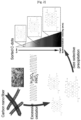
- FIG. 1 (a) is the electron microscope image and a schematic diagram of the structure of the carbon quantum dot ionic compound, (b) is a graph showing the absorption and emission profiles of the carbon quantum dot ionic compound of an electrolyte for an electrochemical device according to the present invention and FIG. 2 is a schematic diagram for explaining a manufacturing process of a carbon quantum dot for preparation of an electrolyte for an electrochemical device of the present invention.
- the carbon quantum dot ionic compound electrolyte of the present invention is a metal salt compound of a carbon quantum dot polyvalent anion and a metal cation in which the carbon quantum dot anion and the metal cation are paired.
- the carbon quantum dot anion of the present invention has a form of a polyanionic (A n- ), aromatic ring structure inside and oxygen functional groups on the surface and edge.
- the carbon quantum dot anion is combined with a metal cation to form a salt type ionic compound.
- the electrolyte for an electrochemical device of the present invention including the carbon quantum dot ionic compound is expected as follows; 1) Due to the surface negative charges, ionic bonds with various metal cations such as alkali metals, alkaline earth metals, and transition metals are possible. 2) Large size and large surface charges, which have a large polarity and low lattice energy. 3) Delocalization of the electron cloud is large due to resonance of the internal structure.
- the carbon quantum dot ionic compound of the present invention is not only easy to disperse in aqueous solutions and non-aqueous solvents, but also relatively free of mixing with organic solvents having low viscosity, low volatility, and high permittivity. Through above mentioned characteristics, the electrolyte of the present invention is deemed to have a high ionic conductivity.
- the metal cation may be an alkali metal, an alkaline earth metal or a transition metal cation, and examples thereof may be Li, Na, K, Mg, or Zn.
- the carbon quantum dot ionic compound can be used in liquid, gel, solid form, and it is possible to adjust the appropriate content thereof according to the concrete usage.
- the carbon quantum dot ionic compound may form an organic-inorganic complex by reacting with a derivative compound.
- the derivative compound is not particularly limited and may be any compound capable of inducing polymerization.
- a silane compound may be added to the prepared carbon quantum dot ionic compound, and a gel electrolyte may be prepared using a thermal crosslinking method.
- the carbon quantum dot used in the preparation of the electrolyte for an electrochemical device of the present invention has an average diameter in the range of 2 to 12 nm, more preferably in the range of 5 to 8 nm, an oxygen functional group being capable of an anion on the surface and / or the edge thereof, and a surface potential of less than or equal to -20mV. If the average diameter of the carbon quantum dot is less than 2nm, the carbon quantum dot anion is moved to the anode by the potential formed on the electrode of the electrochemical device, which decreases the t + (ion transport number), resulting in a decrease in the efficiency of the electrochromic device and it will reduce the lattice energy of the carbon quantum dot resulting in ionic conductivity reduction.
- the electrochromic device when the average diameter of carbon quantum dots is 12 nm or more, the ⁇ - ⁇ interaction between the carbon quantum dots increases, which causes aggregation and crystallization of carbon quantum dots in the electrochemical device and degrade the reliability of the device.
- pH control is adjusted according to the characteristics of the electrochemical device. For example, in the case of an electrochromic device to which a Prussian blue material is applied, when the pH of the electrolyte solution is 5 or more, the electrochromic device may be disordered due to deformation of the color change material.
- an electrolyte for an electrochemical device should have acid and basic resistance at the same time.
- the electrolyte for an electrochemical device of the present invention has a strong resistance not only to acids but also to base, so that there are very few restrictions on the use environment. Owing to this excellent chemical resistance, the electrolyte of the present invention is also suitable for bio experiments.
- FIG. 2 is a schematic diagram for explaining a manufacturing process of a carbon quantum dot for preparation of an electrolyte for an electrochemical device of the present invention.
- the preparation method of electrolyte for the electrochemical device of the present invention comprises the steps of i) mixing the carbon precursor and the acid and hydrothermally synthesizing in the range of 80 to 120 °C to produce a carbon quantum dot having an average diameter in the range of 2 to 12 nanometers (nm) and the surface potential of -20mV or less, ; ii) preparing a carbon quantum anion-metal cation salt by reacting the carbon quantum dot with a metal ion; iii) removing the reaction impurities and; iv) classifying the carbon quantum dot ionic compounds according to size.
- the preparation method of the present invention comprises the steps of i) mixing the carbon precursor and the acid and hydrothermally synthesizing in the range of 80 to 120 °C to produce a carbon quantum dot having an average diameter in the range of 2 to 12 nanometers (nm) and the surface potential of -20mV or less.
- step I) of the present invention is supposed to be well known as carbon quantum dot manufacturing method to a skilled person in the art, it will not be described in detail further herein. However, in this step, the inventors of the present invention have found that the carbon quantum dot properties (size, surface charge value) can be adjusted by varying the reaction temperature.
- the surface charges are -17, -23, and -28 mV, respectively, and the average diameters of the carbon quantum dot are 10, 8, and 5.5 nm, respectively.
- the preparation method of electrolyte of the present invention comprises the step of ii) preparing a carbon quantum anion-metal cation salt by reacting the carbon quantum dot with a metal ion.
- the source of the metal ions is not particularly limited, only if a metal salts showing predetermined solubility in aqueous solution, for example, metal hydroxides and metal carbonates, may be used.
- concrete sources of the metal ions include potassium hydroxide, sodium hydroxide, lithium hydroxide, cesium hydroxide, potassium carbonate and the like.
- the metal cation present in the carbon quantum dot anion can be selected according to the type and amount of the metal cation precursor to be added, and the pH and concentration of the solution can be adjusted.
- the preparation method of electrolyte for an electrochemical device of the present invention comprises the step of iii) removing the reaction impurities. After ii) step reaction, it is necessary to remove impurities such as unreacted carbon precursor from the solution.
- the removal of impurities is not particularly limited, in the embodiment of the present invention, the fractional crystallization or fractional precipitation is used.
- a water-soluble organic solvent ethanol, methanol
- white solid masses precipitate in this process In order to take only the supernatant, the solution was treated 30 minutes using an ultracentrifuge at 13,000 RPM. Repeat above steps 2 to 3 times to remove impurities by taking only the supernatant until no longer precipitation is produced.
- the carbon quantum dot anion-metal cation ion compound obtained is classified according to size.
- the classification technique of the carbon quantum dot ionic compound by size is not particularly limited, and in the exemplary embodiment of the present invention, a carbon quantum dot ionic compound having a specific molecular weight or size is obtained by using dialysis. Through above process, a carbon quantum dots ionic compound dispersed in an organic solvent can be prepared as well as an aqueous solution. The size and metal cation concentration of the finally obtained carbon quantum anion-metal cation ion compound were confirmed using transmission electron microscope and inductively coupled plasma (ICP), respectively.
- ICP inductively coupled plasma
- Electrolyte of the present invention can be dissolved in water-soluble solvents (methanol, ethanol), non-aqueous solvents (acetonitrile, dimethyl carbonate, ethylene carbonate), and an aqueous solution and used in the liquid phase, optionally dispersed in a suitable dispersion medium / matrix dispersed as a gel form.
- water-soluble solvents methanol, ethanol
- non-aqueous solvents acetonitrile, dimethyl carbonate, ethylene carbonate
- an aqueous solution and used in the liquid phase, optionally dispersed in a suitable dispersion medium / matrix dispersed as a gel form.
- FIG. 3 is the result of measuring the surface charge of the carbon quantum dot obtained by the reaction temperature. As shown in Fig.
- the surface charges of carbon quantum dots prepared at the respective temperatures are -17, -23 and -28 mV, and the average diameters are 10, 8 and 5.5 nm respectively.
- base such as potassium hydroxide, sodium hydroxide, lithium hydroxide, cesium hydroxide, potassium carbonate, and the like were added to the carbon quantum dot solution, respectively.
- the metal cation present in the carbon quantum dot anion can be selected according to the type and amount of the metal cation precursor to be added, and the pH and concentration of the solution can be adjusted.
- carbon quantum dot anion-metal cation ion compound containing supernatant was undergone dialysis. More specific method of permeation is as follows. Pretreatment was performed by (1) Soaking the membrane of 1 K ⁇ 12 K pore size in tertiary distilled water for 15 minutes. (2) dipping at 80 °C for 30 minutes in 10 mM NaHCOs solution, (3) in 10 mM Na 2 EDTA for 30 minutes, and finally (4) dipping water in tertiary distilled water for 80 °C for 15 minutes, consecutively.
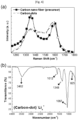
- FIG. 4 (a) is a Raman spectrum of carbon fiber and carbon quantum dots which are raw materials of the carbon quantum dot ionic compound electrolyte prepared according to the present invention
- (b) is the FT-IR spectrum of the Li-carbon quantum dot ionic compound.
- the disordered graphitic lattice D1 (approximately 1350 cm -1 ) band which was strong in carbon fiber, was reduced in the carbon quantum dot ionic compound and instead the intensity of the amorphous carbon band D3 (approximately 1500 cm -1 ) was increased.
- the disordered graphitic lattice D1 approximately 1350 cm -1
- D3 approximately 1500 cm -1
- FIG. 5 is an X-ray photoelectron spectroscopy (XPS) result of a lithium ion compound among carbon quantum dot ionic compounds prepared in Example 1 of the present invention.
- XPS X-ray photoelectron spectroscopy
- FIG. 6 is a thermal analysis of the carbon quantum dot ionic compound powder obtained in the embodiment of the present invention. As shown in FIG. 6 , seeing that decomposition starts at a temperature of about 600 °C or more, the thermal stability of the carbon quantum dot ionic compound electrolyte according to the invention is very excellent.
- Example 1 a carbon quantum dot ionic compound prepared with a carbon quantum dot having a size of 5.5 nm was used.
- Carbon quantum dot anion-potassium cationic electrolyte was applied to electrochromic device, carbon quantum dot anion-sodium cation was applied to electrochemical light emitting device, and carbon quantum dot anion-lithium cation was applied to lithium secondary battery system.
- a color change material layer is formed on a conductive transparent substrate as the first electrode by immersing the substrate in an aqueous solution containing 0.05 M HCl, 0.05 M K 3 Fe(CN) 6 , and 0.05 M FeCl 3 ⁇ 6 H 2 O.
- the thickness of the color change material layer can be regulated by controlling the current and time using chronopotentiometry.
- the color change material was formed on the first electrode (working electrode) with 40 uA and 140 s.
- ZnO buffer layer was formed by immersing another conductive transparent substrate in 5 mM ZnCl 2 , 0.1 M KCl, and an oxygen-saturated aqueous solution for 1000 s while applying -1 V at room temperature.
- the ZnO buffer layered transparent electrode was immersed in 0.5 mM ZnCl 2 , 0.1 M KCI, and saturated oxygen solution at 80 °C for 1000 s while applying -1 V, and then ZnO NW(nanowire)s layer was formed thereon, which was used as a second electrode (relative electrode).
- the first electrode (working electrode) and the second electrode (relative electrode) were attached on the inside of the electrochromic devices in the form of a sandwich using a thermal tape with the distance of 60um between the two electrodes.
- 0.5M solutions of carbon quantum dot ionic compound of with respective Li, Na, and K were injected into the corresponding electrochromic device.
- the pH of the aqueous electrolyte solutions were adjusted to 4, respectively.
- An electrochromic device was manufactured in the same manner as in Example 1, except that 0.5 M potassium chloride (KCI) was used as the electrolyte.
- KCI potassium chloride
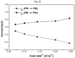
- FIG. 8 shows the results of performing cyclic voltammetry (CV) at a scan rate of 0.02 V / s using the three-electrode including a first electrode, a platinum (Pt) second electrode, and a reference electrode (Ag / AgCl) including a color change material in an aqueous solution containing a carbon quantum dot ionic compound according to the present invention.
- CV cyclic voltammetry
- Oxidative current is a coloration reaction (PB) and the reductive current is a decoloration reaction (PW).
- PB coloration reaction
- PW decoloration reaction
- FIG. 10 is an electrochemical impedance spectroscopy of the electrochemical devices of Example 2 and Comparative Example 1 measured by changing metal cations in carbon quantum dot ionic compounds using three electrode system, and Table 2 summarizes the measured impedance measurements with coloration reaction (PB) and the reductive current is a decoloration reaction (PW) using the circulating current voltage method in the three-electrode system.
- PB coloration reaction
- PW decoloration reaction
- FIG. 11 shows the test result of electrolyte durability of an electrochromic device, which is an example of electrochemical devices manufactured in Examples and Comparative Examples according to the present invention.
- color change efficiency maintained constant even after 1000 cycles in the electrochromic device using a electrolyte, (C-dot) - K + , according to the present invention, whereas the color change efficiency is reduced to less than the initial half level within 50 cycles in the electrochromic device using a conventional KCI electrolyte. This means that the electrochromic device using the (C-dot) - K + electrolyte has excellent durability.
- the discoloration efficiency values of 0.5 M KCI and (C-dot) - K + electrolyte were 81.6 cm 2 /C and 103.0 cm 2 /C, respectively. Therefore, it can be concluded that electrochromic devices using a carbon quantum dot ionic compounds are relatively superior in electrochromic stability and discoloration efficiency than that using KCI electrolyte.
- An electrochemical light emitting device was prepared ad follows;
- FIG. 12 shows a light emission intensity measurement result according to the carbon quantum dot ion compound concentration under the two-electrode system conditions for the electroluminescent device in one embodiment according to the present invention.
- the carbon quantum point anion-metal cation ion compound concentration is increased, the ionic conductivity is improved, thereby reducing the resistance in the device and eventually increasing the luminescence intensity.
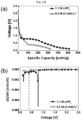
- FIG. 13 shows the results of measuring the specific capacitance with charging and discharging the lithium secondary battery applying the carbon quantum anion-lithium metal cation ion compound electrolyte of the present invention instead of LiPF6 electrolyte of the conventional secondary battery.
- the anode of the battery was constructed using Li 4 Ti 5 O 12 (active material, LTO), 10 wt.% PVDF (binder) and NMP (Solvent), and the cathode was graphite.
- the concentration of the carbon quantum point anion-lithium metal cation ion compound electrolyte was 0.5M. As shown in FIG, 13 , it was found that a stable charge / discharge cycle is observed in the secondary battery.
- FIG. 15 (a) is the result of the 0.5M concentration electrolyte
- (b) is the result of measuring the cycle for each concentration.
- the rate characteristic of the relatively high concentration of 0.5M sample was the best.
- that of 0.5M sample is the best at all current density. The results were summarized in Table 5.
- FIG. 16 shows voltage-capacitance measurement results measured at an electrode of both lithium ion batteries applying a carbon quantum dot ion compound electrolyte and a LiPF 6 electrolyte respectively in Example 5 of the present invention and (b) is differential result with respect to voltage. As shown in FIG.
- Equation 1 is a formula for obtaining the ion mobility index of the cation. The equation is represented by a number from 0 to 1, and the closer to 1, the higher the contribution of charge transfer by cation.
- t C I C I C + I A
- Equation 1 may be expressed as Equation 2 below to measure the ion mobility index of Li ions.
- t Li I SS V ⁇ I O R O I O V ⁇ I SS R SS
- t Li Lithium transference number
- V Applied potential
- R O Initial resistance of the passivation layer
- R SS Resistance of the passivation layer
- I O Initial current
- Iss Steady state current.
- a symmetrical cell of Li metal / electrolyte / Li metal was prepared, initial impedance R O was measured(frequency range: 100 kHz-0.1 Hz), DC polarization experiment was performed at 0.05 mV to measure I SS , I O , and the impedance was measured again to determine R SS . And the result of that using LiPF 6 as the electrolyte in the same manner was measured as a comparative example.
- FIG. 17 and Table 6 summarize the results.
- the carbon quantum dot anion-lithium cation ionic compound electrolyte of the present invention was found to be 1.5 to 2 times higher charge transfer index by the cation than LiPF 6 .
- the high t Li of the electrolyte of the present invention is deemed to be caused by the large anion radius of the carbon dot.
Landscapes
- Chemical & Material Sciences (AREA)
- Engineering & Computer Science (AREA)
- Chemical Kinetics & Catalysis (AREA)
- General Chemical & Material Sciences (AREA)
- Electrochemistry (AREA)
- Manufacturing & Machinery (AREA)
- Physics & Mathematics (AREA)
- Inorganic Chemistry (AREA)
- General Physics & Mathematics (AREA)
- Condensed Matter Physics & Semiconductors (AREA)
- Materials Engineering (AREA)
- Spectroscopy & Molecular Physics (AREA)
- Dispersion Chemistry (AREA)
- Secondary Cells (AREA)
- Electrochromic Elements, Electrophoresis, Or Variable Reflection Or Absorption Elements (AREA)
- Carbon And Carbon Compounds (AREA)
- Conductive Materials (AREA)
Claims (9)
- Elektrolyt (100) für eine elektrochemische Vorrichtung (14) mit einer ersten Elektrode (10), einer von der ersten Elektrode (10) beabstandet angeordneten zweiten Elektrode (11) und einem zwischen der ersten Elektrode (10) und der zweiten Elektrode (11) eingefüllten Elektrolyten (100), dadurch gekennzeichnet, dass der Elektrolyt (100) eine Salzform von einem Kohlenstoff-Quantenpunkt-Anion (12) mit einem durchschnittlichen Durchmesser im Bereich von 2 bis 12 Nanometern (nm) und einem Oberflächenpotential von -20 vM oder weniger und einem Metallkation (13) enthält, wobei die Größe des Kohlenstoff-Quantenpunkts (12) mit einem Elektronenmikroskop gemessen wird.
- Elektrolyt (100) nach Anspruch 1, dadurch gekennzeichnet, dass das Metall (15) ein Alkalimetall, Erdalkalimetall oder Übergangsmetall ist.
- Elektrolyt (100) nach Anspruch 2, dadurch gekennzeichnet, dass das Metall (15) zumindest eines, ausgewählt aus der Gruppe bestehend aus Li, Na, K, Mg und Zn, ist.
- Elektrolyt (100) nach Anspruch 1, dadurch gekennzeichnet, dass eine reversible elektrochemische Redoxreaktion in zumindest einer aus erster Elektrode (10) und zweiter Elektrode (11) erfolgt.
- Elektrolyt (100) nach einem der Ansprüche 1 bis 4, dadurch gekennzeichnet, dass die elektrochemische Vorrichtung (14) ausgewählt ist aus der Gruppe bestehend aus einer Sekundärbatterie, einer Solarzelle, einer elektrochromen Vorrichtung und einer elektrolumineszenten Vorrichtung.
- Elektrolyt (100) nach Anspruch 5, dadurch gekennzeichnet, dass die Sekundärbatterie eine Lithium-Ionen-Batterie oder eine Lithium-Polymer-Batterie ist.
- Verfahren zur Herstellung eines Elektrolyten (100) für eine elektrochemische Vorrichtung (14), umfassend die folgenden Schritte:i) Mischen des Kohlenstoffvorläufers und der Säure und hydrothermale Synthese im Bereich von 80 bis 120 °C, um einen Kohlenstoff-Quantenpunkt (12) mit einem durchschnittlichen Durchmesser im Bereich von 2 bis 12 Nanometern (nm) und dem Oberflächenpotential von -20 mV oder weniger herzustellen;ii) Herstellen eines Kohlenstoff-Quanten-Anion-Metallkation-Salzes durch Umsetzen des Kohlenstoff-Quantenpunktes (12) mit einem Metallion (13);iii) Entfernen von Reaktionsverunreinigungen; undiv) Klassifizieren der Kohlenstoff-Quantenpunkt-Ionen-Verbindungen nach ihrer Größe.
- Verfahren nach Anspruch 7, dadurch gekennzeichnet, dass das Metall (15) ein Alkalimetall, Erdalkalimetall oder Übergangsmetall ist.
- Verfahren nach Anspruch 8, dadurch gekennzeichnet, dass das Metall (15) zumindest eines, ausgewählt aus der Gruppe bestehend aus Li, Na, K, Mg und Zn, ist.
Applications Claiming Priority (3)
| Application Number | Priority Date | Filing Date | Title |
|---|---|---|---|
| KR20170064227 | 2017-05-24 | ||
| KR1020180058231A KR102016642B1 (ko) | 2017-05-24 | 2018-05-23 | 전기화학소자용 전해질 및 그 제조방법 |
| PCT/KR2018/005922 WO2018217043A1 (ko) | 2017-05-24 | 2018-05-24 | 전기화학소자용 전해질 및 그 제조방법 |
Publications (4)
| Publication Number | Publication Date |
|---|---|
| EP3633687A1 EP3633687A1 (de) | 2020-04-08 |
| EP3633687A4 EP3633687A4 (de) | 2021-03-10 |
| EP3633687B1 true EP3633687B1 (de) | 2025-01-01 |
| EP3633687C0 EP3633687C0 (de) | 2025-01-01 |
Family
ID=64669031
Family Applications (1)
| Application Number | Title | Priority Date | Filing Date |
|---|---|---|---|
| EP18805568.5A Active EP3633687B1 (de) | 2017-05-24 | 2018-05-24 | Elektrolyt für elektrochemische vorrichtung und herstellungsverfahren dafür |
Country Status (5)
| Country | Link |
|---|---|
| US (1) | US20200091557A1 (de) |
| EP (1) | EP3633687B1 (de) |
| JP (1) | JP6964767B2 (de) |
| KR (1) | KR102016642B1 (de) |
| CN (1) | CN110663086B (de) |
Families Citing this family (10)
| Publication number | Priority date | Publication date | Assignee | Title |
|---|---|---|---|---|
| CN109742444A (zh) | 2019-01-10 | 2019-05-10 | 天津大学 | 聚合物固态电解质、其制备方法与锂化碳点的制备方法 |
| KR102221190B1 (ko) * | 2019-02-26 | 2021-03-03 | 한국과학기술연구원 | 금속입자를 포함하는 질소 도핑 탄소 양자점 및 이의 제조방법 |
| CN111540946A (zh) * | 2020-04-13 | 2020-08-14 | 江苏大学 | 一种掺杂碳量子点的有机聚合物固态电解质及其制备方法 |
| CN112909333B (zh) * | 2021-01-19 | 2022-08-23 | 中北大学 | 一种含硼碳量子点纳米复合固态电解质及其制备方法 |
| CN113998692A (zh) * | 2021-10-12 | 2022-02-01 | 中南大学 | 石墨烯量子点及其制备方法、含有其的电解液及该电解液在锌离子电池中的应用 |
| WO2023070473A1 (zh) * | 2021-10-28 | 2023-05-04 | 京东方科技集团股份有限公司 | 量子点发光器件及其制备方法、显示基板和显示装置 |
| CN114974925B (zh) * | 2022-06-23 | 2024-07-09 | 广东风华高新科技股份有限公司 | 一种电解液添加剂及其制备方法和应用 |
| CN117619452A (zh) * | 2022-08-12 | 2024-03-01 | 中国石油化工股份有限公司 | 一种改性硅铝催化材料及其制备方法和应用 |
| KR102948745B1 (ko) * | 2022-09-14 | 2026-04-09 | 주식회사 그래피니드테크놀로지 | 전해질 첨가제, 이를 포함하는 리튬 금속 전지용 전해질 |
| WO2025041614A1 (ja) * | 2023-08-21 | 2025-02-27 | ナミックス株式会社 | ハイブリッド量子ドットの製造方法、ハイブリッド量子ドット、エネルギー貯蔵デバイス、エネルギー発生デバイス、及びバリスタ形成用ペースト |
Family Cites Families (27)
| Publication number | Priority date | Publication date | Assignee | Title |
|---|---|---|---|---|
| US5569560A (en) | 1995-04-12 | 1996-10-29 | Olsen; Ib I. | Complexing agent for improved performance in a lithium based hybrid electrolyte |
| US7923801B2 (en) * | 2007-04-18 | 2011-04-12 | Invisage Technologies, Inc. | Materials, systems and methods for optoelectronic devices |
| KR100934732B1 (ko) * | 2007-06-01 | 2009-12-30 | 한국기계연구원 | 양자점을 이용한 태양전지 및 이의 제조방법 |
| WO2009130316A1 (en) | 2008-04-24 | 2009-10-29 | Chromogenics Ab | Electrolytes for electrochromic devices |
| CN102356129B (zh) | 2009-01-15 | 2014-03-12 | 康奈尔大学 | 纳米颗粒有机杂交材料(nohm) |
| CA2803772C (en) * | 2010-06-25 | 2017-03-28 | National University Of Singapore | Methods of forming graphene by graphite exfoliation |
| US8900755B2 (en) * | 2010-09-23 | 2014-12-02 | Nanotek Instruments, Inc. | Lithium super-battery with a chemically functionalized disordered carbon cathode |
| US20120171093A1 (en) * | 2010-11-03 | 2012-07-05 | Massachusetts Institute Of Technology | Compositions comprising functionalized carbon-based nanostructures and related methods |
| US9779883B2 (en) * | 2011-09-07 | 2017-10-03 | Nanotek Instruments, Inc. | Partially surface-mediated lithium ion-exchanging cells and method for operating same |
| CN102522219A (zh) * | 2011-12-15 | 2012-06-27 | 东南大学 | 一种量子点敏化太阳能电池及其制备方法 |
| EP2688133B1 (de) | 2012-07-19 | 2015-03-25 | CIC Energigune | Hybridelektrolyt |
| US10651409B2 (en) * | 2012-07-20 | 2020-05-12 | Nutech Ventures | Narrowband nanocomposite photodetector |
| KR20160003231A (ko) * | 2013-05-02 | 2016-01-08 | 윌리엄 마쉬 라이스 유니버시티 | 석탄 및 코크스로부터의 그래핀 양자점의 제조 방법 |
| JP6211687B2 (ja) * | 2013-05-24 | 2017-10-11 | カウンシル オブ サイエンティフィック アンド インダストリアル リサーチ | ナノ多孔性グラフェンとグラフェン量子ドットを作製する方法 |
| KR20150004124A (ko) | 2013-07-02 | 2015-01-12 | 이남석 | 곡물 로스팅 장치 |
| JP6190660B2 (ja) * | 2013-08-12 | 2017-08-30 | 株式会社Kri | グラフェン量子ドット発光体の製造方法 |
| KR101790275B1 (ko) * | 2013-10-24 | 2017-10-26 | 한국과학기술원 | 고품질 그래핀 양자점 및 이의 제조방법 |
| KR101534313B1 (ko) * | 2014-08-04 | 2015-07-06 | 성균관대학교산학협력단 | 탄소계 물질 및 비올로겐계 화합물을 포함하는 전기변색소자, 및 이의 제조 방법 |
| WO2016058466A1 (zh) * | 2014-10-13 | 2016-04-21 | 徐海波 | 电化学氧化切割碳系三维材料端面制的氧化石墨烯及方法 |
| CN107108461B (zh) * | 2014-11-06 | 2020-04-28 | 浦项工科大学校产学协力团 | 钙钛矿纳米结晶粒子及利用该粒子的光电元件 |
| CN104941643A (zh) * | 2015-06-16 | 2015-09-30 | 北京科技大学 | 一种银-石墨烯量子点/氧化锌三元光催化剂的制备方法 |
| TWI577039B (zh) * | 2016-04-15 | 2017-04-01 | 張家耀 | 量子點敏化太陽能電池及利用共吸附劑提升量子點敏化太陽能電池之光電性能的方法 |
| CN106206032A (zh) * | 2016-06-24 | 2016-12-07 | 中国海洋大学 | 一种用天然大分子制备的石墨烯量子点及其在制备量子点敏化太阳能电池中的应用 |
| KR102586044B1 (ko) * | 2016-08-10 | 2023-10-10 | 삼성디스플레이 주식회사 | 발광 소자 |
| CN106129469B (zh) * | 2016-09-08 | 2019-01-29 | 中南大学 | 一种复合固态聚合物电解质及制备方法 |
| WO2017077381A2 (en) * | 2016-11-17 | 2017-05-11 | Research Institute Of Petroleum Industry (Ripi) | Formulation for the synthesis of thermal nanofluid based on carbon nanodots |
| CN106504906B (zh) * | 2016-12-01 | 2018-09-21 | 中国石油大学(华东) | 碳量子点/氢氧化镍电化学储能材料、合成方法及应用 |
-
2018
- 2018-05-23 KR KR1020180058231A patent/KR102016642B1/ko active Active
- 2018-05-24 EP EP18805568.5A patent/EP3633687B1/de active Active
- 2018-05-24 CN CN201880034578.5A patent/CN110663086B/zh active Active
- 2018-05-24 JP JP2020516360A patent/JP6964767B2/ja active Active
- 2018-05-24 US US16/616,283 patent/US20200091557A1/en active Pending
Also Published As
| Publication number | Publication date |
|---|---|
| KR102016642B1 (ko) | 2019-08-30 |
| EP3633687A1 (de) | 2020-04-08 |
| CN110663086B (zh) | 2021-11-12 |
| US20200091557A1 (en) | 2020-03-19 |
| CN110663086A (zh) | 2020-01-07 |
| JP6964767B2 (ja) | 2021-11-10 |
| EP3633687A4 (de) | 2021-03-10 |
| JP2020522115A (ja) | 2020-07-27 |
| EP3633687C0 (de) | 2025-01-01 |
| KR20180128855A (ko) | 2018-12-04 |
Similar Documents
| Publication | Publication Date | Title |
|---|---|---|
| EP3633687B1 (de) | Elektrolyt für elektrochemische vorrichtung und herstellungsverfahren dafür | |
| EP3633445B1 (de) | Elektrochemische vorrichtung mit einem ionischen kohlenstoffquantenpunkt-verbundelektrolyt | |
| Zhu et al. | Bifunctional 2D-on-2D MoO 3 nanobelt/Ni (OH) 2 nanosheets for supercapacitor-driven electrochromic energy storage | |
| Zhou et al. | All-solid-state electrochromic devices based on WO3|| NiO films: material developments and future applications | |
| Wei et al. | Improved stability of electrochromic devices using Ti-doped V2O5 film | |
| KR100663032B1 (ko) | 공융혼합물을 포함하는 전해질 및 이를 이용한 전기 변색소자 | |
| Etman et al. | Molybdenum oxide nanosheets with tunable plasmonic resonance: aqueous exfoliation synthesis and charge storage applications | |
| Bella | Polymer electrolytes and perovskites: lights and shadows in photovoltaic devices | |
| CN102780033B (zh) | 含低共熔混合物的电解质、电化学装置和电致变色装置 | |
| Ma et al. | Controllable growth of high-quality metal oxide/conducting polymer hierarchical nanoarrays with outstanding electrochromic properties and solar-heat shielding ability | |
| Tong et al. | Versatile displays based on a 3-dimensionally ordered macroporous vanadium oxide film for advanced electrochromic devices | |
| Han et al. | Black-to-transparent electrochromic capacitive windows based on conjugated polymers | |
| Reddy et al. | Dual purpose poly (3, 4-ethylenedioxypyrrole)/vanadium pentoxide nanobelt hybrids in photoelectrochromic cells and supercapacitors | |
| WO2018217044A1 (ko) | 탄소양자점 이온화합물 전해질을 포함한 전기화학소자 | |
| Ozdemir et al. | Electropolymerization of pyrrole from a deep eutectic solvent for supercapacitor applications | |
| Wu et al. | Electrochromic materials: scope for the cyclic decay mechanisms and performance stability optimisation strategies | |
| US12325636B2 (en) | Reduced graphene oxide | |
| WO2018217043A1 (ko) | 전기화학소자용 전해질 및 그 제조방법 | |
| Morankar et al. | Catalytic synergy in palladium-enriched tungsten oxide nanogranules: redefining electrochromic dynamics and energy storage capabilities | |
| JP5317322B2 (ja) | 電気化学キャパシタ及びその製造方法。 | |
| Thongpan et al. | Surface modification of NiO films through magnetic field-assisted sparking process for enhancing electrochromic durability and efficiency | |
| Coffey et al. | Valence Technology, Inc., 301 Conestoga Way, Henderson, NV 89015, USA | |
| Córdoba de Torresi et al. | Layer‐by‐Layer Assembly of Electrochromic Materials: On the Efficient Method for Immobilisation of Nanomaterials | |
| Kang et al. | Ultra‑Stable Wo3 Electrochromic Film Based on Nh4+ Hydrogen Bond Chemistry | |
| Zhang et al. | Study on Core-Shell Structured Polyaniline Films Based on PSS/MnO2 Synergistic Doping and Their Performance |
Legal Events
| Date | Code | Title | Description |
|---|---|---|---|
| STAA | Information on the status of an ep patent application or granted ep patent |
Free format text: STATUS: THE INTERNATIONAL PUBLICATION HAS BEEN MADE |
|
| PUAI | Public reference made under article 153(3) epc to a published international application that has entered the european phase |
Free format text: ORIGINAL CODE: 0009012 |
|
| STAA | Information on the status of an ep patent application or granted ep patent |
Free format text: STATUS: REQUEST FOR EXAMINATION WAS MADE |
|
| 17P | Request for examination filed |
Effective date: 20191218 |
|
| AK | Designated contracting states |
Kind code of ref document: A1 Designated state(s): AL AT BE BG CH CY CZ DE DK EE ES FI FR GB GR HR HU IE IS IT LI LT LU LV MC MK MT NL NO PL PT RO RS SE SI SK SM TR |
|
| AX | Request for extension of the european patent |
Extension state: BA ME |
|
| DAV | Request for validation of the european patent (deleted) | ||
| DAX | Request for extension of the european patent (deleted) | ||
| RIN1 | Information on inventor provided before grant (corrected) |
Inventor name: LIM, HONG CHUL Inventor name: SHIN, IK SOO |
|
| A4 | Supplementary search report drawn up and despatched |
Effective date: 20210204 |
|
| RIC1 | Information provided on ipc code assigned before grant |
Ipc: H01L 51/50 20060101ALN20210129BHEP Ipc: H01M 10/0525 20100101ALI20210129BHEP Ipc: H01M 10/0565 20100101AFI20210129BHEP Ipc: H01M 10/0568 20100101ALI20210129BHEP Ipc: G02F 1/1523 20190101ALN20210129BHEP |
|
| REG | Reference to a national code |
Ref legal event code: R079 Free format text: PREVIOUS MAIN CLASS: H01B0001120000 Ref country code: DE Ref document number: 602018078155 Country of ref document: DE Ipc: H01M0010056500 |
|
| GRAP | Despatch of communication of intention to grant a patent |
Free format text: ORIGINAL CODE: EPIDOSNIGR1 |
|
| STAA | Information on the status of an ep patent application or granted ep patent |
Free format text: STATUS: GRANT OF PATENT IS INTENDED |
|
| RIC1 | Information provided on ipc code assigned before grant |
Ipc: H10K 50/135 20230101ALN20240719BHEP Ipc: G02F 1/1523 20190101ALN20240719BHEP Ipc: H01M 10/0568 20100101ALI20240719BHEP Ipc: H01M 10/0525 20100101ALI20240719BHEP Ipc: H01M 10/0565 20100101AFI20240719BHEP |
|
| INTG | Intention to grant announced |
Effective date: 20240805 |
|
| GRAS | Grant fee paid |
Free format text: ORIGINAL CODE: EPIDOSNIGR3 |
|
| GRAA | (expected) grant |
Free format text: ORIGINAL CODE: 0009210 |
|
| STAA | Information on the status of an ep patent application or granted ep patent |
Free format text: STATUS: THE PATENT HAS BEEN GRANTED |
|
| AK | Designated contracting states |
Kind code of ref document: B1 Designated state(s): AL AT BE BG CH CY CZ DE DK EE ES FI FR GB GR HR HU IE IS IT LI LT LU LV MC MK MT NL NO PL PT RO RS SE SI SK SM TR |
|
| REG | Reference to a national code |
Ref country code: GB Ref legal event code: FG4D |
|
| REG | Reference to a national code |
Ref country code: DE Ref legal event code: R096 Ref document number: 602018078155 Country of ref document: DE |
|
| REG | Reference to a national code |
Ref country code: CH Ref legal event code: EP |
|
| REG | Reference to a national code |
Ref country code: IE Ref legal event code: FG4D |
|
| U01 | Request for unitary effect filed |
Effective date: 20250101 |
|
| U07 | Unitary effect registered |
Designated state(s): AT BE BG DE DK EE FI FR IT LT LU LV MT NL PT RO SE SI Effective date: 20250110 |
|
| U20 | Renewal fee for the european patent with unitary effect paid |
Year of fee payment: 8 Effective date: 20250528 |
|
| PG25 | Lapsed in a contracting state [announced via postgrant information from national office to epo] |
Ref country code: PL Free format text: LAPSE BECAUSE OF FAILURE TO SUBMIT A TRANSLATION OF THE DESCRIPTION OR TO PAY THE FEE WITHIN THE PRESCRIBED TIME-LIMIT Effective date: 20250101 |
|
| PG25 | Lapsed in a contracting state [announced via postgrant information from national office to epo] |
Ref country code: ES Free format text: LAPSE BECAUSE OF FAILURE TO SUBMIT A TRANSLATION OF THE DESCRIPTION OR TO PAY THE FEE WITHIN THE PRESCRIBED TIME-LIMIT Effective date: 20250101 |
|
| PG25 | Lapsed in a contracting state [announced via postgrant information from national office to epo] |
Ref country code: NO Free format text: LAPSE BECAUSE OF FAILURE TO SUBMIT A TRANSLATION OF THE DESCRIPTION OR TO PAY THE FEE WITHIN THE PRESCRIBED TIME-LIMIT Effective date: 20250401 Ref country code: IS Free format text: LAPSE BECAUSE OF FAILURE TO SUBMIT A TRANSLATION OF THE DESCRIPTION OR TO PAY THE FEE WITHIN THE PRESCRIBED TIME-LIMIT Effective date: 20250501 |
|
| PG25 | Lapsed in a contracting state [announced via postgrant information from national office to epo] |
Ref country code: HR Free format text: LAPSE BECAUSE OF FAILURE TO SUBMIT A TRANSLATION OF THE DESCRIPTION OR TO PAY THE FEE WITHIN THE PRESCRIBED TIME-LIMIT Effective date: 20250101 |
|
| PG25 | Lapsed in a contracting state [announced via postgrant information from national office to epo] |
Ref country code: GR Free format text: LAPSE BECAUSE OF FAILURE TO SUBMIT A TRANSLATION OF THE DESCRIPTION OR TO PAY THE FEE WITHIN THE PRESCRIBED TIME-LIMIT Effective date: 20250402 |
|
| PG25 | Lapsed in a contracting state [announced via postgrant information from national office to epo] |
Ref country code: CZ Free format text: LAPSE BECAUSE OF FAILURE TO SUBMIT A TRANSLATION OF THE DESCRIPTION OR TO PAY THE FEE WITHIN THE PRESCRIBED TIME-LIMIT Effective date: 20250101 |
|
| PG25 | Lapsed in a contracting state [announced via postgrant information from national office to epo] |
Ref country code: SM Free format text: LAPSE BECAUSE OF FAILURE TO SUBMIT A TRANSLATION OF THE DESCRIPTION OR TO PAY THE FEE WITHIN THE PRESCRIBED TIME-LIMIT Effective date: 20250101 |
|
| PG25 | Lapsed in a contracting state [announced via postgrant information from national office to epo] |
Ref country code: SK Free format text: LAPSE BECAUSE OF FAILURE TO SUBMIT A TRANSLATION OF THE DESCRIPTION OR TO PAY THE FEE WITHIN THE PRESCRIBED TIME-LIMIT Effective date: 20250101 |
|
| PLBE | No opposition filed within time limit |
Free format text: ORIGINAL CODE: 0009261 |
|
| STAA | Information on the status of an ep patent application or granted ep patent |
Free format text: STATUS: NO OPPOSITION FILED WITHIN TIME LIMIT |
|
| REG | Reference to a national code |
Ref country code: CH Ref legal event code: L10 Free format text: ST27 STATUS EVENT CODE: U-0-0-L10-L00 (AS PROVIDED BY THE NATIONAL OFFICE) Effective date: 20251112 |
|
| 26N | No opposition filed |
Effective date: 20251002 |
|
| REG | Reference to a national code |
Ref country code: CH Ref legal event code: H13 Free format text: ST27 STATUS EVENT CODE: U-0-0-H10-H13 (AS PROVIDED BY THE NATIONAL OFFICE) Effective date: 20251223 |
|
| PG25 | Lapsed in a contracting state [announced via postgrant information from national office to epo] |
Ref country code: CH Free format text: LAPSE BECAUSE OF NON-PAYMENT OF DUE FEES Effective date: 20250531 |
|
| GBPC | Gb: european patent ceased through non-payment of renewal fee |
Effective date: 20250524 |
|
| PG25 | Lapsed in a contracting state [announced via postgrant information from national office to epo] |
Ref country code: MC Free format text: LAPSE BECAUSE OF FAILURE TO SUBMIT A TRANSLATION OF THE DESCRIPTION OR TO PAY THE FEE WITHIN THE PRESCRIBED TIME-LIMIT Effective date: 20250101 |
|
| PG25 | Lapsed in a contracting state [announced via postgrant information from national office to epo] |
Ref country code: GB Free format text: LAPSE BECAUSE OF NON-PAYMENT OF DUE FEES Effective date: 20250524 |
|
| PG25 | Lapsed in a contracting state [announced via postgrant information from national office to epo] |
Ref country code: IE Free format text: LAPSE BECAUSE OF NON-PAYMENT OF DUE FEES Effective date: 20250524 |