EP3633698A1 - Magnetherstellungsverfahren und magnetmagnetisierungsverfahren - Google Patents
Magnetherstellungsverfahren und magnetmagnetisierungsverfahren Download PDFInfo
- Publication number
- EP3633698A1 EP3633698A1 EP18805587.5A EP18805587A EP3633698A1 EP 3633698 A1 EP3633698 A1 EP 3633698A1 EP 18805587 A EP18805587 A EP 18805587A EP 3633698 A1 EP3633698 A1 EP 3633698A1
- Authority
- EP
- European Patent Office
- Prior art keywords
- magnet
- magnetization
- unmagnetized
- assembly
- degrees
- Prior art date
- Legal status (The legal status is an assumption and is not a legal conclusion. Google has not performed a legal analysis and makes no representation as to the accuracy of the status listed.)
- Withdrawn
Links
- 238000000034 method Methods 0.000 title claims abstract description 59
- 238000004519 manufacturing process Methods 0.000 title claims abstract description 51
- 230000005415 magnetization Effects 0.000 claims abstract description 192
- 239000000463 material Substances 0.000 claims abstract description 143
- 230000004907 flux Effects 0.000 claims description 35
- 230000004308 accommodation Effects 0.000 description 24
- 238000005259 measurement Methods 0.000 description 14
- 230000008569 process Effects 0.000 description 11
- 239000003990 capacitor Substances 0.000 description 7
- 238000007796 conventional method Methods 0.000 description 7
- 239000006249 magnetic particle Substances 0.000 description 4
- 239000000853 adhesive Substances 0.000 description 3
- 230000001070 adhesive effect Effects 0.000 description 3
- 238000004458 analytical method Methods 0.000 description 3
- BGPVFRJUHWVFKM-UHFFFAOYSA-N N1=C2C=CC=CC2=[N+]([O-])C1(CC1)CCC21N=C1C=CC=CC1=[N+]2[O-] Chemical compound N1=C2C=CC=CC2=[N+]([O-])C1(CC1)CCC21N=C1C=CC=CC1=[N+]2[O-] BGPVFRJUHWVFKM-UHFFFAOYSA-N 0.000 description 2
- 230000009471 action Effects 0.000 description 2
- 238000001887 electron backscatter diffraction Methods 0.000 description 2
- 239000000696 magnetic material Substances 0.000 description 2
- 229910001172 neodymium magnet Inorganic materials 0.000 description 2
- 229910052761 rare earth metal Inorganic materials 0.000 description 2
- 150000002910 rare earth metals Chemical class 0.000 description 2
- 229920005989 resin Polymers 0.000 description 2
- 239000011347 resin Substances 0.000 description 2
- QJVKUMXDEUEQLH-UHFFFAOYSA-N [B].[Fe].[Nd] Chemical compound [B].[Fe].[Nd] QJVKUMXDEUEQLH-UHFFFAOYSA-N 0.000 description 1
- 229910045601 alloy Inorganic materials 0.000 description 1
- 239000000956 alloy Substances 0.000 description 1
- 230000000712 assembly Effects 0.000 description 1
- 238000000429 assembly Methods 0.000 description 1
- 230000008859 change Effects 0.000 description 1
- 230000007423 decrease Effects 0.000 description 1
- 230000005347 demagnetization Effects 0.000 description 1
- 230000006866 deterioration Effects 0.000 description 1
- 238000007599 discharging Methods 0.000 description 1
- 230000000694 effects Effects 0.000 description 1
- 239000003822 epoxy resin Substances 0.000 description 1
- 238000011156 evaluation Methods 0.000 description 1
- 230000020169 heat generation Effects 0.000 description 1
- 230000035699 permeability Effects 0.000 description 1
- 238000005498 polishing Methods 0.000 description 1
- 229920000647 polyepoxide Polymers 0.000 description 1
Images





Classifications
-
- B—PERFORMING OPERATIONS; TRANSPORTING
- B22—CASTING; POWDER METALLURGY
- B22F—WORKING METALLIC POWDER; MANUFACTURE OF ARTICLES FROM METALLIC POWDER; MAKING METALLIC POWDER; APPARATUS OR DEVICES SPECIALLY ADAPTED FOR METALLIC POWDER
- B22F3/00—Manufacture of workpieces or articles from metallic powder characterised by the manner of compacting or sintering; Apparatus specially adapted therefor ; Presses and furnaces
- B22F3/24—After-treatment of workpieces or articles
-
- H—ELECTRICITY
- H01—ELECTRIC ELEMENTS
- H01F—MAGNETS; INDUCTANCES; TRANSFORMERS; SELECTION OF MATERIALS FOR THEIR MAGNETIC PROPERTIES
- H01F13/00—Apparatus or processes for magnetising or demagnetising
- H01F13/003—Methods and devices for magnetising permanent magnets
-
- H—ELECTRICITY
- H01—ELECTRIC ELEMENTS
- H01F—MAGNETS; INDUCTANCES; TRANSFORMERS; SELECTION OF MATERIALS FOR THEIR MAGNETIC PROPERTIES
- H01F41/00—Apparatus or processes specially adapted for manufacturing or assembling magnets, inductances or transformers; Apparatus or processes specially adapted for manufacturing materials characterised by their magnetic properties
- H01F41/02—Apparatus or processes specially adapted for manufacturing or assembling magnets, inductances or transformers; Apparatus or processes specially adapted for manufacturing materials characterised by their magnetic properties for manufacturing cores, coils, or magnets
- H01F41/0253—Apparatus or processes specially adapted for manufacturing or assembling magnets, inductances or transformers; Apparatus or processes specially adapted for manufacturing materials characterised by their magnetic properties for manufacturing cores, coils, or magnets for manufacturing permanent magnets
-
- H—ELECTRICITY
- H01—ELECTRIC ELEMENTS
- H01F—MAGNETS; INDUCTANCES; TRANSFORMERS; SELECTION OF MATERIALS FOR THEIR MAGNETIC PROPERTIES
- H01F41/00—Apparatus or processes specially adapted for manufacturing or assembling magnets, inductances or transformers; Apparatus or processes specially adapted for manufacturing materials characterised by their magnetic properties
- H01F41/02—Apparatus or processes specially adapted for manufacturing or assembling magnets, inductances or transformers; Apparatus or processes specially adapted for manufacturing materials characterised by their magnetic properties for manufacturing cores, coils, or magnets
- H01F41/0253—Apparatus or processes specially adapted for manufacturing or assembling magnets, inductances or transformers; Apparatus or processes specially adapted for manufacturing materials characterised by their magnetic properties for manufacturing cores, coils, or magnets for manufacturing permanent magnets
- H01F41/0273—Imparting anisotropy
-
- H—ELECTRICITY
- H01—ELECTRIC ELEMENTS
- H01F—MAGNETS; INDUCTANCES; TRANSFORMERS; SELECTION OF MATERIALS FOR THEIR MAGNETIC PROPERTIES
- H01F7/00—Magnets
- H01F7/02—Permanent magnets [PM]
-
- H—ELECTRICITY
- H01—ELECTRIC ELEMENTS
- H01F—MAGNETS; INDUCTANCES; TRANSFORMERS; SELECTION OF MATERIALS FOR THEIR MAGNETIC PROPERTIES
- H01F7/00—Magnets
- H01F7/02—Permanent magnets [PM]
- H01F7/0205—Magnetic circuits with PM in general
-
- H—ELECTRICITY
- H02—GENERATION; CONVERSION OR DISTRIBUTION OF ELECTRIC POWER
- H02K—DYNAMO-ELECTRIC MACHINES
- H02K15/00—Processes or apparatus specially adapted for manufacturing, assembling, maintaining or repairing of dynamo-electric machines
- H02K15/02—Processes or apparatus specially adapted for manufacturing, assembling, maintaining or repairing of dynamo-electric machines of stator or rotor bodies
- H02K15/03—Processes or apparatus specially adapted for manufacturing, assembling, maintaining or repairing of dynamo-electric machines of stator or rotor bodies having permanent magnets
-
- B—PERFORMING OPERATIONS; TRANSPORTING
- B22—CASTING; POWDER METALLURGY
- B22F—WORKING METALLIC POWDER; MANUFACTURE OF ARTICLES FROM METALLIC POWDER; MAKING METALLIC POWDER; APPARATUS OR DEVICES SPECIALLY ADAPTED FOR METALLIC POWDER
- B22F2202/00—Treatment under specific physical conditions
- B22F2202/05—Use of magnetic field
Definitions
- the present invention relates to a method for manufacturing a magnet and a method for magnetizing a magnet.
- a generator In machine tools, vehicles, aircraft, wind power generators, and the like, a generator is used to convert mechanical kinetic energy transmitted from an engine and the like into electrical energy, and a motor that conversely converts electrical energy into mechanical kinetic energy and the like is used.
- Halbach magnets have been proposed with respect to permanent magnets used for such motors and the like in order to further improve the magnetic characteristics.
- a Halbach magnet is a magnet made by combining a plurality of permanent magnet blocks in an array called a Halbach array.
- the magnetic field strength in a specific direction can be improved by optimizing the directions of the magnetic poles of the permanent magnet blocks.
- Patent Document 1 Japanese Laid-Open Patent Publication No. 2016-029880
- Patent Document 1 it is reported that in such a method, for example, magnetization cannot be performed in a manner in which the magnetization directions differ by 90 degrees between adjacent unmagnetized magnet blocks (Patent Document 1). This is because, since the magnetic field usually has continuity, it is impossible in principle to apply a magnetic field along the orientation directions of the magnetization easy axes to adjacently arranged unmagnetized magnet blocks having different orientation directions of magnetization easy axes.
- the conventional method has a problem that it is difficult to manufacture a Halbach magnet with a high productivity.
- the present invention has been made in view of such a background, and it is an object of the present invention to provide a method for manufacturing a Halbach magnet with a higher productivity than the conventional method and a method for magnetizing an unmagnetized magnet with a higher productivity than a conventional method.
- the present invention provides a method for manufacturing a magnet, including:
- the present invention also provides a magnetizing method comprising:
- the present invention can provide a method for manufacturing a Halbach magnet with a higher productivity than the conventional method and a method for magnetizing an unmagnetized magnet with a higher productivity than a conventional method.
- FIG. 1 schematically illustrates a flow of a method for manufacturing a Halbach magnet (hereinafter referred to as "first manufacturing method") according to an embodiment of the present invention.
- the first manufacturing method includes:
- the "curved (pulse) magnetic field” in step S120 means a (pulse) magnetic field in which the directions of the magnetic field lines passing through the interior of the assembly (magnetization target body) are not straight lines but curved lines.
- An example of an unmagnetized magnet material in which the magnetization easy axis is oriented in a predetermined direction includes a parallel oriented unmagnetized magnet material in which the magnetization easy axes are aligned in a single direction.
- parallel oriented means, for example, an orientation in which a difference in the orientation directions of the magnetization easy axes at three points which equally divide into four a diagonal line on a face yielding the maximum surface magnetic flux density, when the unmagnetized magnet material is magnetized, is within 15 degrees.
- FIG. 2 is a perspective view schematically illustrating a form of an unmagnetized magnet material.
- this unmagnetized magnet material 110 has a substantially rectangular parallelepiped shape.
- a magnetization easy axis 140 of the magnetic particles is oriented in a predetermined direction.
- the magnetization easy axis 140 is oriented in the vertical direction (Z direction of FIG. 2 ).
- the orientation direction of the magnetization easy axis of the unmagnetized magnet material is determined based on a Halbach array of a Halbach magnet to be manufactured later.
- the magnetization easy axis 140 of the unmagnetized magnet material 110 may be oriented in a direction parallel to the Z axis in FIG. 2 , or may be at a predetermined angle (for example, 30 degrees, 45 degrees, or 90 degrees) with respect to the Z axis.
- the length of the shortest side of the unmagnetized magnet material 110 is, for example, in a range of 1 mm to 6 mm.
- the length of the shortest side is preferably in a range of 2 mm to 4 mm.
- the length of the longest side of the unmagnetized magnet material 110 is, for example, in a range of 5 mm to 50 mm.
- the unmagnetized magnet material 110 may be, for example, a rare earth sintered magnet in an unmagnetized state.
- the rare earth sintered magnet may be a neodymium-iron-boron alloy.
- Fig. 3 schematically illustrates a configuration example of the assembly.
- the assembly 160 has a substantially cuboid shape, and includes an upper face 162, a bottom face 164, and four side faces 166.
- the assembly 160 is made by arraying three materials, i.e., a first unmagnetized magnet material 110A, a second unmagnetized magnet material 110B, and a first unmagnetized magnet material 110A, into a row in this order.
- a first unmagnetized magnet material 110A a second unmagnetized magnet material 110B
- a first unmagnetized magnet material 110A a first unmagnetized magnet material 110A
- the direction in which the unmagnetized magnet materials are arrayed (direction X in FIG. 3 ) will also be referred to as an "array direction (of an unmagnetized magnet material)".
- an adhesive is actually interposed between the first unmagnetized magnet material 110A and the second unmagnetized magnet material 110B adjacent to each other.
- the first unmagnetized magnet material 110A and the second unmagnetized magnet material 110B are bonded to each other via this adhesive.
- the first unmagnetized magnet material 110A includes a first upper face 112A, a first bottom face 114A, and four first side faces 116A. It should be noted that, among six faces of the first unmagnetized magnet material 110A, a face that is bonded with the second unmagnetized magnet material 110B is especially referred to as a "first bonding target face".
- the second unmagnetized magnet material 110B includes a second upper face 112B, a second bottom face 114B, and four second side faces 116B. It should be noted that, among six faces of the second unmagnetized magnet material 110B, a face that is bonded with the first unmagnetized magnet material 110A is especially referred to as a "second bonding target face".
- the unmagnetized magnet materials 110A, 110B are arrayed in such a manner that the first bonding target face (one of the first side faces 116A) of the first unmagnetized magnet material 110A and the second bonding target face (one of the second side faces 116B) of the second unmagnetized magnet material 110B face each other, and the assembly 160 is made by repeating this process.
- the upper face 162 of the assembly 160 is formed by the first upper faces 112A of two first unmagnetized magnet materials 110A and the second upper face 112B of one second unmagnetized magnet material 110B.
- the bottom face 164 of the assembly 160 is formed by the first bottom faces 114A of two first unmagnetized magnet materials 110A and the second bottom face 114B of one second unmagnetized magnet material 110B.
- the distance between the upper face 162 and the bottom face 164 will be referred to as "thickness".
- the direction of the thickness of the assembly 160 is parallel to the Z direction.
- the thickness of the assembly 160 is in a range of 1 mm to 10 mm, more preferably in a range of 1 mm to 6 mm, and still more preferably in a range of 1.5 mm or more and less than 6 mm.
- the length along the array direction of the assembly 160 (hereinafter referred to as "array length") is preferably in a range of 10 mm to 40 mm.
- the size in the Z direction of the first unmagnetized magnet material 110A is configured to be equal to the size in the Z direction of the second unmagnetized magnet material 110B. Accordingly, the thickness of the assembly 160 can be uniform, and the polishing step for uniformizing the thickness of the Halbach magnet manufactured later can be omitted or simplified.
- the first unmagnetized magnet materials 110A are arranged in the assembly 160 such that magnetization easy axes 140A are parallel to the thickness direction of the assembly 160.
- the second unmagnetized magnet material 110B is arranged in the assembly 160 such that the magnetization easy axis 140B is parallel to the array direction of the unmagnetized magnet materials 110A and 110B.
- the angle ⁇ between the magnetization easy axis 140A and the magnetization easy axis 140B (hereinafter referred to as "magnetization easy axis angle difference ⁇ ") is 90 degrees (where 0 degrees ⁇ ⁇ ⁇ 90 degrees is assumed to hold).
- the angle of the magnetization easy axis includes a variation of about ⁇ 5 degrees. Accordingly, in this application, the value of the angle difference ⁇ of magnetization easy axis is assumed to include a range of ⁇ 5 degrees. Therefore, when the angle difference ⁇ of the magnetization easy axis is 90 degrees, it means that ⁇ is 85 degrees to 90 degrees.
- the direction of the magnetization easy axis of the unmagnetized magnet material can be measured by electron backscatter diffraction. In other words, in a pole figure of the magnetization easy axes obtained by electron backscatter diffraction, the most frequent direction can be adopted as the direction of the magnetization easy axis at the analysis point in question.
- analysis may be performed at three points which equally divide into four a diagonal line on a face yielding the maximum surface magnetic flux density, when the unmagnetized magnet material is magnetized, and the average value of the directions of the magnetization easy axes at these three points may be adopted as the orientation direction of the unmagnetized magnet material, i.e., the direction 140 of the magnetization easy axis.
- the assembly 160 is made by bonding a total of three unmagnetized magnet materials 110A and 110B in an array direction.
- this form is merely an example. That is, in the assembly, the total number of unmagnetized magnet materials to be bonded is not particularly limited as long as it is 3 or more.
- the orientation directions of the magnetization easy axes of unmagnetized magnet materials to be used do not necessarily have to be the same as the directions of the magnetization easy axes 140A and 140B illustrated in FIG. 3 .
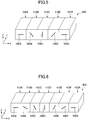
- FIG. 4 to FIG. 6 schematically illustrate another aspect of an assembly.
- an assembly 260 is made by arranging a total of five unmagnetized magnet materials 210A, 210B, 210C, 210D, and 210A along the array direction (X direction).
- the same unmagnetized magnet material 210A may be disposed at the left and right ends as illustrated in FIG. 4 .
- the unmagnetized magnet materials 210A to 210D have magnetization easy axes 240A to 240D oriented in different directions.
- the angle difference ⁇ of the magnetization easy axes 240 is 45 degrees in any one of the pairs of adjacent unmagnetized magnet materials.
- an assembly 360 is made by arranging a total of five unmagnetized magnet materials 310A, 310B, 310C, 310D, and 310A along the array direction (X direction).
- the same unmagnetized magnet material 310A may be disposed at the left and right ends as illustrated in FIG. 5 .
- the unmagnetized magnet materials 310A to 310D have magnetization easy axes 340A to 340D oriented in directions different from each other.
- the angle difference ⁇ among the magnetization easy axes 340A to 340D is 45 degrees in any one of the pairs of adjacent unmagnetized magnet materials.
- the assembly 360 differs from the assembly 260 in that the assembly 360 has, at the left and right ends, unmagnetized magnet materials 310A in which the magnetization easy axis 340 is oriented in the direction parallel to the array direction.
- an assembly 460 is made by arranging a total of seven unmagnetized magnet materials 410A, 410B, 410C, 410D, 410E, 410F, and 410A arranged along the array direction (X direction).
- the same unmagnetized magnet materials 410A may be disposed at the left and right ends.
- the unmagnetized magnet materials 410A to 410F have magnetization easy axes 440A to 440F oriented in directions different from each other.
- the angle difference ⁇ of the magnetization easy axis 440 is 30 degrees in each of the pairs of adjacent unmagnetized magnet materials.
- the angle difference ⁇ of the magnetization easy axes in adjacent pairs of unmagnetized magnet materials is not particularly limited as long as it is in the range of 30 degrees to 120 degrees.
- the number of unmagnetized magnet materials included in the assembly is not particularly limited as long as it is 3 or more.
- Fig. 7 schematically illustrates a cross section of a magnetization apparatus that can be used for magnetization process of an assembly.
- the magnetization apparatus 700 has a housing 702.
- the housing 702 has an accommodation part 704.
- a magnetization target body Q i.e., an assembly holding case 720 including an assembly, is placed in the accommodation part 704.
- the housing 702 includes two coil accommodation spaces 708A and 708B formed in parallel to a top view, i.e., the Y direction (i.e., a direction perpendicular to the page of this application) of FIG. 7 .
- Coils 710A and 710B are accommodated in the coil accommodation spaces 708A and 708B, respectively.
- the coil accommodation spaces 708A and 708B are filled with nonmagnetic resin.
- an assembly holding case 720 is arranged in the accommodation part 704 of the housing 702.
- a magnetization target body Q is placed in the assembly holding case 720.
- the magnetization target body Q may be, for example, the assembly 360 illustrated in FIG. 5 explained above.
- the magnetization target body Q does not necessarily need to be used by being accommodated in the assembly holding case 720.
- the magnetization target body Q may be directly accommodated in the accommodation part 704 of the housing 702.
- the housing 702 is made of a magnetic material and functions as a yoke.
- annular magnetic field B 1 is generated from the coil 710A. As illustrated in FIG. 7 , the annular magnetic field B 1 is generated substantially in a clockwise direction around the coil 710A. Likewise, with the applied current, the annular magnetic field B 2 is generated from the coil 710B. As illustrated in FIG. 7 , the annular magnetic field B 2 is generated substantially in a counterclockwise direction around the coil 710B.
- the coil 710A and the coil 710B are energized by charging a capacitor connected to the coil 710A and the coil 710B and discharging the electric charge charged in the capacitor.
- the annular magnetic field B 1 and the annular magnetic field B 2 are pulse magnetic fields generated by the pulse current.
- strong annular magnetic fields B 1 and B 2 can be stably generated from the coil 710A and the coil 710B without damaging the coil 710A and the coil 710B.
- the pulse width of the pulse current is, for example, in the range of 0.3 ms to 100 ms, preferably 0.5 ms to 10 ms. By setting the pulse width to the above range, a strong magnetic field can be applied while the heat generation of the coils is suppressed.
- the maximum current is, for example, in the range of 8 kA to 20 kA. It should be noted that the pulse current may be applied to the coil 710A and the coil 710B a plurality of times.
- a pulse magnetic field is applied to the magnetization target body Q by these annular magnetic fields B 1 and B 2 .
- the unmagnetized magnet materials contained in the magnetization target body Q are magnetized, and thus a magnetized body is obtained.
- the unmagnetized magnet materials 310A to 310D are magnetized in the magnetizing directions as illustrated in FIG. 8 .
- the magnetized magnets in a magnetized body 742, the magnetized magnets will be referred to as a magnet block 760A, a magnet block 760B, a magnet block 760C, a magnet block 760D, and a magnet block 760E, in an order along the X direction.
- the magnetization directions of the magnet blocks 760A to 760E will be referred to as 761A to 761E.
- the angle ⁇ formed by the magnetizing directions of adjacent magnet block pairs is defined as a magnetization direction angle difference ⁇ (where ⁇ is in a range of 0 degrees to 180 degrees).
- the magnetization direction angle difference ⁇ is 45 degrees in any pair.
- the magnetization direction of the magnet block includes a variation of about ⁇ 5 degrees. Therefore, in this application, the value of the magnetization direction angle difference ⁇ is assumed to include the range of ⁇ 5 degrees. Therefore, the magnetization direction angle difference of 45 degrees means a range in which ⁇ is 40 degrees to 50 degrees. The same applies to other values of magnetization direction angle differences.
- the direction of the magnetization is the direction having the N magnetic pole of the directions of the magnetization easy axis.
- FIG. 8 illustrates, for example, a case where the magnetization direction angle difference ⁇ is 45 degrees in the magnetized body 742.
- the magnetization direction angle difference ⁇ can be any given value selected from a range of 30 degrees to 120 degrees.
- a magnetized body 842 having a magnetization direction angle difference ⁇ of 90 degrees can be obtained as illustrated in FIG. 9 .
- a magnetized body 742 i.e., a Halbach magnet
- a bottom face 748 is a face yielding the maximum surface magnetic flux density (hereinafter referred to as "principal face (of Halbach magnet)").
- the bottom face 848 is a principal face.
- the size in the direction perpendicular to the principal face, i.e., to the bottom face 748, of the magnetized body 742 is, for example, in a range of 1 mm to 10 mm, more preferably in a range of 1 mm to 6 mm, still more preferably in a range of 5 mm or more and less than 6 mm.
- thickness is, for example, in a range of 1 mm to 10 mm, more preferably in a range of 1 mm to 6 mm, still more preferably in a range of 5 mm or more and less than 6 mm.
- the magnetization rate of each of the magnet blocks constituting the magnetized body 742 can be increased (for example, 95% or more).
- the magnetization rate By setting the magnetization rate to 95% or more, the squareness is improved, and this can make it less likely for the magnet block to demagnetize.
- the inventor and the like of the present application has discovered that, by using the magnetization apparatus 700 as illustrated in FIG. 7 to apply a pulse magnetic field to the magnetization target body Q, magnetization can be performed even in a manner in which the magnetization directions are greatly different in a pair of adjacent unmagnetized magnet materials.
- An example of manufacturing a Halbach magnet according to the method of performing the magnetization after the assembling has never been expected to date, and the result of the present application is surprising.
- the Halbach magnet in the first manufacturing method, can be manufactured by performing the magnetization process on the magnetization target body Q later.
- the first manufacturing method can avoid the problem of deterioration in the precision of assembly due to the influence of the above-described repulsions and/or attractions of the magnet blocks, and can relatively easily manufacture a Halbach magnet having desired characteristics.
- the second manufacturing method includes:
- the second manufacturing method is fundamentally similar to the first manufacturing method explained above. However, in the second manufacturing method, a magnetization apparatus different from the magnetization apparatus 700 used in the first manufacturing method is used in step S220.
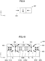
- FIG. 10 schematically illustrates a magnetization apparatus (second magnetization apparatus) that can be used in step S220 of the second manufacturing method.
- a second magnetization apparatus 900 has a housing 902.
- the housing 902 has a non-magnetic frame member 903 in the upper part, and an accommodation part 904 is formed in the upper part of the housing 902 by the frame member 903.
- a magnetization target body i.e., an assembly holding case 920 including an assembly, is placed in the accommodation part 904.
- Coil accommodation spaces 908A, 908B, and 908C are formed in parallel with each other along a top view, i.e., the Y direction (i.e., a direction perpendicular to the page of this application) of FIG. 10 .
- Coils 910A and 910C are accommodated in the coil accommodation spaces 908A and 908C, respectively.
- two pairs of coils i.e., a coil 910B1 (upper and lower four coils on the left-hand side) and a coil 910B2 (upper and lower four coils on the right-hand side) are accommodated in the central coil accommodation space 908B.
- the space between the coil 910B1 and the coil 910B2 is an air layer, in which the relative permeability is low, and accordingly, it is difficult for magnetic flux to pass through this space.
- the gap of the coil accommodation space 908B can be filled with non-magnetic resin. The same applies to the coil accommodation spaces 908A and 908C.
- an assembly holding case 920 is arranged in the accommodation part 904 of the housing 902.
- a magnetization target body Q is placed in the assembly holding case 920.
- the magnetization target body Q may be, for example, the assembly 260 illustrated in FIG. 4 explained above.
- the magnetization target body Q does not necessarily need to be accommodated in the assembly holding case 920.
- the magnetization target body Q may be directly accommodated in the accommodation part 904 of the housing 902.
- the housing 902 is made of a magnetic material and functions as a yoke.
- annular magnetic field B 1 is generated from the coil 910A. As illustrated in FIG. 10 , the annular magnetic field B 1 is generated substantially in a counterclockwise direction around the coil 910A. Likewise, with the applied current, the annular magnetic field B 2 is generated from the coils 910B1, B2. As illustrated in FIG. 10 , the annular magnetic field B 2 is generated substantially in a clockwise direction around the two coils 910B1, 910B2. Likewise, with the applied current, the annular magnetic field B 3 is generated from the coil 910C. As illustrated in FIG. 10 , the annular magnetic field B 3 is generated substantially in a counterclockwise direction around the coil 910C.
- the coils 910A, 910B1, 901B2, and the coil 910C are energized by generating a pulse current using a capacitor with a high charge capacitance as explained above.
- the annular magnetic fields B 1 to B 3 are pulse magnetic fields.
- strong annular magnetic fields B 1 to B 3 can be stably generated from the coils 910A, 910B1, 901B2, and 910C without damaging the coils 910A, 910B1, 901B2, and 910C.
- the pulse width of the pulse current is, for example, in the range of 0.3 ms to 100 ms, preferably 0.5 ms to 10 ms.
- the maximum current is, for example, in the range of 8 kA to 20 kA. It should be noted that the pulse current may be applied to the coils 910A, 910B1, 901B2, and 910C a plurality of times.
- a pulse magnetic field is applied to the magnetization target body Q by these annular magnetic fields B 1 to B 3 .
- the unmagnetized magnet materials contained in the magnetization target body Q are magnetized, and thus a magnetized body is obtained.
- the unmagnetized magnet materials 210A to 210D are magnetized into magnets magnetized in the magnetizing directions as illustrated in FIG. 11 .
- the magnetized magnets will be referred to as a magnet block 960A, a magnet block 960B, a magnet block 960C, a magnet block 960D, and a magnet block 960E, in an order along the X direction.
- the magnetization directions of the magnet blocks 960A to 960E will be referred to as 961A to 961E.
- an angle formed by the magnetizing directions of adjacent magnet block pairs i.e., a magnetization direction angle difference ⁇
- this magnetization direction angle difference ⁇ includes a variation of about ⁇ 5 degrees.
- the bottom face 948 is a face yielding the maximum surface magnetic flux density (i.e., a principal face of a Halbach magnet).
- the size in the direction perpendicular to the principal face of the magnetized body 942 ("thickness" of the magnetized body 942) is, for example, in a range of 1 mm to 10 mm, more preferably in a range of 1 mm to 6 mm, still more preferably in a range of 1.5 mm to 4 mm.
- the thickness By setting the thickness to 1.5 mm or more, the maximum value of the surface magnetic flux density on the principal face of the magnetized body 942 can be increased.
- the magnetization rate of each of the magnets constituting the magnetized body 942 can be 95% or more. By setting the magnetization rate to 95% or more, the squareness is improved, and this can make it less likely for the magnet to demagnetize.
- the magnetized body 942 is configured such that the bottom face 948 has two magnetic poles (the magnet 960A and the magnet 960E).
- FIG. 11 illustrates, for example, a case where the magnetization direction angle difference ⁇ is 45 degrees in the magnetized body 942.
- the magnetization direction angle difference ⁇ can be any given value selected from a range of 30 degrees to 120 degrees.
- a magnetized body having a larger magnetization direction angle difference ⁇ can be obtained in a case where the distance between the three coil accommodation spaces 908A, 908B, and 908C is brought to be closer. Conversely, in a case where the distance between the three coil accommodation spaces 908A, 908B, and 908C is brought to be farther, a magnetized body having a smaller magnetization direction angle difference ⁇ can be obtained.
- a magnetized body 942 i.e., a Halbach magnet
- a magnetized body having a magnetization direction angle difference ⁇ of about 30 degrees can be formed by magnetizing the assembly 460 as illustrated in FIG. 6 .
- At least a part of the method for manufacturing a Halbach magnet explained in the present application can also be applied as a magnetizing method for magnetizing an unmagnetized magnet.
- a Halbach magnets was manufactured by the following method.
- three sintered neodymium magnets (manufactured by Neomag Co., Ltd.) were prepared in which the magnetization easy axes of magnetic particles were oriented in a single direction.
- magnets were demagnetized by being heated and then processed into the specified dimensions to obtain the first to third unmagnetized magnet materials.
- the first unmagnetized magnet material was substantially in a cuboid shape, and had dimensions of 7 mm long ⁇ 6.7 mm wide ⁇ 2 mm high.
- the magnetization easy axis of the magnetic particles was oriented along the height direction (i.e., direction parallel to the side of 2 mm).
- the second unmagnetized magnet material had the same dimensions as the first unmagnetized magnet material.
- the magnetization easy axis of the magnetic particles was oriented along the horizontal direction (i.e., direction parallel to the side of 6.7 mm).
- the third unmagnetized magnet material was the same as the first unmagnetized magnet material.
- the unmagnetized magnet materials were arrayed in a row in an order of the first unmagnetized magnet material, the second unmagnetized magnet material, and the third unmagnetized magnet material, with the faces of 7 mm ⁇ 2 mm being bonding target faces.
- the unmagnetized magnet materials were bonded via an epoxy resin to form an assembly.
- the assembly was magnetized using the second magnetization apparatus 900 as illustrated in FIG. 10 .
- the capacitance of the capacitor used was 1000 ⁇ F, and the charging voltage was 1400V.
- a pulse current of up to 14.1 kA having a pulse width of 0.7 ms or less was applied to the coils 910A to 910C.
- an annular pulse magnetic field was generated around the coils 910A to 910C, and the assembly was magnetized.
- Fig. 12 schematically illustrates a form of a Halbach magnet obtained after magnetization.
- a Halbach magnet 1100 includes three magnet blocks 1110, 1120, and 1130.
- the magnetization direction was the positive direction of the Z axis.
- the magnetization direction was the positive direction of the X axis.
- the magnetization direction was the negative direction of the Z axis. Therefore, the magnetization direction angle difference ⁇ was 90 degrees (where 0 degrees ⁇ ⁇ ⁇ 180 degrees holds).
- the bottom face 1105 had the strongest surface magnetic flux density, and therefore, the bottom face 1105 served as the principal face.
- the Halbach magnet 1100 with two magnetic poles on the principal face was manufactured.
- a Halbach magnet was prepared in the same manner as in Example 1.
- Example 2 the dimensions of each unmagnetized magnet material were changed to 7 mm long ⁇ 6.7 mm wide ⁇ 3 mm high.
- the fabrication conditions other than the above are the same as those in Example 1.
- a Halbach magnet was made according to a method similar to Example 1.
- Example 3 the dimensions of each unmagnetized magnet material were changed to 7 mm long ⁇ 6.7 mm wide ⁇ 3.5 mm high.
- the fabrication conditions other than the above are the same as those in Example 1.
- a Halbach magnet was made according to a method similar to Example 1.
- Example 4 the dimensions of each unmagnetized magnet material were changed to 7 mm long ⁇ 6.7 mm wide ⁇ 6 mm high.
- the fabrication conditions other than the above are the same as those in Example 1.
- a Halbach magnet was made according to a method similar to Example 1.
- Example 5 five unmagnetized magnet materials were bonded to form an assembly.
- the dimensions of each unmagnetized magnet material were 15 mm long ⁇ 4 mm wide ⁇ 4 mm high.
- the assembly was magnetized using the second magnetization apparatus 700 as illustrated in FIG. 7 .
- the capacitance of the capacitor used was 1000 ⁇ F, and the charging voltage was 1400V.
- a pulse current of up to 14.1 kA having a pulse width of 0.7 ms or less was applied to the coils 910A to 910C.
- an annular pulse magnetic field was generated around the coils 710A to 710B, and the assembly was magnetized.
- a Halbach magnet was made according to a method similar to Example 5.
- Example 6 in the assembly, the orientations of the magnetization easy axes in the unmagnetized magnet materials were as illustrated in FIG. 4 .
- this Halbach magnet 1200 includes five magnet blocks 1210, 1220, 1230, 1240, and 1250.
- the magnetization direction was the positive direction of the Z axis. Then, the magnetization direction of each of the magnet blocks was changed 45 degrees in the clockwise direction along the array direction. In the rightmost magnet block 1250, the magnetization direction was the negative direction of the Z axis. Therefore, in this Halbach magnet 1200, the magnetization direction angle difference ⁇ was 45 degrees (however, 0 degrees ⁇ ⁇ ⁇ 180 degrees holds).
- the bottom face 1205 had the strongest surface magnetic flux density, and therefore, the bottom face 1205 served as the principal face.
- Example 6 the Halbach magnet 1200 with two magnetic poles on the principal face was manufactured.
- a Halbach magnet was made according to a method similar to Example 1.
- Example 7 the first and third unmagnetized magnet materials were 7 mm long ⁇ 8.0 mm wide ⁇ 4 mm high, and the second unmagnetized magnet material was 7 mm long ⁇ 4.0 mm wide ⁇ 4 mm high.
- the ratio of the lengths in the width direction (horizontal direction) between the magnet pieces is 2:1:2.
- the fabrication conditions other than the above are the same as those in Example 1.
- a Halbach magnet was made according to a method similar to Example 1.
- Example 8 however, the first and third unmagnetized magnet materials were 7 mm long ⁇ 8.0 mm wide ⁇ 6 mm high, and the second unmagnetized magnet material was 7 mm long ⁇ 4.0 mm wide ⁇ 6 mm high.
- the ratio of the lengths in the width direction (horizontal direction) between the magnet pieces is 2:1:2.
- the fabrication conditions other than the above are the same as those in Example 1.
- a Halbach magnet was made according to a method similar to Example 1.
- Example 9 however, the first and third unmagnetized magnet materials were 7 mm long ⁇ 5.0 mm wide ⁇ 4 mm high, and the second unmagnetized magnet material was 7 mm long ⁇ 10.0 mm wide ⁇ 4 mm high. In other words, the ratio of the lengths in the width direction (horizontal direction) between the magnet pieces is 1:2:1.
- the fabrication conditions other than the above are the same as those in Example 1.
- a Halbach magnet was made according to a method similar to Example 1.
- Example 10 the first and third unmagnetized magnet materials were 7 mm long ⁇ 5.0 mm wide ⁇ 6 mm high, and the second unmagnetized magnet material was 7 mm long ⁇ 10.0 mm wide ⁇ 6 mm high.
- the ratio of the lengths in the width direction (horizontal direction) between the magnet pieces is 1:2:1.
- the fabrication conditions other than the above are the same as those in Example 1.
- a Halbach magnet was made according to a method similar to Example 1.
- Example 11 however, the first and third unmagnetized magnet materials were 7 mm long ⁇ 5.0 mm wide ⁇ 8 mm high, and the second unmagnetized magnet material was 7 mm long ⁇ 10.0 mm wide ⁇ 8 mm high. In other words, the ratio of the lengths in the width direction (horizontal direction) between the magnet pieces is 1:2:1.
- the fabrication conditions other than the above are the same as those in Example 1.
- a Halbach magnet was made according to a method similar to Example 1.
- Example 12 however, the first and third unmagnetized magnet materials were 7 mm long ⁇ 5.0 mm wide ⁇ 10 mm high, and the second unmagnetized magnet material was 7 mm long ⁇ 10.0 mm wide ⁇ 10 mm high. In other words, the ratio of the lengths in the width direction (horizontal direction) between the magnet pieces is 1:2:1.
- the fabrication conditions other than the above are the same as those in Example 1.
- a Halbach magnet was made according to a method similar to Example 1.
- Example 21 the dimensions of each unmagnetized magnet material were changed to 7 mm long ⁇ 6.7 mm wide ⁇ 8 mm high.
- the fabrication conditions other than the above are the same as those in Example 1.
- a Halbach magnet was made according to a method similar to Example 1.
- Example 22 however, the first and third unmagnetized magnet materials were 7 mm long ⁇ 8.0 mm wide ⁇ 8 mm high, and the second unmagnetized magnet material was 7 mm long ⁇ 4.0 mm wide ⁇ 8 mm high.
- the ratio of the lengths in the width direction (horizontal direction) between the magnet pieces is 2:1:2.
- the fabrication conditions other than the above are the same as those in Example 1.
- a Halbach magnet was made according to a method similar to Example 1.
- Example 23 however, the first and third unmagnetized magnet materials were 7 mm long ⁇ 8.0 mm wide ⁇ 10 mm high, and the second unmagnetized magnet material was 7 mm long ⁇ 4.0 mm wide ⁇ 10 mm high.
- the ratio of the lengths in the width direction (horizontal direction) between the magnet pieces is 2:1:2.
- the fabrication conditions other than the above are the same as those in Example 1.
- the adhesives were removed, and the magnet blocks were separated. Also, the magnetization rates were evaluated using the obtained magnet blocks (hereinafter referred to as "separated magnets").
- the magnetization rates of the separated magnets were measured according to the following method using a Helmholtz coil device.
- FIG. 14 schematically illustrates a configuration of a Helmholtz coil device.
- a Helmholtz coil device 1300 includes a first coil 1310 at an upper side and a second coil 1320 at a lower side.
- the first coil 1310 and the second coil 1320 are arranged in parallel to each other so as to have the same central axis C.
- the diameters of the first coil 1310 and the second coil 1320 are both 70 mm, and the number of turns of the first coil 1310 and the second coil 1320 are both 50 times.
- a distance d between the coils 1310 and 1320 is 35 mm.
- a measurement target body (separated magnet) S is disposed at an intermediate position between the first coil 1310 and the second coil 1320 on the central axis C of the first coil 1310 and the second coil 1320. Also, the orientation directions of the magnetization easy axes of the measurement target body are arranged to be in parallel to the central axis C.
- the measurement target body S is moved along the central axis C in the direction indicated by the arrow and pulled out across the plane formed by the second coil 1320. With this action, an induced voltage V is generated in the first coil 1310 and the second coil 1320.
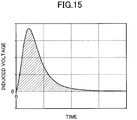
- FIG. 15 schematically illustrates an induced voltage V generated in the first coil 1310 and the second coil 1320 by the pull-out action of the measurement target body S.
- the horizontal axis denotes a time change when the measurement target body S is pulled out
- the vertical axis denotes the induced voltage V.
- the total magnetic flux amount R 1 of the measurement target body S is measured.
- the total magnetic flux amount R 1 and the total magnetic flux amount R 2 are each the average of three measurement results.
- a field of "average” indicates an average value of the magnetization rates R obtained from the separated magnets retrieved from a Halbach magnet.
- Example 1 From the results in Table 1, it can be seen that in Example 1 to Example 12, high magnetization rates were obtained from the separated magnets in any Example. In particular, in Example 5, Example 7, and Example 9 to Example 10, the average magnetization rates R of the separated magnets were over 98%, which is extremely high.
- the Halbach magnets can be manufactured properly even if the magnetization directions are greatly different between adjacent magnet blocks such that the magnetization direction angle difference ⁇ exceeds 45 degrees.
- the magnetization rate has a great influence not only on the strength of the magnetic force but also on the squareness that represents the resistance to demagnetization.
- the magnetization rate is less than 95%, the squareness is greatly reduced. Therefore, it is preferable that the magnetization rates of all the magnet blocks forming the Halbach magnet exceed 95%.
- the ease of magnetization is greatly influenced not only by the thickness of the magnet, but also by the ratio of the lengths in the width direction of the unmagnetized magnet materials (for example, the sizes in the X direction in FIG. 12 , FIG. 13 , and the like).
- a ratio (W1:W2) between a length W1 in the width direction of a magnet block having a magnetization easy axis oriented in a direction perpendicular to a face yielding a maximum surface magnetic flux density and a length W2 in the width direction of a magnet block having a magnetization easy axis oriented in a direction perpendicular to the face yielding the maximum surface magnetic flux density is preferably in a range of 1:2 to 2:1.
- a length W2 in the width direction of a magnet block having a magnetization easy axis oriented in a direction parallel to the face yielding the maximum surface magnetic flux density with respect to a length W1 in the width direction of a magnet block having a magnetization easy axis oriented in a direction perpendicular to a face yielding a maximum surface magnetic flux density, i.e., W2/W1, may be in a range of more than 1 and equal to or less than 2.
- a ratio (W1:W2) between a length W1 in the width direction of a magnet block having a magnetization easy axis oriented in a direction perpendicular to a face yielding a maximum surface magnetic flux density and a length W2 in the width direction of a magnet block having a magnetization easy axis oriented in a direction parallel to the face yielding the maximum surface magnetic flux density may be in a range of 2:1 to 1:1.
- the ratio between the length W1 in the width direction of the leftmost magnet block and the length W2 in the width direction of the center magnet block is 1:2.
- a significantly higher magnetization rate can be obtained as compared to the case where the ratio W1:W2 is 1:1 as in Example 4.
Landscapes
- Engineering & Computer Science (AREA)
- Power Engineering (AREA)
- Manufacturing & Machinery (AREA)
- Physics & Mathematics (AREA)
- Electromagnetism (AREA)
- Mechanical Engineering (AREA)
- Permanent Field Magnets Of Synchronous Machinery (AREA)
- Hard Magnetic Materials (AREA)
Applications Claiming Priority (2)
| Application Number | Priority Date | Filing Date | Title |
|---|---|---|---|
| JP2017104929 | 2017-05-26 | ||
| PCT/JP2018/020193 WO2018216805A1 (ja) | 2017-05-26 | 2018-05-25 | 磁石の製造方法および磁石の着磁方法 |
Publications (2)
| Publication Number | Publication Date |
|---|---|
| EP3633698A1 true EP3633698A1 (de) | 2020-04-08 |
| EP3633698A4 EP3633698A4 (de) | 2021-02-24 |
Family
ID=64396632
Family Applications (1)
| Application Number | Title | Priority Date | Filing Date |
|---|---|---|---|
| EP18805587.5A Withdrawn EP3633698A4 (de) | 2017-05-26 | 2018-05-25 | Magnetherstellungsverfahren und magnetmagnetisierungsverfahren |
Country Status (6)
| Country | Link |
|---|---|
| US (1) | US11623276B2 (de) |
| EP (1) | EP3633698A4 (de) |
| JP (1) | JP7274266B2 (de) |
| KR (1) | KR20200010270A (de) |
| CN (1) | CN110678943B (de) |
| WO (1) | WO2018216805A1 (de) |
Cited By (1)
| Publication number | Priority date | Publication date | Assignee | Title |
|---|---|---|---|---|
| EP3923305A1 (de) * | 2020-06-10 | 2021-12-15 | General Electric Renovables España S.L. | Magnetisierung von permanentmagneten |
Families Citing this family (33)
| Publication number | Priority date | Publication date | Assignee | Title |
|---|---|---|---|---|
| US11170924B2 (en) * | 2017-03-02 | 2021-11-09 | Microsoft Technology Licensing, Llc | Computing devices, removable support devices, and methods of use |
| US11843334B2 (en) | 2017-07-13 | 2023-12-12 | Denso Corporation | Rotating electrical machine |
| CN113991958A (zh) | 2017-07-21 | 2022-01-28 | 株式会社电装 | 旋转电机 |
| DE112018006699T5 (de) | 2017-12-28 | 2020-09-10 | Denso Corporation | Rotierende elektrische Maschine |
| JP6922868B2 (ja) | 2017-12-28 | 2021-08-18 | 株式会社デンソー | 回転電機システム |
| JP6939750B2 (ja) | 2017-12-28 | 2021-09-22 | 株式会社デンソー | 回転電機 |
| DE112018006717T5 (de) | 2017-12-28 | 2020-09-10 | Denso Corporation | Rotierende elektrische Maschine |
| CN111512519B (zh) | 2017-12-28 | 2022-10-11 | 株式会社电装 | 旋转电机 |
| JP7006541B2 (ja) * | 2017-12-28 | 2022-01-24 | 株式会社デンソー | 回転電機 |
| DE102019210177B4 (de) * | 2019-07-10 | 2021-05-20 | Fraunhofer-Gesellschaft zur Förderung der angewandten Forschung e.V. | Verfahren zum Herstellen einer gegenläufig magnetisierten Magnetstruktur |
| JP7358839B2 (ja) * | 2019-08-22 | 2023-10-11 | 株式会社デンソー | 点火コイル |
| CN111009407A (zh) * | 2019-12-31 | 2020-04-14 | 杭州智见控股集团有限公司 | 一种海尔贝克阵列磁体组件的组装工艺方法 |
| DE112020006839T5 (de) | 2020-03-05 | 2022-12-15 | Denso Corporation | Rotierende elektrische Maschinen |
| CN112530658B (zh) * | 2020-11-27 | 2022-09-27 | 杭州智见控股集团有限公司 | 一种海尔贝克阵列磁体组件的一体充磁方法 |
| CN112712987A (zh) * | 2020-12-09 | 2021-04-27 | 宁波韵升股份有限公司 | 一种海尔贝克磁体的制备方法 |
| CN112863807B (zh) * | 2021-01-12 | 2023-03-31 | 福建省长汀金龙稀土有限公司 | 一种产生非平行磁场的方法及装置 |
| EP4270424A4 (de) * | 2021-01-20 | 2024-06-12 | Samsung Electronics Co., Ltd. | Elektronische vorrichtung mit array-magnet und verfahren zur herstellung eines array-magneten |
| JP2022182315A (ja) * | 2021-05-28 | 2022-12-08 | トヨタ自動車株式会社 | ハルバッハ磁石配列体を製造する方法 |
| JP7609000B2 (ja) * | 2021-07-27 | 2025-01-07 | トヨタ自動車株式会社 | ハルバッハ磁石配列体を製造する方法、及びハルバッハ磁石配列体 |
| CN113903542B (zh) * | 2021-09-02 | 2022-05-20 | 华中科技大学 | 一种直线型Halbach阵列的充磁方法及装置 |
| JP7647531B2 (ja) * | 2021-12-16 | 2025-03-18 | トヨタ自動車株式会社 | 着磁方法及び着磁装置 |
| JP7748869B2 (ja) | 2021-12-17 | 2025-10-03 | 朝日インテック株式会社 | 着磁装置 |
| JP7632324B2 (ja) * | 2022-01-25 | 2025-02-19 | トヨタ自動車株式会社 | 着磁方法及び着磁装置 |
| CN114551027A (zh) * | 2022-03-31 | 2022-05-27 | 华中科技大学 | 一种海尔贝克式磁化器及桥梁缆索缺陷检测装置 |
| KR102642299B1 (ko) * | 2022-04-14 | 2024-03-04 | 주식회사 마그트론 | 할바흐 배열 마그네트 제조 방법 |
| CN115360005B (zh) * | 2022-08-05 | 2024-12-27 | 宁波科田磁业股份有限公司 | 一种海尔贝克磁体定型组装结构及其组装方法 |
| KR102549323B1 (ko) * | 2022-12-23 | 2023-06-29 | 주식회사 노바텍 | 자석 조립체 |
| KR102549322B1 (ko) * | 2022-12-23 | 2023-06-29 | 주식회사 노바텍 | 자석 조립체 및 그 제조방법 |
| US12087335B2 (en) * | 2022-12-27 | 2024-09-10 | Western Digital Technologies, Inc. | In-situ install of cross-flux magnet in voice coil motor actuator |
| JP7443585B1 (ja) | 2023-01-23 | 2024-03-05 | 東芝エレベータ株式会社 | 着磁装置及び着磁方法 |
| US20250104895A1 (en) * | 2023-09-27 | 2025-03-27 | Apple Inc. | Mim magnets |
| CN118100578B (zh) * | 2024-04-28 | 2024-07-26 | 中国人民解放军海军工程大学 | 一种基于振动主动控制电磁作动器的磁组件结构 |
| CN119207993B (zh) * | 2024-11-29 | 2025-03-25 | 包头市英思特稀磁新材料股份有限公司 | 一种磁组件粘接方法 |
Family Cites Families (18)
| Publication number | Priority date | Publication date | Assignee | Title |
|---|---|---|---|---|
| CS213709B1 (en) * | 1979-03-13 | 1982-04-09 | Vaclav Landa | Anizotropous permanent magnets |
| JPH02290003A (ja) | 1988-08-18 | 1990-11-29 | Hitachi Metals Ltd | 異方性希土類永久磁石およびその製造方法ならびに異方性永久磁石成形用金型 |
| US5049053A (en) | 1988-08-18 | 1991-09-17 | Hitachi Metals, Ltd. | Metal mold for molding anisotropic permanent magnets |
| JPH06302417A (ja) | 1993-04-15 | 1994-10-28 | Seiko Epson Corp | 永久磁石およびその製造方法 |
| JP3296674B2 (ja) * | 1995-02-02 | 2002-07-02 | 理化学研究所 | シンクロトロン放射における挿入光源 |
| JP3249930B2 (ja) | 1997-04-14 | 2002-01-28 | 信越化学工業株式会社 | 挿入光源 |
| JP2004072820A (ja) | 2002-08-01 | 2004-03-04 | Yaskawa Electric Corp | Acモータの回転子の着磁治具及びそれを用いた製造方法 |
| JP2010050440A (ja) | 2008-07-23 | 2010-03-04 | Hitachi Metals Ltd | R−Fe−B系焼結磁石ユニットおよびそれを用いたリニアモータ用磁気回路並びにそれらの製造方法 |
| JP2010130818A (ja) * | 2008-11-28 | 2010-06-10 | Daikin Ind Ltd | 界磁子の製造方法 |
| US20120091832A1 (en) | 2009-09-21 | 2012-04-19 | Soderberg Rod F | Matrix material comprising magnetic particles for use in hybrid and electric vehicles |
| JP2013243886A (ja) | 2012-05-22 | 2013-12-05 | Nitto Denko Corp | 永久磁石モータ、永久磁石モータの製造方法及び永久磁石 |
| JP6343663B2 (ja) * | 2013-05-23 | 2018-06-13 | エーエスエムエル ネザーランズ ビー.ブイ. | リソグラフィ装置およびデバイス製造方法 |
| CN105280324B (zh) | 2014-07-18 | 2018-08-24 | 日立金属株式会社 | 磁铁单元和磁铁单元的制造方法 |
| JP2016029880A (ja) | 2014-07-18 | 2016-03-03 | 日立金属株式会社 | 磁石ユニット及び磁石ユニットの製造方法 |
| JP2016072457A (ja) * | 2014-09-30 | 2016-05-09 | 住友金属鉱山株式会社 | 異方性ボンド磁石の着磁方法 |
| JP6596798B2 (ja) * | 2014-10-21 | 2019-10-30 | 国立研究開発法人理化学研究所 | アンジュレータ磁石列及びアンジュレータ |
| CN104409129B (zh) * | 2014-11-17 | 2017-02-22 | 中国科学院上海微系统与信息技术研究所 | 一种波荡器 |
| JP6141951B1 (ja) | 2015-12-09 | 2017-06-07 | 株式会社アマダホールディングス | 丸鋸盤 |
-
2018
- 2018-05-25 US US16/616,653 patent/US11623276B2/en active Active
- 2018-05-25 CN CN201880034468.9A patent/CN110678943B/zh active Active
- 2018-05-25 WO PCT/JP2018/020193 patent/WO2018216805A1/ja not_active Ceased
- 2018-05-25 EP EP18805587.5A patent/EP3633698A4/de not_active Withdrawn
- 2018-05-25 KR KR1020197034562A patent/KR20200010270A/ko not_active Ceased
- 2018-05-25 JP JP2018100231A patent/JP7274266B2/ja active Active
Cited By (2)
| Publication number | Priority date | Publication date | Assignee | Title |
|---|---|---|---|---|
| EP3923305A1 (de) * | 2020-06-10 | 2021-12-15 | General Electric Renovables España S.L. | Magnetisierung von permanentmagneten |
| US11923117B2 (en) | 2020-06-10 | 2024-03-05 | General Electric Renovables Espana, S.L. | Magnetizing permanent magnets |
Also Published As
| Publication number | Publication date |
|---|---|
| KR20200010270A (ko) | 2020-01-30 |
| JP7274266B2 (ja) | 2023-05-16 |
| WO2018216805A1 (ja) | 2018-11-29 |
| CN110678943B (zh) | 2022-04-26 |
| EP3633698A4 (de) | 2021-02-24 |
| US20200282463A1 (en) | 2020-09-10 |
| CN110678943A (zh) | 2020-01-10 |
| US11623276B2 (en) | 2023-04-11 |
| JP2018201018A (ja) | 2018-12-20 |
Similar Documents
| Publication | Publication Date | Title |
|---|---|---|
| EP3633698A1 (de) | Magnetherstellungsverfahren und magnetmagnetisierungsverfahren | |
| EP3125405B1 (de) | Permanentmagnetanordnung und motor | |
| EP0591542B1 (de) | Magnetfeld-generator zur bilddarstellung mittels kernresonanz | |
| US10003228B2 (en) | Interior permanent magnet machine with axially varying permanent magnet size | |
| CN102576595B (zh) | 磁化装置、永磁电动机的制造方法 | |
| US20090237080A1 (en) | Magnetic field generator and nuclear magnetic resonance device provided with the magnetic field generator | |
| US9646751B2 (en) | Arcuate magnet having polar-anisotropic orientation, and method and molding die for producing it | |
| JP2013126281A (ja) | 界磁子の製造方法及び界磁子用の端板 | |
| EP2767992B1 (de) | Herstellungsverfahren für ein magnetisches pulver zur herstellung eines sinterkörpers eines seltenerd-magnetvorläufers | |
| US11784550B2 (en) | Permanent field magnet, manufacturing method, and linear motor | |
| US20060103254A1 (en) | Permanent magnet rotor | |
| EP3032554B1 (de) | Herstellungsverfahren für einen unterteilten nichtmagnetisierten dauermagenten | |
| EP3213357B1 (de) | Elektrische maschinen | |
| CN110829758A (zh) | 磁铁构造体,磁铁构造体的制造方法以及旋转电机的制造方法 | |
| JP2024047599A (ja) | 着磁装置及び着磁方法 | |
| CN203352411U (zh) | 直线滑动器 | |
| JP2019193404A (ja) | 着磁装置、磁石構造体の製造方法および回転電機の製造方法 | |
| JP4697581B2 (ja) | 永久磁石体及びその製造方法 | |
| EP4095870B1 (de) | Verfahren zur herstellung einer halbach-magnetanordnung | |
| CN111327135B (zh) | 永磁铁和旋转电机 | |
| JP3150196B2 (ja) | Mri用磁界発生装置 | |
| JP3445303B2 (ja) | Mri用磁界発生装置 | |
| JPH09117431A (ja) | Mri用磁界発生装置 | |
| JP2017103312A (ja) | 磁石の製造方法 |
Legal Events
| Date | Code | Title | Description |
|---|---|---|---|
| STAA | Information on the status of an ep patent application or granted ep patent |
Free format text: STATUS: THE INTERNATIONAL PUBLICATION HAS BEEN MADE |
|
| PUAI | Public reference made under article 153(3) epc to a published international application that has entered the european phase |
Free format text: ORIGINAL CODE: 0009012 |
|
| STAA | Information on the status of an ep patent application or granted ep patent |
Free format text: STATUS: REQUEST FOR EXAMINATION WAS MADE |
|
| 17P | Request for examination filed |
Effective date: 20191125 |
|
| AK | Designated contracting states |
Kind code of ref document: A1 Designated state(s): AL AT BE BG CH CY CZ DE DK EE ES FI FR GB GR HR HU IE IS IT LI LT LU LV MC MK MT NL NO PL PT RO RS SE SI SK SM TR |
|
| AX | Request for extension of the european patent |
Extension state: BA ME |
|
| DAV | Request for validation of the european patent (deleted) | ||
| DAX | Request for extension of the european patent (deleted) | ||
| REG | Reference to a national code |
Ref country code: DE Ref legal event code: R079 Free format text: PREVIOUS MAIN CLASS: H01F0007020000 Ipc: H01F0041020000 |
|
| A4 | Supplementary search report drawn up and despatched |
Effective date: 20210121 |
|
| RIC1 | Information provided on ipc code assigned before grant |
Ipc: H01F 7/02 20060101ALI20210115BHEP Ipc: H01F 13/00 20060101ALI20210115BHEP Ipc: H02K 15/03 20060101ALI20210115BHEP Ipc: H01F 41/02 20060101AFI20210115BHEP |
|
| STAA | Information on the status of an ep patent application or granted ep patent |
Free format text: STATUS: EXAMINATION IS IN PROGRESS |
|
| 17Q | First examination report despatched |
Effective date: 20230703 |
|
| STAA | Information on the status of an ep patent application or granted ep patent |
Free format text: STATUS: THE APPLICATION IS DEEMED TO BE WITHDRAWN |
|
| 18D | Application deemed to be withdrawn |
Effective date: 20231114 |