EP3633703A1 - Verriegelungsmodul eines aktivierungssystems für eine elektrische schaltvorrichtung - Google Patents
Verriegelungsmodul eines aktivierungssystems für eine elektrische schaltvorrichtung Download PDFInfo
- Publication number
- EP3633703A1 EP3633703A1 EP19199499.5A EP19199499A EP3633703A1 EP 3633703 A1 EP3633703 A1 EP 3633703A1 EP 19199499 A EP19199499 A EP 19199499A EP 3633703 A1 EP3633703 A1 EP 3633703A1
- Authority
- EP
- European Patent Office
- Prior art keywords
- module according
- lever
- shaft
- module
- arming
- Prior art date
- Legal status (The legal status is an assumption and is not a legal conclusion. Google has not performed a legal analysis and makes no representation as to the accuracy of the status listed.)
- Granted
Links
Images




Classifications
-
- H—ELECTRICITY
- H01—ELECTRIC ELEMENTS
- H01H—ELECTRIC SWITCHES; RELAYS; SELECTORS; EMERGENCY PROTECTIVE DEVICES
- H01H5/00—Snap-action arrangements, i.e. in which during a single opening operation or a single closing operation energy is first stored and then released to produce or assist the contact movement
- H01H5/04—Energy stored by deformation of elastic members
- H01H5/14—Energy stored by deformation of elastic members by twisting of torsion members
- H01H5/16—Energy stored by deformation of elastic members by twisting of torsion members with auxiliary means for temporarily holding parts until torsion member is sufficiently strained
-
- H—ELECTRICITY
- H01—ELECTRIC ELEMENTS
- H01H—ELECTRIC SWITCHES; RELAYS; SELECTORS; EMERGENCY PROTECTIVE DEVICES
- H01H3/00—Mechanisms for operating contacts
- H01H3/22—Power arrangements internal to the switch for operating the driving mechanism
- H01H3/30—Power arrangements internal to the switch for operating the driving mechanism using spring motor
- H01H3/3031—Means for locking the spring in a charged state
-
- F—MECHANICAL ENGINEERING; LIGHTING; HEATING; WEAPONS; BLASTING
- F16—ENGINEERING ELEMENTS AND UNITS; GENERAL MEASURES FOR PRODUCING AND MAINTAINING EFFECTIVE FUNCTIONING OF MACHINES OR INSTALLATIONS; THERMAL INSULATION IN GENERAL
- F16H—GEARING
- F16H33/00—Gearings based on repeated accumulation and delivery of energy
- F16H33/02—Rotary transmissions with mechanical accumulators, e.g. weights, springs, intermittently-connected flywheels
-
- H—ELECTRICITY
- H01—ELECTRIC ELEMENTS
- H01H—ELECTRIC SWITCHES; RELAYS; SELECTORS; EMERGENCY PROTECTIVE DEVICES
- H01H3/00—Mechanisms for operating contacts
- H01H3/02—Operating parts, i.e. for operating driving mechanism by a mechanical force external to the switch
- H01H3/04—Levers
-
- H—ELECTRICITY
- H01—ELECTRIC ELEMENTS
- H01H—ELECTRIC SWITCHES; RELAYS; SELECTORS; EMERGENCY PROTECTIVE DEVICES
- H01H3/00—Mechanisms for operating contacts
- H01H3/22—Power arrangements internal to the switch for operating the driving mechanism
- H01H3/30—Power arrangements internal to the switch for operating the driving mechanism using spring motor
- H01H3/3005—Charging means
-
- H—ELECTRICITY
- H01—ELECTRIC ELEMENTS
- H01H—ELECTRIC SWITCHES; RELAYS; SELECTORS; EMERGENCY PROTECTIVE DEVICES
- H01H3/00—Mechanisms for operating contacts
- H01H3/32—Driving mechanisms, i.e. for transmitting driving force to the contacts
- H01H3/38—Driving mechanisms, i.e. for transmitting driving force to the contacts using spring or other flexible shaft coupling
-
- H—ELECTRICITY
- H01—ELECTRIC ELEMENTS
- H01H—ELECTRIC SWITCHES; RELAYS; SELECTORS; EMERGENCY PROTECTIVE DEVICES
- H01H5/00—Snap-action arrangements, i.e. in which during a single opening operation or a single closing operation energy is first stored and then released to produce or assist the contact movement
- H01H5/04—Energy stored by deformation of elastic members
- H01H5/14—Energy stored by deformation of elastic members by twisting of torsion members
-
- H—ELECTRICITY
- H01—ELECTRIC ELEMENTS
- H01H—ELECTRIC SWITCHES; RELAYS; SELECTORS; EMERGENCY PROTECTIVE DEVICES
- H01H5/00—Snap-action arrangements, i.e. in which during a single opening operation or a single closing operation energy is first stored and then released to produce or assist the contact movement
- H01H5/04—Energy stored by deformation of elastic members
- H01H5/30—Energy stored by deformation of elastic members by buckling of disc springs
-
- H—ELECTRICITY
- H01—ELECTRIC ELEMENTS
- H01H—ELECTRIC SWITCHES; RELAYS; SELECTORS; EMERGENCY PROTECTIVE DEVICES
- H01H71/00—Details of the protective switches or relays covered by groups H01H73/00 - H01H83/00
- H01H71/10—Operating or release mechanisms
-
- H—ELECTRICITY
- H01—ELECTRIC ELEMENTS
- H01H—ELECTRIC SWITCHES; RELAYS; SELECTORS; EMERGENCY PROTECTIVE DEVICES
- H01H71/00—Details of the protective switches or relays covered by groups H01H73/00 - H01H83/00
- H01H71/10—Operating or release mechanisms
- H01H71/1009—Interconnected mechanisms
-
- H—ELECTRICITY
- H01—ELECTRIC ELEMENTS
- H01H—ELECTRIC SWITCHES; RELAYS; SELECTORS; EMERGENCY PROTECTIVE DEVICES
- H01H1/00—Contacts
- H01H1/12—Contacts characterised by the manner in which co-operating contacts engage
- H01H1/14—Contacts characterised by the manner in which co-operating contacts engage by abutting
- H01H1/22—Contacts characterised by the manner in which co-operating contacts engage by abutting with rigid pivoted member carrying the moving contact
- H01H1/221—Contacts characterised by the manner in which co-operating contacts engage by abutting with rigid pivoted member carrying the moving contact and a contact pressure spring acting between the pivoted member and a supporting member
- H01H2001/223—Contacts characterised by the manner in which co-operating contacts engage by abutting with rigid pivoted member carrying the moving contact and a contact pressure spring acting between the pivoted member and a supporting member using a torsion spring
-
- H—ELECTRICITY
- H01—ELECTRIC ELEMENTS
- H01H—ELECTRIC SWITCHES; RELAYS; SELECTORS; EMERGENCY PROTECTIVE DEVICES
- H01H3/00—Mechanisms for operating contacts
- H01H3/22—Power arrangements internal to the switch for operating the driving mechanism
- H01H3/30—Power arrangements internal to the switch for operating the driving mechanism using spring motor
- H01H3/3042—Power arrangements internal to the switch for operating the driving mechanism using spring motor using a torsion spring
Definitions
- the present invention relates to a module for locking an arming system for an electrical switch device, and in particular a system for arming a module for establishing and cutting the current.
- the invention also relates to a system for controlling a module for establishing and cutting the current provided with the locking module according to the present invention.
- a locking module of an arming system can be implemented for the operation, and in particular the closing and / or opening, of a module for establishing and breaking the current in an electrical switch device, in particular an electrical switch device operating at medium voltage or high voltage, that is to say operating at a voltage greater than 1000V.
- the module for establishing and interrupting the current will be referred to as the module for interrupting the current, it being understood that the latter is also capable of being implemented for establishing and interrupting the current.
- electrical switch device indifferently groups together several types of electrical devices such as a switch, a circuit breaker, a contactor, a fuse switch, a disconnector, a recloser, etc.
- the arming system is in this respect provided with an accumulation means intended to release mechanical energy during the transition from an armed state to a disarmed state.
- the locking element of this locking module can comprise a half-moon in pivot connection around a second pivot axis.
- half-moon is meant a cylinder truncated along a section plane parallel to the axis of revolution of said cylinder.
- a particular example of a half moon is a half cylinder. The remaining cylindrical surface of the half moon defines the contact surface.
- the accumulation means may comprise a spring, for example, a compression spring or a spiral spring, which when it is put in compression or in tension is in the armed state.
- This locking module known from the prior art is however not satisfactory and can be improved both technically and economically.
- the support surface of the lever is generally prepared so as to have a relatively low roughness, in particular less than 1.6 ⁇ m (Ra), for example between 0.6 ⁇ m and 1.6 ⁇ m.
- the lever usually comprises a relatively thick metal plate, in particular greater than 6 mm, so as to give it a transverse contact surface which is sufficiently wide to avoid in particular a dulling and therefore a deformation of the half-moon.
- the manufacture of the lever is therefore generally carried out by a method of machining a metal block which is costly and complicated to implement.
- An object of the present invention is then to propose a locking module for which the adjustment of the coefficient of friction between the bearing surface and the contact surface is simpler to implement and of reduced cost.
- Another object of the present invention is also to propose a locking module for which the lever is simpler to manufacture and of reduced cost.
- the shoe width is at least twice greater than the support width.
- the secondary surface has a roughness of less than 1.6 ⁇ m Ra.
- the pad also includes a holding tab which is engaged in a slot in the lever so as to hold the pad to said lever.
- the lever comprises a molded plastic hub ensuring the pivot connection of said lever with the first pivot shaft, advantageously the hub comprises a bore, crossed by the first pivot shaft, and extending over a length at least three times the diameter of the pivot shaft.
- the lever comprises a metal plate with a thickness of less than 6 mm, advantageously between 2 mm and 6 mm.
- the latch element is a half-moon in pivot connection around a second pivot shaft, advantageously essentially parallel to the first pivot shaft, the contact surface being defined by a section of the surface with geometry cylindrical of the half-moon.
- the arming system comprises a plate mechanically coupled to the accumulation means and carrying a roller intended to apply the thrust force on the first end.
- the accumulation means comprises a spiral spring provided with a peripheral end and a central end mechanically linked to an armament shaft, advantageously via a groove made in said armament shaft.
- the arming system is a mechanism for opening a power cut device.
- the arming system is a mechanism for closing a current cut-off device, the peripheral end being mechanically linked to a wheel, itself in pivot connection around the shaft d weaponry.
- the arming system is a mechanism for opening a power cut device, the peripheral end being kept fixed, the wheel being in fixed connection with the arming shaft.
- the invention also relates to a control module for the current cut-off device which comprises a module provided with an arming system for opening the current cut-off device and / or a module provided with an arming system. for closing the current cut-off device.
- the invention also relates to a control module for the current cut-off device which comprises a module provided with an arming system for opening the current cut-off device and a module provided with an arming system for the opening closing of the current cut-off device, the two arming systems having a common arming shaft.
- the invention also relates to an electrical switch device comprising a module according to the present invention.
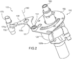
- the figures 1 and 2 are schematic representations of a first example and a second example of a locking module 100 according to the present invention.
- a locking module as shown in these figures, is generally implemented for the opening control ( figure 1 ) and / or closing ( figure 2 ) a power cut device and in particular a switch.
- an opening command and a closing command generally comprise the action of an arming system 110 provided with a means 120 for accumulating mechanical energy.
- the energy storage means 120 may in particular comprise a spring, and in particular a compression spring or a spiral spring (it is understood that a spiral spring within the meaning of the present invention is a flat spring with non-contiguous turns, for example wrapped around a tree).
- the accumulation means 120 can adopt one or the other of two said states, respectively, armed state and disarmed state, and is adapted to release a mechanical energy when it passes from the armed state to the disarmed state .
- the armed state results from arming (or arming phase) of the accumulation means 120.
- the locking module 100 comprises a lever 130 ( figure 1 , 2 , 3a, 3b , 4a, 4b ) in pivot connection around a first pivot shaft 140.
- the lever 130 comprises a first end 131 and a second end 132 (also called “hook”), the second end comprises a surface called the bearing surface 132a (see figure 1 ) which has a width, called the support width.
- the lever 130 comprises two lateral faces called, respectively, first face 130a and second face 130b connected by an outline 130c (the distance between the first 130a and the second face 130b defines the thickness E of the lever 130). It is understood without it being necessary to specify that the two lateral faces of the lever are perpendicular to the first pivot shaft 140.
- bearing face 132a is a small part of the contour 130c at the level of the second end 132.
- the accumulation means 120 exerts a thrust force on the first end 131 when it is in the armed state.
- the armament system can comprise a wheel 150 mechanically coupled to the accumulation means, and carrying a roller, called a stop roller 151, intended to apply the thrust force on the first end 131 ( figures 1 and 2 ).
- the locking module also includes a locking element 170 ( figures 1 , 2 , and 5 ) intended to adopt one or the other of two so-called positions, respectively, first position and second position.
- the first position corresponds to a position for which the bearing surface 132a is in abutment against a contact surface 170a ( figure 2 and 5 ) of the latch element 170 so as to oppose any rotation of the lever 130 due to the thrust force and maintain the accumulation means 120 in the armed state.
- the second position corresponds to a withdrawal of the contact surface 170a so as to allow the accumulation means 120 to pass from the armed state to the disarmed state.
- withdrawal of the contact surface means a sliding of said surface so that the latter disappears and no longer offers resistance to the thrust force exerted by the accumulation means 120 at the level of the second end 132 of lever 130.
- the lever 130 comprises at its second end a shoe 180 made of a metal strip ( figures 3c and 4c ).
- the pad is in particular arranged so as to be interposed between the contact surface 170a and the bearing surface 132a.
- the secondary surface 181 of width called the pad width, is in contact with the contact surface 170a (see figures 3c and 4c ), when said bearing surface is in abutment against the contact surface.
- the shoe is advantageously arranged symmetrically with respect to the lever 130.
- a metal strip is generally formed from a rolled metal sheet so that the latter has a surface condition, and in particular a roughness, compatible with a reduced coefficient of friction.
- the metal strip may include stainless steel.
- the secondary surface has a roughness of less than 1.6 ⁇ m Ra (“Ra” designating the arithmetic roughness), in particular a roughness of between 0.6 ⁇ m Ra and 1.6 ⁇ m Ra.
- the preparation of the secondary surface in particular to reduce its roughness, can be obtained by polishing techniques which are simpler to implement and less costly than the grinding methods used to grind. a portion of the surface of a machined part.
- the shoe width is greater than the support width, and in particular equal to at least twice the support width.
- the shoe 180 may include a retaining tab 182 which is engaged in a slot, called the retaining slot 133 formed in the lever so as to hold the shoe to said lever ( figures 3c and 4c ).
- the engagement of the retaining tab 182 in the retaining slot 133 ( figure 3a and 4a ) can be a strong commitment.
- the retaining slot 133 can be provided with a blocking element, in particular at least one lug, of the retaining tab 133.
- the lug can cooperate with a hole made in the retaining tab 182.
- this method of holding the pad 180 is not limited to the implementation of the holding tab, and the person skilled in the art may consider any other holding solution capable of being suitable.
- the shoe 180 can be maintained at the second end of the lever by gluing, by welding.
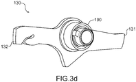
- the lever 130 comprises a hub 190 ( 3d figure and 4d ) molded in plastic material ensuring the pivot connection of said lever 130 with the first pivot shaft, advantageously the hub comprises a bore, crossed by the first pivot shaft, and extending over a length of at least three times the diameter of the pivot shaft.
- This arrangement in combination with a shoe width greater than the support width, makes it possible to consider a lever of reduced thickness, in particular of a thickness less than 6 mm, and more particularly between 2 mm and 6 mm .
- a lever in this range of thicknesses can be obtained by punching, cutting a metal sheet (for example stainless steel).
- This type of process is relatively simple to implement, and of a reduced cost compared to the machining techniques considered in the state of the art.
- the latch element 170 can include a half-moon ( figures 1 , 2 , and 5 ) in pivot connection around a second pivot shaft 171.
- the second pivot shaft 171 is advantageously essentially parallel to the first pivot shaft 140, the contact surface being defined by a section of the surface with cylindrical geometry of said half-moon .
- a half moon is a cylinder truncated along a plane parallel to the axis of revolution of said cylinder.
- the half-moon then comprises a remaining cylindrical surface, two edges of which are connected by a flat face.
- the remaining cylindrical section of the half moon includes the contact surface of the latch member.
- the half-moon is capable of pivoting around the second pivot shaft to adopt one or the other of the first position and the second position.
- the half-moon is in its first position so that, when said accumulation means exerts the thrust force, the bearing surface 132a comes to bear against the surface of half moon contact.
- the accumulation means accumulates mechanical energy, and is in the armed state.
- a tilting, or pivoting of the half-moon, from its first position to its second position breaks any resistance to the thrust force exerted by the accumulation means 120 so that the latter releases the mechanical energy accumulated during the arming phase, and ends up in the disarmed state.
- the figures 1 and 2 illustrate particular arrangements relating to the present invention.
- FIGS. 1 and 2 illustrate a locking module of an arming system provided, respectively, for the opening and for the closing of a current interruption device, and in particular a switch.
- the accumulation means 120 comprises a spiral spring, one end of which, called the central end 120a ( figure 6 ) is mechanically linked to a shaft, called armament shaft 160.
- the armament shaft 160 can advantageously be essentially parallel to the first pivot shaft 140.
- the mechanical connection between the armament shaft 160 and the central end 120a is advantageously ensured via a groove 160a formed in said armament shaft 160.
- peripheral end 120b ( figure 6 )
- peripheral end 120b ( figure 6 )
- a fixed element not shown in the figures for example, a fixed element linked to the frame of the device, figure 1 ).
- the wheel 150 is in a fixed connection relative to the armament shaft 160 ( figure 1 ).
- the spiral spring when it is in the armed state, exerts a force on the armament shaft 160, capable of causing the latter to rotate with the wheel 150.
- the wheel 150 then transmits the force of thrust, via the stop roller 151, at the first end 132 of the lever 130.
- peripheral end 120b can be in fixed connection with respect to the wheel 150 ( figure 2 ).
- the wheel 150 is then in pivot connection around the armament shaft 160 ( figure 2 ).
- the arming of the spiral spring is obtained by exerting a rotational force on the arming shaft 160.
- the stop roller 151 can be mounted in sliding connection on the wheel 150.
- the arming phase of the spiral spring then comprises two intermediate phases called, respectively, first phase and second phase.
- the first phase corresponds to a rotation, around the axis of rotation of the arming shaft 160, of the assembly formed by the spiral spring, the wheel 150 and the thrust roller 151.
- the stop roller 151 slides along the contour 130c of the lever 130 until it reaches the first end 131 of said lever 130.
- the second phase can begin.
- the bearing surface 132a is in abutment against the contact surface 170a (it is understood that the shoe is interposed between the bearing surface and the contact surface), so that the spring hairspring accumulates mechanical energy under the action of rotation exerted on the armament shaft.
- the invention also relates to a control module for the current cut-off device.
- the control module can comprise an arming system for opening a current cut-off device and / or an arming system for closing the current cut-off device.
- the arming system for opening and the arming system for closing are included in a common control module, the latter may include a common arming shaft.
- the invention also relates to an electrical switch device comprising a module according to the present invention.
Landscapes
- Engineering & Computer Science (AREA)
- General Engineering & Computer Science (AREA)
- Mechanical Engineering (AREA)
- Rotary Switch, Piano Key Switch, And Lever Switch (AREA)
- Lock And Its Accessories (AREA)
- Mechanisms For Operating Contacts (AREA)
- Driving Mechanisms And Operating Circuits Of Arc-Extinguishing High-Tension Switches (AREA)
- Braking Arrangements (AREA)
- Switch Cases, Indication, And Locking (AREA)
Applications Claiming Priority (1)
| Application Number | Priority Date | Filing Date | Title |
|---|---|---|---|
| FR1859165A FR3087044B1 (fr) | 2018-10-03 | 2018-10-03 | Module de verrouillage d'un systeme d'armement pour appareil electrique interrupteur |
Publications (2)
| Publication Number | Publication Date |
|---|---|
| EP3633703A1 true EP3633703A1 (de) | 2020-04-08 |
| EP3633703B1 EP3633703B1 (de) | 2021-08-25 |
Family
ID=65244100
Family Applications (1)
| Application Number | Title | Priority Date | Filing Date |
|---|---|---|---|
| EP19199499.5A Active EP3633703B1 (de) | 2018-10-03 | 2019-09-25 | Verriegelungsmodul eines aktivierungssystems für eine elektrische schaltvorrichtung |
Country Status (4)
| Country | Link |
|---|---|
| US (1) | US10811199B2 (de) |
| EP (1) | EP3633703B1 (de) |
| CN (1) | CN110993391B (de) |
| FR (1) | FR3087044B1 (de) |
Families Citing this family (1)
| Publication number | Priority date | Publication date | Assignee | Title |
|---|---|---|---|---|
| CN112923121B (zh) * | 2021-01-25 | 2023-05-16 | 重庆川仪自动化股份有限公司 | 旋转式阀门的拨盘组件、触发结构及阀门限位开关 |
Citations (2)
| Publication number | Priority date | Publication date | Assignee | Title |
|---|---|---|---|---|
| FR1586097A (de) * | 1964-07-08 | 1970-02-06 | ||
| FR2985600A1 (fr) * | 2012-01-06 | 2013-07-12 | Schneider Electric Ind Sas | Disjoncteur electrique de puissance a accumulateur d'energie et a dispositif de signalisation perfectionne de l'etat de fonctionnement |
Family Cites Families (9)
| Publication number | Priority date | Publication date | Assignee | Title |
|---|---|---|---|---|
| GB1251804A (de) | 1969-03-03 | 1971-11-03 | ||
| SE461557B (sv) * | 1989-04-28 | 1990-02-26 | Asea Brown Boveri | Kontaktanordning foer elkkopplare |
| FR2840726B1 (fr) * | 2002-06-06 | 2004-11-12 | Alstom | Commande mecanique a ressort pour disjoncteur haute ou moyenne tension, comprenant une roue dentee cooperant avec un pignon |
| MX2008001886A (es) * | 2005-08-10 | 2008-04-11 | Siemens Ag | Interruptor para circuito. |
| JP4833739B2 (ja) * | 2006-06-01 | 2011-12-07 | 株式会社日立製作所 | 遮断器 |
| KR100854384B1 (ko) * | 2007-03-08 | 2008-08-26 | 엘에스산전 주식회사 | 기중 차단기의 투입 스프링 자동 방세 장치 및 투입 스프링자동 방세 장치를 갖는 기중 차단기 |
| FR2914485B1 (fr) * | 2007-03-29 | 2009-04-24 | Schneider Electric Ind Sas | Dispositif de commande d'un appareil de protection electrique et appareil de protection electrique la comportant |
| FR2940511B1 (fr) * | 2008-12-18 | 2010-12-17 | Hager Electro Sas | Dispositif de declenchement mecanique pour appareil eletrique de coupure de ligne. |
| GB2495788A (en) * | 2012-01-14 | 2013-04-24 | Cosmos Wathingira Ngumi | Self-regenerating cleaning device |
-
2018
- 2018-10-03 FR FR1859165A patent/FR3087044B1/fr not_active Expired - Fee Related
-
2019
- 2019-09-23 CN CN201910897559.1A patent/CN110993391B/zh active Active
- 2019-09-25 EP EP19199499.5A patent/EP3633703B1/de active Active
- 2019-09-30 US US16/587,109 patent/US10811199B2/en active Active
Patent Citations (2)
| Publication number | Priority date | Publication date | Assignee | Title |
|---|---|---|---|---|
| FR1586097A (de) * | 1964-07-08 | 1970-02-06 | ||
| FR2985600A1 (fr) * | 2012-01-06 | 2013-07-12 | Schneider Electric Ind Sas | Disjoncteur electrique de puissance a accumulateur d'energie et a dispositif de signalisation perfectionne de l'etat de fonctionnement |
Also Published As
| Publication number | Publication date |
|---|---|
| CN110993391B (zh) | 2025-01-07 |
| CN110993391A (zh) | 2020-04-10 |
| FR3087044B1 (fr) | 2021-01-01 |
| US20200111623A1 (en) | 2020-04-09 |
| FR3087044A1 (fr) | 2020-04-10 |
| US10811199B2 (en) | 2020-10-20 |
| EP3633703B1 (de) | 2021-08-25 |
Similar Documents
| Publication | Publication Date | Title |
|---|---|---|
| FR2726872A1 (fr) | Embrayage a friction a compensation automatique d'usure | |
| EP2980658B1 (de) | Vorrichtung zum Zusammenbau und Regulieren einer Spirale | |
| EP3633703B1 (de) | Verriegelungsmodul eines aktivierungssystems für eine elektrische schaltvorrichtung | |
| FR2954722A3 (fr) | Ponceuse electrique comportant un mecanisme de blocage de plateau ponceur | |
| FR3056330A1 (fr) | Dispositif de coupure comportant un organe de rearmement | |
| EP3239550A1 (de) | Anordnung für eine kupplungsvorrichtung, insbesondere für kraftfahrzeug | |
| EP1734552B1 (de) | Betätigungseinrichtung eines elektrischen Schaltgeräts mit Drehsperre | |
| EP1889992B1 (de) | Einklappbarer Schlüssel | |
| FR3087418A1 (fr) | Systeme de fixation d'un siege | |
| EP3166123B1 (de) | Elektrischer schalter | |
| EP2330611A1 (de) | Selektiv-Leistungsschalter | |
| EP0254608B1 (de) | Einstellvorrichtung der relativen Stellung von zwei Teilen desselben Stückes, durch Verformung eines diese zwei Teile verbindenden Zwischenbereiches mittels einer konischen Schraube | |
| EP3488297B1 (de) | Regulierschlüssel | |
| EP3657522B1 (de) | Betätigungsmechanismus zum öffnen und schliessen einer stromunterbrechungsvorrichtung für einen elektrichen schalter | |
| EP2068332B1 (de) | Verriegelungsgerät für einen Steuerungsmechanismus eines elektrischen Getätes, und Steuerungsmechanismus mit solchem Verriegelungsgerät | |
| EP3182229B1 (de) | Chronographenmechanismus mit isoliertem schleppzeigermechanismus | |
| FR3050494A1 (fr) | Vis a faibles pertes de matiere pour systeme de freinage de vehicule | |
| CH716204B1 (fr) | Combiné disjoncteur et interrupteur sectionneur. | |
| FR2778789A1 (fr) | Appareil de coupure electrique pour installation electrique a basse tension alternative | |
| EP3662567B1 (de) | Rotierende elektrische maschine mit einem verkeilungselement | |
| WO2025228587A1 (fr) | Dispositif de coupure electrique | |
| EP1213730B1 (de) | Verbesserungen für elektrische Schaltvorrichtungen | |
| EP0407234B1 (de) | Scheibenbremse | |
| FR3014976A1 (fr) | Embrayage a friction | |
| FR3130002A1 (fr) | Système de freinage à désengagement sécurisé |
Legal Events
| Date | Code | Title | Description |
|---|---|---|---|
| PUAI | Public reference made under article 153(3) epc to a published international application that has entered the european phase |
Free format text: ORIGINAL CODE: 0009012 |
|
| STAA | Information on the status of an ep patent application or granted ep patent |
Free format text: STATUS: THE APPLICATION HAS BEEN PUBLISHED |
|
| AK | Designated contracting states |
Kind code of ref document: A1 Designated state(s): AL AT BE BG CH CY CZ DE DK EE ES FI FR GB GR HR HU IE IS IT LI LT LU LV MC MK MT NL NO PL PT RO RS SE SI SK SM TR |
|
| AX | Request for extension of the european patent |
Extension state: BA ME |
|
| STAA | Information on the status of an ep patent application or granted ep patent |
Free format text: STATUS: REQUEST FOR EXAMINATION WAS MADE |
|
| 17P | Request for examination filed |
Effective date: 20200910 |
|
| RBV | Designated contracting states (corrected) |
Designated state(s): AL AT BE BG CH CY CZ DE DK EE ES FI FR GB GR HR HU IE IS IT LI LT LU LV MC MK MT NL NO PL PT RO RS SE SI SK SM TR |
|
| RIC1 | Information provided on ipc code assigned before grant |
Ipc: H01H 3/30 20060101AFI20200922BHEP Ipc: F16H 33/02 20060101ALI20200922BHEP |
|
| GRAP | Despatch of communication of intention to grant a patent |
Free format text: ORIGINAL CODE: EPIDOSNIGR1 |
|
| STAA | Information on the status of an ep patent application or granted ep patent |
Free format text: STATUS: GRANT OF PATENT IS INTENDED |
|
| INTG | Intention to grant announced |
Effective date: 20201111 |
|
| GRAJ | Information related to disapproval of communication of intention to grant by the applicant or resumption of examination proceedings by the epo deleted |
Free format text: ORIGINAL CODE: EPIDOSDIGR1 |
|
| STAA | Information on the status of an ep patent application or granted ep patent |
Free format text: STATUS: REQUEST FOR EXAMINATION WAS MADE |
|
| GRAJ | Information related to disapproval of communication of intention to grant by the applicant or resumption of examination proceedings by the epo deleted |
Free format text: ORIGINAL CODE: EPIDOSDIGR1 |
|
| GRAS | Grant fee paid |
Free format text: ORIGINAL CODE: EPIDOSNIGR3 |
|
| STAA | Information on the status of an ep patent application or granted ep patent |
Free format text: STATUS: GRANT OF PATENT IS INTENDED |
|
| GRAP | Despatch of communication of intention to grant a patent |
Free format text: ORIGINAL CODE: EPIDOSNIGR1 |
|
| INTC | Intention to grant announced (deleted) | ||
| INTG | Intention to grant announced |
Effective date: 20210322 |
|
| GRAA | (expected) grant |
Free format text: ORIGINAL CODE: 0009210 |
|
| STAA | Information on the status of an ep patent application or granted ep patent |
Free format text: STATUS: THE PATENT HAS BEEN GRANTED |
|
| AK | Designated contracting states |
Kind code of ref document: B1 Designated state(s): AL AT BE BG CH CY CZ DE DK EE ES FI FR GB GR HR HU IE IS IT LI LT LU LV MC MK MT NL NO PL PT RO RS SE SI SK SM TR |
|
| REG | Reference to a national code |
Ref country code: CH Ref legal event code: EP |
|
| REG | Reference to a national code |
Ref country code: IE Ref legal event code: FG4D Free format text: LANGUAGE OF EP DOCUMENT: FRENCH Ref country code: AT Ref legal event code: REF Ref document number: 1424652 Country of ref document: AT Kind code of ref document: T Effective date: 20210915 |
|
| REG | Reference to a national code |
Ref country code: DE Ref legal event code: R096 Ref document number: 602019007131 Country of ref document: DE |
|
| REG | Reference to a national code |
Ref country code: LT Ref legal event code: MG9D |
|
| REG | Reference to a national code |
Ref country code: NL Ref legal event code: MP Effective date: 20210825 |
|
| REG | Reference to a national code |
Ref country code: AT Ref legal event code: MK05 Ref document number: 1424652 Country of ref document: AT Kind code of ref document: T Effective date: 20210825 |
|
| PG25 | Lapsed in a contracting state [announced via postgrant information from national office to epo] |
Ref country code: NO Free format text: LAPSE BECAUSE OF FAILURE TO SUBMIT A TRANSLATION OF THE DESCRIPTION OR TO PAY THE FEE WITHIN THE PRESCRIBED TIME-LIMIT Effective date: 20211125 Ref country code: PT Free format text: LAPSE BECAUSE OF FAILURE TO SUBMIT A TRANSLATION OF THE DESCRIPTION OR TO PAY THE FEE WITHIN THE PRESCRIBED TIME-LIMIT Effective date: 20211227 Ref country code: HR Free format text: LAPSE BECAUSE OF FAILURE TO SUBMIT A TRANSLATION OF THE DESCRIPTION OR TO PAY THE FEE WITHIN THE PRESCRIBED TIME-LIMIT Effective date: 20210825 Ref country code: AT Free format text: LAPSE BECAUSE OF FAILURE TO SUBMIT A TRANSLATION OF THE DESCRIPTION OR TO PAY THE FEE WITHIN THE PRESCRIBED TIME-LIMIT Effective date: 20210825 Ref country code: BG Free format text: LAPSE BECAUSE OF FAILURE TO SUBMIT A TRANSLATION OF THE DESCRIPTION OR TO PAY THE FEE WITHIN THE PRESCRIBED TIME-LIMIT Effective date: 20211125 Ref country code: LT Free format text: LAPSE BECAUSE OF FAILURE TO SUBMIT A TRANSLATION OF THE DESCRIPTION OR TO PAY THE FEE WITHIN THE PRESCRIBED TIME-LIMIT Effective date: 20210825 Ref country code: RS Free format text: LAPSE BECAUSE OF FAILURE TO SUBMIT A TRANSLATION OF THE DESCRIPTION OR TO PAY THE FEE WITHIN THE PRESCRIBED TIME-LIMIT Effective date: 20210825 Ref country code: SE Free format text: LAPSE BECAUSE OF FAILURE TO SUBMIT A TRANSLATION OF THE DESCRIPTION OR TO PAY THE FEE WITHIN THE PRESCRIBED TIME-LIMIT Effective date: 20210825 Ref country code: FI Free format text: LAPSE BECAUSE OF FAILURE TO SUBMIT A TRANSLATION OF THE DESCRIPTION OR TO PAY THE FEE WITHIN THE PRESCRIBED TIME-LIMIT Effective date: 20210825 Ref country code: ES Free format text: LAPSE BECAUSE OF FAILURE TO SUBMIT A TRANSLATION OF THE DESCRIPTION OR TO PAY THE FEE WITHIN THE PRESCRIBED TIME-LIMIT Effective date: 20210825 |
|
| PG25 | Lapsed in a contracting state [announced via postgrant information from national office to epo] |
Ref country code: PL Free format text: LAPSE BECAUSE OF FAILURE TO SUBMIT A TRANSLATION OF THE DESCRIPTION OR TO PAY THE FEE WITHIN THE PRESCRIBED TIME-LIMIT Effective date: 20210825 Ref country code: LV Free format text: LAPSE BECAUSE OF FAILURE TO SUBMIT A TRANSLATION OF THE DESCRIPTION OR TO PAY THE FEE WITHIN THE PRESCRIBED TIME-LIMIT Effective date: 20210825 Ref country code: GR Free format text: LAPSE BECAUSE OF FAILURE TO SUBMIT A TRANSLATION OF THE DESCRIPTION OR TO PAY THE FEE WITHIN THE PRESCRIBED TIME-LIMIT Effective date: 20211126 |
|
| PG25 | Lapsed in a contracting state [announced via postgrant information from national office to epo] |
Ref country code: NL Free format text: LAPSE BECAUSE OF FAILURE TO SUBMIT A TRANSLATION OF THE DESCRIPTION OR TO PAY THE FEE WITHIN THE PRESCRIBED TIME-LIMIT Effective date: 20210825 |
|
| PG25 | Lapsed in a contracting state [announced via postgrant information from national office to epo] |
Ref country code: DK Free format text: LAPSE BECAUSE OF FAILURE TO SUBMIT A TRANSLATION OF THE DESCRIPTION OR TO PAY THE FEE WITHIN THE PRESCRIBED TIME-LIMIT Effective date: 20210825 |
|
| REG | Reference to a national code |
Ref country code: BE Ref legal event code: MM Effective date: 20210930 |
|
| REG | Reference to a national code |
Ref country code: DE Ref legal event code: R097 Ref document number: 602019007131 Country of ref document: DE |
|
| PG25 | Lapsed in a contracting state [announced via postgrant information from national office to epo] |
Ref country code: SM Free format text: LAPSE BECAUSE OF FAILURE TO SUBMIT A TRANSLATION OF THE DESCRIPTION OR TO PAY THE FEE WITHIN THE PRESCRIBED TIME-LIMIT Effective date: 20210825 Ref country code: SK Free format text: LAPSE BECAUSE OF FAILURE TO SUBMIT A TRANSLATION OF THE DESCRIPTION OR TO PAY THE FEE WITHIN THE PRESCRIBED TIME-LIMIT Effective date: 20210825 Ref country code: RO Free format text: LAPSE BECAUSE OF FAILURE TO SUBMIT A TRANSLATION OF THE DESCRIPTION OR TO PAY THE FEE WITHIN THE PRESCRIBED TIME-LIMIT Effective date: 20210825 Ref country code: MC Free format text: LAPSE BECAUSE OF FAILURE TO SUBMIT A TRANSLATION OF THE DESCRIPTION OR TO PAY THE FEE WITHIN THE PRESCRIBED TIME-LIMIT Effective date: 20210825 Ref country code: EE Free format text: LAPSE BECAUSE OF FAILURE TO SUBMIT A TRANSLATION OF THE DESCRIPTION OR TO PAY THE FEE WITHIN THE PRESCRIBED TIME-LIMIT Effective date: 20210825 Ref country code: CZ Free format text: LAPSE BECAUSE OF FAILURE TO SUBMIT A TRANSLATION OF THE DESCRIPTION OR TO PAY THE FEE WITHIN THE PRESCRIBED TIME-LIMIT Effective date: 20210825 Ref country code: AL Free format text: LAPSE BECAUSE OF FAILURE TO SUBMIT A TRANSLATION OF THE DESCRIPTION OR TO PAY THE FEE WITHIN THE PRESCRIBED TIME-LIMIT Effective date: 20210825 |
|
| PLBE | No opposition filed within time limit |
Free format text: ORIGINAL CODE: 0009261 |
|
| STAA | Information on the status of an ep patent application or granted ep patent |
Free format text: STATUS: NO OPPOSITION FILED WITHIN TIME LIMIT |
|
| PG25 | Lapsed in a contracting state [announced via postgrant information from national office to epo] |
Ref country code: LU Free format text: LAPSE BECAUSE OF NON-PAYMENT OF DUE FEES Effective date: 20210925 Ref country code: IT Free format text: LAPSE BECAUSE OF FAILURE TO SUBMIT A TRANSLATION OF THE DESCRIPTION OR TO PAY THE FEE WITHIN THE PRESCRIBED TIME-LIMIT Effective date: 20210825 Ref country code: IE Free format text: LAPSE BECAUSE OF NON-PAYMENT OF DUE FEES Effective date: 20210925 Ref country code: BE Free format text: LAPSE BECAUSE OF NON-PAYMENT OF DUE FEES Effective date: 20210930 |
|
| 26N | No opposition filed |
Effective date: 20220527 |
|
| PG25 | Lapsed in a contracting state [announced via postgrant information from national office to epo] |
Ref country code: SI Free format text: LAPSE BECAUSE OF FAILURE TO SUBMIT A TRANSLATION OF THE DESCRIPTION OR TO PAY THE FEE WITHIN THE PRESCRIBED TIME-LIMIT Effective date: 20210825 |
|
| REG | Reference to a national code |
Ref country code: CH Ref legal event code: PL |
|
| PG25 | Lapsed in a contracting state [announced via postgrant information from national office to epo] |
Ref country code: CY Free format text: LAPSE BECAUSE OF FAILURE TO SUBMIT A TRANSLATION OF THE DESCRIPTION OR TO PAY THE FEE WITHIN THE PRESCRIBED TIME-LIMIT Effective date: 20210825 |
|
| PG25 | Lapsed in a contracting state [announced via postgrant information from national office to epo] |
Ref country code: LI Free format text: LAPSE BECAUSE OF NON-PAYMENT OF DUE FEES Effective date: 20220930 Ref country code: HU Free format text: LAPSE BECAUSE OF FAILURE TO SUBMIT A TRANSLATION OF THE DESCRIPTION OR TO PAY THE FEE WITHIN THE PRESCRIBED TIME-LIMIT; INVALID AB INITIO Effective date: 20190925 Ref country code: CH Free format text: LAPSE BECAUSE OF NON-PAYMENT OF DUE FEES Effective date: 20220930 |
|
| PG25 | Lapsed in a contracting state [announced via postgrant information from national office to epo] |
Ref country code: MK Free format text: LAPSE BECAUSE OF FAILURE TO SUBMIT A TRANSLATION OF THE DESCRIPTION OR TO PAY THE FEE WITHIN THE PRESCRIBED TIME-LIMIT Effective date: 20210825 |
|
| PG25 | Lapsed in a contracting state [announced via postgrant information from national office to epo] |
Ref country code: MT Free format text: LAPSE BECAUSE OF FAILURE TO SUBMIT A TRANSLATION OF THE DESCRIPTION OR TO PAY THE FEE WITHIN THE PRESCRIBED TIME-LIMIT Effective date: 20210825 |
|
| PGFP | Annual fee paid to national office [announced via postgrant information from national office to epo] |
Ref country code: DE Payment date: 20250926 Year of fee payment: 7 |
|
| PGFP | Annual fee paid to national office [announced via postgrant information from national office to epo] |
Ref country code: GB Payment date: 20250923 Year of fee payment: 7 |
|
| PGFP | Annual fee paid to national office [announced via postgrant information from national office to epo] |
Ref country code: FR Payment date: 20250925 Year of fee payment: 7 |
|
| PG25 | Lapsed in a contracting state [announced via postgrant information from national office to epo] |
Ref country code: TR Free format text: LAPSE BECAUSE OF FAILURE TO SUBMIT A TRANSLATION OF THE DESCRIPTION OR TO PAY THE FEE WITHIN THE PRESCRIBED TIME-LIMIT Effective date: 20210825 |