EP3633764B1 - Bloc-batterie - Google Patents
Bloc-batterie Download PDFInfo
- Publication number
- EP3633764B1 EP3633764B1 EP18810608.2A EP18810608A EP3633764B1 EP 3633764 B1 EP3633764 B1 EP 3633764B1 EP 18810608 A EP18810608 A EP 18810608A EP 3633764 B1 EP3633764 B1 EP 3633764B1
- Authority
- EP
- European Patent Office
- Prior art keywords
- batteries
- fuse links
- fuse
- battery
- battery pack
- Prior art date
- Legal status (The legal status is an assumption and is not a legal conclusion. Google has not performed a legal analysis and makes no representation as to the accuracy of the status listed.)
- Active
Links
Images







Classifications
-
- H—ELECTRICITY
- H01—ELECTRIC ELEMENTS
- H01M—PROCESSES OR MEANS, e.g. BATTERIES, FOR THE DIRECT CONVERSION OF CHEMICAL ENERGY INTO ELECTRICAL ENERGY
- H01M10/00—Secondary cells; Manufacture thereof
- H01M10/60—Heating or cooling; Temperature control
- H01M10/65—Means for temperature control structurally associated with the cells
- H01M10/655—Solid structures for heat exchange or heat conduction
- H01M10/6553—Terminals or leads
-
- H—ELECTRICITY
- H01—ELECTRIC ELEMENTS
- H01M—PROCESSES OR MEANS, e.g. BATTERIES, FOR THE DIRECT CONVERSION OF CHEMICAL ENERGY INTO ELECTRICAL ENERGY
- H01M50/00—Constructional details or processes of manufacture of the non-active parts of electrochemical cells other than fuel cells, e.g. hybrid cells
- H01M50/50—Current conducting connections for cells or batteries
- H01M50/572—Means for preventing undesired use or discharge
- H01M50/574—Devices or arrangements for the interruption of current
- H01M50/581—Devices or arrangements for the interruption of current in response to temperature
-
- H—ELECTRICITY
- H01—ELECTRIC ELEMENTS
- H01M—PROCESSES OR MEANS, e.g. BATTERIES, FOR THE DIRECT CONVERSION OF CHEMICAL ENERGY INTO ELECTRICAL ENERGY
- H01M10/00—Secondary cells; Manufacture thereof
- H01M10/42—Methods or arrangements for servicing or maintenance of secondary cells or secondary half-cells
- H01M10/44—Methods for charging or discharging
- H01M10/441—Methods for charging or discharging for several batteries or cells simultaneously or sequentially
-
- H—ELECTRICITY
- H01—ELECTRIC ELEMENTS
- H01M—PROCESSES OR MEANS, e.g. BATTERIES, FOR THE DIRECT CONVERSION OF CHEMICAL ENERGY INTO ELECTRICAL ENERGY
- H01M50/00—Constructional details or processes of manufacture of the non-active parts of electrochemical cells other than fuel cells, e.g. hybrid cells
- H01M50/20—Mountings; Secondary casings or frames; Racks, modules or packs; Suspension devices; Shock absorbers; Transport or carrying devices; Holders
- H01M50/204—Racks, modules or packs for multiple batteries or multiple cells
- H01M50/207—Racks, modules or packs for multiple batteries or multiple cells characterised by their shape
- H01M50/213—Racks, modules or packs for multiple batteries or multiple cells characterised by their shape adapted for cells having curved cross-section, e.g. round or elliptic
-
- H—ELECTRICITY
- H01—ELECTRIC ELEMENTS
- H01M—PROCESSES OR MEANS, e.g. BATTERIES, FOR THE DIRECT CONVERSION OF CHEMICAL ENERGY INTO ELECTRICAL ENERGY
- H01M50/00—Constructional details or processes of manufacture of the non-active parts of electrochemical cells other than fuel cells, e.g. hybrid cells
- H01M50/50—Current conducting connections for cells or batteries
- H01M50/502—Interconnectors for connecting terminals of adjacent batteries; Interconnectors for connecting cells outside a battery casing
- H01M50/505—Interconnectors for connecting terminals of adjacent batteries; Interconnectors for connecting cells outside a battery casing comprising a single busbar
-
- H—ELECTRICITY
- H01—ELECTRIC ELEMENTS
- H01M—PROCESSES OR MEANS, e.g. BATTERIES, FOR THE DIRECT CONVERSION OF CHEMICAL ENERGY INTO ELECTRICAL ENERGY
- H01M50/00—Constructional details or processes of manufacture of the non-active parts of electrochemical cells other than fuel cells, e.g. hybrid cells
- H01M50/50—Current conducting connections for cells or batteries
- H01M50/502—Interconnectors for connecting terminals of adjacent batteries; Interconnectors for connecting cells outside a battery casing
- H01M50/509—Interconnectors for connecting terminals of adjacent batteries; Interconnectors for connecting cells outside a battery casing characterised by the type of connection, e.g. mixed connections
-
- H—ELECTRICITY
- H01—ELECTRIC ELEMENTS
- H01M—PROCESSES OR MEANS, e.g. BATTERIES, FOR THE DIRECT CONVERSION OF CHEMICAL ENERGY INTO ELECTRICAL ENERGY
- H01M50/00—Constructional details or processes of manufacture of the non-active parts of electrochemical cells other than fuel cells, e.g. hybrid cells
- H01M50/50—Current conducting connections for cells or batteries
- H01M50/502—Interconnectors for connecting terminals of adjacent batteries; Interconnectors for connecting cells outside a battery casing
- H01M50/509—Interconnectors for connecting terminals of adjacent batteries; Interconnectors for connecting cells outside a battery casing characterised by the type of connection, e.g. mixed connections
- H01M50/51—Connection only in series
-
- H—ELECTRICITY
- H01—ELECTRIC ELEMENTS
- H01M—PROCESSES OR MEANS, e.g. BATTERIES, FOR THE DIRECT CONVERSION OF CHEMICAL ENERGY INTO ELECTRICAL ENERGY
- H01M50/00—Constructional details or processes of manufacture of the non-active parts of electrochemical cells other than fuel cells, e.g. hybrid cells
- H01M50/50—Current conducting connections for cells or batteries
- H01M50/502—Interconnectors for connecting terminals of adjacent batteries; Interconnectors for connecting cells outside a battery casing
- H01M50/509—Interconnectors for connecting terminals of adjacent batteries; Interconnectors for connecting cells outside a battery casing characterised by the type of connection, e.g. mixed connections
- H01M50/512—Connection only in parallel
-
- H—ELECTRICITY
- H01—ELECTRIC ELEMENTS
- H01M—PROCESSES OR MEANS, e.g. BATTERIES, FOR THE DIRECT CONVERSION OF CHEMICAL ENERGY INTO ELECTRICAL ENERGY
- H01M50/00—Constructional details or processes of manufacture of the non-active parts of electrochemical cells other than fuel cells, e.g. hybrid cells
- H01M50/50—Current conducting connections for cells or batteries
- H01M50/502—Interconnectors for connecting terminals of adjacent batteries; Interconnectors for connecting cells outside a battery casing
- H01M50/514—Methods for interconnecting adjacent batteries or cells
- H01M50/516—Methods for interconnecting adjacent batteries or cells by welding, soldering or brazing
-
- H—ELECTRICITY
- H01—ELECTRIC ELEMENTS
- H01M—PROCESSES OR MEANS, e.g. BATTERIES, FOR THE DIRECT CONVERSION OF CHEMICAL ENERGY INTO ELECTRICAL ENERGY
- H01M50/00—Constructional details or processes of manufacture of the non-active parts of electrochemical cells other than fuel cells, e.g. hybrid cells
- H01M50/50—Current conducting connections for cells or batteries
- H01M50/502—Interconnectors for connecting terminals of adjacent batteries; Interconnectors for connecting cells outside a battery casing
- H01M50/521—Interconnectors for connecting terminals of adjacent batteries; Interconnectors for connecting cells outside a battery casing characterised by the material
- H01M50/522—Inorganic material
-
- H—ELECTRICITY
- H01—ELECTRIC ELEMENTS
- H01M—PROCESSES OR MEANS, e.g. BATTERIES, FOR THE DIRECT CONVERSION OF CHEMICAL ENERGY INTO ELECTRICAL ENERGY
- H01M2200/00—Safety devices for primary or secondary batteries
- H01M2200/10—Temperature sensitive devices
- H01M2200/103—Fuse
-
- H—ELECTRICITY
- H01—ELECTRIC ELEMENTS
- H01M—PROCESSES OR MEANS, e.g. BATTERIES, FOR THE DIRECT CONVERSION OF CHEMICAL ENERGY INTO ELECTRICAL ENERGY
- H01M50/00—Constructional details or processes of manufacture of the non-active parts of electrochemical cells other than fuel cells, e.g. hybrid cells
- H01M50/20—Mountings; Secondary casings or frames; Racks, modules or packs; Suspension devices; Shock absorbers; Transport or carrying devices; Holders
- H01M50/218—Mountings; Secondary casings or frames; Racks, modules or packs; Suspension devices; Shock absorbers; Transport or carrying devices; Holders characterised by the material
- H01M50/22—Mountings; Secondary casings or frames; Racks, modules or packs; Suspension devices; Shock absorbers; Transport or carrying devices; Holders characterised by the material of the casings or racks
- H01M50/227—Organic material
-
- H—ELECTRICITY
- H01—ELECTRIC ELEMENTS
- H01M—PROCESSES OR MEANS, e.g. BATTERIES, FOR THE DIRECT CONVERSION OF CHEMICAL ENERGY INTO ELECTRICAL ENERGY
- H01M50/00—Constructional details or processes of manufacture of the non-active parts of electrochemical cells other than fuel cells, e.g. hybrid cells
- H01M50/20—Mountings; Secondary casings or frames; Racks, modules or packs; Suspension devices; Shock absorbers; Transport or carrying devices; Holders
- H01M50/289—Mountings; Secondary casings or frames; Racks, modules or packs; Suspension devices; Shock absorbers; Transport or carrying devices; Holders characterised by spacing elements or positioning means within frames, racks or packs
-
- H—ELECTRICITY
- H01—ELECTRIC ELEMENTS
- H01M—PROCESSES OR MEANS, e.g. BATTERIES, FOR THE DIRECT CONVERSION OF CHEMICAL ENERGY INTO ELECTRICAL ENERGY
- H01M50/00—Constructional details or processes of manufacture of the non-active parts of electrochemical cells other than fuel cells, e.g. hybrid cells
- H01M50/50—Current conducting connections for cells or batteries
- H01M50/543—Terminals
-
- H—ELECTRICITY
- H01—ELECTRIC ELEMENTS
- H01M—PROCESSES OR MEANS, e.g. BATTERIES, FOR THE DIRECT CONVERSION OF CHEMICAL ENERGY INTO ELECTRICAL ENERGY
- H01M50/00—Constructional details or processes of manufacture of the non-active parts of electrochemical cells other than fuel cells, e.g. hybrid cells
- H01M50/50—Current conducting connections for cells or batteries
- H01M50/543—Terminals
- H01M50/547—Terminals characterised by the disposition of the terminals on the cells
- H01M50/548—Terminals characterised by the disposition of the terminals on the cells on opposite sides of the cell
-
- Y—GENERAL TAGGING OF NEW TECHNOLOGICAL DEVELOPMENTS; GENERAL TAGGING OF CROSS-SECTIONAL TECHNOLOGIES SPANNING OVER SEVERAL SECTIONS OF THE IPC; TECHNICAL SUBJECTS COVERED BY FORMER USPC CROSS-REFERENCE ART COLLECTIONS [XRACs] AND DIGESTS
- Y02—TECHNOLOGIES OR APPLICATIONS FOR MITIGATION OR ADAPTATION AGAINST CLIMATE CHANGE
- Y02E—REDUCTION OF GREENHOUSE GAS [GHG] EMISSIONS, RELATED TO ENERGY GENERATION, TRANSMISSION OR DISTRIBUTION
- Y02E60/00—Enabling technologies; Technologies with a potential or indirect contribution to GHG emissions mitigation
- Y02E60/10—Energy storage using batteries
Definitions
- the present invention relates to a battery pack that includes a battery holder that arranges a plurality of batteries at predetermined positions, and bus bars that connect the plurality of batteries with each other in series or in parallel. More specifically, the present invention relates to a battery pack that includes the bus bars that include fuse links melted by an overcurrent of the batteries.
- a battery pack that includes bus bars that connect a plurality of batteries with each other in series or in parallel includes fuse links at the bus bars, and thus does not allow an overcurrent of the batteries (see PTLs 1 and 2).
- Each of the bus bars is a metal sheet that connects the batteries with each other in series or in parallel. Each of the bus bars is made by cutting one metal sheet.
- a base that connects the batteries with each other in series or in parallel, and fixed terminals connected with electrode terminals of the batteries are connected with each other by fuse links.
- the fixed terminals are connected with the base through the fuse links. Therefore, the fuse links are designed such that the fuse links melt when an electric current of the batteries, that is, an electric current that flows through the fixed terminals, exceeds an assigned electric current.
- the assigned electric current that melts the fuse links is adjusted by electrical resistance of the fuse links. Therefore, if the fuse links are metal sheets that are very conductive, an assigned electric current is adjusted by narrowing and lengthening the fuse links.
- Electrical resistance of a metal wire is generally in proportion to a length of the metal wire, and is in inverse proportion to an area of a cross section of the metal wire. Therefore, a value of electrical resistance of a fuse link made by cutting a metal sheet is increased by narrowing a width of the fuse link and lengthening a length of the fuse link. Therefore, the fuse link is narrowed and lengthened to increase the electrical resistance. Consequently, when an assigned overcurrent flows through the fuse link, the fuse link generates heat and melts.
- US2016315304A1 discloses a fusible battery interconnect that is integral to a bus bar, thereby allowing rapid, cost effective, and highly reliable connections to be made between the bus bar and the batteries within a battery pack.
- EP2608243A1 discloses a fuse board and a battery block equipped with the fuse board.
- the fuse board includes a metal plate, a connection portion connected to a cell, a fuse portion connecting the metal plate to the connection portion, and an insulating resin film bonded to the fuse portion, wherein a wiring pattern of the fuse portion has a bent portion, and the insulating resin film has a rectangular sheet-like shape that covers one surface of the fuse portion.
- JP2002075329A discloses a mounting method of a PTC (Positive Temperature Coefficient) element and a battery pack using it. The PTC element is mounted on a thermally insulating paper
- a fuse link is heated by Joule heat due to an overcurrent, and melts.
- Joule heat is determined by a product of a square of an electric current and electrical resistance. Therefore, an assigned electric current that melts a fuse link is determined by adjusting electrical resistance of the fuse link.
- a fuse link is designed such that the fuse link surely melts when an assigned electric current flows through the fuse link.
- a circuit is rapidly shut off when a battery is in an abnormal state. Therefore, it is important to melt a fuse link as rapidly as possible, and surely stop an overcurrent.
- a bus bar is made of a metal sheet that is very conductive. In other words, electricity easily flows through the metal sheet.
- a width of a fuse link is narrowed, and a length of the fuse link is lengthened to increase its electrical resistance.
- a metal sheet that has a narrow width and is long has a physically low strength. Therefore, the metal sheet is likely to be broken by impacts, such as vibration or a fall.
- electrical resistance of a fuse link of a bus bar needs to be adjusted to allow the fuse link to rapidly and surely melt when an assigned electric current flows through the fuse link.
- a width of a metal sheet needs to be narrowed, and a length of the metal sheet needs to be lengthened.
- a structure that increases strength of a fuse link is needed for a bus bar included in a battery pack and connected with batteries. The strength of the fuse link are increased by widening a width of a metal sheet or shortening a length of the metal sheet, to increase the impact resistance of the fuse link.
- high electrical resistance and high strength are inconsistent. Therefore, it has been thought that the high electrical resistance and the high strength are not satisfied simultaneously.
- the present invention is developed to solve the above problems. It is an object of the present invention to provide a battery pack that effectively does not allow fuse links to be broken by vibration or an impact, and allows the fuse links to rapidly and surely melt when an overcurrent flows through the fuse links, and thus protects batteries.
- a battery pack includes a plurality of batteries 1 that are chargeable and dischargeable, a battery holder 2 that arranges the batteries 1 at predetermined positions, and a bus bar 3 that is a metal sheet fixed to electrode terminals 1x, 1y of batteries 1.
- the bus bar 3 includes a plurality of fixed terminals 3A connected with the electrode terminals 1x, 1y of batteries 1, the base 3B that connects the plurality of batteries 1 with each other through the plurality of fixed terminals 3A in series and/or in parallel, and fuse links 3C that include ends that are connected with the fixed terminals 3A, respectively, and roots that are connected with the base 3B.
- the battery pack further includes a heat insulating member 8 that tightly covers surfaces of the fuse links 3C, and surfaces of the fixed terminals 3A connected with the fuse links 3C, respectively.
- the above battery pack effectively does not allow the fuse links to be broken by vibration or an impact, and allows the fuse links to rapidly and surely melt when an overcurrent flows through the fuse links, and thus protects the batteries.
- the heat insulating member tightly covers surfaces of the fuse links of the bus bar, and surfaces of the fixed terminals connected with the fuse links.
- the heat insulating member tightly covers surfaces of the fuse links and surfaces of the fixed terminals. Therefore, both the fuse links and the fixed terminals are insulated from outside. Therefore, heat is allowed to accumulate in the fuse links when the batteries are in an abnormal state. Therefore, the fuse links rapidly melt. For example, if thermal runaway occurs in a battery due to internal short circuit, a temperature of the battery rapidly increases.
- Thermal energy is released from the battery to outside.
- the heat insulating member tightly covers surfaces of the fuse links and surfaces of the fixed terminals, release of heat from the surfaces to outside is reduced. Therefore, heat accumulates in the fixed terminals and the fuse links. Therefore, heat generated in the battery is effectively transferred to the fuse links through the fixed terminals. Consequently, the fuse links are rapidly heated.
- a large short-circuit electric current flows through the battery. Therefore, the large short-circuit electric current generates Joule heat at the fuse links.
- the heat insulating member tightly covers surfaces of the fuse links, heat accumulates in the fuse links. Therefore, the fuse links are effectively heated by the Joule heat. Therefore, temperatures of the fuse links rapidly increase to a melting point. Consequently, the fuse links rapidly melt, and rapidly stop a large short-circuit electric current that flows through the battery.
- the heat insulating member covers surfaces of the fixed terminals. While the fixed terminals reduce release of heat energy that has been generated in a battery to outside, heat is efficiently transferred to the fuse links from the electrode terminals, and thus the fuse links are heated. Heat transfer from the fixed terminals to the fuse links efficiently heats the fuse links. In addition, the heat insulating member covers surfaces of the fuse links. Therefore, release of Joule heat that is generated by an overcurrent that flows through the fuse links is reduced. Therefore, the battery pack rapidly increases a temperature of the fuse links. That is, when a battery is in an abnormal state, heat that is generated in the battery is efficiently transferred to the fuse links through the fixed terminals, and thus the fuse links are heated.
- the heat insulating member tightly covers surfaces of the fuse links and surfaces of the fixed terminals. Therefore, temperatures of the fuse links rapidly and efficiently increase to a melting point. Therefore, even if an area of a transverse cross-section of the fuse links is designed to be increased, for example, even if a width of the fuse links that are metal sheets is increased or even if a length of the fuse links are is designed to be shortened, temperatures of the fuse links surely increase to a melting point when a battery is in an abnormal state, and the fuse links melt.
- Such a battery pack that allows a width of the fuse links to be widened, or allows a length of the fuse links to be shortened increases strength of the fuse links. Therefore, the battery pack effectively does not allow the fuse links to be broken by impacts, such as vibration and a fall.
- the heat insulating member tightly covers surfaces of the fuse links and surfaces of the fixed terminals. Therefore, the battery pack effectively does not allow the fuse links and the fixed terminals to move relative to the base of the bus bar when the battery pack receives vibration or an impact. The reason is that the heat insulating member that covers surfaces of the fuse links and surfaces of the fixed terminals does not allow movement of the fuse links and movement of the fixed terminals. Such a battery pack that does not allow the fuse links and the fixed terminals to move relative to the base improves impact resistance. In various applications, the battery pack does not lose a fuse function, and is safely used.
- the heat insulating member 8 may be made of a potting resin.
- the heat insulating member is made of the potting resin. Therefore, the heat insulating member that tightly covers surfaces of the fuse links and surfaces of the fixed terminals is easily made by filling the potting resin on the surfaces of the fuse links and the surfaces of the fixed terminals. Further, manufacturing cost is reduced by minimizing an amount of potting resin used to cover the surfaces of the fuse links and the surfaces of the fixed terminals.
- the heat insulating member 8 includes a cover 8A into which resin is molded, and the cover 8A is tightly fixed to surfaces of the fuse links 3C and surfaces of the fixed terminals 3A connected with the fuse links 3C.
- the cover into which resin is molded is fixed to a surface of the bus bar, and thus tightly covers the fuse links and the fixed terminals. Therefore, the surface of the bus bar may be covered with a cover that has been preliminarily manufactured in another step. Therefore, a manufacturing time is reduced. Further, due to the structure, the fuse links and the fixed terminals are always similarly covered by manufacturing covers that each have a same shape and a same thickness. Therefore, a time it takes for the fuse links to melt is constant. Therefore, the fuse links stably melt when an assigned electric current flows through the fuse links.
- the bus bar 3 includes the plurality of fuse links 3C, and the heat insulating member 8 is integrally molded to tightly cover surfaces of all the fuse links 3C of the bus bar 3.
- the bus bar includes the plurality of fuse links, and the heat insulating member is integrally molded to tightly cover surfaces of all the fuse links. Therefore, the heat insulating member uniformly covers the fuse links, and a time for which the heat insulating member is molded is reduced. Since the heat insulating member uniformly covers surfaces of all the fuse links of the bus bar, the fuse links are stably heated, and the fuse links surely melt when an assigned electric current flows through the fuse links.
- the heat insulating member 8 is on a whole surface of the bus bar 3.
- the heat insulating member is on a whole surface of the bus bar. Therefore, a manufacturing time is reduced, and the heat insulating member covers the plurality of fuse links and the fixed terminals of the bus bar. Especially if the heat insulating member is made of a potting resin, surfaces of the fuse links and surfaces of the fixed terminals are uniformly covered by applying the potting resin on a whole surface of the bus bar. Further, a thickness of the heat insulating member becomes uniform. If the heat insulating member is the cover, an outer shape of the cover and an outer shape of the bus bar are equalized. Consequently, a whole surface of the bus bar is easily covered with the cover, and the cover is disposed at a predetermined position.
- the battery holder 2 puts the plurality of batteries 1 parallel to each other, and arranges, on same planes, the electrode terminals 1x, 1y at both ends of the batteries 1, and the bus bar 3 connects the electrode terminals 1x, 1y of the batteries 1 with each other at each of both surfaces of the battery holder 2.
- the battery holder 2 includes a positioning hollow 2D on each of both the surfaces on which the electrode terminals 1x, 1y of the batteries 1 are arranged, the bus bar 3 is disposed in the positioning hollow 2D, and the heat insulating member 8 is disposed in the positioning hollow 2D.
- the bus bar is disposed in the positioning hollow on each of both the surfaces of the battery holder, and the heat insulating member is disposed in the positioning hollow. Therefore, an inner wall of the positioning hollow functions as a boundary wall, and the heat insulating member is precisely disposed relative to a surface of the bus bar. If the potting resin is filled to form the heat insulating member, for example, the inner wall of the positioning hollow of the battery holder also functions as a peripheral wall of an area where the potting resin is filled. Consequently, the potting resin does not spread outside the positioning hollow, and the potting resin is efficiently filled. If the heat insulating member is the cover, the inner wall of the positioning hollow of the battery holder also functions as a positioning wall used to position a peripheral edge of the cover. Consequently, the cover is easily disposed at a precise position.
- the base 2B includes fuse-link connecting portions 3Ba that are connected with the roots of the fuse links 3C, respectively, and the fuse-link connecting portions 3Ba include first fitting portions 3I, respectively
- battery holder 2 includes second fitting portions 2C, and the second fitting portions 2C are connected with the first fitting portions 3I, respectively, and thus the second fitting portions 2C are connected with the fuse-link connecting portions 3Ba, respectively, the second fitting portions 2C are connected with the first fitting portions 3I, respectively, and thus the fuse-link connecting portions 3Ba are connected with the battery holder 2, and the heat insulating member 8 fixes connections between the first fitting portions 3I and the second fitting portions 2C.
- the fuse-link connecting portions are connected with roots of the fuse links, respectively.
- the fuse-link connecting portions include the first fitting portions, respectively.
- the second fitting portions of the battery holder are connected with the first fitting portions, respectively. Consequently, the fuse-link connecting portions are connected with the battery holder. Consequently, the fuse links are connected with the battery holder in such a manner that the fuse links do not move relative to the battery holder.
- the heat insulating member fixes connections between the first fitting portions and the second fitting portions. Therefore, the heat insulating member fixes both the battery holder and the fuse-link connecting portions at predetermined positions. Therefore, the fuse links and the batteries surely do not move relative to each other. Therefore, even if the above battery pack receives an impact, such as a fall, the fuse links and the batteries do not move relative to each other. Consequently, the fuse links are not damaged.
- the base 3B of the bus bar 3 includes a positioning hole 3K between the fixed terminals 3A that are adjacent to each other.
- the battery holder 2 includes a positioning rib 2F that is guided by the positioning hole 3K and is connected with the bus bar 3.
- the positioning rib 2F is connected with the positioning hole 3K, and thus the bus bar 3 is connected with the battery holder 2.
- the heat insulating member 8 fixes a connection between the positioning hole 3K and the positioning rib 2F.
- the positioning rib of the battery holder is connected with the positioning hole of the base of the bus bar. Consequently, the bus bar is connected with the battery holder. Further, the heat insulating member fixes a connection between the positioning hole and the positioning rib. Therefore, the heat insulating member stably fixes the bus bar at a predetermined position on the battery holder.
- one component may constitute a plurality of elements of the elements, or one component may serve as a plurality of elements of the elements.
- a function of one component may be shared by a plurality of components.
- the battery pack according to an aspect of the present invention is mainly used as a power source for motor.
- the battery pack is used as a power source for electric motor equipment operated by a motor, such as electric tools, electric-assist bicycles, electric motorcycles, electric wheelchairs, electric tricycles, and electric carts.
- electric motor equipment operated by a motor
- the present invention does not limit applications of the battery pack.
- the battery pack may be used as a power source for various electric equipment except electric motor equipment, such as cleaners, transceivers, lights, digital cameras, and video cameras that are used indoors or outdoors.
- FIGS. 1 to 6 illustrate a battery pack according to an exemplary embodiment of the present invention.
- FIG. 1 illustrates a horizontal cross-sectional view of the battery pack.
- FIG. 2 illustrates a vertical cross-sectional view of the battery pack.
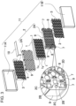
- FIG. 3 illustrates an exploded perspective view of the battery pack.
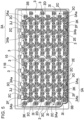
- FIG. 4 illustrates a front view that illustrates an internal configuration of the battery pack.
- FIG. 5 illustrates a rear view that illustrates the internal configuration of the battery pack.
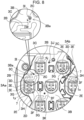
- FIG. 6 illustrates an enlarged perspective view that illustrates the internal configuration of the battery pack.
- 1 to 6 includes a plurality of batteries 1 that are chargeable and dischargeable, battery holder 2 that arranges the plurality of batteries 1 at predetermined positions, and bus bars 3 that are metal sheets fixed to electrode terminals 1x, 1y of batteries 1.
- Battery holder 2 puts the plurality of batteries 1 parallel to each other, arranges both ends of the plurality of batteries 1 on same planes, and arranges the plurality of batteries 1 at predetermined positions.
- the plurality of batteries 1 which battery holder 2 arranges at predetermined positions are connected with each other in series and in parallel by bus bars 3.
- Each of bus bars 3 includes a plurality of fixed terminals 3A connected with the electrode terminals of batteries 1, base 3B that connects the plurality of batteries 1 with each other through the plurality of fixed terminals 3A in series and/or in parallel, and fuse links 3C that include ends that connect with fixed terminals 3A, respectively, and roots that connect with base 3B.
- the battery pack also includes heat insulating member 8 that tightly covers surfaces of fuse links 3C, and surfaces of fixed terminals 3A connected with fuse links 3C, respectively, at a close contact state. In FIGS. 2 , 4 , and 5 , heat insulating member 8 is not illustrated to allow a configuration of the battery pack to be easily seen. Further, battery holder 2 that arranges the plurality of batteries 1 at predetermined positions are disposed in external case 11. Consequently, the battery pack is assembled.
- the battery pack in the drawings includes batteries 1 that are cylindrical batteries.
- Each of the cylindrical batteries includes an exterior can that is cylindrical, an electrode assembly disposed within the exterior can, electrolyte filled within the exterior can, and a sealing plate that seals an opening of the exterior can.
- a bottom surface of the exterior can, and a projection electrode at a center of the sealing plate are both end surfaces of the cylindrical battery.
- the bottom surface of the exterior can and the projection electrode at a center of the sealing plate are positive and negative electrode terminals 1x, 1y.
- the cylindrical batteries that each include positive and negative electrode terminals 1x, 1y at both the end surfaces of each of the cylindrical batteries are arranged parallel to each other by battery holder 2.
- Battery holder 2 exposes electrode terminals 1x, 1y at both ends of the cylindrical batteries.
- Electrode terminals 1x, 1y are connected with each other in series and in parallel by bus bars 3.
- the batteries are non-aqueous-electrolyte secondary batteries, such as lithium-ion batteries. However, the present invention does not limit batteries to lithium-ion batteries. All secondary batteries that are currently used or will now be developed, such as other non-aqueous-electrolyte secondary batteries or nickel metal hydride batteries may be used.
- Battery holder 2 is made of resin, such as a thermoplastic resin that is an insulating material. Battery holder 2 is molded into a predetermined shape. Preferably, battery holder 2 may be made of a flame-resistant resin. Polycarbonate (PC) or polypropylene (PP) can be used as such a resin.
- PC polycarbonate
- PP polypropylene
- the plurality of batteries 1 are inserted into battery accommodating portions 4 of battery holder 2.
- Battery holder 2 arranges the plurality of batteries 1 at predetermined positions, and thus the plurality of batteries 1 are parallel to each other.
- electrode terminals 1x, 1y at both end surfaces of batteries 1 are arranged on same planes. Consequently, electrode terminals 1x, 1y are exposed from both surfaces of battery holder 2.
- Partition wall 5 partitions battery holder 2 into battery accommodating portions 4. Partition wall 5 is in contact with and is thermally connected with outer curved surfaces of batteries 1 in a thermal-coupling state. Heat generated in batteries 1 is transferred to partition wall 5 thermally connected with batteries 1. Consequently, partition wall 5 absorbs heat generated in batteries 1.
- Partition wall 5 that partitions battery holder 2 into battery accommodating portions 4 is between batteries 1 that are adjacent to each other. Surfaces of partition wall 5 are in contact with surfaces of batteries 1. Partition wall 5 is thermally connected with batteries 1. Partition wall 5 is in contact with surfaces of batteries 1, and thus arranges batteries 1 at predetermined positions. Batteries 1 are inserted into battery accommodating portions 4 into which partition wall 5 partitions battery holder 2, and thus are arranged at predetermined positions. Accordingly, inner surfaces of battery accommodating portions 4 each have an inner shape that corresponds to an outer curved surface of battery 1. Battery accommodating portions 4 of battery holder 2 in the drawings each have an inner shape that is cylindrical since the cylindrical batteries are inserted into battery accommodating portions 4, and thus are arranged at predetermined positions.
- An inner diameter of battery accommodating portions 4 that are cylindrical is slightly larger than an outer diameter of the cylindrical batteries.
- Battery accommodating portions 4 are thermally connected with the cylindrical batteries.
- Battery accommodating portions 4 arrange cylindrical batteries at predetermined positions.
- a surface of partition wall 5 between batteries 1 has a shape that corresponds to a surface of the cylindrical battery since partition wall 5 partitions battery holder 2 into battery accommodating portions 4.
- the plurality of battery accommodating portions 4 are parallel to each other.
- Battery holder 2 includes partition wall 5 between the batteries, and peripheral wall 9 that surrounds battery holder 2.
- Partition wall 5 and peripheral wall 9 are integrally molded.
- Battery holder 2 includes battery accommodating portions 4 arranged between peripheral wall 9 and partition wall 5 at a peripheral portion of the battery holder 2, and battery accommodating portions 4 arranged between partition walls 5 inside battery holder 2.
- Partition wall 5 and peripheral wall 9 have battery contact surfaces that each have a shape that corresponds to a surface of battery 1.
- Partition wall 5 and peripheral wall 9 are thermally connected with batteries 1, and arrange batteries 1 at predetermined positions.
- Battery holder 2 arranges batteries 1 in such a manner that a space is used efficiently. Therefore, whole battery holder 2 is compact. Resin at valley portions is reduced. Consequently, an amount of used resin is reduced, and thus manufacturing cost is reduced, and a weight is reduced.
- battery holder 2 may vertically and laterally arrange batteries, and batteries may be arranged at intersections of a grid.
- Battery holder 2 in FIGS. 2 and 3 arranges 112 batteries 1 in eight rows and fourteen columns.
- Battery holder 2 includes partition wall 5 between batteries 1 that are arranged in a plurality of rows and a plurality of columns. In other words, partition wall 5 forms battery accommodating portions 4. Batteries 1 are arranged between partition walls 5. Heat of batteries 1 is transferred to partition wall 5.
- Battery holder 2 illustrated in FIGS. 1 and 3 is divided into halves, and includes a pair of holder units 2A. Holder units 2A are open at electrode windows 7. Electrode windows 7 are at both ends of battery accommodating portions 4 that hold batteries 1 that have been inserted into battery accommodating portions 4. Electrode windows 7 expose electrode terminals 1x, 1y at both ends of batteries 1. Bus bars 3 are connected with electrode terminals 1x, 1y of batteries 1 which electrode windows 7 expose. In battery holder 2 in FIG. 2 , electrode windows 7 that expose electrode terminals 1y of batteries 1 each have a square shape. Electrode windows 7 that expose other electrode terminals 1x of batteries 1 each have a circular shape. Electrode windows 7 are smaller than an outer shape of batteries 1, and thus batteries 1 do not pass through electrode windows 7, and batteries 1 are arranged in battery accommodating portions 4.
- Battery holder 2 illustrated in FIGS. 3 and 6 is molded, and thus includes positioning hollows 2D at both surfaces of battery holder 2. Each of positioning hollows 2D arranges bus bars 3 at predetermined positions. Battery holder 2 in FIGS. 3 and 6 includes the plurality of positioning hollows 2D that arrange the plurality of bus bars 3 at predetermined positions. Positioning hollows 2D each have a shape that corresponds to a periphery of bus bars 3. Therefore, bus bars 3 are inserted into positioning hollows 2D while bus bars 3 are positioned. Battery holder 2 in FIGS. 3 and 6 includes boundary walls 2E at both surfaces of battery holder 2. Boundary walls 2E correspond to a periphery of bus bars 3. Areas within boundary walls 2E are positioning hollows 2D.
- Bottom surfaces of positioning hollows 2D of battery holder 2 are lower than an end surface of battery holder 2, more specifically, an end surface of boundary walls 2E. Bottom surfaces of positioning hollows 2D are open at the plurality of electrode windows 7.
- the plurality of bus bars 3 are arranged on a same plane at the bottom surfaces. Bus bars 3 are arranged in positioning hollows 2D formed at both surfaces of battery holder 2, and bus bars 3 are connected with batteries 1. Then heat insulating member 8 is disposed in positioning hollows 2D.
- a length of battery accommodating portions 4 formed by the pair of holder units 2A of battery holder 2, that is, a thickness of one of holder units 2A, is substantially same as a half of a total length of batteries 1.
- Holder units 2A that are in connect with each other form battery accommodating portions 4.
- Batteries 1 are inserted into battery accommodating portions 4. Consequently, battery accommodating portions 4 cover whole outer curved surfaces of batteries 1. Battery accommodating portions 4 that cover whole outer curved surfaces of batteries 1 effectively do not allow fire to spread from a battery to an adjacent battery.
- the plurality of batteries 1 arranged in a plurality of rows and a plurality of columns are connected with each other in series and in parallel by bus bars 3 of the battery pack illustrated in FIGS. 1 and 5 .
- Each of bus bars 3 is a conductive metal sheet, and includes a plurality of fixed terminals 3A connected with electrode terminals 1x, 1y of batteries 1, base 3B that connects the plurality of batteries 1 with each other through fixed terminals 3Ain series and in parallel, and fuse links 3C that include ends that connect with fixed terminals 3A, respectively, and roots that connect with base 3B.
- Each of bus bars 3 is made by cutting one metal sheet with a die, and bending the one metal sheet that has been cut. FIG.
- FIG. 4 is a front view of bus bar 3 arranged on a front-side surface of battery holder 2.
- FIG. 5 is a front view of bus bar 3 arranged on a rear-side surface of battery holder 2. Seven bus bars 3 are arranged on the front-side surface of battery holder 2. Eight bus bars 3 are arranged on the rear-side surface of battery holder 2. Bus bars 3 connect batteries 1 with each other in parallel and in series.
- fixed terminals 3A are connected with electrode terminals 1x, 1y of batteries 1 by spot welding.
- Each of fixed terminals 3A includes welded portion 3E at an end of step 3D. Gap 3F is between fixed terminal 3A and base 3B. Consequently, welded portion 3E is apart from base 3B.
- Welded portion 3E is disposed within electrode window 7 of battery holder 2, and is connected with electrode terminals 1x, 1y of battery 1 by spot welding.
- Welded portion 3E that is separate from base 3B projects from step 3D to electrode terminals 1x, 1y.
- Welded portion 3E is in contact with and is connected with electrode terminals 1x, 1y within electrode window 7.
- Welded portion 3E that projects from step 3D to electrode terminals 1x, 1y is inserted into electrode window 7 of battery holder 2, and becomes in contact with electrode terminals 1x, 1y arranged on an inner surface of electrode window 7.
- Projections 3G partially project from welded portion 3E to electrode terminals 1x, 1y.
- Two projections 3G are on both sides of slit 3H. Projections 3G are connected with electrode terminals 1x, 1y by spot welding. Slit 3H reduces reactive (or invalid) current. Consequently, projections 3G are efficiently welded to electrode terminals 1x, 1y.
- Fixed terminals 3A include first fixed terminals 3Aa that are connected with base 3B through fuse links 3C, respectively. Fixed terminals 3A also include second fixed terminals 3Ab that are directly connected with base 3B not through fuse links, respectively. For each of first fixed terminals 3Aa, fuse link 3C connects step 3D with base 3B. For each of second fixed terminals 3Ab, step 3D is directly connected with base 3B. In the battery pack in the drawings, fuse link 3C is connected with electrode terminal 1y on a negative side of battery 1. Therefore, first fixed terminal 3Aa is connected with the negative side of battery 1. Second fixed terminal 3Ab is connected with electrode terminal 1x on a positive side of battery 1.
- Fuse link 3C is at a position opposite supporting surface 2B of battery holder 2. That is, battery holder 2 includes supporting surface 2B at a surface opposite fuse link 3C. Fuse link 3C is in contact with supporting surface 2B of battery holder 2 or is at a position near supporting surface 2B of battery holder 2. Therefore, supporting surface 2B does not allow fuse link 3C to be deformed or damaged.
- a height of step 3D is set to a height that allows fuse link 3C to be in contact with or to be near supporting surface 2B. That is, the height of step 3D is set to a height that allows fuse link 3C to be in contact with or is near supporting surface 2B after welded portion 3E is fixed to electrode terminals 1x, 1y.
- Bus bar 3 allows welded portions 3E to be fixed to electrode terminals 1x, 1y, and allows fuse links 3C to be in contact with or is near supporting surfaces 2B.
- fixed terminals 3A connected with fuse links 3C, respectively are arranged within electrode windows 7that each have a square shape.
- Supporting surfaces 2B for fuse links 3C are outside edges of openings of electrode windows 7, respectively.
- Battery holder 2 includes electrode windows 7 that each have a square shape, and supporting surfaces 2B that are outside electrode windows 7, respectively. Therefore, whole surfaces of fuse links 3C are opposite supporting surfaces 2B, respectively. Therefore, battery holder 2 surely does not allow all fuse links 3C to be deformed and damaged.
- Base 3B is part of bus bar 3 that does not include fixed terminals 3A and fuse links 3C. All batteries 1 connected with fixed terminals 3A are connected with each other in parallel and in series by base 3B. One metal sheet is pressed. The pressed metal sheet is cut to form a plurality of fixed terminals 3A and fuse links 3C within the metal sheet that has been pressed. The metal sheet that has been cut is bent. Consequently, as illustrated in FIG. 7 , bus bar 3 includes base 3B outside fixed terminals 3A, and between fixed terminals 3A that are adjacent to each other. Bus bar 3 includes fuse-link connecting portions 3Ba. Each of fuse-link connecting portions 3Ba is part of base 3B that is between fixed terminals 3A that are adjacent to each other, and is connected with a root of fuse link 3C.
- each of fuse-link connecting portions 3Ba includes first fitting portion 3I connected with battery holder 2 not to allow fuse-link connecting portions 3Ba and battery holder 2 to move relative to each other.
- First fitting portions 3I are connected with second fitting portions 2C of battery holder 2, respectively.
- Second fitting portions 2C are connected with first fitting portions 3I, respectively. Consequently, fuse-link connecting portions 3Ba are connected with battery holder 2 not to allow fuse-link connecting portions 3Ba and battery holder 2 to move relative to each other. Since fuse-link connecting portions 3Ba and battery holder 2 do not move relative to each other, batteries 1 and fuse links 3C do not move relative to each other.
- fuse links 3C are connected with batteries 1 through battery holder 2 in such a manner that fuse links 3C and batteries 1 do no move relative to each other. Since batteries 1 and fuse links 3C do not move relative to each other, fuse links 3C do not deform even if the battery pack receives an impact or vibration. Therefore, fuse links 3C do not break even if the battery pack receives an impact, for example the battery pack falls.
- Bus bar 3 in FIGS. 8 and 9 includes fitting holes as first fitting portions 3I, and connecting ribs as second fitting portions 2C that are molded on battery holder 2.
- the fitting holes are formed by cutting bus bar 3.
- the connecting ribs are molded integrally with battery holder 2.
- An outer shape of each of the connecting ribs is substantially same as an inner shape of each of the fitting holes.
- the connecting ribs each have a size that allows the connecting ribs to be inserted into the fitting holes.
- Bus bar 3 in FIGS. 8 and 9 includes the fitting holes that are circular.
- the connecting ribs each have a cylindrical shape. Therefore, an inner diameter of the fitting holes is slightly larger than an outer diameter of the connecting ribs. The connecting ribs are inserted into the fitting holes during assembly.
- fuse-link connecting portions 3Ba are connected with battery holder 2 in such a manner that fuse-link connecting portions 3Ba and battery holder 2 do not move relative to each other. Consequently, fuse links 3C and batteries 1 do not move relative to each other. Therefore, the structure surely does not allow fuse links 3C to be deformed.
- the structure allows easy assembly. To make bus bar 3, a metal sheet is cut, and fitting holes are formed. Further, in a process that molds battery holder 2, connecting ribs are molded integrally with battery holder 2. Therefore, a manufacturing process is easy.
- fitting projections may be first fitting portions 3I, and fitting hollows or fitting holes into which the fitting projections are fitted may be second fitting portions 2C. The fitting projections and the fitting hollows or the fitting holes are not illustrated.
- first fitting portions 3I are near roots of fuse links 3C.
- distance (k) between first fitting portion 3I and a root of fuse link 3C is shorter than or equal to five times width (W) of fuse link 3C. Therefore, deformation of fuse link 3C is further reduced.
- first fitting portion 3I of fuse-link connecting portion 3Ba is on an extended line of a root of fuse link 3C. Consequently, first fitting portion 3I is near the root of fuse link 3C.
- First fitting portions 3I and second fitting portions 2C surely do not allow fuse links 3C to be deformed. Therefore, the structure effectively does not allow deformation or damage.
- first fitting portions 3I are only at fuse-link connecting portions 3Ba each between fixed terminals 3A that are adjacent to each other.
- First fitting portions are not at fuse-link connecting portions 3Ba at a periphery of bus bar 3.
- Through hole 3J is formed through base 3B near fuse-link connecting portion 3Ba at the periphery.
- Connecting rib of battery holder 2 is inserted into through hole 3J.
- Through hole 3J and the connecting rib do not allow relative movement. Consequently, fuse link 3C is not allowed to deform.
- bus bar 3 includes positioning holes 3K at base 3B. Each of positioning holes 3K is between fixed terminals 3A that are transversely arranged. Positioning ribs 2F are inserted into positioning holes 3K. Consequently, bus bar 3 is disposed at a predetermined position of battery holder 2. Positioning ribs 2F are molded integrally with battery holder 2. Positioning holes 3K and positioning ribs 2F position bus bar 3 at a predetermined position on battery holder 2. Further, positioning holes 3K and positioning ribs 2F do not allow bus bar 3 and battery holder 2 to move relative to each other.
- Bus bars 3 arranged on a front surface of battery holder 2 connects batteries 1 with each other in parallel that are vertically arranged in FIGS. 4 and 5 , and connects batteries 1 with each other in series that are horizontally apart from each other and are transversely adjacent to each other.
- Bus bars 3 arranged on a rear-side surface of battery holder 2 include bus bars 3 that each connect batteries 1 with each other in parallel that are arranged on either side in FIG. 5 and are arranged vertically in a line.
- Bus bars 3 arranged on a rear-side surface of battery holder 2 also include bus bars 3 that each connect two columns of batteries 1 with each other in parallel and in series.
- Bus bars 3 that each connect two columns of batteries 1 with each other in parallel and in series each connect batteries 1 in each column with each other in parallel, and each connect batteries 1 of an adjacent column with each other in series, similarly as bus bars 3 on a front surface of battery holder 2.
- Bus bar 3 connects first fixed terminals 3Aa with electrode terminals 1y of batteries 1 through fuse links 3C, respectively.
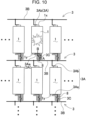
- FIG. 10 illustrates a schematic circuit diagram of a circuit that connects the plurality of batteries 1 with each other in parallel and in series.
- fuse links 3C are connected with negative sides of batteries 1, respectively.
- Fixed terminals 3A of bus bars 3 are connected with positive sides and negative sides of batteries 1.
- Fuse links 3C are connected with first fixed terminals 3Aa, respectively, that are connected with the negative sides. Therefore, fuse links 3C are connected with a half of first fixed terminals 3Aa, respectively, that are connected with the negative sides.
- bus bars 3 are connected with electrode terminals 1x, 1y of batteries 1 by spot welding or laser welding.
- batteries 1 arranged in a plurality of rows are connected with each other in parallel by bus bars 3.
- batteries 1 arranged in a plurality of columns are connected with each other in series by bus bars 3.
- the bus bars may connect batteries with each other in series that are arranged in a plurality of rows, and may connect batteries with each other in parallel that are arranged in a plurality of columns.
- Bus bars 3 are arranged on both surfaces of battery holder 2, and connect batteries 1 with each other in series and in parallel.
- Heat insulating member 8 is disposed on a surface of bus bars 3 connected with electrode terminals 1x, 1y of batteries 1. Heat insulating member 8 tightly covers at least surfaces of fuse links 3C and surfaces of fixed terminals 3A connected with fuse links 3C, respectively, at a close contact state. Heat insulating member 8 is a member that has an insulating property. Preferably, heat insulating member 8 is made of resin. Heat insulating member 8 made of resin is tightly in contact with surfaces of fuse links 3C and surfaces of fixed terminals 3A, and thus insulates fuse links 3C and fixed terminals 3A from outside. Fuse links 3C and fixed terminals 3A that are insulated by heat insulating member 8 effectively transfer heat generated by batteries 1. When an overcurrent flows through fuse links 3C, heat generated by fuse links 3C is not released to outside, and thus surely increases a temperature, and melts fuse links 3C.
- heat insulating member 8 is made of a potting resin.
- the potting resin that has not cured is paste or liquid.
- Surfaces of fuse links 3C of bus bars 3 and surfaces of fixed terminals 3A connected with fuse links 3C, respectively, are filled with potting resin that has not cured.
- the potting resin with which the surfaces of fuse links 3C and the surfaces of fixed terminals 3A are filled cures as time passes. Consequently, heat insulating member 8 is formed and is tightly fixed to the surfaces of fuse links 3C and the surfaces of fixed terminals 3A.
- An adhesive resin such as a urethane resin
- a two-part urethane resin may be used as such a potting resin.
- Main agent that is liquid at normal temperatures and hardener are stirred and mixed to polymerize the main agent and the hardener. Consequently, the two-part urethane resin that has not cured and has been paste or liquid cures.
- an epoxy resin or an unsaturated polyester resin may be used as the two-part resin.
- Resin that has been paste or liquid at normal temperatures and cures as times passes may be used as the potting resin.
- resin that has been paste or liquid at normal temperatures and is cured by heat or light may be used as the potting resin.
- the potting resin that has not cured is filled on surfaces of fuse links 3C and surfaces of fixed terminals 3A, and cures as time passes.
- the potting resin that has cured is tightly fixed to the surfaces of fuse links 3C and the surfaces of fixed terminals 3A and has excellent heat insulation.
- Heat insulating member 8 is formed to cover surfaces of the plurality of fuse links 3C of bus bars 3, and surfaces of fixed terminals 3A connected with fuse links 3C, respectively.
- Heat insulating member 8 illustrated in FIG. 6 is formed to cover whole surfaces of bus bars 3.
- potting resin that has not cured and is paste or liquid is filled into positioning hollows 2D.
- positioning hollows 2D are used as mold containers for heat insulating member 8
- potting resin that has not cured is filled into positioning hollows 2D.
- the potting resin that has been filled is cured. Consequently, heat insulating member 8 that covers whole surfaces of bus bars 3 is formed.
- bus bars 3 are fixed to bottom surfaces of positioning hollows 2D of battery holder 2.
- battery holder 2 is disposed in such a manner that openings of positioning hollows 2D face upward.
- the potting resin that has not cured is filled into positioning hollows 2D.
- the potting resin that has not cured and is filled into positioning hollows 2D spreads over surfaces of bus bars 3, and covers whole surfaces of bus bars 3.
- Potting resin that is filled into positioning hollows 2D is cured. Consequently, heat insulating member 8 covers whole surfaces of bus bars 3.
- the plurality of fuse links 3C and the plurality of fixed terminals 3A of bus bars 3 are easily covered with heat insulating member 8 formed on whole surfaces of bus bars 3. Further, as described before, the potting resin is filled into positioning hollows 2D to form heat insulating member 8. Consequently, heat insulating member 8 that has a predetermined thickness is formed on surfaces of bus bars 3. Consequently, portions of heat insulating member 8 that cover the plurality of fuse links 3C and the plurality of fixed terminals 3A have a same thickness. Consequently, a time it takes for fuse links 3C to melt is constant. Consequently, fuse links 3C surely melt when an assigned electric current flows through fuse links 3C.
- the potting resin filled to cover surfaces of fuse links 3C and surfaces of fixed terminals 3A enters hollows each formed between electrode window 7 and electrode terminals 1x, 1y, and gaps 3F each formed between fixed terminal 3A and base 3B, and gaps 3F each formed between fuse link 3C and base 3B. Consequently, the potting resin is tightly filled into surfaces of fuse links 3C and surfaces of fixed terminals 3A and into areas near fuse links 3C and fixed terminals 3A, without spaces. Therefore, heat insulating member 8 covers and insulates surfaces of electrode terminals 1x, 1y of batteries 1, or areas around fuse links 3C and fixed terminals 3A. Therefore, heat energy generated within a battery that is in an abnormal state is not released to outside, but is transferred to fuse links 3C through fixed terminals 3A. Consequently, fuse links 3C are effectively heated.
- the potting resin filled into positioning hollows 2D fixes connections between first fitting portions 3I and second fitting portions 2C.
- Heat insulating member 8 covers the connections between first fitting portions 3I and second fitting portions 2C. Therefore, heat insulating member 8 fixes both battery holder 2 and fuse-link connecting portions 3Ba at predetermined positions. Consequently, fuse links 3C and batteries 1 surely do not move relative to each other.
- the potting resin filled into positioning hollows 2D fixes connections between positioning holes 3K and positioning ribs 2F. Heat insulating member 8 covers the connections between positioning holes 3K and positioning ribs 2F. Therefore, bus bars 3 are stably fixed to predetermined positions on battery holder 2.
- Heat insulating member 8 described before covers whole surfaces of bus bars 3.
- the heat insulating member does not necessarily cover whole surfaces of the bus bars.
- Heat insulating member 8 covers, at least, surfaces of fuse links 3C of bus bars 3 and surfaces of fixed terminals 3A connected with fuse links 3C. Therefore, a heat insulating member (not shown in the figures) may be formed to separately cover surfaces of the plurality of fuse links and surfaces of the fixed terminals connected with the fuse links, respectively.
- the potting resin is separately supplied to each of the fuse links and the fixed terminals, and the heat insulating member is formed on each of the fuse links and the fixed terminals. Therefore, an amount of used potting resin is minimized. Consequently, an amount of used potting resin is reduced.
- a heat insulating member may be integrally molded to cover surfaces of a plurality of fuse links of bus bars.
- the potting resin is continuously supplied along surfaces of the bus bars. Consequently, the heat insulating member covers surfaces of all the fuse links of the bus bars.
- the structure reduces a time for which a heat insulating member is manufactured, and allows the heat insulating member to uniformly cover the fuse links since the heat insulating member that covers surfaces of the plurality of fuse links of bus bars is integrally molded.
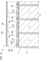
- Heat insulating member 8 may include covers 8A, as illustrated in FIG. 11 . Resin is molded into covers 8A. Covers 8A are plates or sheets into which resin is molded. For example, covers 8A are fixed to surfaces of bus bars 3 with adhesive 8B, particularly surfaces of fuse links 3C and surfaces of fixed terminals 3A. Adhesive 8B is filled into projections and hollows formed around fuse links 3C and fixed terminals 3A. Consequently, heat insulating member 8 that is illustrated in FIG. 11 and includes covers 8A and adhesive 8B is tightly fixed to surfaces of the fuse links and surfaces of the fixed terminals. Covers 8A are plates or sheets, and each have a shape that corresponds to an outer shape of bus bars 3, as illustrated in FIG. 11 .
- covers 8A are inserted into positioning hollows 2D, respectively, and each disposed along a surface of bus bar 3 and disposed at a predetermined position.
- Each of covers 8A illustrated in FIG. 11 is open at connection holes 8F.
- Connection holes 8F are at positions opposite positioning ribs 2F.
- Soft layer 8C is formed on a surface of cover 8A.
- a surface of cover 8A on which the soft layer is formed is opposite bus bar 3.
- Soft layer 8C illustrated in FIG. 12 includes projections 8D at positions opposite hollows and projections that are formed around fuse links 3C and fixed terminals 3A. Since soft layer 8C is pressed against surfaces of fuse links 3C and surfaces of fixed terminals 3A, cover 8A tightly covers surfaces of fuse links 3C and surfaces of fixed terminals 3A, and effectively insulates the surfaces of fuse links 3C and the surfaces of fixed terminals 3A. Soft layer 8C covers fuse links 3C, and functions as an impact absorber. Therefore, cover 8A improves impact resistance of fuse links 3C. If soft layer 8C is an adhesive layer, cover 8A is easily adhered to a surface of bus bar 3.
- External case 11 illustrated in FIGS. 1 to 3 accommodates battery holder 2.
- the plurality of cylindrical batteries are disposed at predetermined positions within battery holder 2.
- External case 11 illustrated in FIGS. 1 to 3 is divided into first case 11A and second case 11B.
- An accommodating portion is formed within external case 11, and accommodates battery holder 2.
- Each of first case 11A and second case 11B illustrated in FIG. 3 has a shape like a box, and has a depth that allows substantially a half of battery holder 2 to be accommodated.
- An end surface of a peripheral wall of first case 11A of external case 11 and an end surface of a peripheral wall of second case 11B of external case 11 are welded to each other by ultrasonic welding, or are connected with each other with adhesive.
- Fixing screws may be inserted into one case of the first case and the second case.
- the fixing screws may be inserted into bosses of the other case. Consequently, the first case may be connected with the second case.
- the fixing screws and the bosses are not illustrated.
- external case 11 accommodates circuit board 10.
- Electronic components such as a protection circuit, may be mounted on circuit board 10.
- Protection circuit 10 may include a detection circuit that detects a voltage, a remaining capacity, and a temperature of each of batteries 1, and switching elements switched ON or OFF based on the data of batteries 1 the detection circuit detects. The detection circuit and the switching elements are not illustrated.
- an output connector connected with the circuit board may be fixed to external case 11.
- the output connector includes an output terminal and a signal terminal. The batteries are charged and discharge through the output terminal.
- Circuit board 10 communicates with connected equipment through the signal terminal. However, the battery pack may not include the output connector.
- Connection terminals that include an output terminal and a signal terminal may be fixed to the circuit board. The connection terminals may be exposed from a bottom case, and may be connected with outside.
- heat insulating member 8 that covers fixed terminals 3A reduces release of heat from surfaces of fixed terminals 3A. Therefore, heat energy within the battery is efficiently transferred to fuse link 3C from fixed terminal 3A, as illustrated by arrow B in FIG. 10 . Consequently, fuse link 3C is effectively heated.
- an overcurrent flows through fuse link 3C, as illustrated by arrow A, and the overcurrent generates Joule heat, heat insulating member 8 that covers fuse link 3C reduces release of heat from a surface of fuse link 3C.
- fuse link 3C melts.
- heat insulating member 8 of the battery pack tightly covers surfaces of fuse links 3C and surfaces of fixed terminals 3A, heat accumulates in fixed terminals 3A and fuse links 3C, and thus fuse links 3C are effectively heated.
- the heat insulating member covers surfaces of the fuse links and surfaces of the fixed terminals of the bus bars. Consequently, a time it takes for the fuse links to melt is reduced to a time that is shorter than or equal to one third of a time it takes for conventional fuse links to melt. As shown in the fact, even if a width of the fuse links is made wide, or the fuse links are made short, and thus electrical resistance is made low, the fuse links melt rapidly compared with a conventional structure that does not include a heat insulating member.
- the heat insulating member covers surfaces of the fuse links and surfaces of the fixed terminals.
- fuse links 3C that are each elongated and S-shaped connect fixed terminals 3A with base 3B. Electrical resistance of fuse link 3C that has the shape is increased if a width of a metal sheet is narrowed, and a total length of fuse link 3C is lengthened.
- a shape of fuse links 3C of bus bars 3 of the battery pack according to an aspect of the present invention may be variously varied.
- heat insulating member 8 covers surfaces of fuse links 3C and surfaces of fixed terminals 3A connected with fuse links 3C, respectively. Therefore, fuse links 3C rapidly and surely melt even if a width of fuse links 3C is widened, and a total length of fuse links 3C is shortened. Therefore, metal sheets of the fuse links may have a wide width and a long length.
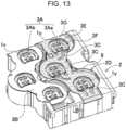
- a battery pack illustrated in FIG. 13 is a battery pack according to another exemplary embodiment of the present invention.
- a shape of fuse links 3C of bus bars is different from a shape of fuse links 3C of bus bars 3 described before.
- Fuse links 3C of bus bars 3 illustrated in FIG. 13 connect steps 3D of fixed terminals 3A with base 3B.
- a shape of fuse links 3C is like a strip that has a uniform width.
- a shape of some fuse links 3C is like a strip that is curved at approximately 90 degrees and has a predetermined radius of curvature.
- a shape of other fuse links 3C is like a strip that extends straight.
- Fuse links 3C of bus bars 3 in FIG. 13 are wider and shorter than fuse links 3C of bus bars 3 described before.
- a heat insulating member covers fuse links 3C of bus bars 3 and fixed terminals 3A connected with fuse links 3C, respectively. Therefore, fuse links 3C rapidly melt. Therefore, even if a width of fuse links 3C is widened, and short fuse links 3C are designed as illustrated in FIG. 13 , fuse links 3C surely melt at a predetermined assigned temperature.
- some bus bars 3 each include a plurality of fuse links 3C, and fixed terminals 3A connected with fuse links 3C, respectively, and connected with electrode terminals 1y, respectively (first fixed terminals 3Aa).
- Heat insulating member 8 covers fuse links 3C and fixed terminals 3A.
- other bus bars 3 each include a plurality of fixed terminals 3A connected with electrode terminals 1x, respectively (second fixed terminals 3Ab).
- Heat insulating member is not on surfaces of other bus bars 3.
- heat insulating member 8 covers fuse links 3C and fixed terminals 3A connected with fuse links 3C. Fixed terminals 3A that are not connected with fuse links 3C may not be covered with the heat insulating member.
- the present invention is effectively applicable to a battery pack that accommodates a plurality of batteries in a battery holder, and includes fuse links connected with the batteries to improve safety.
Landscapes
- Chemical & Material Sciences (AREA)
- Chemical Kinetics & Catalysis (AREA)
- Electrochemistry (AREA)
- General Chemical & Material Sciences (AREA)
- Engineering & Computer Science (AREA)
- Manufacturing & Machinery (AREA)
- Inorganic Chemistry (AREA)
- Connection Of Batteries Or Terminals (AREA)
- Battery Mounting, Suspending (AREA)
- Secondary Cells (AREA)
Claims (8)
- Bloc-batterie comprenant :une pluralité de batteries (1) qui peuvent être chargées et déchargées ;un support de batterie (2) qui agence les batteries à des positions prédéterminées ; etune barre omnibus (3) qui est une feuille métallique fixée à des bornes d'électrodes (1x, 1y) des batteries (1),dans lequella barre omnibus (3) comporte :une pluralité de bornes fixes (3A) connectées aux bornes d'électrodes (1x, 1y) des batteries (1) ;une base (3B) qui connecte la pluralité de batteries (1) les unes aux autres par l'intermédiaire de la pluralité de bornes fixes (3A) en série et/ou en parallèle ; etdes éléments fusibles (3C) qui comportent des extrémités qui sont connectées aux bornes fixes (3A), respectivement, et des racines qui sont connectées à la base (3B), etle bloc-batterie comprend en outre un organe d'isolation thermique (8) qui recouvre de manière étanche les surfaces des éléments fusibles (3C) et les surfaces des bornes fixes (3A) connectées aux éléments fusibles (3C), respectivement.
- Bloc-batterie selon la revendication 1, dans lequel l'organe d'isolation thermique (8) est réalisé en une résine d'enrobage.
- Bloc-batterie selon la revendication 1, dans lequel l'organe d'isolation thermique (8) comporte un couvercle (8A) moulé avec de la résine, et le couvercle (8A) est fixé de manière étanche aux surfaces des éléments fusibles (3C) et aux surfaces des bornes fixes (3A) connectées aux éléments fusibles (3C), respectivement.
- Bloc-batterie selon l'une quelconque des revendications 1 à 3, dans lequel la barre omnibus (3) comporte la pluralité d'éléments fusibles (3C), et l'organe d'isolation thermique (8) est moulé d'un seul tenant pour couvrir de manière étanche les surfaces de tous les éléments fusibles (3C) de la barre omnibus (3).
- Bloc-batterie selon la revendication 4, dans lequel l'organe d'isolation thermique (8) est sur toute la surface de la barre omnibus (3).
- Bloc-batterie selon l'une quelconque des revendications 1 à 5, dans lequelle support de batterie (2) place la pluralité de batteries (1) parallèlement les unes aux autres, et agence, sur les mêmes plans, les bornes d'électrodes (1x, 1y) aux deux extrémités des batteries (1), et la barre omnibus (3) connecte les bornes d'électrodes (1x, 1y) des batteries (1) les unes aux autres sur chacune des deux surfaces du support de batterie (2), etle support de batterie (2) comporte un creux de positionnement (2D) sur chacune des deux surfaces sur lesquelles sont agencées les bornes d'électrodes (1x, 1y) des batteries (1), la barre omnibus (3) est disposée dans le creux de positionnement (2D), et l'organe d'isolation thermique (8) est disposé dans le creux de positionnement (2D).
- Bloc-batterie selon l'une quelconque des revendications 1 à 6, dans lequella base (3B) comporte des parties de connexion d'élément fusible (3Ba) qui sont connectées aux racines des éléments fusibles (3C), respectivement, et les parties de connexion d'élément fusible (3Ba) comportent des premières parties d'ajustement (31), respectivement,le support de batterie (2) comporte des deuxièmes parties d'ajustement (2C), et les deuxièmes parties d'ajustement (2C) sont connectées aux premières parties d'ajustement (31), respectivement, et les deuxièmes parties d'ajustement (2C) sont connectées aux parties de connexion d'élément fusible (3Ba), respectivement,les deuxièmes parties d'ajustement (2C) sont connectées aux premières parties d'ajustement (31), respectivement, et les parties de connexion d'élément fusible (3Ba) sont connectées au support de batterie (2), etl'organe d'isolation thermique (8) fixe des connexions entre les premières parties d'ajustement (31) et les deuxièmes parties d'ajustement (2C).
- Bloc-batterie selon l'une quelconque des revendications 1 à 7, dans lequella base (3B) de la barre omnibus (3) comporte un trou de positionnement (3K) entre les bornes fixes (3A) qui sont adjacentes les unes aux autres,le support de batterie (2) comporte une nervure de positionnement (2F) qui est guidée par le trou de positionnement (3K) et connectée à la barre omnibus (3),la nervure de positionnement (2F) est connectée au trou de positionnement (3K), et la barre omnibus (3) est connectée au support de batterie, etl'organe d'isolation thermique (8) fixe une connexion entre le trou de positionnement (3K) et la nervure de positionnement (2F).
Applications Claiming Priority (2)
| Application Number | Priority Date | Filing Date | Title |
|---|---|---|---|
| JP2017106025 | 2017-05-29 | ||
| PCT/JP2018/014675 WO2018221004A1 (fr) | 2017-05-29 | 2018-04-06 | Bloc-batterie |
Publications (4)
| Publication Number | Publication Date |
|---|---|
| EP3633764A1 EP3633764A1 (fr) | 2020-04-08 |
| EP3633764A4 EP3633764A4 (fr) | 2020-06-17 |
| EP3633764B1 true EP3633764B1 (fr) | 2023-05-24 |
| EP3633764B8 EP3633764B8 (fr) | 2023-05-31 |
Family
ID=64454691
Family Applications (1)
| Application Number | Title | Priority Date | Filing Date |
|---|---|---|---|
| EP18810608.2A Active EP3633764B8 (fr) | 2017-05-29 | 2018-04-06 | Bloc-batterie |
Country Status (5)
| Country | Link |
|---|---|
| US (1) | US11201364B2 (fr) |
| EP (1) | EP3633764B8 (fr) |
| JP (1) | JP7027415B2 (fr) |
| CN (1) | CN110710026A (fr) |
| WO (1) | WO2018221004A1 (fr) |
Cited By (1)
| Publication number | Priority date | Publication date | Assignee | Title |
|---|---|---|---|---|
| WO2024251447A1 (fr) * | 2023-06-05 | 2024-12-12 | Bayerische Motoren Werke Aktiengesellschaft | Dispositif de stockage d'énergie électrique pour un véhicule à moteur, en particulier pour une automobile, et véhicule à moteur |
Families Citing this family (47)
| Publication number | Priority date | Publication date | Assignee | Title |
|---|---|---|---|---|
| US11063320B2 (en) * | 2019-01-08 | 2021-07-13 | Lg Chem, Ltd. | Terminal busbar |
| EP4358654A3 (fr) * | 2019-03-28 | 2024-12-04 | CPS Technology Holdings LLC | Circuit flexible avec fusible, support de barre omnibus comprenant une structure d'entrée, ensemble de conduction électrique avec barre omnibus et batterie le comprenant |
| NO347942B1 (en) * | 2019-05-28 | 2024-05-21 | Grenland Energy As | A battery module |
| US12580276B2 (en) * | 2019-08-30 | 2026-03-17 | Panasonic Intellectual Property Management Co., Ltd. | Electrical storage module |
| KR102820678B1 (ko) | 2019-09-24 | 2025-06-12 | 주식회사 엘지에너지솔루션 | 버스바 플레이트를 포함하는 배터리 모듈, 그것을 포함하는 배터리 팩, 및 전자 디바이스 |
| KR102805857B1 (ko) * | 2019-10-10 | 2025-05-12 | 주식회사 엘지에너지솔루션 | 단열부재를 포함하는 전지모듈 및 이를 포함하는 전지팩 |
| JP7326494B2 (ja) * | 2019-10-11 | 2023-08-15 | エルジー エナジー ソリューション リミテッド | バスバープレートを含むバッテリーモジュール、それを含むバッテリーパック及び電子デバイス |
| KR102952461B1 (ko) * | 2019-10-11 | 2026-04-14 | 주식회사 엘지에너지솔루션 | 버스바 플레이트를 포함하는 배터리 모듈, 그것을 포함하는 배터리 팩, 및 전자 디바이스 |
| KR102765963B1 (ko) * | 2019-11-25 | 2025-02-07 | 주식회사 엘지에너지솔루션 | 배터리 모듈 및 배터리 팩 |
| KR102533159B1 (ko) | 2019-11-29 | 2023-05-17 | 삼성에스디아이 주식회사 | 배터리 팩 |
| KR102561801B1 (ko) | 2019-11-29 | 2023-07-31 | 삼성에스디아이 주식회사 | 배터리 팩 |
| KR20210067647A (ko) | 2019-11-29 | 2021-06-08 | 삼성에스디아이 주식회사 | 배터리 팩 |
| KR102501080B1 (ko) | 2019-11-29 | 2023-02-17 | 삼성에스디아이 주식회사 | 배터리 팩 |
| KR102572650B1 (ko) * | 2019-11-29 | 2023-08-31 | 삼성에스디아이 주식회사 | 배터리 팩 |
| KR102574517B1 (ko) | 2019-11-29 | 2023-09-04 | 삼성에스디아이 주식회사 | 배터리 팩 |
| KR102873394B1 (ko) * | 2019-12-04 | 2025-10-17 | 주식회사 엘지에너지솔루션 | 배터리 모듈 및 배터리 팩 |
| JP7338488B2 (ja) * | 2020-01-23 | 2023-09-05 | トヨタ自動車株式会社 | 電池 |
| CN115210945B (zh) * | 2020-03-05 | 2024-08-23 | 株式会社村田制作所 | 电池包、电动工具及电动车辆 |
| KR102792413B1 (ko) * | 2020-03-09 | 2025-04-04 | 주식회사 엘지에너지솔루션 | 버스바를 구비한 배터리 모듈, 및 배터리 팩, 및 자동차 |
| AT523391B1 (de) * | 2020-03-30 | 2021-08-15 | Kreisel Electric Gmbh & Co Kg | Vorrichtung mit einem Rahmen, der Aufnahmen für die stirnseitigen Endabschnitte von bezüglich ihrer Längsachse parallel ausgerichteten Batteriezellen aufweist |
| WO2021252597A1 (fr) * | 2020-06-11 | 2021-12-16 | Milwaukee Electric Tool Corporation | Bloc-batterie |
| EP3926704A1 (fr) * | 2020-06-18 | 2021-12-22 | VARTA Microbattery GmbH | Module de batterie à refroidissement par air |
| KR102819871B1 (ko) * | 2020-09-04 | 2025-06-11 | 주식회사 엘지에너지솔루션 | 배터리 모듈, 및 배터리 팩, 및 자동차 |
| KR102908125B1 (ko) * | 2021-01-11 | 2026-01-05 | 주식회사 엘지에너지솔루션 | 배터리 팩 및 이를 포함하는 자동차 |
| ES3063627T3 (en) * | 2021-01-11 | 2026-04-17 | Lg Energy Solution Ltd | Battery pack and vehicle comprising same |
| EP4618254A3 (fr) * | 2021-03-04 | 2025-11-19 | LG Energy Solution, Ltd. | Bloc-batterie et véhicule le comprenant |
| KR20220128310A (ko) * | 2021-03-12 | 2022-09-20 | 주식회사 엘지에너지솔루션 | 버스바 어셈블리, 이러한 버스바 어셈블리를 포함하는 배터리 팩 및 이러한 배터리 팩을 포함하는 자동차 |
| KR20220158539A (ko) * | 2021-05-24 | 2022-12-01 | 삼성에스디아이 주식회사 | 배터리 팩 |
| JP7537390B2 (ja) * | 2021-07-19 | 2024-08-21 | トヨタ自動車株式会社 | 蓄電装置 |
| US12347893B2 (en) | 2021-09-17 | 2025-07-01 | Techtronic Cordless Gp | Battery pack |
| US20230113884A1 (en) * | 2021-10-12 | 2023-04-13 | Lg Energy Solution, Ltd. | Battery pack and vehicle including the same |
| US12463283B2 (en) | 2021-10-12 | 2025-11-04 | Lg Energy Solution, Ltd. | Battery pack and vehicle including the same |
| US20230111495A1 (en) * | 2021-10-12 | 2023-04-13 | Lg Energy Solution, Ltd. | Battery pack and vehicle including the same |
| JP7455793B2 (ja) | 2021-11-17 | 2024-03-26 | プライムプラネットエナジー&ソリューションズ株式会社 | 電池モジュール |
| US12525683B2 (en) | 2022-05-12 | 2026-01-13 | Ford Global Technologies, Llc | Filtering assembly for battery array of a traction battery and filtering method |
| CN218482327U (zh) * | 2022-07-15 | 2023-02-14 | 富士能电子(昆山)有限公司 | 防延烧电池模块 |
| DE102022213649A1 (de) * | 2022-12-14 | 2024-06-20 | Robert Bosch Gesellschaft mit beschränkter Haftung | Energiespeichereinheit für einen elektrischen Verbraucher |
| CN116093557A (zh) * | 2022-12-29 | 2023-05-09 | 中国电子科技集团公司第十八研究所 | 一种绝缘组合热电池机构及其制备方法 |
| WO2024219873A1 (fr) * | 2023-04-20 | 2024-10-24 | 주식회사 엘지에너지솔루션 | Module de batterie et bloc-batterie le comprenant |
| US12542330B2 (en) | 2023-06-30 | 2026-02-03 | Rivian Ip Holdings, Llc | Battery subassembly with potting material |
| US12525671B2 (en) | 2023-06-30 | 2026-01-13 | Rivian Ip Holdings, Llc | Battery welds |
| US12471245B2 (en) | 2023-06-30 | 2025-11-11 | Rivian Ip Holdings, Llc | Cold plate |
| EP4507089A3 (fr) * | 2023-08-11 | 2025-06-18 | Schneider Electric IT Corporation | Procédés et systèmes de découplage de batteries en cas d'emballement thermique |
| DE102024101954A1 (de) * | 2024-01-24 | 2025-07-24 | Bayerische Motoren Werke Aktiengesellschaft | Zellverbund sowie Hochvoltspeicher mit Zellverbund |
| DE102024128164A1 (de) * | 2024-09-27 | 2026-04-02 | Elringklinger Ag | Zellkontaktiersystem und Batteriemodul oder Pack |
| DE102024128165A1 (de) * | 2024-09-27 | 2026-04-02 | Elringklinger Ag | Zellkontaktiersystem in einem Batteriemodul oder Pack |
| JP7748635B1 (ja) * | 2025-03-21 | 2025-10-03 | パナソニックIpマネジメント株式会社 | 電池モジュール |
Family Cites Families (21)
| Publication number | Priority date | Publication date | Assignee | Title |
|---|---|---|---|---|
| JP2002075329A (ja) * | 2000-08-31 | 2002-03-15 | Matsushita Electric Ind Co Ltd | Ptc素子の取付方法及びこれを用いた電池パック |
| KR101084213B1 (ko) * | 2009-11-30 | 2011-11-17 | 삼성에스디아이 주식회사 | 전지 팩 |
| JP2012182047A (ja) * | 2011-03-02 | 2012-09-20 | Auto Network Gijutsu Kenkyusho:Kk | バスバーセット及びその製造方法 |
| US9159985B2 (en) * | 2011-05-27 | 2015-10-13 | Ostuka Techno Corporation | Circuit breaker and battery pack including the same |
| WO2012164884A1 (fr) * | 2011-05-31 | 2012-12-06 | パナソニック株式会社 | Tableau de fusibles et bloc-batterie équipé de celui-ci |
| CN103718341A (zh) * | 2011-08-08 | 2014-04-09 | 罗杰斯公司 | 包括柔性电路的汇流排 |
| JP5761164B2 (ja) * | 2012-11-30 | 2015-08-12 | トヨタ自動車株式会社 | 組電池 |
| JP6018937B2 (ja) | 2013-01-29 | 2016-11-02 | 三洋電機株式会社 | 電極部材、および、電池ブロック |
| US20140272490A1 (en) * | 2013-03-12 | 2014-09-18 | Samsung Sdi Co., Ltd. | Rechargeable battery |
| JP6223725B2 (ja) * | 2013-06-12 | 2017-11-01 | 新光電気工業株式会社 | 電池及びその製造方法 |
| KR102084098B1 (ko) * | 2013-09-23 | 2020-03-04 | 삼성에스디아이 주식회사 | 홀더를 갖는 전지 모듈 |
| JP2015097174A (ja) | 2013-11-15 | 2015-05-21 | 日立オートモティブシステムズ株式会社 | 二次電池 |
| JP6211425B2 (ja) | 2014-01-28 | 2017-10-11 | ダイキョーニシカワ株式会社 | 電池モジュール |
| JP6295901B2 (ja) | 2014-09-24 | 2018-03-20 | トヨタ自動車株式会社 | 蓄電装置 |
| JP6775109B2 (ja) * | 2014-11-04 | 2020-10-28 | パナソニックIpマネジメント株式会社 | 電極部材および集電板、電池ブロック |
| US20160315304A1 (en) * | 2015-04-21 | 2016-10-27 | Atieva, Inc. | Encapsulated Fusible Interconnect |
| JP6376405B2 (ja) * | 2015-05-28 | 2018-08-22 | 豊田合成株式会社 | 電池モジュール |
| JP6249991B2 (ja) * | 2015-06-10 | 2017-12-20 | 矢崎総業株式会社 | 配線モジュール |
| JP2017084606A (ja) * | 2015-10-28 | 2017-05-18 | トヨタ自動車株式会社 | 電池接続構造 |
| CN105470557B (zh) * | 2015-11-25 | 2018-05-29 | 亿和精密工业(苏州)有限公司 | 锂离子电池组的保险板 |
| JP6524051B2 (ja) * | 2016-12-09 | 2019-06-05 | 矢崎総業株式会社 | 導体の接続構造および導電モジュール |
-
2018
- 2018-04-06 CN CN201880035110.8A patent/CN110710026A/zh active Pending
- 2018-04-06 WO PCT/JP2018/014675 patent/WO2018221004A1/fr not_active Ceased
- 2018-04-06 EP EP18810608.2A patent/EP3633764B8/fr active Active
- 2018-04-06 JP JP2019521988A patent/JP7027415B2/ja active Active
- 2018-04-06 US US16/615,258 patent/US11201364B2/en active Active
Cited By (1)
| Publication number | Priority date | Publication date | Assignee | Title |
|---|---|---|---|---|
| WO2024251447A1 (fr) * | 2023-06-05 | 2024-12-12 | Bayerische Motoren Werke Aktiengesellschaft | Dispositif de stockage d'énergie électrique pour un véhicule à moteur, en particulier pour une automobile, et véhicule à moteur |
Also Published As
| Publication number | Publication date |
|---|---|
| JP7027415B2 (ja) | 2022-03-01 |
| EP3633764A4 (fr) | 2020-06-17 |
| JPWO2018221004A1 (ja) | 2020-03-26 |
| US20200076022A1 (en) | 2020-03-05 |
| US11201364B2 (en) | 2021-12-14 |
| EP3633764B8 (fr) | 2023-05-31 |
| CN110710026A (zh) | 2020-01-17 |
| WO2018221004A1 (fr) | 2018-12-06 |
| EP3633764A1 (fr) | 2020-04-08 |
Similar Documents
| Publication | Publication Date | Title |
|---|---|---|
| EP3633764B1 (fr) | Bloc-batterie | |
| EP3651237B1 (fr) | Bloc-batterie à structure d'assemblage améliorée | |
| KR102235655B1 (ko) | 이차 전지 팩 | |
| CN101490871B (zh) | 中型或大型电池组模块 | |
| JP2023529119A (ja) | バスバーアセンブリ、このようなバスバーアセンブリを含むバッテリーパック、及びこのようなバッテリーパックを含む自動車 | |
| JP7337047B2 (ja) | 電池パック | |
| TW201126791A (en) | Battery system with a plurality of batteries housed in an external case | |
| KR20050036751A (ko) | 카트리지 타입의 전지팩 | |
| KR20200067587A (ko) | 전지팩 | |
| KR20100081942A (ko) | 신규한 구조의 전지모듈 및 이를 포함하는 중대형 전지팩 | |
| KR102916626B1 (ko) | 리무버블 퓨즈 어셈블리를 구비한 배터리 모듈 및 이를 포함하는 배터리 팩 | |
| CN112602163A (zh) | 具有可熔连片的汽车电池导体板 | |
| KR102233501B1 (ko) | 이차 전지용 다기능 구조체 및 이를 포함하는 이차 전지 팩 | |
| EP3279972B1 (fr) | Module de batterie | |
| JP5244513B2 (ja) | 電池パック | |
| KR102295950B1 (ko) | 이차 전지용 냉각 지지 구조체 및 이를 포함하는 이차 전지 팩 | |
| CN114270608B (zh) | 蓄电模块 | |
| KR20080020317A (ko) | 배터리 팩 및 이의 제조 방법 | |
| EP4084212B1 (fr) | Bloc-batterie comprenant un support de boîte à fusibles pour la prévention de court-circuit | |
| WO2018179794A1 (fr) | Bloc-batterie | |
| JP7266935B2 (ja) | 電池モジュールおよびそれを含む電池パック | |
| KR20170040638A (ko) | 배터리 모듈 및 이를 포함하는 배터리 팩 | |
| US20210391602A1 (en) | Battery cell interconnect system | |
| JP7325890B2 (ja) | 電池モジュールおよびこれを含む電池パック | |
| WO2017169729A1 (fr) | Bloc-batterie |
Legal Events
| Date | Code | Title | Description |
|---|---|---|---|
| STAA | Information on the status of an ep patent application or granted ep patent |
Free format text: STATUS: THE INTERNATIONAL PUBLICATION HAS BEEN MADE |
|
| PUAI | Public reference made under article 153(3) epc to a published international application that has entered the european phase |
Free format text: ORIGINAL CODE: 0009012 |
|
| STAA | Information on the status of an ep patent application or granted ep patent |
Free format text: STATUS: REQUEST FOR EXAMINATION WAS MADE |
|
| 17P | Request for examination filed |
Effective date: 20191106 |
|
| AK | Designated contracting states |
Kind code of ref document: A1 Designated state(s): AL AT BE BG CH CY CZ DE DK EE ES FI FR GB GR HR HU IE IS IT LI LT LU LV MC MK MT NL NO PL PT RO RS SE SI SK SM TR |
|
| AX | Request for extension of the european patent |
Extension state: BA ME |
|
| A4 | Supplementary search report drawn up and despatched |
Effective date: 20200520 |
|
| RIC1 | Information provided on ipc code assigned before grant |
Ipc: H01M 2/34 20060101ALI20200514BHEP Ipc: H01M 2/10 20060101ALI20200514BHEP Ipc: H01M 2/20 20060101AFI20200514BHEP |
|
| DAV | Request for validation of the european patent (deleted) | ||
| DAX | Request for extension of the european patent (deleted) | ||
| REG | Reference to a national code |
Ref country code: DE Ref legal event code: R079 Ref document number: 602018050248 Country of ref document: DE Free format text: PREVIOUS MAIN CLASS: H01M0002200000 Ipc: H01M0050505000 |
|
| RIC1 | Information provided on ipc code assigned before grant |
Ipc: H01M 50/581 20210101ALI20221020BHEP Ipc: H01M 50/505 20210101AFI20221020BHEP |
|
| GRAP | Despatch of communication of intention to grant a patent |
Free format text: ORIGINAL CODE: EPIDOSNIGR1 |
|
| STAA | Information on the status of an ep patent application or granted ep patent |
Free format text: STATUS: GRANT OF PATENT IS INTENDED |
|
| INTG | Intention to grant announced |
Effective date: 20221206 |
|
| GRAS | Grant fee paid |
Free format text: ORIGINAL CODE: EPIDOSNIGR3 |
|
| GRAA | (expected) grant |
Free format text: ORIGINAL CODE: 0009210 |
|
| STAA | Information on the status of an ep patent application or granted ep patent |
Free format text: STATUS: THE PATENT HAS BEEN GRANTED |
|
| GRAT | Correction requested after decision to grant or after decision to maintain patent in amended form |
Free format text: ORIGINAL CODE: EPIDOSNCDEC |
|
| REG | Reference to a national code |
Ref country code: DE Ref legal event code: R081 Ref document number: 602018050248 Country of ref document: DE Owner name: PANASONIC ENERGY CO., LTD., MORIGUCHI-SHI, JP Free format text: FORMER OWNER: SANYO ELECTRIC CO., LTD., DAITO-SHI, OSAKA, JP |
|
| AK | Designated contracting states |
Kind code of ref document: B1 Designated state(s): AL AT BE BG CH CY CZ DE DK EE ES FI FR GB GR HR HU IE IS IT LI LT LU LV MC MK MT NL NO PL PT RO RS SE SI SK SM TR |
|
| REG | Reference to a national code |
Ref country code: GB Ref legal event code: FG4D |
|
| RAP4 | Party data changed (patent owner data changed or rights of a patent transferred) |
Owner name: SANYO ELECTRIC CO., LTD. |
|
| REG | Reference to a national code |
Ref country code: CH Ref legal event code: EP |
|
| REG | Reference to a national code |
Ref country code: DE Ref legal event code: R096 Ref document number: 602018050248 Country of ref document: DE |
|
| REG | Reference to a national code |
Ref country code: AT Ref legal event code: REF Ref document number: 1570123 Country of ref document: AT Kind code of ref document: T Effective date: 20230615 |
|
| REG | Reference to a national code |
Ref country code: IE Ref legal event code: FG4D |
|
| REG | Reference to a national code |
Ref country code: DE Ref legal event code: R081 Ref document number: 602018050248 Country of ref document: DE Owner name: PANASONIC ENERGY CO., LTD., MORIGUCHI-SHI, JP Free format text: FORMER OWNER: SANYO ELECTRIC CO., LTD., KADOMA-SHI, OSAKA, JP |
|
| RAP2 | Party data changed (patent owner data changed or rights of a patent transferred) |
Owner name: PANASONIC ENERGY CO., LTD. |
|
| REG | Reference to a national code |
Ref country code: LT Ref legal event code: MG9D |
|
| REG | Reference to a national code |
Ref country code: NL Ref legal event code: MP Effective date: 20230524 |
|
| REG | Reference to a national code |
Ref country code: GB Ref legal event code: 732E Free format text: REGISTERED BETWEEN 20230907 AND 20230913 |
|
| REG | Reference to a national code |
Ref country code: AT Ref legal event code: MK05 Ref document number: 1570123 Country of ref document: AT Kind code of ref document: T Effective date: 20230524 |
|
| PG25 | Lapsed in a contracting state [announced via postgrant information from national office to epo] |
Ref country code: SE Free format text: LAPSE BECAUSE OF FAILURE TO SUBMIT A TRANSLATION OF THE DESCRIPTION OR TO PAY THE FEE WITHIN THE PRESCRIBED TIME-LIMIT Effective date: 20230524 Ref country code: PT Free format text: LAPSE BECAUSE OF FAILURE TO SUBMIT A TRANSLATION OF THE DESCRIPTION OR TO PAY THE FEE WITHIN THE PRESCRIBED TIME-LIMIT Effective date: 20230925 Ref country code: NO Free format text: LAPSE BECAUSE OF FAILURE TO SUBMIT A TRANSLATION OF THE DESCRIPTION OR TO PAY THE FEE WITHIN THE PRESCRIBED TIME-LIMIT Effective date: 20230824 Ref country code: NL Free format text: LAPSE BECAUSE OF FAILURE TO SUBMIT A TRANSLATION OF THE DESCRIPTION OR TO PAY THE FEE WITHIN THE PRESCRIBED TIME-LIMIT Effective date: 20230524 Ref country code: ES Free format text: LAPSE BECAUSE OF FAILURE TO SUBMIT A TRANSLATION OF THE DESCRIPTION OR TO PAY THE FEE WITHIN THE PRESCRIBED TIME-LIMIT Effective date: 20230524 Ref country code: AT Free format text: LAPSE BECAUSE OF FAILURE TO SUBMIT A TRANSLATION OF THE DESCRIPTION OR TO PAY THE FEE WITHIN THE PRESCRIBED TIME-LIMIT Effective date: 20230524 |
|
| PG25 | Lapsed in a contracting state [announced via postgrant information from national office to epo] |
Ref country code: RS Free format text: LAPSE BECAUSE OF FAILURE TO SUBMIT A TRANSLATION OF THE DESCRIPTION OR TO PAY THE FEE WITHIN THE PRESCRIBED TIME-LIMIT Effective date: 20230524 Ref country code: PL Free format text: LAPSE BECAUSE OF FAILURE TO SUBMIT A TRANSLATION OF THE DESCRIPTION OR TO PAY THE FEE WITHIN THE PRESCRIBED TIME-LIMIT Effective date: 20230524 Ref country code: LV Free format text: LAPSE BECAUSE OF FAILURE TO SUBMIT A TRANSLATION OF THE DESCRIPTION OR TO PAY THE FEE WITHIN THE PRESCRIBED TIME-LIMIT Effective date: 20230524 Ref country code: LT Free format text: LAPSE BECAUSE OF FAILURE TO SUBMIT A TRANSLATION OF THE DESCRIPTION OR TO PAY THE FEE WITHIN THE PRESCRIBED TIME-LIMIT Effective date: 20230524 Ref country code: IS Free format text: LAPSE BECAUSE OF FAILURE TO SUBMIT A TRANSLATION OF THE DESCRIPTION OR TO PAY THE FEE WITHIN THE PRESCRIBED TIME-LIMIT Effective date: 20230924 Ref country code: HR Free format text: LAPSE BECAUSE OF FAILURE TO SUBMIT A TRANSLATION OF THE DESCRIPTION OR TO PAY THE FEE WITHIN THE PRESCRIBED TIME-LIMIT Effective date: 20230524 Ref country code: GR Free format text: LAPSE BECAUSE OF FAILURE TO SUBMIT A TRANSLATION OF THE DESCRIPTION OR TO PAY THE FEE WITHIN THE PRESCRIBED TIME-LIMIT Effective date: 20230825 |
|
| PG25 | Lapsed in a contracting state [announced via postgrant information from national office to epo] |
Ref country code: FI Free format text: LAPSE BECAUSE OF FAILURE TO SUBMIT A TRANSLATION OF THE DESCRIPTION OR TO PAY THE FEE WITHIN THE PRESCRIBED TIME-LIMIT Effective date: 20230524 |
|
| PG25 | Lapsed in a contracting state [announced via postgrant information from national office to epo] |
Ref country code: SK Free format text: LAPSE BECAUSE OF FAILURE TO SUBMIT A TRANSLATION OF THE DESCRIPTION OR TO PAY THE FEE WITHIN THE PRESCRIBED TIME-LIMIT Effective date: 20230524 |
|
| PG25 | Lapsed in a contracting state [announced via postgrant information from national office to epo] |
Ref country code: SM Free format text: LAPSE BECAUSE OF FAILURE TO SUBMIT A TRANSLATION OF THE DESCRIPTION OR TO PAY THE FEE WITHIN THE PRESCRIBED TIME-LIMIT Effective date: 20230524 Ref country code: SK Free format text: LAPSE BECAUSE OF FAILURE TO SUBMIT A TRANSLATION OF THE DESCRIPTION OR TO PAY THE FEE WITHIN THE PRESCRIBED TIME-LIMIT Effective date: 20230524 Ref country code: RO Free format text: LAPSE BECAUSE OF FAILURE TO SUBMIT A TRANSLATION OF THE DESCRIPTION OR TO PAY THE FEE WITHIN THE PRESCRIBED TIME-LIMIT Effective date: 20230524 Ref country code: EE Free format text: LAPSE BECAUSE OF FAILURE TO SUBMIT A TRANSLATION OF THE DESCRIPTION OR TO PAY THE FEE WITHIN THE PRESCRIBED TIME-LIMIT Effective date: 20230524 Ref country code: DK Free format text: LAPSE BECAUSE OF FAILURE TO SUBMIT A TRANSLATION OF THE DESCRIPTION OR TO PAY THE FEE WITHIN THE PRESCRIBED TIME-LIMIT Effective date: 20230524 Ref country code: CZ Free format text: LAPSE BECAUSE OF FAILURE TO SUBMIT A TRANSLATION OF THE DESCRIPTION OR TO PAY THE FEE WITHIN THE PRESCRIBED TIME-LIMIT Effective date: 20230524 |
|
| REG | Reference to a national code |
Ref country code: DE Ref legal event code: R097 Ref document number: 602018050248 Country of ref document: DE |
|
| PLBE | No opposition filed within time limit |
Free format text: ORIGINAL CODE: 0009261 |
|
| STAA | Information on the status of an ep patent application or granted ep patent |
Free format text: STATUS: NO OPPOSITION FILED WITHIN TIME LIMIT |
|
| 26N | No opposition filed |
Effective date: 20240227 |
|
| PG25 | Lapsed in a contracting state [announced via postgrant information from national office to epo] |
Ref country code: SI Free format text: LAPSE BECAUSE OF FAILURE TO SUBMIT A TRANSLATION OF THE DESCRIPTION OR TO PAY THE FEE WITHIN THE PRESCRIBED TIME-LIMIT Effective date: 20230524 |
|
| PG25 | Lapsed in a contracting state [announced via postgrant information from national office to epo] |
Ref country code: SI Free format text: LAPSE BECAUSE OF FAILURE TO SUBMIT A TRANSLATION OF THE DESCRIPTION OR TO PAY THE FEE WITHIN THE PRESCRIBED TIME-LIMIT Effective date: 20230524 Ref country code: IT Free format text: LAPSE BECAUSE OF FAILURE TO SUBMIT A TRANSLATION OF THE DESCRIPTION OR TO PAY THE FEE WITHIN THE PRESCRIBED TIME-LIMIT Effective date: 20230524 |
|
| PG25 | Lapsed in a contracting state [announced via postgrant information from national office to epo] |
Ref country code: BG Free format text: LAPSE BECAUSE OF FAILURE TO SUBMIT A TRANSLATION OF THE DESCRIPTION OR TO PAY THE FEE WITHIN THE PRESCRIBED TIME-LIMIT Effective date: 20230524 |
|
| PG25 | Lapsed in a contracting state [announced via postgrant information from national office to epo] |
Ref country code: MC Free format text: LAPSE BECAUSE OF FAILURE TO SUBMIT A TRANSLATION OF THE DESCRIPTION OR TO PAY THE FEE WITHIN THE PRESCRIBED TIME-LIMIT Effective date: 20230524 |
|
| PG25 | Lapsed in a contracting state [announced via postgrant information from national office to epo] |
Ref country code: MC Free format text: LAPSE BECAUSE OF FAILURE TO SUBMIT A TRANSLATION OF THE DESCRIPTION OR TO PAY THE FEE WITHIN THE PRESCRIBED TIME-LIMIT Effective date: 20230524 Ref country code: BG Free format text: LAPSE BECAUSE OF FAILURE TO SUBMIT A TRANSLATION OF THE DESCRIPTION OR TO PAY THE FEE WITHIN THE PRESCRIBED TIME-LIMIT Effective date: 20230524 |
|
| REG | Reference to a national code |
Ref country code: CH Ref legal event code: PL |
|
| PG25 | Lapsed in a contracting state [announced via postgrant information from national office to epo] |
Ref country code: LU Free format text: LAPSE BECAUSE OF NON-PAYMENT OF DUE FEES Effective date: 20240406 |
|
| REG | Reference to a national code |
Ref country code: BE Ref legal event code: MM Effective date: 20240430 |
|
| PG25 | Lapsed in a contracting state [announced via postgrant information from national office to epo] |
Ref country code: LU Free format text: LAPSE BECAUSE OF NON-PAYMENT OF DUE FEES Effective date: 20240406 |
|
| PG25 | Lapsed in a contracting state [announced via postgrant information from national office to epo] |
Ref country code: BE Free format text: LAPSE BECAUSE OF NON-PAYMENT OF DUE FEES Effective date: 20240430 |
|
| PG25 | Lapsed in a contracting state [announced via postgrant information from national office to epo] |
Ref country code: BE Free format text: LAPSE BECAUSE OF NON-PAYMENT OF DUE FEES Effective date: 20240430 Ref country code: CH Free format text: LAPSE BECAUSE OF NON-PAYMENT OF DUE FEES Effective date: 20240430 |
|
| PG25 | Lapsed in a contracting state [announced via postgrant information from national office to epo] |
Ref country code: IE Free format text: LAPSE BECAUSE OF NON-PAYMENT OF DUE FEES Effective date: 20240406 |
|
| PGFP | Annual fee paid to national office [announced via postgrant information from national office to epo] |
Ref country code: DE Payment date: 20250422 Year of fee payment: 8 |
|
| PGFP | Annual fee paid to national office [announced via postgrant information from national office to epo] |
Ref country code: GB Payment date: 20250423 Year of fee payment: 8 |
|
| PGFP | Annual fee paid to national office [announced via postgrant information from national office to epo] |
Ref country code: FR Payment date: 20250425 Year of fee payment: 8 |
|
| PG25 | Lapsed in a contracting state [announced via postgrant information from national office to epo] |
Ref country code: CY Free format text: LAPSE BECAUSE OF FAILURE TO SUBMIT A TRANSLATION OF THE DESCRIPTION OR TO PAY THE FEE WITHIN THE PRESCRIBED TIME-LIMIT; INVALID AB INITIO Effective date: 20180406 |
|
| PG25 | Lapsed in a contracting state [announced via postgrant information from national office to epo] |
Ref country code: HU Free format text: LAPSE BECAUSE OF FAILURE TO SUBMIT A TRANSLATION OF THE DESCRIPTION OR TO PAY THE FEE WITHIN THE PRESCRIBED TIME-LIMIT; INVALID AB INITIO Effective date: 20180406 |
|
| PG25 | Lapsed in a contracting state [announced via postgrant information from national office to epo] |
Ref country code: TR Free format text: LAPSE BECAUSE OF FAILURE TO SUBMIT A TRANSLATION OF THE DESCRIPTION OR TO PAY THE FEE WITHIN THE PRESCRIBED TIME-LIMIT Effective date: 20230524 |