EP3633811A1 - Circuit de protection - Google Patents
Circuit de protection Download PDFInfo
- Publication number
- EP3633811A1 EP3633811A1 EP18198162.2A EP18198162A EP3633811A1 EP 3633811 A1 EP3633811 A1 EP 3633811A1 EP 18198162 A EP18198162 A EP 18198162A EP 3633811 A1 EP3633811 A1 EP 3633811A1
- Authority
- EP
- European Patent Office
- Prior art keywords
- protection circuit
- transistor switch
- inrush current
- link
- voltage
- Prior art date
- Legal status (The legal status is an assumption and is not a legal conclusion. Google has not performed a legal analysis and makes no representation as to the accuracy of the status listed.)
- Withdrawn
Links
- 239000003990 capacitor Substances 0.000 claims description 45
- 238000000034 method Methods 0.000 claims description 29
- 238000006243 chemical reaction Methods 0.000 claims description 20
- 230000000630 rising effect Effects 0.000 claims description 3
- 238000001514 detection method Methods 0.000 description 2
- 230000001419 dependent effect Effects 0.000 description 1
- 230000008030 elimination Effects 0.000 description 1
- 238000003379 elimination reaction Methods 0.000 description 1
- 238000004146 energy storage Methods 0.000 description 1
- 239000002360 explosive Substances 0.000 description 1
- 238000007689 inspection Methods 0.000 description 1
- 238000002955 isolation Methods 0.000 description 1
- 229920006395 saturated elastomer Polymers 0.000 description 1
- 230000007704 transition Effects 0.000 description 1
Images


Classifications
-
- H—ELECTRICITY
- H02—GENERATION; CONVERSION OR DISTRIBUTION OF ELECTRIC POWER
- H02H—EMERGENCY PROTECTIVE CIRCUIT ARRANGEMENTS
- H02H9/00—Emergency protective circuit arrangements for limiting excess current or voltage without disconnection
- H02H9/001—Emergency protective circuit arrangements for limiting excess current or voltage without disconnection limiting speed of change of electric quantities, e.g. soft switching on or off
-
- H—ELECTRICITY
- H02—GENERATION; CONVERSION OR DISTRIBUTION OF ELECTRIC POWER
- H02H—EMERGENCY PROTECTIVE CIRCUIT ARRANGEMENTS
- H02H3/00—Emergency protective circuit arrangements for automatic disconnection directly responsive to an undesired change from normal electric working condition with or without subsequent reconnection ; integrated protection
- H02H3/08—Emergency protective circuit arrangements for automatic disconnection directly responsive to an undesired change from normal electric working condition with or without subsequent reconnection ; integrated protection responsive to excess current
- H02H3/087—Emergency protective circuit arrangements for automatic disconnection directly responsive to an undesired change from normal electric working condition with or without subsequent reconnection ; integrated protection responsive to excess current for DC applications
-
- H—ELECTRICITY
- H02—GENERATION; CONVERSION OR DISTRIBUTION OF ELECTRIC POWER
- H02H—EMERGENCY PROTECTIVE CIRCUIT ARRANGEMENTS
- H02H7/00—Emergency protective circuit arrangements specially adapted for specific types of electric machines or apparatus or for sectionalised protection of cable or line systems, and effecting automatic switching in the event of an undesired change from normal working conditions
- H02H7/10—Emergency protective circuit arrangements specially adapted for specific types of electric machines or apparatus or for sectionalised protection of cable or line systems, and effecting automatic switching in the event of an undesired change from normal working conditions for converters; for rectifiers
- H02H7/12—Emergency protective circuit arrangements specially adapted for specific types of electric machines or apparatus or for sectionalised protection of cable or line systems, and effecting automatic switching in the event of an undesired change from normal working conditions for converters; for rectifiers for static converters or rectifiers
- H02H7/1216—Emergency protective circuit arrangements specially adapted for specific types of electric machines or apparatus or for sectionalised protection of cable or line systems, and effecting automatic switching in the event of an undesired change from normal working conditions for converters; for rectifiers for static converters or rectifiers for AC-AC converters
-
- H—ELECTRICITY
- H02—GENERATION; CONVERSION OR DISTRIBUTION OF ELECTRIC POWER
- H02H—EMERGENCY PROTECTIVE CIRCUIT ARRANGEMENTS
- H02H7/00—Emergency protective circuit arrangements specially adapted for specific types of electric machines or apparatus or for sectionalised protection of cable or line systems, and effecting automatic switching in the event of an undesired change from normal working conditions
- H02H7/10—Emergency protective circuit arrangements specially adapted for specific types of electric machines or apparatus or for sectionalised protection of cable or line systems, and effecting automatic switching in the event of an undesired change from normal working conditions for converters; for rectifiers
- H02H7/12—Emergency protective circuit arrangements specially adapted for specific types of electric machines or apparatus or for sectionalised protection of cable or line systems, and effecting automatic switching in the event of an undesired change from normal working conditions for converters; for rectifiers for static converters or rectifiers
- H02H7/125—Emergency protective circuit arrangements specially adapted for specific types of electric machines or apparatus or for sectionalised protection of cable or line systems, and effecting automatic switching in the event of an undesired change from normal working conditions for converters; for rectifiers for static converters or rectifiers for rectifiers
-
- H—ELECTRICITY
- H02—GENERATION; CONVERSION OR DISTRIBUTION OF ELECTRIC POWER
- H02H—EMERGENCY PROTECTIVE CIRCUIT ARRANGEMENTS
- H02H7/00—Emergency protective circuit arrangements specially adapted for specific types of electric machines or apparatus or for sectionalised protection of cable or line systems, and effecting automatic switching in the event of an undesired change from normal working conditions
- H02H7/16—Emergency protective circuit arrangements specially adapted for specific types of electric machines or apparatus or for sectionalised protection of cable or line systems, and effecting automatic switching in the event of an undesired change from normal working conditions for capacitors
-
- H—ELECTRICITY
- H02—GENERATION; CONVERSION OR DISTRIBUTION OF ELECTRIC POWER
- H02H—EMERGENCY PROTECTIVE CIRCUIT ARRANGEMENTS
- H02H9/00—Emergency protective circuit arrangements for limiting excess current or voltage without disconnection
- H02H9/02—Emergency protective circuit arrangements for limiting excess current or voltage without disconnection responsive to excess current
-
- H—ELECTRICITY
- H02—GENERATION; CONVERSION OR DISTRIBUTION OF ELECTRIC POWER
- H02H—EMERGENCY PROTECTIVE CIRCUIT ARRANGEMENTS
- H02H9/00—Emergency protective circuit arrangements for limiting excess current or voltage without disconnection
- H02H9/02—Emergency protective circuit arrangements for limiting excess current or voltage without disconnection responsive to excess current
- H02H9/026—Current limitation using PTC resistors, i.e. resistors with a large positive temperature coefficient
Definitions
- the present disclosure relates to protection circuits, in particular to a protection circuits suitable for preventing damage to DC link capacitors and other components coupled to the DC link of an electrical conversion system.
- DC link capacitors play an important role in electrical conversion systems that incorporate a DC link between stages.
- a DC link is often provided between an AC grid and an inverter that generates a suitable AC output to drive the motor.
- the DC link capacitors ensure that the voltage on the DC link remains relatively stable as the inverter draws in power to be supplied to the motor.
- the requirements for low series resistance and high energy storage capacity while operating at a high DC link voltage mean that often a series connected pair of DC link capacitors is used, with half the DC link voltage being applied across each.
- series connected DC link capacitors to share the DC link voltage, it is difficult to design for safe operation of the system in the event of component failure or accidental short circuit of the DC link.
- the patent application EP 2 833 499 describes a DC link capacitor protection circuit.
- a resistive divider is connected in parallel with a series connection of DC link capacitors.
- the mid-points of the DC link capacitors and the resistive divider should have the same voltage, but those voltages will differ in the event of a DC link capacitor fault (such as a short circuit).
- the DC link capacitor protection circuit includes a diode bridge that provides an output using an optocoupler when the mid-point voltages differ by more than a defined amount. In response to that output from the diode bridge, an input stage for charging the DC link capacitors is deactivated.
- a protection circuit comprising an inrush current detector operable to detect an inrush current from a DC link, wherein the inrush current detector comprises a transistor switch that is turned on in normal operation of the protection circuit, and wherein the protection circuit operates to detect when the voltage across the transistor switch exceeds a threshold voltage in response to a detected inrush current, and in response operates to turn off the transistor switch.
- an inrush current can pass directly into the transistor of the protection circuit to enable rapid isolation of supply to the DC link.
- the transistor is provided in series with a DC link capacitor, between a DC link capacitor and a DC negative line, such that the protection circuit operates to detect when the voltage across the transistor switch exceeds a threshold voltage in response to a detected inrush current from the DC link capacitor.
- the transistor switch is provided in series with an input rectifier, between the input rectifier and a DC negative line, such that the protection circuit operates to detect when the voltage across the transistor switch exceeds a threshold voltage in response to a detected inrush current from the DC negative line.
- the inrush current detector comprises a gate driver circuit arranged to control the transistor switch.
- the inrush current detector comprises a transistor switch biased by a gate driver circuit so as to be turned on in normal operation of the protection circuit.
- the inrush current detector comprises a transistor switch that is biased by a gate driver circuit so as to operate in its saturation region in normal operation of the protection circuit.
- the inrush current detector detects the inrush current and operates the gate driver circuit to turn off the transistor switch in response to the detected inrush current, and thereby isolate the DC link.
- the inrush current detector is arranged to detect an inrush current from the DC link by detecting that the voltage across the transistor switch exceeds a threshold voltage. In one example the inrush current detector is arranged to detect an inrush current from the DC link by detecting a predetermined threshold voltage across the transistor switch. In one example the predetermined threshold voltage corresponds to a maximum allowed inrush current at the transistor switch.
- inrush current detector is arranged to detect an inrush current from the DC link by detecting that the voltage across the transistor switch exceeds a threshold voltage, the threshold voltage corresponding to desaturation of the transistor switch.
- the transistor switch comprises an IGBT.
- inrush current detector is arranged to detect an inrush current from the DC link according to the collector-emitter voltage of the transistor switch.
- IGBTs are available which demonstrate a relatively sharp transition to saturation behaviour even when subjected to high current. Although relatively slower to turn off than other transistor switches, the cost of producing the protection circuit with an IGBT transistor switch may also be relatively lower than for other transistor switches that may be required for a protection circuit rated to a particular voltage.
- the transistor switch comprises a FET, such as a MOSFET / SiC MOSFET, or comprises a GaN based MOSFET, MESFET or HEMT device.
- inrush current detector is arranged to detect an inrush current from the DC link according to the drain-source voltage of the transistor switch.
- MOSFET devices may demonstrate relatively fast turn off times that are desirable for fast detection and DC link fault protection operation, but compared to IGBTs generally have a higher cost per unit area.
- the protection circuit further is further provided with a current limiting resistor connected in parallel to the transistor switch.
- the current limiting resistor comprises a positive temperature coefficient thermistor.
- the protection circuit further comprises a fault notification terminal, and is arranged to output a fault notification signal to the fault notification terminal after the protection circuit isolates the DC link in response a detected inrush current.
- the protection circuit may be readily integrated with other protection or control circuits, for easier fault notification/diagnostic operations.
- the protection circuit further comprises an input-shut down terminal and is arranged to output an input-shut down signal to the input shut-down terminal after the protection circuit isolates the DC link in response a detected inrush current.
- the protection circuit may enable powering down of the supply from which the DC link is fed.
- a power conversion system including a protection circuit as herein-described.
- the power conversion system operates between an input supply and a load, for example between an input supply and a motor drive.
- the protection circuit is provided integral with a motor drive.
- the power conversion system comprises an inverter, with the protection circuit arranged to operate prior to initialisation of the inverter to provide protection for the DC link on inverter initialisation.
- a method of protecting components coupled to a DC link comprising detecting an inrush current from the DC link in a protection circuit which comprises a transistor switch that is turned on in normal operation of the protection circuit, and, in response to the detected inrush current turning off the transistor switch, wherein the detecting step is performed by detecting when the voltage across the transistor switch exceeds a threshold voltage.
- the transistor switch is provided in series with a DC link capacitor, between a DC link capacitor and a DC negative line, such that the protection circuit operates to detect when the voltage across the transistor switch exceeds a threshold voltage in response to a detected inrush current from the DC link capacitor.
- the transistor switch is provided in series with an input rectifier, between the input rectifier and a DC negative line, such that the protection circuit operates to detect when the voltage across the transistor switch exceeds a threshold voltage in response to a detected inrush current from the DC negative line.
- the method comprises operating a gate driver circuit to turn off the transistor switch in response to the detected inrush current.
- the method comprises detecting desaturation of the transistor switch, according to a collector-emitter voltage of the transistor switch rising above the threshold voltage.
- the method comprises passing an inrush current through a current limiting resistor connected in parallel to the transistor switch. In one example, the method comprises passing an inrush current through a current limiting resistor connected in parallel to the transistor switch during a start up operation of the protection circuit. In one example, the method comprises passing an inrush current through a current limiting resistor connected in parallel to the transistor switch while the transistor is turned off. In one example, the method comprises passing an inrush current through a current limiting resistor in the form of a positive temperature coefficient thermistor connected in parallel to the transistor switch.
- the method further comprises powering down the supply from which the DC link is fed.
- the method further comprises outputting a fault notification signal. In one example, the method comprises outputting a fault notification signal after the protection circuit isolates the DC link in response a detected inrush current.
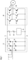
- Figure 1 shows a schematic overview of a power conversion system including a protection circuit 20 according to an example embodiment.
- the protection circuit 20 is provided in series with DC link capacitors C1 and C2, connected between a DC positive line 11 and a DC negative line 12.
- To the left side of the protection circuit 20 are three input lines L1, L2 and L3, which feed diodes D1-D6 arranged as a rectifier 10.
- To the right side of the protection circuit 20 is an inverter 30 represented schematically by switches Z1-Z6.
- the inverter 30 operates under the control of a control unit (not shown) to operate as a drive for the motor M which is coupled to three output lines 01, O2 and O3 from the inverter 30.
- the connection between the rectifier 10 and the inverter 30, made up of the DC positive line 11 and DC negative line 12, comprises the DC link.
- the protection circuit 20 comprises an inrush current detector, and is operable to detect an inrush current from the DC link. In response to detection of an inrush current from the DC link the protection circuit 20 is arranged to isolate the DC link. This protects the DC link capacitors C1, C2, the switches Z1-Z6 in the inverter 30, and indeed any other electronic components coupled to the DC link from damage by short circuit, component failure of one of the DC link capacitors C1, C2 or similar.
- Figure 2 shows the power conversion system of Figure 1 , along with a positive temperature coefficient thermistor, PTC connected in parallel therewith.
- the PTC is connected in parallel to the transistor switch Q1 of the protection circuit 20 and serves as a current limiter on start up.
- the resistance of the current limiting positive temperature coefficient thermistor, PTC is normally low, but rapidly rises in the event of an inrush current from the DC link at times when the protection circuit 20 isolates the DC link.
- the current limiting positive temperature coefficient thermistor, PTC serves to reduce peak current flowing from the DC link capacitor C2 during start up operation of the protection circuit 20, enabling charge to build up on the DC link capacitors C1, C2.
- the protection circuit 20 becomes operational ready to isolate the DC link if a fault condition is sensed.
- the operation of a PTC on start up is enabled by a relay provided in parallel with the PTC.
- the relay On start up the relay is open so that the PTC can operate to control inrush current from the DC link and to allow charge to build up on the DC link capacitors. Thereafter the relay is closed.
- start up operation is facilitated without a separate relay and thus costs of implementing safe start up and protection are reduced. Elimination of the relay used at start up has advantages of increased reliability and suitability for use in explosive environments.
- Figure 3 shows a power conversion system comprising a protection circuit 20 according to another example embodiment, along with a positive temperature coefficient thermistor, PTC, connected in parallel therewith.
- the inrush current detector comprises a transistor switch Q1 and its associated gate driver circuit 21.
- the transistor switch Q1 is provided as an IGBT with anti-parallel snubber diode, in series with the DC link capacitors C1, C2.
- the transistor switch Q1 is connected between the DC link capacitor C2 at its collector and the DC negative line at its emitter. In normal operation of the protection circuit 20, a gate drive voltage is provided to the transistor switch Q1 by gate driver circuit 21 of the protection circuit 20 such that transistor switch Q1 is turned on, operating in its saturation region.
- the gate driver circuit 21 is fed, at pin 6, from a +18V supply that is independent of power on DC link.
- the +18V supply is referenced to 0V and negative supply pins 2 and 3 of the gate driver circuit 21 respectively, these pins being tied to one another.
- the +18V supply is also fed to pin 1 of the gate driver circuit.
- the +18V supply is still further fed via an input switching circuit 24 to pin 3 of the gate driver circuit 21, such that provision of an enable signal to the switch-on circuit 24 switches on transistor switch Q2, enabling the operation of the gate driver circuit 21 thereafter.
- the gate driver circuit 21 provides the gate drive voltage to the gate of the transistor Q1 from pin 5, through a filter 22.
- the transistor switch Q1 is able to detect an inrush current from the DC link because the voltage across the transistor switch Q1 is a function of the current flowing through Q1 from collector to emitter. By detecting a threshold voltage across the transistor switch Q1, it may be inferred that an inrush current is taking place at the transistor switch Q1. In particular, if a short circuit event occurs and the full DC link voltage is applied to the transistor switch Q1, the collector current of Q1 increases to a level that drives the transistor switch Q1 out of the saturated region and into its linear region of operation. This results in a rapid increase in the collector-emitter voltage, which is detected by the gate driver circuit 21 via filter 23. In response the gate driver circuit 21 rapidly adjusts its output at pin 5 to turn off the transistor switch Q1.
- a current limiting positive temperature coefficient thermistor, PTC is connected in parallel to the transistor switch Q1 of the protection circuit 20.
- the resistance of the current limiting positive temperature coefficient thermistor, PTC is normally low, but rapidly rises in the event of an inrush current from the DC link at a time when the transistor switch Q1 is turned off.
- the current limiting positive temperature coefficient thermistor, PTC serves to reduce peak current flowing from the DC link capacitor C2 during start up operation of the protection circuit 20, enabling charge to build up on the DC link capacitors C1, C2.
- the protection circuit 20 becomes operational with the transistor switch Q1 turned on but ready to be turned off by the gate driver circuit 21 if an inrush current related to a fault condition is sensed.
- the gate driver circuit 21 further comprises, at pin 7, a fault notification terminal.
- the gate driver circuit 21 outputs a fault notification signal to the fault notification terminal after the protection circuit isolates the DC link in response a detected inrush current.
- the fault notification terminal enables the protection circuit 20 to be integrated with other protection or control circuits. This can either be to a human operator, or to enable further automatic safety interventions such as use of a signal at the fault notification terminal to as an input shut-down control to switch off supply to the input lines L1, L2 and L3 after the protection circuit 20 has isolated the DC link in response a detected inrush current.
- FIG 4A shows a schematic overview of a power conversion system including a protection circuit according to an example embodiment, in an arrangement similar to Figure 1 .
- the protection circuit 20 is provided in series with the DC link capacitors C1, C2, and additionally a relay S1 and parallel PTC provided in order to deal with start up.
- FIG. 4B shows a schematic overview of a power conversion system including a protection circuit according to an example embodiment.
- a relay S1 and PTC are provided in order to deal with start up.
- the protection circuit 20 is provided in series with the rectifier at the input side of the DC negative line. Providing the protection circuit 20 in this arrangement serves to protect the DC link capacitors C1, C2 and the switching components of the rectifier connected to the output side of power conversion system.
- Figure 4C shows a schematic overview of a power conversion system including a protection circuit according to an example embodiment.
- the protection circuit 20 is provided in series with the rectifier at the input side of the DC negative line. Providing the protection circuit 20 in this arrangement serves to protect the DC link capacitors C1, C2 and the switching components of the rectifier connected to the output side of power conversion system.
- a PTC is provided in parallel with the protection circuit 20, in an arrangement similar to Figure 2 .
- Figure 5 shows steps in a method of protecting components coupled to a DC link, according to an example embodiment.
- the method may be performed by a protection circuit as set out herein.
- the method comprises detecting an inrush current from the DC link in a protection circuit connected in series with a DC link capacitor (S1), and isolating the DC link in response to the detected inrush current (S2-S4).
- the method comprises detecting that a desaturation voltage has been reached according to a collector-emitter voltage of the transistor switch rising above a predetermined threshold voltage, S1. In response the transistor switch is turned off, S2. As an optional step, after the detecting and switching off of S1 and S2 take place, any further inrush current is exposed to a positive temperature coefficient thermistor connected in parallel to the transistor switch, S3.
- the method may further comprise one or more additional optional steps of powering down the supply from which the DC link is fed, and sending a fault signal to one or more users, S4.
- the protection circuit is also useful when incorporated with motor drives.
- Some safety certification organisations such as Underwriters Laboratory Inc., may require a motor drive to be able to withstand deliberate short-circuiting of one of paired of DC link capacitors in order to pass their certification.
- Implementing the protection circuit in a motor drive may reduce costs by eliminating the need for separate testing/certification, enabling safe operation alongside any other protection measures such as circuit breakers/fuses that may be desirable according to particular design or service requirements.
- providing a protection circuit that can also facilitate safe switch on behaviour, without the need for additional switching components such as a relay is also advantageous.
Landscapes
- Engineering & Computer Science (AREA)
- Power Engineering (AREA)
- Rectifiers (AREA)
- Inverter Devices (AREA)
- Emergency Protection Circuit Devices (AREA)
Priority Applications (5)
| Application Number | Priority Date | Filing Date | Title |
|---|---|---|---|
| EP18198162.2A EP3633811A1 (fr) | 2018-10-02 | 2018-10-02 | Circuit de protection |
| CN201980065258.0A CN112789777B (zh) | 2018-10-02 | 2019-09-23 | 保护电路 |
| PCT/EP2019/075499 WO2020069894A1 (fr) | 2018-10-02 | 2019-09-23 | Circuit de protection |
| US17/279,773 US11764566B2 (en) | 2018-10-02 | 2019-09-23 | Protection circuit |
| EP19786447.3A EP3861612A1 (fr) | 2018-10-02 | 2019-09-23 | Circuit de protection |
Applications Claiming Priority (1)
| Application Number | Priority Date | Filing Date | Title |
|---|---|---|---|
| EP18198162.2A EP3633811A1 (fr) | 2018-10-02 | 2018-10-02 | Circuit de protection |
Publications (1)
| Publication Number | Publication Date |
|---|---|
| EP3633811A1 true EP3633811A1 (fr) | 2020-04-08 |
Family
ID=63722202
Family Applications (2)
| Application Number | Title | Priority Date | Filing Date |
|---|---|---|---|
| EP18198162.2A Withdrawn EP3633811A1 (fr) | 2018-10-02 | 2018-10-02 | Circuit de protection |
| EP19786447.3A Pending EP3861612A1 (fr) | 2018-10-02 | 2019-09-23 | Circuit de protection |
Family Applications After (1)
| Application Number | Title | Priority Date | Filing Date |
|---|---|---|---|
| EP19786447.3A Pending EP3861612A1 (fr) | 2018-10-02 | 2019-09-23 | Circuit de protection |
Country Status (4)
| Country | Link |
|---|---|
| US (1) | US11764566B2 (fr) |
| EP (2) | EP3633811A1 (fr) |
| CN (1) | CN112789777B (fr) |
| WO (1) | WO2020069894A1 (fr) |
Cited By (1)
| Publication number | Priority date | Publication date | Assignee | Title |
|---|---|---|---|---|
| CN115694447A (zh) * | 2021-07-28 | 2023-02-03 | 通用汽车环球科技运作有限责任公司 | 用于双向开关的短路保护 |
Families Citing this family (5)
| Publication number | Priority date | Publication date | Assignee | Title |
|---|---|---|---|---|
| CN111788752A (zh) * | 2020-05-25 | 2020-10-16 | 深圳市锐明技术股份有限公司 | 一种保护电路、硬盘设备的电源系统以及车载设备 |
| CN114785159B (zh) * | 2022-04-29 | 2025-12-23 | 广东威灵电机制造有限公司 | 稳压电路、电机控制电路、电机和电器设备 |
| CN114914887B (zh) * | 2022-06-20 | 2023-11-14 | 江苏莱提电气股份有限公司 | 应用于apf的三相过流检测保护系统及过流保护设备 |
| FR3153948A1 (fr) * | 2023-10-05 | 2025-04-11 | Valeo Eautomotive Germany Gmbh | Composant électronique destiné à être embarqué sur un véhicule |
| GB202405399D0 (en) * | 2024-04-17 | 2024-05-29 | Rolls Royce Plc | Electrical power system |
Citations (7)
| Publication number | Priority date | Publication date | Assignee | Title |
|---|---|---|---|---|
| JPS63178759A (ja) * | 1987-01-20 | 1988-07-22 | Fujitsu Ltd | 突入電流防止回路 |
| US5436824A (en) * | 1992-12-10 | 1995-07-25 | Rosemount Inc. | Inrush current limiter in a magnetic flowmeter |
| EP2400649A1 (fr) * | 2009-02-17 | 2011-12-28 | Shin-Kobe Electric Machinery Co., Ltd. | Dispositif d'alimentation électrique |
| EP2639949A1 (fr) * | 2012-03-13 | 2013-09-18 | Siemens Aktiengesellschaft | Alimentation en courant avec circuit intermédiaire |
| EP2833499A1 (fr) | 2013-08-01 | 2015-02-04 | Danfoss Power Electronics A/S | Circuit de protection de condensateur de liaison CC |
| EP3182572A1 (fr) * | 2015-12-17 | 2017-06-21 | Grundfos Holding A/S | Circuit électronique et procédé de fonctionnement associé |
| US20180183228A1 (en) * | 2016-12-22 | 2018-06-28 | Infineon Technologies Austria Ag | System and method for desaturation detection |
Family Cites Families (8)
| Publication number | Priority date | Publication date | Assignee | Title |
|---|---|---|---|---|
| US3935511A (en) * | 1973-12-26 | 1976-01-27 | Texas Instruments Incorporated | Current inrush limiter |
| TW522623B (en) * | 2001-06-13 | 2003-03-01 | Delta Electronics Inc | Inrush current protection circuit |
| US6744644B2 (en) * | 2001-10-02 | 2004-06-01 | Honeywell International Inc. | Soft-start of DC link capacitors for power electronics and drive systems |
| JP5483419B2 (ja) * | 2009-12-08 | 2014-05-07 | Necライティング株式会社 | スイッチ回路の突入電流防止回路 |
| JP2011167012A (ja) * | 2010-02-12 | 2011-08-25 | Nec Corp | 突入電流防止回路及び突入電流の防止方法 |
| DE102013202641A1 (de) * | 2013-02-19 | 2014-08-21 | Robert Bosch Gmbh | Schutzvorrichtung für einen Halbleiterschalter und Verfahren zum Betreiben einer Schutzvorrichtung für einen Halbleiterschalter |
| CN110710090B (zh) * | 2017-07-14 | 2022-01-14 | 丹佛斯电力电子有限公司 | Dc链路电容器保护 |
| US11114844B2 (en) * | 2018-07-20 | 2021-09-07 | Vertiv Corporation | Inrush current limiter circuits and methods of limiting inrush current in a circuit |
-
2018
- 2018-10-02 EP EP18198162.2A patent/EP3633811A1/fr not_active Withdrawn
-
2019
- 2019-09-23 WO PCT/EP2019/075499 patent/WO2020069894A1/fr not_active Ceased
- 2019-09-23 US US17/279,773 patent/US11764566B2/en active Active
- 2019-09-23 CN CN201980065258.0A patent/CN112789777B/zh active Active
- 2019-09-23 EP EP19786447.3A patent/EP3861612A1/fr active Pending
Patent Citations (7)
| Publication number | Priority date | Publication date | Assignee | Title |
|---|---|---|---|---|
| JPS63178759A (ja) * | 1987-01-20 | 1988-07-22 | Fujitsu Ltd | 突入電流防止回路 |
| US5436824A (en) * | 1992-12-10 | 1995-07-25 | Rosemount Inc. | Inrush current limiter in a magnetic flowmeter |
| EP2400649A1 (fr) * | 2009-02-17 | 2011-12-28 | Shin-Kobe Electric Machinery Co., Ltd. | Dispositif d'alimentation électrique |
| EP2639949A1 (fr) * | 2012-03-13 | 2013-09-18 | Siemens Aktiengesellschaft | Alimentation en courant avec circuit intermédiaire |
| EP2833499A1 (fr) | 2013-08-01 | 2015-02-04 | Danfoss Power Electronics A/S | Circuit de protection de condensateur de liaison CC |
| EP3182572A1 (fr) * | 2015-12-17 | 2017-06-21 | Grundfos Holding A/S | Circuit électronique et procédé de fonctionnement associé |
| US20180183228A1 (en) * | 2016-12-22 | 2018-06-28 | Infineon Technologies Austria Ag | System and method for desaturation detection |
Cited By (1)
| Publication number | Priority date | Publication date | Assignee | Title |
|---|---|---|---|---|
| CN115694447A (zh) * | 2021-07-28 | 2023-02-03 | 通用汽车环球科技运作有限责任公司 | 用于双向开关的短路保护 |
Also Published As
| Publication number | Publication date |
|---|---|
| WO2020069894A1 (fr) | 2020-04-09 |
| EP3861612A1 (fr) | 2021-08-11 |
| CN112789777B (zh) | 2024-02-20 |
| US11764566B2 (en) | 2023-09-19 |
| US20210344188A1 (en) | 2021-11-04 |
| CN112789777A (zh) | 2021-05-11 |
Similar Documents
| Publication | Publication Date | Title |
|---|---|---|
| US11764566B2 (en) | Protection circuit | |
| US6396721B1 (en) | Power converter control device and power converter thereof | |
| CN117767226A (zh) | 具有集成固态断路器的可调速驱动及其操作方法 | |
| US9667055B2 (en) | Over-voltage protection apparatus and method of operating the same | |
| CN102545639B (zh) | 用于调节直流电压的电路和方法以及电力转换器 | |
| US20180205262A1 (en) | Power supply device and switch control method therefor | |
| CN108696155B (zh) | 转换器装置和功率元件的故障检测方法 | |
| US6178077B1 (en) | Electronic branch switching device | |
| EP2747260B1 (fr) | Procédé pour faire fonctionner un redresseur de puissance électrique et redresseur de puissance électrique | |
| CN110268493B (zh) | 低电压保护开关单元 | |
| JP2016127737A (ja) | 電力変換装置の保護装置 | |
| EP4463922B1 (fr) | Dispositif de limitation de tension pour circuits à courant constant | |
| US12015334B2 (en) | Power electronic device | |
| US10291159B2 (en) | Control system, controller, and control method for wound induction machine | |
| US12334294B2 (en) | Power supply device | |
| US20230039409A1 (en) | Power supply apparatus | |
| US12199422B2 (en) | Systems and methods for overcurrent protection | |
| KR102514585B1 (ko) | 디지털 보호 계전기 및 이의 제어 방법 | |
| US12512746B2 (en) | Gate drive circuit and power conversion device | |
| CN220342024U (zh) | 电压保护电路和漏电保护装置 | |
| US11381193B2 (en) | Embedded electronic motor disconnect | |
| CN110797836B (zh) | 用于电机驱动器中的开关电源的电路、操作方法和电机驱动电路系统 | |
| JPH05268722A (ja) | インバータ装置の誤配線保護回路 | |
| KR20010003354A (ko) | 전원공급장치의 고전압 입력 차단장치 | |
| JPH04295226A (ja) | 電気供給装置 |
Legal Events
| Date | Code | Title | Description |
|---|---|---|---|
| PUAI | Public reference made under article 153(3) epc to a published international application that has entered the european phase |
Free format text: ORIGINAL CODE: 0009012 |
|
| STAA | Information on the status of an ep patent application or granted ep patent |
Free format text: STATUS: THE APPLICATION HAS BEEN PUBLISHED |
|
| AK | Designated contracting states |
Kind code of ref document: A1 Designated state(s): AL AT BE BG CH CY CZ DE DK EE ES FI FR GB GR HR HU IE IS IT LI LT LU LV MC MK MT NL NO PL PT RO RS SE SI SK SM TR |
|
| AX | Request for extension of the european patent |
Extension state: BA ME |
|
| RIN1 | Information on inventor provided before grant (corrected) |
Inventor name: LONSDALE, PETER Inventor name: CHEN, YIRAN |
|
| STAA | Information on the status of an ep patent application or granted ep patent |
Free format text: STATUS: THE APPLICATION IS DEEMED TO BE WITHDRAWN |
|
| 18D | Application deemed to be withdrawn |
Effective date: 20201009 |