EP3633877B1 - Procédé de détection des discontinuités dans un canal optique, en particulier dans une conduite en fibre de verre - Google Patents
Procédé de détection des discontinuités dans un canal optique, en particulier dans une conduite en fibre de verre Download PDFInfo
- Publication number
- EP3633877B1 EP3633877B1 EP19200901.7A EP19200901A EP3633877B1 EP 3633877 B1 EP3633877 B1 EP 3633877B1 EP 19200901 A EP19200901 A EP 19200901A EP 3633877 B1 EP3633877 B1 EP 3633877B1
- Authority
- EP
- European Patent Office
- Prior art keywords
- frequency
- laser
- lasers
- control unit
- test pulse
- Prior art date
- Legal status (The legal status is an assumption and is not a legal conclusion. Google has not performed a legal analysis and makes no representation as to the accuracy of the status listed.)
- Not-in-force
Links
Images


Classifications
-
- G—PHYSICS
- G01—MEASURING; TESTING
- G01M—TESTING STATIC OR DYNAMIC BALANCE OF MACHINES OR STRUCTURES; TESTING OF STRUCTURES OR APPARATUS, NOT OTHERWISE PROVIDED FOR
- G01M11/00—Testing of optical apparatus; Testing structures by optical methods not otherwise provided for
- G01M11/30—Testing of optical devices, constituted by fibre optics or optical waveguides
- G01M11/31—Testing of optical devices, constituted by fibre optics or optical waveguides with a light emitter and a light receiver being disposed at the same side of a fibre or waveguide end-face, e.g. reflectometers
- G01M11/3109—Reflectometers detecting the back-scattered light in the time-domain, e.g. OTDR
- G01M11/3136—Reflectometers detecting the back-scattered light in the time-domain, e.g. OTDR for testing of multiple fibers
-
- G—PHYSICS
- G01—MEASURING; TESTING
- G01M—TESTING STATIC OR DYNAMIC BALANCE OF MACHINES OR STRUCTURES; TESTING OF STRUCTURES OR APPARATUS, NOT OTHERWISE PROVIDED FOR
- G01M11/00—Testing of optical apparatus; Testing structures by optical methods not otherwise provided for
- G01M11/08—Testing mechanical properties
- G01M11/088—Testing mechanical properties of optical fibres; Mechanical features associated with the optical testing of optical fibres
-
- G—PHYSICS
- G01—MEASURING; TESTING
- G01M—TESTING STATIC OR DYNAMIC BALANCE OF MACHINES OR STRUCTURES; TESTING OF STRUCTURES OR APPARATUS, NOT OTHERWISE PROVIDED FOR
- G01M11/00—Testing of optical apparatus; Testing structures by optical methods not otherwise provided for
- G01M11/02—Testing optical properties
- G01M11/0207—Details of measuring devices
-
- G—PHYSICS
- G01—MEASURING; TESTING
- G01M—TESTING STATIC OR DYNAMIC BALANCE OF MACHINES OR STRUCTURES; TESTING OF STRUCTURES OR APPARATUS, NOT OTHERWISE PROVIDED FOR
- G01M11/00—Testing of optical apparatus; Testing structures by optical methods not otherwise provided for
- G01M11/30—Testing of optical devices, constituted by fibre optics or optical waveguides
-
- G—PHYSICS
- G01—MEASURING; TESTING
- G01M—TESTING STATIC OR DYNAMIC BALANCE OF MACHINES OR STRUCTURES; TESTING OF STRUCTURES OR APPARATUS, NOT OTHERWISE PROVIDED FOR
- G01M11/00—Testing of optical apparatus; Testing structures by optical methods not otherwise provided for
- G01M11/30—Testing of optical devices, constituted by fibre optics or optical waveguides
- G01M11/31—Testing of optical devices, constituted by fibre optics or optical waveguides with a light emitter and a light receiver being disposed at the same side of a fibre or waveguide end-face, e.g. reflectometers
-
- G—PHYSICS
- G01—MEASURING; TESTING
- G01M—TESTING STATIC OR DYNAMIC BALANCE OF MACHINES OR STRUCTURES; TESTING OF STRUCTURES OR APPARATUS, NOT OTHERWISE PROVIDED FOR
- G01M11/00—Testing of optical apparatus; Testing structures by optical methods not otherwise provided for
- G01M11/30—Testing of optical devices, constituted by fibre optics or optical waveguides
- G01M11/31—Testing of optical devices, constituted by fibre optics or optical waveguides with a light emitter and a light receiver being disposed at the same side of a fibre or waveguide end-face, e.g. reflectometers
- G01M11/3109—Reflectometers detecting the back-scattered light in the time-domain, e.g. OTDR
-
- G—PHYSICS
- G01—MEASURING; TESTING
- G01M—TESTING STATIC OR DYNAMIC BALANCE OF MACHINES OR STRUCTURES; TESTING OF STRUCTURES OR APPARATUS, NOT OTHERWISE PROVIDED FOR
- G01M11/00—Testing of optical apparatus; Testing structures by optical methods not otherwise provided for
- G01M11/30—Testing of optical devices, constituted by fibre optics or optical waveguides
- G01M11/31—Testing of optical devices, constituted by fibre optics or optical waveguides with a light emitter and a light receiver being disposed at the same side of a fibre or waveguide end-face, e.g. reflectometers
- G01M11/3109—Reflectometers detecting the back-scattered light in the time-domain, e.g. OTDR
- G01M11/3127—Reflectometers detecting the back-scattered light in the time-domain, e.g. OTDR using multiple or wavelength variable input source
-
- G—PHYSICS
- G01—MEASURING; TESTING
- G01M—TESTING STATIC OR DYNAMIC BALANCE OF MACHINES OR STRUCTURES; TESTING OF STRUCTURES OR APPARATUS, NOT OTHERWISE PROVIDED FOR
- G01M11/00—Testing of optical apparatus; Testing structures by optical methods not otherwise provided for
- G01M11/30—Testing of optical devices, constituted by fibre optics or optical waveguides
- G01M11/31—Testing of optical devices, constituted by fibre optics or optical waveguides with a light emitter and a light receiver being disposed at the same side of a fibre or waveguide end-face, e.g. reflectometers
- G01M11/3109—Reflectometers detecting the back-scattered light in the time-domain, e.g. OTDR
- G01M11/3145—Details of the optoelectronics or data analysis
-
- G—PHYSICS
- G01—MEASURING; TESTING
- G01M—TESTING STATIC OR DYNAMIC BALANCE OF MACHINES OR STRUCTURES; TESTING OF STRUCTURES OR APPARATUS, NOT OTHERWISE PROVIDED FOR
- G01M11/00—Testing of optical apparatus; Testing structures by optical methods not otherwise provided for
- G01M11/30—Testing of optical devices, constituted by fibre optics or optical waveguides
- G01M11/31—Testing of optical devices, constituted by fibre optics or optical waveguides with a light emitter and a light receiver being disposed at the same side of a fibre or waveguide end-face, e.g. reflectometers
- G01M11/3181—Reflectometers dealing with polarisation
-
- G—PHYSICS
- G01—MEASURING; TESTING
- G01M—TESTING STATIC OR DYNAMIC BALANCE OF MACHINES OR STRUCTURES; TESTING OF STRUCTURES OR APPARATUS, NOT OTHERWISE PROVIDED FOR
- G01M11/00—Testing of optical apparatus; Testing structures by optical methods not otherwise provided for
- G01M11/30—Testing of optical devices, constituted by fibre optics or optical waveguides
- G01M11/33—Testing of optical devices, constituted by fibre optics or optical waveguides with a light emitter being disposed at one fibre or waveguide end-face, and a light receiver at the other end-face
- G01M11/335—Testing of optical devices, constituted by fibre optics or optical waveguides with a light emitter being disposed at one fibre or waveguide end-face, and a light receiver at the other end-face using two or more input wavelengths
-
- H—ELECTRICITY
- H04—ELECTRIC COMMUNICATION TECHNIQUE
- H04B—TRANSMISSION
- H04B10/00—Transmission systems employing electromagnetic waves other than radio-waves, e.g. infrared, visible or ultraviolet light, or employing corpuscular radiation, e.g. quantum communication
- H04B10/07—Arrangements for monitoring or testing transmission systems; Arrangements for fault measurement of transmission systems
-
- H—ELECTRICITY
- H04—ELECTRIC COMMUNICATION TECHNIQUE
- H04B—TRANSMISSION
- H04B10/00—Transmission systems employing electromagnetic waves other than radio-waves, e.g. infrared, visible or ultraviolet light, or employing corpuscular radiation, e.g. quantum communication
- H04B10/07—Arrangements for monitoring or testing transmission systems; Arrangements for fault measurement of transmission systems
- H04B10/071—Arrangements for monitoring or testing transmission systems; Arrangements for fault measurement of transmission systems using a reflected signal, e.g. using optical time domain reflectometers [OTDR]
-
- H—ELECTRICITY
- H04—ELECTRIC COMMUNICATION TECHNIQUE
- H04B—TRANSMISSION
- H04B10/00—Transmission systems employing electromagnetic waves other than radio-waves, e.g. infrared, visible or ultraviolet light, or employing corpuscular radiation, e.g. quantum communication
- H04B10/07—Arrangements for monitoring or testing transmission systems; Arrangements for fault measurement of transmission systems
- H04B10/075—Arrangements for monitoring or testing transmission systems; Arrangements for fault measurement of transmission systems using an in-service signal
- H04B10/077—Arrangements for monitoring or testing transmission systems; Arrangements for fault measurement of transmission systems using an in-service signal using a supervisory or additional signal
- H04B10/0771—Fault location on the transmission path
-
- G—PHYSICS
- G02—OPTICS
- G02F—OPTICAL DEVICES OR ARRANGEMENTS FOR THE CONTROL OF LIGHT BY MODIFICATION OF THE OPTICAL PROPERTIES OF THE MEDIA OF THE ELEMENTS INVOLVED THEREIN; NON-LINEAR OPTICS; FREQUENCY-CHANGING OF LIGHT; OPTICAL LOGIC ELEMENTS; OPTICAL ANALOGUE/DIGITAL CONVERTERS
- G02F1/00—Devices or arrangements for the control of the intensity, colour, phase, polarisation or direction of light arriving from an independent light source, e.g. switching, gating or modulating; Non-linear optics
- G02F1/01—Devices or arrangements for the control of the intensity, colour, phase, polarisation or direction of light arriving from an independent light source, e.g. switching, gating or modulating; Non-linear optics for the control of the intensity, phase, polarisation or colour
- G02F1/0121—Operation of devices; Circuit arrangements, not otherwise provided for in this subclass
-
- G—PHYSICS
- G02—OPTICS
- G02F—OPTICAL DEVICES OR ARRANGEMENTS FOR THE CONTROL OF LIGHT BY MODIFICATION OF THE OPTICAL PROPERTIES OF THE MEDIA OF THE ELEMENTS INVOLVED THEREIN; NON-LINEAR OPTICS; FREQUENCY-CHANGING OF LIGHT; OPTICAL LOGIC ELEMENTS; OPTICAL ANALOGUE/DIGITAL CONVERTERS
- G02F1/00—Devices or arrangements for the control of the intensity, colour, phase, polarisation or direction of light arriving from an independent light source, e.g. switching, gating or modulating; Non-linear optics
- G02F1/01—Devices or arrangements for the control of the intensity, colour, phase, polarisation or direction of light arriving from an independent light source, e.g. switching, gating or modulating; Non-linear optics for the control of the intensity, phase, polarisation or colour
- G02F1/17—Devices or arrangements for the control of the intensity, colour, phase, polarisation or direction of light arriving from an independent light source, e.g. switching, gating or modulating; Non-linear optics for the control of the intensity, phase, polarisation or colour based on variable-absorption elements not provided for in groups G02F1/015 - G02F1/169
Definitions
- the invention relates to a method and a device for detecting discontinuities in an optical channel, in particular a glass fiber line.
- the EP 3312582 A1 discloses an optical time domain reflectometer for determining properties of an optical fiber.
- the reflectometer comprises an electro-absorption modulator with a waveguide and two electrodes, as well as a light source that emits test light into the waveguide.
- the waveguide is connected to the fiber and the light source.
- a control unit controls the light source and a modulation voltage between the electrodes.
- the electro-absorption modulator receives reflected light resulting from the reflection of the test light in the fiber, creating a photocurrent between the electrodes.
- an optical module for in-band transparent transmission of monitoring signals based on amplitude modulation which comprises a laser, an electro-absorption modulator, an avalanche photodiode, a transconductance amplifier and a limiting amplifier.
- a particularly advantageous selection of the crossover frequency of the frequency multiplexer, with which an advantageous differentiation of the frequency is possible, provides that the Crossover frequency of the frequency duplexer between the spectral components of the test pulse and the minimum of reference frequency difference and detuning frequency difference is selected.
- a transmission control unit can also be provided which is designed to cause the laser units to transmit and receive data and, the transmission control unit is preferably connected to a further network for data transmission, and a switchover unit is provided which is designed to enable the laser units to be activated by the control unit or by the transmission control unit.
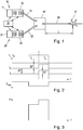
- Fig. 1 shows a transmitter for testing discontinuities in lines.
- Fig. 2 shows the sequence of frequencies for creating the pulse that is used to detect discontinuities.
- Fig. 3 shows the time course of the power of a pulse used for detection.
- Figures 4 and 5 show individual frequency components in the emitted and received laser light.
- Figure 5a shows a possible control of an electro-absorption modulator with an electrical frequency duplexer.
- Fig. 6 shows schematically the time course of the signal received by means of an electro-absorption modulator between the sending of the pulse and the detection of the reflection of the pulse at a discontinuity.
- Fig. 7 shows an alternative device that allows switching between a data transmission mode and a discontinuity detection mode.
- a time-of-flight measurement is typically used which is based on the fact that in the area of optical discontinuities 51 the light transmitted by the lasers is at least partially reflected on them.
- two laser units 10, 20 are used, which are connected to one another via a polarization beam splitter 40 and beam laser light with two different polarization directions into the optical channel to be examined.
- Fig. 1 the two laser units 10, 20 are shown, each having a laser 11, 21 and an electro-absorption modulator 12, 22 located in the beam path of the laser 11, 21.
- optical connections of the two electro-absorption modulators 12, 22 are connected to the two inputs 41, 42 of the polarization beam splitter 40 via optical connecting lines 13, 23.
- the output 43 of the polarization beam splitter 40 is connected to the optical channel 50.
- a test pulse is then generated by means of the two laser units 10, 20.
- the two laser units 10, 20 are controlled by a control unit 30, the control unit 30 specifying a laser current for each of the two lasers 11, 21 via which the respective laser frequencies f 1 , f 2 can be set.
- the laser frequencies f 1 , f 2 can also be set and stabilized by means of a temperature controller, whereby the setting of the frequencies is possible in a wider range.
- a temperature controller such a regulation of the temperature can also be used in order to exclude environmental influences which, for example, result from the drift of the room temperature.
- the light from the lasers 11, 21 is then at least partially reflected at the discontinuities 51.
- This circumstance can be determined by means of the electro-absorption modulators 12, 22, which have the advantageous property that they not only allow their light transmission to be regulated by impressing a signal on their electrical connection, but also provide a voltage at their electrical connection when light from meets the electro-absorption modulator on the outside.
- the light reflected at the discontinuity 51 and the laser light do not have exactly the same frequency, but rather differ from one another by a predetermined frequency value which is between 1 and 10 GHz.
- a predetermined frequency value which is between 1 and 10 GHz.
- an electrical signal is created, the frequency of which corresponds to the difference frequency of the two lasers 11, 21. If the same optical frequency were used for sending and receiving, the Electro-absorption modulator 12, 22 generated superimposition signal have a very low frequency, in particular have the frequency zero, whereby a very high electrical noise would be present overall.
- a modulation signal in the range of this difference frequency - also referred to as intermediate frequency - is generated at the electrical connection of the electro-absorption modulator 12, 22, which does not cause the noise interference described above is subject and can also be conditioned in a simple manner in the electronic field.
- the concrete creation of the test pulse T is detailed in Fig. 2 shown in more detail.
- the two lasers 11, 21 each emit light with a reference frequency f 1 , f 2 , the two reference frequencies f 1 , f 2 having a predetermined reference frequency difference ⁇ f from one another.
- This reference frequency difference ⁇ f can typically be set electrically, for example via a central control unit 30, and is in the range between 1 GHz and 10 GHz.
- V eam specified by the control unit 30 at the electrical connection of the two electro- absorption modulators 12, 22, this is shown in addition to the respective laser current of the laser 11, 21.
- the test pulse T is, as in Fig. 2 shown, divided into two equally long periods of time T 1 , T 2 .
- the duration of the test pulse is typically 1 to 10 ns. At a speed of light of about 2.10 8 m / s in the optical channel, this pulse length allows a spatial resolution of the reflected signals of about 20 cm to 2 m.
- the frequencies of the lasers 11, 21 are reset to the reference frequencies f 1 , f 2 .
- the voltage at the electrical connection of the two electroabsorption modulators 12, 22 is reset to a value at which the two electroabsorption modulators 12, 22 are no longer transparent to the laser light.
- the two lasers 11, 21 are operated with their respective reference frequencies f 1 , f 2 .
- the control unit 30 modifies the laser current of the respective lasers 11, 21 by a predetermined detuning frequency difference ⁇ f, in the present case it is increased.
- the temporal arrangement of the two time periods can also be interchanged, ie it is also possible that the second time period T 2 , in which the laser frequencies are detuned or modified, precedes the first time period T 1.
- the light output at the output of the two laser units 10, 20 corresponds approximately to that in FIG Fig. 3 shown temporal course.
- the transit time behavior of the light by measuring the reflected light in the area of the laser units 10, 20 it can be determined at which point in the optical channel 50 optical discontinuities 51 may be present.
- a major problem with this measurement is that due to the unpredictable polarization rotation in the optical channels 50, as occurs in particular in fiber optic lines, optical pulses generated by a laser 11, 21 with a predetermined reference frequency, which with a first polarization in an optical channel 50, are rotated in this optical channel 50 with regard to their polarization in an unpredictable manner and, in the worst case, are then transmitted to the respective other laser unit 10, 20 due to the polarization beam splitter 40.
- the two lasers 11, 21 each have different optical reference frequencies f 1 , f 2 that differ from one another by between 1 and 10 GHz, the reflected signal from the electro-absorption modulator 12, 22 cannot be received or cannot be received in the correct frequency range.
- the portion of the pulse T originating from the first laser 11 is transmitted back to the first modulated laser 10, and the portion originating from the second modulated laser 20 of the pulse is sent to the second modulated laser 20 transmitted back and superimposed in the relevant electro-absorption modulator 12, 22 with the laser light of the respective laser 11, 12, the frequency of which was reset to the reference frequency f 1 , f 2 after the pulse was emitted.
- the temporally first part of the pulse T which was generated during the time period T 1 , corresponds in terms of its frequency to the reference frequency f 1 , f 2 of the respective laser, so that an overlay signal in the low-frequency range is obtained at the output of the electro-absorption modulator 12, 22, which is subject to strong noise-related interference and cannot be further evaluated.
- the light generated during the second time period T 2 of the pulse T is offset by the detuning frequency difference ⁇ f compared to the light of the respective laser 11, 21, which was reset to the reference frequency f 1 , f 2 after the pulse T was generated electrical connection of the electro-absorption modulator 12, 22 to a voltage signal in the range of the frequency ⁇ f predetermined by the detuning frequency difference. This signal is not subject to interference caused by low frequencies and can easily be further processed electrically.
- the light generated by the first laser unit 10 reaches the second laser unit 20 and the light generated by the second laser unit 20 in each case with the first laser 10.
- the signals generated during the first time period with the reference frequency f 1 , f 2 are each generated with the reference frequency f 1 , f 2 of the laser of the respective other modulated laser 11, 21 is superimposed so that there is a frequency difference in the range of the reference frequency difference ⁇ f between the respective laser frequency f 1 , f 2 and the frequency of the reflected light. Since this reference frequency difference ⁇ f is in the range from 1 GHz to 10 GHz, it can advantageously be tapped at the electrical connection of the electro-absorption modulator 12, 22 of the respective laser unit 10, 20.
- the light of the pulse T which was generated during the second time period T 2 , can also be detected.
- the frequency of this signal may be too small to be detected without noise. Overall, these signal components can be neglected.
- the signal emitted by the second laser f 2 with a frequency f 2 + ⁇ f is superimposed on the first electro-absorption modulator 12 with the light produced by the first laser 11 with a frequency f 1.
- a signal in the range of an intermediate frequency of ⁇ f - / + ⁇ f can be detected on the electroabsorption modulator.
- the signal applied to the electrical connection of the electro-absorption modulator 12, 22 is shown in FIG Figures 4 and 5 shown at different times.
- Fig. 4 the frequency profile of the electrical signal at the input of the electro-absorption modulator 12, 22 at the time the pulse is generated. It can be seen here that the electroabsorption modulator 12, 22 is switched to be permeable for the generation of the pulse T due to an external excitation, so that the pulse T can be emitted via the optical channel 50.
- Fig. 5 the signal spectrum obtained on the basis of the received reflected pulse at the electrical connection of the electroabsorption modulator 12, 22 or several possible signal spectra in this regard is shown.
- the transmission signal is shown in dashed lines to illustrate the frequency difference to the transmission signal. It can be seen that due to the superimposition of the reflected portion of the pulse with the respective light of the laser 11, 21 signals in the range of the intermediate frequency are received, which are either in the range of the reference frequency difference ⁇ f or the detuning frequency difference ⁇ f.
- the common connection 31c, ie the common frequency connection, of a frequency duplexer 31 can be connected to the electrical connection of the electroabsorption modulators 12, 22 ( Figure 5a ).
- the low-frequency connection 31e of the frequency duplexer 31 is connected to a pulse generator 33 which generates the pulse T and which belongs to the control unit 30 and is controlled by it.
- the high-frequency connection 31h of the frequency duplexer 31 is connected to an evaluation unit 32 belonging to the control unit 30. Alternatively, the high-frequency Terminal 31h can be used directly for further processing of the reflected signal.
- the crossover frequency f T of the frequency duplexer can advantageously be selected in the intermediate range between the spectral components of the test pulse and the minimum of reference frequency difference ⁇ f and detuning frequency difference ⁇ f.
- a test pulse duration of 10 ns was selected so that the frequency components emanating from the test pulse are below a frequency of 0.2 GHz. Since both the reference frequency difference ⁇ f and the detuning frequency difference ⁇ f are in the range of 10 GHz, a crossover frequency of the frequency multiplexer can be set at around 0.5 GHz.
- Fig. 6 the time course of the light prevailing in the electroabsorption modulator 12, 22 is shown schematically.
- the light is received at a different point in time after the pulse T is emitted. Since the sensitivity of the pulse T is relevant at different times depending on the polarization rotation, the accuracy of the measurement is limited by the duration of the pulse T. If the speed of light in the optical channel 50 is 2.10 8 m / s and the pulse length is 10 ns, the result is a resolution accuracy of 200 cm.
- the distance between the laser units 10, 20 and the discontinuity 51 can be deduced, taking into account the resolution accuracy.
- a particularly preferred embodiment of the invention is in Fig. 7 shown in more detail.
- Two different control units 30, 60 are provided, with the control unit 30 corresponding to the control unit 30 described in connection with the previous exemplary embodiment and the other control unit functioning as a transmission control unit 60, which is designed to supply the electro-absorption modulators 12, 22 for outputting data transmission signals cause and detect received signals at the electrical connection of the electroabsorption modulator 12, 22.
- this transmission control unit 60 is also designed to modify the laser current of the two lasers 11, 21 if this should be necessary for the data transmission.
- Both the control unit 30 and the transmission control unit 60 thus have a control connection for controlling the laser current, as well as an output for connection to the electrical connection of the electro-absorption modulator 12, 22.
- the respective connections of the control unit 30 or the transmission control unit 60 are forwarded to a switching unit 70, which makes it possible to connect either the control unit 30 or the transmission control unit 60 to the two laser units 10, 20 in order to alternate between the two functions in any cycle ratio without changing the opto -electronic hardware to run.
- the transmission control unit 60 may typically be connected to a digital computer, telephone, antenna, or similar device.
Landscapes
- Physics & Mathematics (AREA)
- Chemical & Material Sciences (AREA)
- Analytical Chemistry (AREA)
- General Physics & Mathematics (AREA)
- Optics & Photonics (AREA)
- Engineering & Computer Science (AREA)
- Electromagnetism (AREA)
- Computer Networks & Wireless Communication (AREA)
- Signal Processing (AREA)
- Microelectronics & Electronic Packaging (AREA)
- Optical Communication System (AREA)
Claims (5)
- Procédé de détection de discontinuités (51) dans un canal optique (50), en particulier dans une conduite en fibre de verre,- avec deux unités laser (10, 20), comprenant respectivement un laser (11, 21) et un modulateur à électroabsorption (12, 22),- dans lequel les fréquences de référence (f1, f2) des deux lasers (11, 21) présentent une différence de fréquence de référence prédéterminée (δf), en particulier dans une plage de 1 GHz à 10 GHz,- dans lequel les connexions optiques (120, 12p ; 220, 22p) du modulateur à électroabsorption (12, 22) sont acheminés aux deux entrées (41,42) d'un diviseur de faisceau à polarisation (40) et la sortie (43) du diviseur de faisceau à polarisation (40) est connectée au canal optique (50),- dans lequel une impulsion d'essai (T), en particulier d'une durée de 1 à 10 ns, est appliquée simultanément aux deux modulateurs à électroabsorption (12, 22) et ainsi, de la lumière laser est transmise par les lasers (11, 21) à travers les modulateurs à électroabsorption respectifs (12, 22) pendant le temps de l'impulsion d'essai (T),- dans lequel l'impulsion d'essai (T) est divisée en deux périodes de temps (T1, T2), en particulier de même durée, et pendant la première période de temps (T1), les lasers (11, 21) sont exploités à leur fréquence de référence respective (f1, f2), et pendant la seconde période de temps (T2), les fréquences d'émission des lasers sont désaccordées par rapport aux fréquences de référence, en particulier par modification du courant laser respectif, de préférence par une fréquence de 1 à 10 GHz, selon une différence de fréquence de désaccord prédéterminée (Δf),- dans lequel les deux modulateurs à électroabsorption (12, 22) sont déplacés dans un état opaque après la fin de l'impulsion d'essai (T), dans lequel les modulateurs à électroabsorption (12, 22) sont éclairés d'un côté par les lasers (11, 21) à leur fréquence de référence respective (f1, f2) et absorbent simultanément la lumière de l'impulsion d'essai (T) réfléchie au niveau d'une discontinuité (51) via le canal optique (50), et- dans lequel les deux modulateurs à électroabsorption (12, 22) mettent à disposition, au niveau de leur connexion optique (120, 12p ; 220, 22p), un courant photoélectrique correspondant à l'ensemble de la lumière incidente sur ceux-ci, et les courants photoélectriques ainsi déterminés, le cas échéant après processus de filtrage et/ou d'amplification, sont considérés comme caractéristiques pour le canal respectif.
- Dispositif de détection de discontinuités (51) dans un canal optique (50), en particulier une conduite en fibre de verre,- avec deux unités laser (10, 20), comprenant respectivement un laser (11, 21) et un modulateur à électroabsorption (12, 22),- dans lequel les fréquences de référence (f1, f2) des deux lasers (11, 21) présentent une différence de fréquence de référence prédéterminée (δf), en particulier dans une plage de 1 GHz à 10 GHz,- dans lequel les connexions optiques (120, 12p ; 22o, 22p) des modulateurs à électroabsorption (12, 22) sont acheminés aux deux entrées (41,42) d'un diviseur de faisceau à polarisation (40) et la sortie (43) du diviseur de faisceau à polarisation est connectée au canal optique (50),- dans lequel le dispositif comprend une unité de commande (30), l'unité de commande (30) comprenant un générateur d'impulsions, qui est réalisé pour générer une impulsion d'essai au niveau des connexions électriques (12e ; 22e) des deux modulateurs à électroabsorption (12, 22) et pour appliquer simultanément une impulsion d'essai, en particulier d'une durée de 1 à 10 ns, dans lequel l'unité de commande (30) est réalisée de manière à commander le courant laser des deux lasers (11, 21) pendant l'émission de l'impulsion d'essai (T) de sorte que pendant une première période de temps (T1), les lasers (11, 21) sont exploités à leur fréquence de référence respective (f1, f2) et, pendant une seconde période de temps (T2), en particulier de même durée et/ou suivant ou précédant immédiatement la première période de temps (T1), les fréquences des lasers (11, 21) sont désaccordées par rapport aux fréquences de référence (f1, f2), de préférence par une fréquence de 1 à 10 GHz, selon une différence de fréquence de désaccord prédéterminée (Δf), et- dans lequel l'unité de commande (30) est réalisée pour continuer à exploiter les lasers (11, 21) à leurs fréquences de référence (f1, f2) après la fin de l'impulsion d'essai et pour déplacer les deux modulateurs à électroabsorption (12, 22) dans un état d'absorption dans lequel les modulateurs à électroabsorption (12, 22) absorbent à la fois la lumière laser des deux lasers (11, 21) et la lumière réfléchie par le canal optique (50) et mettent à disposition, au niveau de la connexion électrique, un courant photoélectrique correspondant à l'ensemble de la lumière incidente sur ceux-ci,- dans lequel l'unité de commande (30) est réalisée pour surveiller les connexions électriques (12e ; 22e) des deux modulateurs à électroabsorption (12, 22) après la fin de l'impulsion d'essai (T).
- Dispositif selon la revendication 2,- dans lequel la connexion commune (31c) d'un duplexeur de fréquence (31) est connectée à la connexion électrique d'au moins un des modulateurs à électroabsorption (12, 22),- dans lequel la connexion basse fréquence (311) du duplexeur de fréquence (31) est connectée à un générateur d'impulsions (33) générant l'impulsion d'essai (T), et- dans lequel la connexion haute fréquence (31h) du duplexeur de fréquence (31) est connectée à une unité d'évaluation (32) ou le signal caractéristique est appliqué de manière préparée à la connexion haute fréquence (31h).
- Dispositif selon la revendication 3, dans lequel la fréquence de coupure du duplexeur de fréquence est choisie entre les composantes spectrales de l'impulsion d'essai (T) et le minimum de la différence de fréquence de référence (δf) et de la différence de fréquence de désaccord (Δf).
- Dispositif selon l'une quelconque des revendications 2 à 4, dans lequel une unité de commande de transmission (60) est en outre prévue, laquelle est réalisée pour amener les unités laser (10, 20) à transmettre des données ainsi qu'à recevoir des données et, dans lequel l'unité de commande de transmission (60) est de préférence reliée à un autre réseau pour la transmission de données, et
dans lequel une unité de commutation (70) est prévue, laquelle est réalisée pour permettre l'activation des unités laser (10, 20) par l'unité de commande (30) ou par l'unité de commande de transmission (60).
Applications Claiming Priority (1)
| Application Number | Priority Date | Filing Date | Title |
|---|---|---|---|
| ATA50847/2018A AT521463B1 (de) | 2018-10-03 | 2018-10-03 | Verfahren zur Detektion von Diskontinuitäten in einem optischen Kanal, insbesondere bei einer Glasfaserleitung |
Publications (2)
| Publication Number | Publication Date |
|---|---|
| EP3633877A1 EP3633877A1 (fr) | 2020-04-08 |
| EP3633877B1 true EP3633877B1 (fr) | 2021-03-24 |
Family
ID=68109258
Family Applications (1)
| Application Number | Title | Priority Date | Filing Date |
|---|---|---|---|
| EP19200901.7A Not-in-force EP3633877B1 (fr) | 2018-10-03 | 2019-10-01 | Procédé de détection des discontinuités dans un canal optique, en particulier dans une conduite en fibre de verre |
Country Status (3)
| Country | Link |
|---|---|
| US (1) | US10928273B2 (fr) |
| EP (1) | EP3633877B1 (fr) |
| AT (1) | AT521463B1 (fr) |
Families Citing this family (4)
| Publication number | Priority date | Publication date | Assignee | Title |
|---|---|---|---|---|
| WO2022073195A1 (fr) | 2020-10-09 | 2022-04-14 | Huawei Technologies Co., Ltd. | Appareils et procédés de génération d'un signal optique dans un réseau de communication optique |
| US20220247488A1 (en) * | 2021-02-02 | 2022-08-04 | Huawei Technologies Co., Ltd. | Method and system inspecting fibered optical communication paths |
| CN115603816B (zh) * | 2022-09-09 | 2025-07-11 | 中国科学院国家授时中心 | 一种光纤光频传递系统及方法 |
| CN116131940B (zh) * | 2023-04-17 | 2023-07-07 | 广州赛宝计量检测中心服务有限公司 | 光不连续性测试仪校准装置、系统及方法 |
Family Cites Families (12)
| Publication number | Priority date | Publication date | Assignee | Title |
|---|---|---|---|---|
| JP2589345B2 (ja) * | 1988-06-24 | 1997-03-12 | 日本電信電話株式会社 | 光ファイバの特性評価方法および装置 |
| US5394260A (en) * | 1992-02-03 | 1995-02-28 | Kokusai Denshin Denwa Kabushiki Kaisha | Optical pulse generator |
| DE19641441A1 (de) * | 1996-10-08 | 1998-04-09 | Siemens Ag | Verfahren sowie Vorrichtung zur Dispersionsmessung |
| GB2404992B (en) * | 2003-08-12 | 2006-12-27 | Agilent Technologies Inc | Electro-absorption modulation of optical signals |
| JP5380647B2 (ja) * | 2007-05-25 | 2014-01-08 | アンリツ株式会社 | 光信号サンプリング装置及びその方法並びにそれを用いる光信号モニタ装置及びその方法 |
| JP5495506B2 (ja) * | 2008-05-13 | 2014-05-21 | キヤノン株式会社 | レーザ装置および光断層画像撮像装置 |
| WO2010061718A1 (fr) * | 2008-11-27 | 2010-06-03 | ニューブレクス株式会社 | Détecteur à fibres optiques distribué |
| US9281893B2 (en) * | 2013-10-23 | 2016-03-08 | Lumentum Operations Llc | In-service monitoring of a fiberoptic network |
| JP6199341B2 (ja) * | 2015-06-11 | 2017-09-20 | アンリツ株式会社 | サンプリング回路およびサンプリング方法とサンプリングオシロスコープ並びに波形表示方法 |
| CN104980225B (zh) * | 2015-07-24 | 2017-10-03 | 武汉光迅科技股份有限公司 | 一种基于幅度调制的带内透传监控信号的光模块 |
| EP3312582B1 (fr) | 2016-10-20 | 2020-02-26 | Xieon Networks S.à r.l. | Réflectomètre optique temporel à l'aide d'un modulateur à électro-absorption à la fois pour la formation d'impulsions et la détection d'impulsions |
| US10673528B1 (en) * | 2019-02-25 | 2020-06-02 | Huawei Technologies Co., Ltd. | Methods and apparatuses for controlling optical signals in optical networks |
-
2018
- 2018-10-03 AT ATA50847/2018A patent/AT521463B1/de not_active IP Right Cessation
-
2019
- 2019-10-01 EP EP19200901.7A patent/EP3633877B1/fr not_active Not-in-force
- 2019-10-03 US US16/592,098 patent/US10928273B2/en not_active Expired - Fee Related
Non-Patent Citations (1)
| Title |
|---|
| None * |
Also Published As
| Publication number | Publication date |
|---|---|
| US20200110003A1 (en) | 2020-04-09 |
| AT521463A4 (de) | 2020-02-15 |
| EP3633877A1 (fr) | 2020-04-08 |
| US10928273B2 (en) | 2021-02-23 |
| AT521463B1 (de) | 2020-02-15 |
Similar Documents
| Publication | Publication Date | Title |
|---|---|---|
| EP3633877B1 (fr) | Procédé de détection des discontinuités dans un canal optique, en particulier dans une conduite en fibre de verre | |
| DE69519990T2 (de) | Fehlerortung in optischen übertragungssystemen | |
| DE68920047T2 (de) | Geräuschmessung für eine faseroptische verbindung und optimierungssystem. | |
| DE69108232T2 (de) | Erkennung von verlusten in optischen fasern. | |
| DE69521443T2 (de) | System, verfahren und vorrichtung zur überwachung eines faseroptischen kabels | |
| DE102012208308A1 (de) | Optisches Entfernungsmessgerät mit Kalibriereinrichtung zum Berücksichtigen von Übersprechen | |
| DE102007059551A1 (de) | Einrichtung zur Messung der Eigenschaften einer Lichtleitfaser | |
| DE10218421A1 (de) | Vorrichtung zur Messung der Eigenschaften von Lichtwellenleitern | |
| EP0054292A2 (fr) | Arrangement de mesure fibre-optique | |
| EP1796295B1 (fr) | Procédé destiné à la détection et à la localisation de perturbations sur un trajet de transmission optique et un système de transmission optique | |
| DE69823609T2 (de) | Überwachung der optischen Signalleistung mit einem Signaturbitmuster in WDM Systemen | |
| DE602005004787T2 (de) | Optisches Sender- Empfänger-Modul zur Überwachung einer optischen Faser und Verfahren zum Bereitstellen der Überwachungsdaten der optischen Faser | |
| EP1095472A1 (fr) | Procede et dispositif pour effectuer des mesures de controle et de surveillance sur des lignes de transmission optique | |
| EP4057026B1 (fr) | Mesure de distance au moyen d'un système de capteur optique actif | |
| DE60127060T2 (de) | Messung der polarisationsabhängigen Eigenschaft optischer Einheiten | |
| DE102009046691B4 (de) | Sensorvorrichtung | |
| EP0602075B1 (fr) | Detecteur optique pour mouvements de rotation | |
| EP1224754B1 (fr) | Procede et dispositif destines a la surveillance continue d'une liaison de transmission optique | |
| EP0675351A2 (fr) | Procédé de détermination dans un fibre optique la longeur d'ondes pour laquelle il y n'a pas de dispersion | |
| DE60211126T2 (de) | Teststruktur zur gleichzeitigen Charakterisierung von zwei Ports einer optischen Komponente mittels interferometerbasierender optischer Netzwerkanalyse | |
| EP3521859A1 (fr) | Capteur photoélectrique trigonométrique | |
| DE69520008T2 (de) | Vorrichtung zum Abfragen eines Lichtwellenleiternetzwerks | |
| EP3208636A1 (fr) | Capteur optoélectronique et procédé destiné à la saisie d'objets | |
| DE602004003968T2 (de) | Optischer Empfänger und Verfahren zur Kompensation der chromatischen Dispersion | |
| DE69829799T2 (de) | Messung der Augenöffnung von optischen Signalen mittels optischen Abtasten |
Legal Events
| Date | Code | Title | Description |
|---|---|---|---|
| PUAI | Public reference made under article 153(3) epc to a published international application that has entered the european phase |
Free format text: ORIGINAL CODE: 0009012 |
|
| STAA | Information on the status of an ep patent application or granted ep patent |
Free format text: STATUS: THE APPLICATION HAS BEEN PUBLISHED |
|
| AK | Designated contracting states |
Kind code of ref document: A1 Designated state(s): AL AT BE BG CH CY CZ DE DK EE ES FI FR GB GR HR HU IE IS IT LI LT LU LV MC MK MT NL NO PL PT RO RS SE SI SK SM TR |
|
| AX | Request for extension of the european patent |
Extension state: BA ME |
|
| STAA | Information on the status of an ep patent application or granted ep patent |
Free format text: STATUS: REQUEST FOR EXAMINATION WAS MADE |
|
| 17P | Request for examination filed |
Effective date: 20200915 |
|
| RBV | Designated contracting states (corrected) |
Designated state(s): AL AT BE BG CH CY CZ DE DK EE ES FI FR GB GR HR HU IE IS IT LI LT LU LV MC MK MT NL NO PL PT RO RS SE SI SK SM TR |
|
| GRAP | Despatch of communication of intention to grant a patent |
Free format text: ORIGINAL CODE: EPIDOSNIGR1 |
|
| STAA | Information on the status of an ep patent application or granted ep patent |
Free format text: STATUS: GRANT OF PATENT IS INTENDED |
|
| RIC1 | Information provided on ipc code assigned before grant |
Ipc: G01M 11/08 20060101ALI20201012BHEP Ipc: G01M 11/00 20060101ALI20201012BHEP Ipc: H04B 10/071 20130101AFI20201012BHEP |
|
| INTG | Intention to grant announced |
Effective date: 20201118 |
|
| GRAS | Grant fee paid |
Free format text: ORIGINAL CODE: EPIDOSNIGR3 |
|
| GRAA | (expected) grant |
Free format text: ORIGINAL CODE: 0009210 |
|
| STAA | Information on the status of an ep patent application or granted ep patent |
Free format text: STATUS: THE PATENT HAS BEEN GRANTED |
|
| AK | Designated contracting states |
Kind code of ref document: B1 Designated state(s): AL AT BE BG CH CY CZ DE DK EE ES FI FR GB GR HR HU IE IS IT LI LT LU LV MC MK MT NL NO PL PT RO RS SE SI SK SM TR |
|
| REG | Reference to a national code |
Ref country code: GB Ref legal event code: FG4D Free format text: NOT ENGLISH |
|
| REG | Reference to a national code |
Ref country code: CH Ref legal event code: EP |
|
| REG | Reference to a national code |
Ref country code: DE Ref legal event code: R096 Ref document number: 502019001055 Country of ref document: DE |
|
| REG | Reference to a national code |
Ref country code: IE Ref legal event code: FG4D Free format text: LANGUAGE OF EP DOCUMENT: GERMAN |
|
| REG | Reference to a national code |
Ref country code: AT Ref legal event code: REF Ref document number: 1375570 Country of ref document: AT Kind code of ref document: T Effective date: 20210415 |
|
| REG | Reference to a national code |
Ref country code: LT Ref legal event code: MG9D |
|
| PG25 | Lapsed in a contracting state [announced via postgrant information from national office to epo] |
Ref country code: HR Free format text: LAPSE BECAUSE OF FAILURE TO SUBMIT A TRANSLATION OF THE DESCRIPTION OR TO PAY THE FEE WITHIN THE PRESCRIBED TIME-LIMIT Effective date: 20210324 Ref country code: BG Free format text: LAPSE BECAUSE OF FAILURE TO SUBMIT A TRANSLATION OF THE DESCRIPTION OR TO PAY THE FEE WITHIN THE PRESCRIBED TIME-LIMIT Effective date: 20210624 Ref country code: GR Free format text: LAPSE BECAUSE OF FAILURE TO SUBMIT A TRANSLATION OF THE DESCRIPTION OR TO PAY THE FEE WITHIN THE PRESCRIBED TIME-LIMIT Effective date: 20210625 Ref country code: FI Free format text: LAPSE BECAUSE OF FAILURE TO SUBMIT A TRANSLATION OF THE DESCRIPTION OR TO PAY THE FEE WITHIN THE PRESCRIBED TIME-LIMIT Effective date: 20210324 Ref country code: NO Free format text: LAPSE BECAUSE OF FAILURE TO SUBMIT A TRANSLATION OF THE DESCRIPTION OR TO PAY THE FEE WITHIN THE PRESCRIBED TIME-LIMIT Effective date: 20210624 |
|
| PG25 | Lapsed in a contracting state [announced via postgrant information from national office to epo] |
Ref country code: SE Free format text: LAPSE BECAUSE OF FAILURE TO SUBMIT A TRANSLATION OF THE DESCRIPTION OR TO PAY THE FEE WITHIN THE PRESCRIBED TIME-LIMIT Effective date: 20210324 Ref country code: RS Free format text: LAPSE BECAUSE OF FAILURE TO SUBMIT A TRANSLATION OF THE DESCRIPTION OR TO PAY THE FEE WITHIN THE PRESCRIBED TIME-LIMIT Effective date: 20210324 Ref country code: LV Free format text: LAPSE BECAUSE OF FAILURE TO SUBMIT A TRANSLATION OF THE DESCRIPTION OR TO PAY THE FEE WITHIN THE PRESCRIBED TIME-LIMIT Effective date: 20210324 |
|
| REG | Reference to a national code |
Ref country code: NL Ref legal event code: MP Effective date: 20210324 |
|
| PG25 | Lapsed in a contracting state [announced via postgrant information from national office to epo] |
Ref country code: NL Free format text: LAPSE BECAUSE OF FAILURE TO SUBMIT A TRANSLATION OF THE DESCRIPTION OR TO PAY THE FEE WITHIN THE PRESCRIBED TIME-LIMIT Effective date: 20210324 |
|
| PG25 | Lapsed in a contracting state [announced via postgrant information from national office to epo] |
Ref country code: SM Free format text: LAPSE BECAUSE OF FAILURE TO SUBMIT A TRANSLATION OF THE DESCRIPTION OR TO PAY THE FEE WITHIN THE PRESCRIBED TIME-LIMIT Effective date: 20210324 Ref country code: EE Free format text: LAPSE BECAUSE OF FAILURE TO SUBMIT A TRANSLATION OF THE DESCRIPTION OR TO PAY THE FEE WITHIN THE PRESCRIBED TIME-LIMIT Effective date: 20210324 Ref country code: CZ Free format text: LAPSE BECAUSE OF FAILURE TO SUBMIT A TRANSLATION OF THE DESCRIPTION OR TO PAY THE FEE WITHIN THE PRESCRIBED TIME-LIMIT Effective date: 20210324 Ref country code: LT Free format text: LAPSE BECAUSE OF FAILURE TO SUBMIT A TRANSLATION OF THE DESCRIPTION OR TO PAY THE FEE WITHIN THE PRESCRIBED TIME-LIMIT Effective date: 20210324 |
|
| PG25 | Lapsed in a contracting state [announced via postgrant information from national office to epo] |
Ref country code: IS Free format text: LAPSE BECAUSE OF FAILURE TO SUBMIT A TRANSLATION OF THE DESCRIPTION OR TO PAY THE FEE WITHIN THE PRESCRIBED TIME-LIMIT Effective date: 20210724 Ref country code: PL Free format text: LAPSE BECAUSE OF FAILURE TO SUBMIT A TRANSLATION OF THE DESCRIPTION OR TO PAY THE FEE WITHIN THE PRESCRIBED TIME-LIMIT Effective date: 20210324 Ref country code: SK Free format text: LAPSE BECAUSE OF FAILURE TO SUBMIT A TRANSLATION OF THE DESCRIPTION OR TO PAY THE FEE WITHIN THE PRESCRIBED TIME-LIMIT Effective date: 20210324 Ref country code: PT Free format text: LAPSE BECAUSE OF FAILURE TO SUBMIT A TRANSLATION OF THE DESCRIPTION OR TO PAY THE FEE WITHIN THE PRESCRIBED TIME-LIMIT Effective date: 20210726 Ref country code: RO Free format text: LAPSE BECAUSE OF FAILURE TO SUBMIT A TRANSLATION OF THE DESCRIPTION OR TO PAY THE FEE WITHIN THE PRESCRIBED TIME-LIMIT Effective date: 20210324 |
|
| REG | Reference to a national code |
Ref country code: DE Ref legal event code: R097 Ref document number: 502019001055 Country of ref document: DE |
|
| PG25 | Lapsed in a contracting state [announced via postgrant information from national office to epo] |
Ref country code: AL Free format text: LAPSE BECAUSE OF FAILURE TO SUBMIT A TRANSLATION OF THE DESCRIPTION OR TO PAY THE FEE WITHIN THE PRESCRIBED TIME-LIMIT Effective date: 20210324 Ref country code: DK Free format text: LAPSE BECAUSE OF FAILURE TO SUBMIT A TRANSLATION OF THE DESCRIPTION OR TO PAY THE FEE WITHIN THE PRESCRIBED TIME-LIMIT Effective date: 20210324 Ref country code: ES Free format text: LAPSE BECAUSE OF FAILURE TO SUBMIT A TRANSLATION OF THE DESCRIPTION OR TO PAY THE FEE WITHIN THE PRESCRIBED TIME-LIMIT Effective date: 20210324 |
|
| PLBE | No opposition filed within time limit |
Free format text: ORIGINAL CODE: 0009261 |
|
| STAA | Information on the status of an ep patent application or granted ep patent |
Free format text: STATUS: NO OPPOSITION FILED WITHIN TIME LIMIT |
|
| PG25 | Lapsed in a contracting state [announced via postgrant information from national office to epo] |
Ref country code: SI Free format text: LAPSE BECAUSE OF FAILURE TO SUBMIT A TRANSLATION OF THE DESCRIPTION OR TO PAY THE FEE WITHIN THE PRESCRIBED TIME-LIMIT Effective date: 20210324 |
|
| 26N | No opposition filed |
Effective date: 20220104 |
|
| PG25 | Lapsed in a contracting state [announced via postgrant information from national office to epo] |
Ref country code: IS Free format text: LAPSE BECAUSE OF FAILURE TO SUBMIT A TRANSLATION OF THE DESCRIPTION OR TO PAY THE FEE WITHIN THE PRESCRIBED TIME-LIMIT Effective date: 20210724 |
|
| REG | Reference to a national code |
Ref country code: BE Ref legal event code: MM Effective date: 20211031 |
|
| PG25 | Lapsed in a contracting state [announced via postgrant information from national office to epo] |
Ref country code: MC Free format text: LAPSE BECAUSE OF FAILURE TO SUBMIT A TRANSLATION OF THE DESCRIPTION OR TO PAY THE FEE WITHIN THE PRESCRIBED TIME-LIMIT Effective date: 20210324 |
|
| PG25 | Lapsed in a contracting state [announced via postgrant information from national office to epo] |
Ref country code: LU Free format text: LAPSE BECAUSE OF NON-PAYMENT OF DUE FEES Effective date: 20211001 Ref country code: BE Free format text: LAPSE BECAUSE OF NON-PAYMENT OF DUE FEES Effective date: 20211031 |
|
| PG25 | Lapsed in a contracting state [announced via postgrant information from national office to epo] |
Ref country code: FR Free format text: LAPSE BECAUSE OF NON-PAYMENT OF DUE FEES Effective date: 20211031 |
|
| PG25 | Lapsed in a contracting state [announced via postgrant information from national office to epo] |
Ref country code: IE Free format text: LAPSE BECAUSE OF NON-PAYMENT OF DUE FEES Effective date: 20211001 |
|
| PG25 | Lapsed in a contracting state [announced via postgrant information from national office to epo] |
Ref country code: IT Free format text: LAPSE BECAUSE OF FAILURE TO SUBMIT A TRANSLATION OF THE DESCRIPTION OR TO PAY THE FEE WITHIN THE PRESCRIBED TIME-LIMIT Effective date: 20210324 |
|
| PGFP | Annual fee paid to national office [announced via postgrant information from national office to epo] |
Ref country code: DE Payment date: 20221019 Year of fee payment: 4 |
|
| REG | Reference to a national code |
Ref country code: CH Ref legal event code: PL |
|
| PG25 | Lapsed in a contracting state [announced via postgrant information from national office to epo] |
Ref country code: CY Free format text: LAPSE BECAUSE OF FAILURE TO SUBMIT A TRANSLATION OF THE DESCRIPTION OR TO PAY THE FEE WITHIN THE PRESCRIBED TIME-LIMIT Effective date: 20210324 |
|
| PG25 | Lapsed in a contracting state [announced via postgrant information from national office to epo] |
Ref country code: LI Free format text: LAPSE BECAUSE OF NON-PAYMENT OF DUE FEES Effective date: 20221031 Ref country code: HU Free format text: LAPSE BECAUSE OF FAILURE TO SUBMIT A TRANSLATION OF THE DESCRIPTION OR TO PAY THE FEE WITHIN THE PRESCRIBED TIME-LIMIT; INVALID AB INITIO Effective date: 20191001 Ref country code: CH Free format text: LAPSE BECAUSE OF NON-PAYMENT OF DUE FEES Effective date: 20221031 |
|
| PG25 | Lapsed in a contracting state [announced via postgrant information from national office to epo] |
Ref country code: MK Free format text: LAPSE BECAUSE OF FAILURE TO SUBMIT A TRANSLATION OF THE DESCRIPTION OR TO PAY THE FEE WITHIN THE PRESCRIBED TIME-LIMIT Effective date: 20210324 |
|
| REG | Reference to a national code |
Ref country code: DE Ref legal event code: R119 Ref document number: 502019001055 Country of ref document: DE |
|
| GBPC | Gb: european patent ceased through non-payment of renewal fee |
Effective date: 20231001 |
|
| PG25 | Lapsed in a contracting state [announced via postgrant information from national office to epo] |
Ref country code: GB Free format text: LAPSE BECAUSE OF NON-PAYMENT OF DUE FEES Effective date: 20231001 |
|
| PG25 | Lapsed in a contracting state [announced via postgrant information from national office to epo] |
Ref country code: GB Free format text: LAPSE BECAUSE OF NON-PAYMENT OF DUE FEES Effective date: 20231001 Ref country code: DE Free format text: LAPSE BECAUSE OF NON-PAYMENT OF DUE FEES Effective date: 20240501 |
|
| PG25 | Lapsed in a contracting state [announced via postgrant information from national office to epo] |
Ref country code: MT Free format text: LAPSE BECAUSE OF FAILURE TO SUBMIT A TRANSLATION OF THE DESCRIPTION OR TO PAY THE FEE WITHIN THE PRESCRIBED TIME-LIMIT Effective date: 20210324 |
|
| PG25 | Lapsed in a contracting state [announced via postgrant information from national office to epo] |
Ref country code: TR Free format text: LAPSE BECAUSE OF FAILURE TO SUBMIT A TRANSLATION OF THE DESCRIPTION OR TO PAY THE FEE WITHIN THE PRESCRIBED TIME-LIMIT Effective date: 20210324 |
|
| REG | Reference to a national code |
Ref country code: AT Ref legal event code: MM01 Ref document number: 1375570 Country of ref document: AT Kind code of ref document: T Effective date: 20241001 |
|
| PG25 | Lapsed in a contracting state [announced via postgrant information from national office to epo] |
Ref country code: AT Free format text: LAPSE BECAUSE OF NON-PAYMENT OF DUE FEES Effective date: 20241001 |
|
| PGFP | Annual fee paid to national office [announced via postgrant information from national office to epo] |
Ref country code: AT Payment date: 20260410 Year of fee payment: 5 |