EP3634029A1 - Procédé et unité de communication destinés à la visualisation d'une zone de couverture d'un réseau de communication sans fil - Google Patents
Procédé et unité de communication destinés à la visualisation d'une zone de couverture d'un réseau de communication sans fil Download PDFInfo
- Publication number
- EP3634029A1 EP3634029A1 EP18197923.8A EP18197923A EP3634029A1 EP 3634029 A1 EP3634029 A1 EP 3634029A1 EP 18197923 A EP18197923 A EP 18197923A EP 3634029 A1 EP3634029 A1 EP 3634029A1
- Authority
- EP
- European Patent Office
- Prior art keywords
- mobile communication
- communication unit
- reception quality
- room
- values
- Prior art date
- Legal status (The legal status is an assumption and is not a legal conclusion. Google has not performed a legal analysis and makes no representation as to the accuracy of the status listed.)
- Granted
Links
Images




Classifications
-
- H—ELECTRICITY
- H04—ELECTRIC COMMUNICATION TECHNIQUE
- H04W—WIRELESS COMMUNICATION NETWORKS
- H04W24/00—Supervisory, monitoring or testing arrangements
- H04W24/08—Testing, supervising or monitoring using real traffic
-
- H—ELECTRICITY
- H04—ELECTRIC COMMUNICATION TECHNIQUE
- H04W—WIRELESS COMMUNICATION NETWORKS
- H04W16/00—Network planning, e.g. coverage or traffic planning tools; Network deployment, e.g. resource partitioning or cells structures
- H04W16/18—Network planning tools
- H04W16/20—Network planning tools for indoor coverage or short range network deployment
-
- H—ELECTRICITY
- H04—ELECTRIC COMMUNICATION TECHNIQUE
- H04W—WIRELESS COMMUNICATION NETWORKS
- H04W24/00—Supervisory, monitoring or testing arrangements
- H04W24/10—Scheduling measurement reports ; Arrangements for measurement reports
-
- H—ELECTRICITY
- H04—ELECTRIC COMMUNICATION TECHNIQUE
- H04W—WIRELESS COMMUNICATION NETWORKS
- H04W84/00—Network topologies
- H04W84/02—Hierarchically pre-organised networks, e.g. paging networks, cellular networks, WLAN [Wireless Local Area Network] or WLL [Wireless Local Loop]
- H04W84/10—Small scale networks; Flat hierarchical networks
- H04W84/12—WLAN [Wireless Local Area Networks]
Definitions
- the present invention relates to a method and a mobile communication unit for visualizing a coverage area of a wireless local communication network.
- a previous solution for connection problems within a WLAN is e.g. B. a so-called speed test.
- An Internet speed is measured and displayed at a specific location within the WLAN.
- Another approach to make the invisible WLAN visible is to create a so-called "heat map", which shows the respective customer at which points a signal that is received at the respective points is good or bad.
- Some applications so-called apps
- apps already exist for this.
- the creation of such a "heat map” is very complex since the respective customer first has to create a floor plan of his living space, in which he wants to determine the coverage of the WLAN, and carry out measurements at several positions in the living space.
- inaccuracies arise due to a drawing that is not to scale and an inaccurate positioning of the respective measuring points.
- this effort is always just a snapshot of the WLAN and can change ad hoc due to additional interference sources.
- the “heat map” includes a plurality of expected wireless signal signature values that are mapped along a plurality of path segments that correspond to navigable spaces of a venue floor plan.
- the “heat map” includes expected signature values in locations other than the multiple Path segments.
- the “heat map” is transferred to the mobile device. Based on the “heat map” transmitted to the mobile device, the mobile device receives information in order to estimate where the mobile device is located.
- the access point to the radio network must be known in order to enable the mobile device on the basis of the "heat map" transmitted to the mobile device to estimate the strength of the signals indicated by the "heat map” at the respective position of the mobile device where the mobile device is located in relation to the access point.
- the auxiliary data or the generated "heat map” are provided to the mobile device by an external navigation system or server.
- the present invention proposes a method, a mobile communication unit and a computer program product with the features of the independent claims. Refinements and advantageous further developments can be found in the respective dependent patent claims and in the description.
- the present invention relates to a method for visualizing a coverage area of a wireless or wireless local communication network by means of a mobile communication unit.
- an initial position of the mobile communication unit in a three-dimensional real space surrounding the mobile communication unit is first determined by means of a navigation application implemented on the at least one mobile communication unit and is provided as the first point in a three-dimensional coordinate system which is superimposed on the space.
- An access point of the wireless local communication network is recorded in an image and, based on the image from the navigation application, a position of the access point in the coordinate system is calculated and made available as a second point in the coordinate system.
- the mobile communication unit receives a respective value of a reception quality from the access point by the wireless local Communication network measured signals sent to the mobile communication unit and stored together with the respective position of the mobile communication unit as a respective pair of values. Based on the measured value pairs, an evaluation application implemented on the at least one mobile communication unit extrapolates the values of the reception quality to all positions of the room that can be detected by the navigation application and thus to the points of the coordinate system assigned to the positions. On a display of the mobile communication unit, the room is displayed together with the values of the reception quality at the positions assigned to the respective values as a reality-enhanced representation.
- the display for example a display of the mobile communication unit, thus shows values of the reception quality for all positions that can be detected by the navigation application, i. H. Both the measured values at the plurality of positions detected by the navigation application and the extrapolated values at the remaining positions which can be detected by the navigation application are displayed, in particular in the reality-enhanced representation at the positions in space associated with the respective values.
- a local radio network or a WLAN Wireless Local Area Network is selected as the wireless local communication network.
- the mobile communication unit is, for example, a smartphone, a tablet PC, a PDA or any other mobile communication unit that is configured both via the local wireless communication network, in particular a WLAN, and via a mobile radio connection.
- a mobile radio technology such as GSM, in particular CSC, HSCSD, GPRS, EDGE, streaming, generic access, cell broadcast, BOS-GSM, UMTS, in particular HSDPA, or LTE, to exchange or communicate data.
- the mobile communication unit generally has a number of transceivers which are assigned to the respective technologies. In this sense, the mobile communication unit is a multi-radio platform (MRP - Multi-Radio-Platform).
- a router is used as the access point to the local communication network.
- a router or network router is a network device that can forward data packets between several computer networks.
- a router is used, for example, for coupling a home network, which can be implemented in particular as a WLAN, to the Internet, in particular via a DSL or other broadband connection, and thus, viewed from outside the home network, corresponds to an access point to the respective home network or the respective WLAN.
- the three-dimensional space is generally a closed space, in particular a building, for example a living space, such as an apartment building or an apartment.
- the room can also be only one or more areas within the above-mentioned closed room.
- Both the navigation and the evaluation application are each application software or an application program, or app for short, in particular a mobile app, which can be installed or installed on the mobile communication unit or can be called up by the mobile communication unit from a central server and is executable on the mobile communication unit.
- the navigation application and the evaluation application can also be combined in a single application software or application, a navigation and evaluation application.
- the respective reception quality is measured by measuring a respective received signal strength indicator (RSSI).
- the received signal strength indicator represents an indicator for a reception field strength within a wireless, here local communication network. This indicator can be determined by the mobile communication unit itself. Typically, the measurement of this indicator of the mobile communication unit enables a selection of an accessible WLAN access point and, in the present case, a statement as to how good the reception of a signal from the access point of the wireless local communication network is at the current position of the mobile communication unit. Since the RSSI has no fixed unit, the value is interpreted depending on the respective application, with a higher value generally corresponding to better reception of the respective signal.
- the invention proposes a computer or computer-assisted expansion of a perception of reality in the space surrounding the mobile communication unit.
- the space surrounding the mobile communication unit is shown on a display, in a possible embodiment three-dimensionally, as an image or photo and is virtually superimposed with the (three-dimensional) coordinate system, the values of the reception quality being given to the respective ones according to the inventive method
- Positions in the room assigned to reception quality values can be visually identified. Different values of the reception quality can be differentiated from one another by a different color and / or by different symbols.
- a step-by-step distinction is conceivable, for example all values lying in a first value interval with a first color and / or a first symbol, all values lying in a second value interval with a second color different from the first color and / or a second symbol different from the first symbol, etc. are shown or displayed, the respective value intervals being adjacent to one another but not overlapping.
- a user of the mobile communication device sees on the display or display of the communication unit a realistic representation of the real space in which he is with the mobile communication unit, which is enriched by the reception quality that can be expected at the respective positions, for example in the form to indicate to the user an expected signal strength of signals that are transmitted via the WLAN located in the room.
- the representation of the values of the reception quality can be selected or set as desired and can be shown to the user of the mobile communication unit on the display of the mobile communication unit in the form of colored elements within the room or within the image of the room at the respective positions assigned to the respective values are displayed. Accordingly, according to the invention, the heat map mentioned at the outset is virtually projected into the space surrounding the mobile communication unit and is displayed together with the space on the display unit as a reality-enhanced representation, for example in the form of a photo enriched with information.
- the initial position of the mobile communication unit in the three-dimensional space surrounding the mobile communication unit is first determined by means of a navigation application implemented on the at least one mobile communication unit.
- ARCore® or ARKit® can be used as a navigation application.
- the navigation application either starts from a known origin as the initial position or determines the initial position using integrated sensors.
- the initial position of the mobile communication unit in the room is determined, this is defined as the first point in a three-dimensional coordinate system.
- the three-dimensional coordinate system is virtually superimposed on the three-dimensional space that surrounds the mobile communication unit.
- the camera which is installed in the mobile communication unit, then becomes the access point, in particular the router of the wireless local communication network in an image, especially a photo.
- the position of the access point or the router in the coordinate system is calculated on the basis of the image and made available as a second point in the coordinate system.
- the router is virtually anchored in the three-dimensional space.
- the mobile communication unit measures a respective value of a reception quality of signals sent from the access point through the wireless local communication network to the mobile communication unit and together with the respective position the mobile communication unit is stored as a respective pair of values in a storage unit which is preferably integrated in and / or can be called up by the mobile communication unit.
- the evaluation application implemented on the mobile communication unit then extrapolates the values of the reception quality to all other positions of the room that can be detected by the navigation application using an extrapolation algorithm.
- the values of the reception quality extrapolated in this way are then displayed on the display unit of the mobile communication unit at the respective positions in the room or in the image of the room which have been or are being recorded by the camera of the mobile communication unit.
- the measurements required to record these pairs of values are preferably carried out cyclically in the background in the second range, ie H. without the user noticing anything when the mobile communication unit is used otherwise. Even with a short runtime of the application, a sufficient number of measurements are made, which allow a meaningful prediction or extrapolation. When the measurements are taken, a certain movement of the user and thus the mobile communication unit through the room or a certain change in the position of the user and thus the mobile communication unit within the room is advantageous in order to improve the accuracy of the prediction or the extrapolation.
- the reception quality is generally represented by the RSSI that can be measured by the mobile communication unit.
- the extrapolation is carried out on the assumption that the reception quality, in particular the signal strength, of signals received via the WLAN decreases in proportion to a distance between the respective receiving position and the access point, in particular the router.
- the extrapolation provided according to the invention thus enables a forecast for coverage or range of the wireless local communication network, in particular the WLAN.
- the unknown parameters k and m being based on the measured and stored value pairs and the linear regression (2) can be determined or at least approximately estimated using the algorithm.
- the distance to the router results from the determination of the distance of the position of the router which can be determined by the navigation application and the respective position at which the reception quality is measured within the coordinate system.
- the unknown parameters m and k can be determined or approximated by the majority of the pairs of values obtained in n measurements (RSSI n , d n ) with n as an integer.
- any point in the coordinate system or any position in space that can be detected by the navigation application and thus its respective distance from the router can be exactly one WLAN Signal strength can be assigned in the form of the RSSI. This signal strength assigned to the respective position can then be visualized on the display unit or the display or the screen of the mobile communication unit in the reality-expanding representation.
- the functional relationship (1) between RSSI and d can thus be specified explicitly, so that the distance d I to the router is determined for each position I and which can be detected by the navigation application, an expected reception quality in the form of RSSI I can be specified or calculated directly.
- further value pairs (RSSI i , d i ) are continuously measured when the mobile communication unit moves through the room.
- the extrapolation of the reception quality based on the continuously measured value pairs can thus be improved dynamically. This means that during an application of the evaluation application, the extrapolation provides a steady improvement in the calculated and visualized WLAN signal strengths due to the continuously newly measured value pairs.
- an amplifier or repeater is located virtually and / or in real space.
- the effect on the respective reception quality or signal strength at the respective positions in the room is calculated by recalculating the respective reception qualities.
- the resulting reception quality or signal strength in the reality-enhanced display is shown at the respective positions in the room on the display unit.
- the evaluation unit is designed to calculate the effects of a repeater on the respective reception quality or signal strength at the respective positions in the room and to display them accordingly at the respective positions. Accordingly, the evaluation unit predicts a change in the WLAN spread and displays this in the form of a realistic display in real time on the display unit of the mobile communication unit.
- sockets that are actually arranged in the room for the virtually and / or real repeater are identified and displayed on the display unit, which enable a maximum or optimal effect of the repeater.
- the repeater itself must not be positioned at a point in the WLAN where the RSSI threshold is undershot, ie where the reception quality is or the signal strength is too weak. This shows the customer up to where in the room the repeater can be placed. From there, the effect of the repeater is projected into the room using a calculation for the repeater which is analogous to the calculation for the router mentioned above.
- the repeater itself passes on the WLAN signal that it receives, amplifies and / or processes, and thus functions as a further signal source.
- the sockets themselves are detected via an object detection in the room and identified as usable or not usable on the basis of the position in the room when they are displayed in the reality-enhanced representation, e.g. B. by different colors (red, yellow, green).
- a virtual location of the repeater in the room can be used by the evaluation unit in order to predict an expected respective reception quality at the respective positions based on the distances between router, repeater and individual navigable positions in the room that can be determined using the coordinate system, without that the repeater must actually be located in different positions in the room.
- interference factors that are actually located in the room are recognized by the evaluation application and displayed in the reality-enhanced representation, in particular with an illustration of a respective interference to the reception quality caused by a respective interference factor.
- the evaluation application that is implemented on the mobile communication unit visualizes the extent to which the WLAN signal behind an object suddenly decreases or is obstructed by other radiation sources in the room. In this way, the user can identify sources of interference or interference factors in the form of objects and / or radiation sources and, if necessary, eliminate them.
- the display of the disruptive factors in the realistic representation means, for example, that in addition to the disruptive factor itself as an object in the image of the room, the respective reception qualities at the respective navigable positions in the room or in the image of the room are represented in color and thus form a wave-like network that is superimposed on the room. If interference factors are now present, this can be indicated, for example, by a valley-shaped representation in the otherwise regularly wavy representation of the WLAN spread.
- the coloring / intensity may decrease in places of disruptive factors or, in principle, e.g. B. change from green to red.
- 3D objects which are visualized in the room by means of augmented reality (AR), conceivable any shape that can convey a good or bad signal strength.
- AR augmented reality
- the evaluation application is designed to display at least one suggestion for optimizing the reception quality at at least one position in the room.
- the evaluation application is designed to display at least one suggestion for optimizing the reception quality at at least one position in the room.
- it can be displayed how these interference factors or interference sources are to be eliminated or minimized.
- devices connected to the local communication network are visually recognized by the camera of the mobile communication unit, located with the navigation application and identified as part of the local communication network by the evaluation application and displayed in the reality-enhanced representation, in particular together with additional device information. This means that not only the devices that are actually available are shown directly in the representation of the room, but also their connection to the local communication network and possibly further information on the respective device.
- the additional device information which is shown on the display of the mobile communication unit is determined on the basis of data read out from the respective devices via UPnP.
- UPnP stands for Universal Plug and Play and is generally used to control devices across manufacturers, especially of audio devices, printers and home controls, via an IP-based network.
- UPnP is used to read data from the respective devices and to make them available for display on the display unit of the mobile communication unit.
- the additional device information can in particular be information about the connectivity of the respective device, a device name or a device type.
- a repositioning of the respective device is proposed and displayed on the basis of a respectively determined location of a respective device at a respective position in the room, if the evaluation application detects that the reception quality of the respective device on a other position in the room is higher. That is, that the information provided by the evaluation application on the mobile communication unit can be used to make targeted suggestions for improvement.
- the aforementioned repositioning of the respective device serves only as an example.
- the evaluation application recognizes that the WLAN signal is better elsewhere in the room and suggests to the user to place the device there. In simple steps, the user can optimize the WLAN signal for the corresponding device by repositioning it.
- a hybrid router or a pure LTE router in addition to the respective reception quality from the access point through the wireless local communication network to a respective position of the room that can be detected by the navigation application transmitted signals also determines and displays a respective reception quality of LTE signals sent from the access point to the respective position of the room that can be detected by the navigation application.
- the router can be optimally placed in the room to receive a sufficient LTE signal and to achieve good WLAN coverage of the room.
- the hybrid or pure LTE router can be optimally placed in the room by a user in order to obtain both the LTE signal sufficiently and the WLAN coverage to be satisfactory achieve.
- the reception quality is usually determined via the Received Signal Strength Indicator (RSSI).
- RSSI is an indicator of the reception quality for wireless communication, such as the WLAN, which is defined in the IEEE 802.11 standard. It is a (negative) number. The better the received signal strength, the more the RSSI is zero.
- the RSSI is from the mobile device, i. H. measured by the mobile communication unit and made available for reading out by an API (Application Programming Interface) from a mobile operating system implemented on the mobile communication unit.
- a speed test is regularly carried out, the result of which is also incorporated in the calculation of the reception quality, in particular the WLAN signal strength.
- the speed test utilizes the WLAN through multiple, parallel downloads and calculates a respective bandwidth based on the number of bits received and the time required for this. If the internet connection is a bottleneck and there is no maximum utilization of the WLAN connection, the measured values are not taken into account for the calculation.
- the speed test becomes particularly important when it comes to implementation for iOS® from Apple® play because the RSSI can only be accessed with explicit permission from Apple®.
- the RSSI is stored at regular intervals in connection with the current position of the user or the mobile communication unit held by him.
- both the initial position of the mobile communication unit in space and then the respective positions of the mobile communication unit at which measurements take place are recorded by the navigation application implemented in the mobile communication unit.
- the navigation application can be the Augmented Reality SDKs (Software Development Kit) ARCore® or ARKit®.
- the positions recorded in this way are provided as respective points in a three-dimensional coordinate system which is superimposed on the real space.
- the camera of the mobile communication unit scans the access point for the router so that the navigation application can detect the position of the router in that coordinate system. The router is thereby anchored in the coordinate system.
- RSSI and d are values that are measured using sensors and the navigation application and saved as a pair of values.
- the linear regression determines approximate values for m and k from the evaluation application, which can now be used to explicitly determine the functional relationship between RSSI and d.
- a WLAN signal strength can now be assigned to every point in the coordinate system or every position in space that is detected by the AR-SDK or the navigation application and thus whose distance to the router can be calculated.
- the continuous measurement of further pairs of values gives the extrapolation a constant improvement in the calculated and visualized WLAN signal strength at the respective positions in the room while the evaluation application is being used.
- the present invention further relates to a mobile communication unit with a camera, which is configured to record an access point of the wireless local communication network in an image, in particular a photo, with a navigation application implemented on the mobile communication unit and configured to an initial position of the to determine the mobile communication unit in a three-dimensional real space surrounding the mobile communication unit and to provide it as the first point in a three-dimensional coordinate system that is superimposed on the space, and to calculate a position of the access point in the coordinate system based on the image, in particular the photo, and as to provide the second point in the coordinate system, with at least one sensor, which is designed to be located at a plurality of different positions of the mobile communication unit in the space surrounding the mobile communication unit, each of are to be made available to the navigation application as a further point in the coordinate system, to measure a respective value of a reception quality of signals sent from the access point through the wireless local communication network to the mobile communication unit and together with the respective position of the mobile communication unit to be stored as a respective pair of values in a data memory, with the data
- the mobile communication unit is a smartphone, a laptop, a PDA or some other appropriately configured mobile communication device.
- the wireless local communication network is a local radio network, in particular a WLAN.
- the access point to the local communication network is a router, for example a hybrid or a pure LTE router.
- the evaluation application is designed to measure the respective reception quality by measuring a respective received signal strength indicator.
- the mobile communication unit is designed to continuously measure value pairs (RSSI, d) when the mobile communication unit moves through the room and to dynamically improve the extrapolation of the reception quality on the basis of the continuously measured value pairs.
- the evaluation application is designed to detect interference factors that are actually located in the room and to display them in the reality-enhanced representation, in particular with an illustration of a respective interference to the reception quality caused by a respective interference factor, and in particular to display a proposal for optimizing the reception quality at at least one position in the room.
- the navigation application and the evaluation application can be merged or brought together in a common navigation / evaluation application.
- the mobile communication unit is configured to visually recognize devices connected to the local communication network by the camera, to locate them with the navigation application and to identify them as part of the local communication network by means of the evaluation application and in the reality-enhanced representation, in particular together with additional device information.
- the mobile communication unit is configured to propose a repositioning of the respective device on the basis of a respectively determined location of a respective device at a respective position in the room and to indicate if the evaluation application detects that the reception quality is higher for the respective device at a different position in the room.
- the mobile communication unit can be designed in addition to the respective reception quality of from the access point through the wireless local communication network to the respective positions that can be detected by the navigation application signals of the room also to determine and display a respective reception quality of LTE signals sent to the respective positions of the room that can be detected by the navigation application.
- the present invention relates to a computer program product with a computer program with program code means which are designed, when the computer program is executed on a computing unit, in particular on a mobile communication unit, as described above, to carry out a method as described above.
- the reality-enhanced representation which is three-dimensional in one possible embodiment, is generated according to the invention based on an image or photos of the space taken by the camera, in particular a digital photograph, of the space live or in real time.
- the space captured by the camera is used to generate a spatial image or photos that are updated continuously, in particular in real time.
- a three-dimensional image or photo of the living room or apartment is stored as a result.
- a router is detected from the spatial image by means of the camera and the position of the router in the room is determined.
- the representation can take place by means of a color scheme in order, for example, to differentially visualize different states / values of the reception quality / signal strength on the display unit. At least a first state / value of a signal strength "signal strength weak" can be visualized with a first color and at least a second state / value "signal strength strong” can be visualized with a second color. Furthermore, a display can be made by means of a "ring" percentage display, with a ring completely filled corresponding to 100% and less filled correspondingly corresponding to less percent, analogous to common displays of speed tests or data volume.
- an interference object can be detected by the camera provided according to the invention and, for example, marked in color in the spatial image shown on the display or in the reality-enhanced representation.
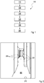
- an initial position, that is to say a starting position, of the mobile communication unit is first of all carried out in a step 110 using a navigation application implemented on the at least one mobile communication unit determined in a three-dimensional real space surrounding the mobile communication unit, in particular in a living space, and provided as the first point in a three-dimensional coordinate system.
- the three-dimensional coordinate system is virtually superimposed on the real space, especially the living space.
- an access point of the wireless local communication network for example a router of a WLAN
- the navigation application calculates a position of the router in the three-dimensional real space and provides it as a second point in the coordinate system.
- the router or its position in the room provides a kind of anchor point for the coordinate system to be superimposed on the room and for the coverage area of the WLAN to be visualized within the three-dimensional real room, i. H. of the living space.
- the mobile communication unit that is to say, from a plurality of different positions of the mobile communication unit in the space surrounding the mobile communication unit, ie within the living space, which are each provided by the navigation application as further points in the coordinate system the smartphone, a respective value of a reception quality, for example by measuring the RSSI, of signals sent from the access point, ie the router, through the wireless local communication network, ie the WLAN, to the mobile communication unit, ie the smartphone, and measured together with the respective position of the mobile communication unit is stored as a respective pair of values.
- pairs of values are now each formed from a value of the reception quality and a position assigned to this value of the reception quality within the real space, corresponding to a respective point within the coordinate system superimposed on the space.
- a measured value of the reception quality for example in the form of the RSSI, is assigned to a respective position within the living space in which the mobile communication unit is located for measurement and is stored as a measurement pair or as a value pair.
- the database for example, being part of the mobile communication unit or at least accessible to the mobile communication unit or having a communicative connection with it.
- an evaluation application implemented on the at least one mobile communication unit extrapolates the values of the reception quality to all positions of the room that can be detected by the navigation application and thus to points of the coordinate system that are respectively assigned to the positions.
- This means that the respectively measured values of the reception quality at the respective positions within the room assigned to the respectively measured values of the reception quality are extrapolated to all positions of the room that can be detected by the navigation application, so that ultimately for all positions in the room that can be detected by the navigation application , a respective value for the reception quality is available.
- each position within the space that surrounds the mobile communication unit can be determined by the navigation application implemented on the mobile communication unit.
- the room is finally displayed on the display unit of the mobile communication unit together with the values of the reception quality at the positions assigned to the respective values as a reality-enhanced representation.
- a reality-enhanced representation For example, on a display of the mobile communication unit, for example a smartphone, the actually existing space is shown as an image or photo or photograph, the display of the respective values of the reception quality at respective positions assigned to the respective values within is superimposed on the room.
- the representation of the respective values of the reception quality on the respective Positions assigned to values can be designed or implemented either in color, by specific patterns or in some other way.
- the representation of the reception quality at the positions assigned to the respective values of the reception quality is superimposed as a virtual representation on the image of the actually existing three-dimensional space and thus corresponds to a reality-enhanced representation, ie an augmented reality.
- a reality-enhanced representation ie an augmented reality.
- the possibilities for displaying the reception quality at the positions in the room assigned to the respective values of the reception quality are, for example, in the Figures 2 to 4 and 6 to 8 shown.
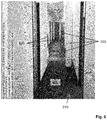
- Figure 2 shows in schematic form a possible representation of a visualization of a forecast coverage area of a wireless local communication network by means of a mobile communication unit. Shown as the space surrounding the mobile communication unit is a hallway 200 within a living room or apartment, characterized by a plurality of doors arranged laterally to rooms behind it, the hallway 200 itself extending along the doors. In Figure 2 the extrapolation of values of a reception quality or a WLAN signal strength within the corridor 200 is shown.
- the access point or router 210 is located at the bottom right in the schematic representation of an image or photos captured by the camera of the mobile communication unit (see Figure 6 ) and was initially recognized and localized by the navigation application in the image or photo.
- a spread of the reception quality or the WLAN signal strength within the room 200 is represented by, for example, color-coded, here round objects 220. It can be seen from the coloring from, for example, yellow to red, here in the schematic representation of unfilled dots, partially filled dots and filled dots, with decreasing signal strength or reception quality, as the WLAN signal strength continues to decrease towards the end of the corridor 200 .
- the evaluation application that is implemented on the mobile communication device thus determines the WLAN signal strength at the various positions within the navigation application that can be detected of the room without a user of the mobile communication unit having to move with the mobile communication unit through the room, here the hallway 200.
- the corridor 200 As soon as the user moves together with the mobile communication unit through the room, here the corridor 200, with the help of the mobile communication unit, measurement data are collected at the respective positions within the room occupied by the mobile communication unit and with the forecast or extrapolation, the was carried out by the evaluation application of the mobile communication unit.
- the continuously recorded measurement data are used for comparison with the predicted spread of the local wireless communication network.
- the prognosis or the respective reception quality calculated by the extrapolation algorithm of the evaluation application in the form of the WLAN signal strength at the respective positions in the room can be adapted and thus improved in real time.
- the reality-enhanced display shown on the display unit of the mobile communication unit is continuously updated in real time.
- FIG 3 shows a further example of a room 300 surrounding a mobile communication unit in the form of a living space, shown schematically here, in particular a living room.
- Several devices are shown within the living room 300, which can be potential interference factors for the spread or for the coverage area of the wireless local communication network within the living room 300.
- a refrigerator 330, a television 320 and a ceiling light 310 are mentioned here as examples.
- These interfering factors are recognized by the evaluation application and can also be displayed within the coverage area of the WLAN. That means that they are within the space that is created by means of the Camera captured and as an image or photo (see Figure 7 ) is identified, identified as disruptive factors and also presented as such and, if necessary, can be provided with additional information.
- the evaluation application visualizes the extent to which the reception quality or the WLAN signal suddenly decreases in the area around one, for example behind one of the interference factors, or is hampered by these as radiation sources. In this way, a user can identify the disruptive factors and either correct them or at least act against them.
- the evaluation application can make corresponding suggestions for optimizing the coverage area of the WLAN.
- the coverage area of the WLAN is displayed in real time by the evaluation application and can thus directly help the user to understand the WLAN, for example, as a home network and to make better use of it.
- the coverage area of the WLAN is shown in the form of a honeycomb pattern 301, the respective intersection points of the honeycombs representing respective intersection points of polygons which result from the calculation of respective signal strengths at certain positions or spatial points in space 300.
- AR augmented reality
- B an edge of a table.
- the closest positions or spatial points plus their respective calculated signal strength result in the shaping points of a respective polygon.
- the orientation / inclination of a respective polygon depends on the signal strengths forming the respective polygon and the surrounding polygons.
- Figure 4 shows an alternative, here schematic representation of the coverage area of the WLAN, the reception qualities at the different positions within the room 400 being represented by respective waves 401, 402, for example in different colors, here schematically in different line widths.
- the reception quality or the respective values of the reception quality can be differentiated using different colors or line widths.
- the reception quality is indicated here, through the course of the respective waves, for example through a valley-like representation or an increase, that the reception quality is directly adjacent to one Interference factor, here for example a refrigerator 330, decreases and only increases again with a greater distance from the refrigerator 330.
- Interference factor here for example a refrigerator 330
- a device located within the local wireless communication network is recognized by the evaluation application implemented on the mobile communication unit and together with device information within the reality-enhanced representation (see Figure 9 ) is shown.
- the device information is overlaid on the actual device or the device information displayed covers the device.
- a user is enabled to recognize and locate or locate the devices connected to his home network, ie his WLAN.
- the devices are initially visually recognized by the camera of the mobile communication unit and identified as part of the home network by the evaluation application.
- the relevant data of the device are then read out via UPnP and displayed together with the device itself on the display unit of the mobile communication unit within the reality-enhanced display.
- the additional information about the device can, for example, be information about the connectivity of the device, a device name and / or a device type.
- the evaluation application that is implemented on the mobile communication unit can make targeted suggestions for improvement for the location of a particular device.
- One suggestion for improvement could be to recommend repositioning the respective device, since according to the prediction calculations by the evaluation application of the respective reception qualities of the WLAN within the room, a respective reception quality will be better when the respective device is located at a different location in the room, which is suggested to the customer to place the respective device in that location.
- This can a respective user can optimize the WLAN signal for a corresponding device by repositioning in simple steps.
- Figure 6 shows the in Figure 2
- the visualized coverage area of a wireless local communication network is shown as a photo or a reality-enhanced representation, as can be represented on a display unit according to the invention.
- the black-and-white photo shown here with the coverage area shown can also be designed as a color photo with a cover area that is optionally shown in color.
- the points symbolizing the coverage area can be marked in color, for example, so that the color of the points shows how the signal strength decreases and / or increases. For example, the color "green” stands for very good, "yellow” for good and “red” for rather poor reception quality or signal strength.
- Figure 7 shows the in Figure 3
- the calculated visualization of the coverage area of a wireless local communication network within a living space is shown as a, in particular digital, photo or as a reality-enhanced representation, as can be represented according to the invention on a display unit.
- the black-and-white representation shown here can also be in the form of a color photo with a visualization of the coverage area which may be color-coded thereon.
- Figure 8 shows the in Figure 4 Alternative visualization of the coverage area of the wireless local communication network, shown in a schematic representation, likewise in the form of a photograph or a reality-enhanced representation, as can be represented according to the invention on a display unit, for example a display, of the mobile communication unit.
- the black-and-white representation shown here can also be in the form of a color photo with a visualization of the coverage area which may be color-coded thereon.
- Figure 9 shows the in Figure 5 schematically represented display of a recognized device within a coverage area of a wireless local communication network as a photograph or as a reality-enhanced representation, as can be represented according to the invention on a display unit of the mobile communication unit, for example a smartphone.
- the device information is shown here as an extension of reality covering the real device.
Landscapes
- Engineering & Computer Science (AREA)
- Computer Networks & Wireless Communication (AREA)
- Signal Processing (AREA)
- Mobile Radio Communication Systems (AREA)
Priority Applications (2)
| Application Number | Priority Date | Filing Date | Title |
|---|---|---|---|
| ES18197923T ES2859426T3 (es) | 2018-10-01 | 2018-10-01 | Método y unidad de comunicación para visualizar un área de cobertura de una red de comunicación inalámbrica |
| EP18197923.8A EP3634029B1 (fr) | 2018-10-01 | 2018-10-01 | Procédé et unité de communication destinés à la visualisation d'une zone de couverture d'un réseau de communication sans fil |
Applications Claiming Priority (1)
| Application Number | Priority Date | Filing Date | Title |
|---|---|---|---|
| EP18197923.8A EP3634029B1 (fr) | 2018-10-01 | 2018-10-01 | Procédé et unité de communication destinés à la visualisation d'une zone de couverture d'un réseau de communication sans fil |
Publications (2)
| Publication Number | Publication Date |
|---|---|
| EP3634029A1 true EP3634029A1 (fr) | 2020-04-08 |
| EP3634029B1 EP3634029B1 (fr) | 2020-12-02 |
Family
ID=63915146
Family Applications (1)
| Application Number | Title | Priority Date | Filing Date |
|---|---|---|---|
| EP18197923.8A Active EP3634029B1 (fr) | 2018-10-01 | 2018-10-01 | Procédé et unité de communication destinés à la visualisation d'une zone de couverture d'un réseau de communication sans fil |
Country Status (2)
| Country | Link |
|---|---|
| EP (1) | EP3634029B1 (fr) |
| ES (1) | ES2859426T3 (fr) |
Cited By (2)
| Publication number | Priority date | Publication date | Assignee | Title |
|---|---|---|---|---|
| CN117596602A (zh) * | 2023-12-31 | 2024-02-23 | 浙江卡巴尔电气有限公司 | 一种无线通信在工业应用中的抗干扰方法 |
| EP4346268A1 (fr) * | 2022-09-29 | 2024-04-03 | Orange | Procédé d'optimisation, terminal de communication et automate apte à optimiser une couverture d'une zone locale par un réseau de communication sans fil |
Citations (6)
| Publication number | Priority date | Publication date | Assignee | Title |
|---|---|---|---|---|
| EP1592273A2 (fr) * | 2004-04-28 | 2005-11-02 | Avaya Technology Corp. | Procédé et dispositif de génération d'un modèle des intensités de signaux pour un point d'acces à une position arbitraire |
| US20110244892A1 (en) * | 2010-04-05 | 2011-10-06 | Powerwave Technologies, Inc. | Pico base station location and analysis using mobile devices |
| US9292951B2 (en) * | 2012-08-22 | 2016-03-22 | Cable Television Laboratories, Inc. | Service coverage identification using augmented reality |
| US9451413B1 (en) | 2015-05-14 | 2016-09-20 | Qualcomm Incorporated | Apparatus and method for providing assistance data heatmaps |
| US20170127289A1 (en) * | 2015-11-04 | 2017-05-04 | At&T Intellectual Property I, L.P. | Augmented Reality Visual Wi-Fi Signal |
| US20170243400A1 (en) * | 2016-02-18 | 2017-08-24 | Edx Wireless, Inc. | Systems and methods for augmented reality representations of networks |
-
2018
- 2018-10-01 ES ES18197923T patent/ES2859426T3/es active Active
- 2018-10-01 EP EP18197923.8A patent/EP3634029B1/fr active Active
Patent Citations (6)
| Publication number | Priority date | Publication date | Assignee | Title |
|---|---|---|---|---|
| EP1592273A2 (fr) * | 2004-04-28 | 2005-11-02 | Avaya Technology Corp. | Procédé et dispositif de génération d'un modèle des intensités de signaux pour un point d'acces à une position arbitraire |
| US20110244892A1 (en) * | 2010-04-05 | 2011-10-06 | Powerwave Technologies, Inc. | Pico base station location and analysis using mobile devices |
| US9292951B2 (en) * | 2012-08-22 | 2016-03-22 | Cable Television Laboratories, Inc. | Service coverage identification using augmented reality |
| US9451413B1 (en) | 2015-05-14 | 2016-09-20 | Qualcomm Incorporated | Apparatus and method for providing assistance data heatmaps |
| US20170127289A1 (en) * | 2015-11-04 | 2017-05-04 | At&T Intellectual Property I, L.P. | Augmented Reality Visual Wi-Fi Signal |
| US20170243400A1 (en) * | 2016-02-18 | 2017-08-24 | Edx Wireless, Inc. | Systems and methods for augmented reality representations of networks |
Cited By (3)
| Publication number | Priority date | Publication date | Assignee | Title |
|---|---|---|---|---|
| EP4346268A1 (fr) * | 2022-09-29 | 2024-04-03 | Orange | Procédé d'optimisation, terminal de communication et automate apte à optimiser une couverture d'une zone locale par un réseau de communication sans fil |
| FR3140505A1 (fr) * | 2022-09-29 | 2024-04-05 | Orange | Procédé d’optimisation, terminal de communication et automate apte à optimiser une couverture d’une zone locale par un réseau de communication sans fil |
| CN117596602A (zh) * | 2023-12-31 | 2024-02-23 | 浙江卡巴尔电气有限公司 | 一种无线通信在工业应用中的抗干扰方法 |
Also Published As
| Publication number | Publication date |
|---|---|
| ES2859426T3 (es) | 2021-10-04 |
| EP3634029B1 (fr) | 2020-12-02 |
Similar Documents
| Publication | Publication Date | Title |
|---|---|---|
| DE60220812T2 (de) | Positionsdetektion und standortverfolgung in einem drahtlosen netzwerk | |
| AT511881B1 (de) | Verfahren und system zur lokalisierung eines kommunikationsgerätes | |
| DE602004005970T2 (de) | Objektpositionsbestimmung | |
| DE202012013407U1 (de) | Positionsanzeigesystem zur Geräteortung | |
| DE102013200618A1 (de) | Erzeugen einer Innenraum-Funkkarte, Orten eines Ziels im Innenraum | |
| DE102014119082A1 (de) | Lagedetektion | |
| DE102006020139A1 (de) | System und Verfahren für die Visualisierung von Verbindbarkeitsbeziehungen in einem drahtlosen System | |
| EP2454604B1 (fr) | Procédé de calibrage d'un système de localisation basé sur le temps de propagation | |
| EP3634029B1 (fr) | Procédé et unité de communication destinés à la visualisation d'une zone de couverture d'un réseau de communication sans fil | |
| DE102018131417A1 (de) | Automatische Erzeugung von Fussgängern in einer virtuellen Simulation von Strassenkreuzungen | |
| DE60133512T2 (de) | Verfahren und System zur Darstellung der Funkumgebung auf einem Funkkommunikationsgerät | |
| DE102012222185B4 (de) | Verfahren, Vorrichtung und computerlesbares Medium zur Bildregistrierung und -Anzeige | |
| DE112020006037T5 (de) | Infrastrukturfreie rf-verfolgung in dynamischen innenraumumgebungen | |
| CN119324755A (zh) | 确定区域内无线信号强度的方法、装置及电子设备 | |
| DE102023103360B3 (de) | Verfahren zur rechnergestützten Ermittlung des Verlaufs einer Anzahl von Ausbreitungspfaden von Funkwellen zwischen einem Sender und einem Empfänger eines Funknetzes | |
| DE102014211237A1 (de) | Verfahren und System zum Erfassen mindestens eines Zustands eines Raums | |
| DE112017001558T5 (de) | Kartenanzeigesystem und Kartenanzeigeprogramm | |
| DE102010042733A1 (de) | Erfassung und Darstellung texturierter drei-dimensionaler Geometrien | |
| DE102024108867A1 (de) | Präzise ortung von funkstationen | |
| EP3009908B1 (fr) | Procédé et agencement de dispositif destinés à enregistrer, évaluer et influencer la répartition de la distribution des énergies de chauffage au sein d'une enveloppe de bâtiment | |
| DE102021205428A1 (de) | Verfahren und Einrichtung zur Analyse einer dreidimensionalen Umgebung, Computerspeichermedium und drahtloses Sensorsystem | |
| EP4014845B1 (fr) | Dispositif de sortie permettant de sortir un processus temporaire de mesure | |
| WO2020099007A1 (fr) | Procédé et dispositif pour la création d'une carte de couverture | |
| EP3078934A1 (fr) | Systeme de mesure et procede de mesure | |
| DE102015121227B4 (de) | Verfahren und System zum Detektieren von Bewegungsmustern von mobilen Endgeräten |
Legal Events
| Date | Code | Title | Description |
|---|---|---|---|
| PUAI | Public reference made under article 153(3) epc to a published international application that has entered the european phase |
Free format text: ORIGINAL CODE: 0009012 |
|
| STAA | Information on the status of an ep patent application or granted ep patent |
Free format text: STATUS: REQUEST FOR EXAMINATION WAS MADE |
|
| 17P | Request for examination filed |
Effective date: 20190404 |
|
| AK | Designated contracting states |
Kind code of ref document: A1 Designated state(s): AL AT BE BG CH CY CZ DE DK EE ES FI FR GB GR HR HU IE IS IT LI LT LU LV MC MK MT NL NO PL PT RO RS SE SI SK SM TR |
|
| AX | Request for extension of the european patent |
Extension state: BA ME |
|
| GRAP | Despatch of communication of intention to grant a patent |
Free format text: ORIGINAL CODE: EPIDOSNIGR1 |
|
| STAA | Information on the status of an ep patent application or granted ep patent |
Free format text: STATUS: GRANT OF PATENT IS INTENDED |
|
| RIC1 | Information provided on ipc code assigned before grant |
Ipc: H04W 16/20 20090101ALI20200429BHEP Ipc: H04W 24/08 20090101AFI20200429BHEP Ipc: H04W 24/10 20090101ALN20200429BHEP Ipc: H04W 84/12 20090101ALN20200429BHEP |
|
| RIC1 | Information provided on ipc code assigned before grant |
Ipc: H04W 24/08 20090101AFI20200508BHEP Ipc: H04W 24/10 20090101ALN20200508BHEP Ipc: H04W 84/12 20090101ALN20200508BHEP Ipc: H04W 16/20 20090101ALI20200508BHEP |
|
| INTG | Intention to grant announced |
Effective date: 20200529 |
|
| GRAS | Grant fee paid |
Free format text: ORIGINAL CODE: EPIDOSNIGR3 |
|
| GRAA | (expected) grant |
Free format text: ORIGINAL CODE: 0009210 |
|
| STAA | Information on the status of an ep patent application or granted ep patent |
Free format text: STATUS: THE PATENT HAS BEEN GRANTED |
|
| AK | Designated contracting states |
Kind code of ref document: B1 Designated state(s): AL AT BE BG CH CY CZ DE DK EE ES FI FR GB GR HR HU IE IS IT LI LT LU LV MC MK MT NL NO PL PT RO RS SE SI SK SM TR |
|
| REG | Reference to a national code |
Ref country code: GB Ref legal event code: FG4D Free format text: NOT ENGLISH |
|
| REG | Reference to a national code |
Ref country code: AT Ref legal event code: REF Ref document number: 1342306 Country of ref document: AT Kind code of ref document: T Effective date: 20201215 Ref country code: CH Ref legal event code: EP |
|
| REG | Reference to a national code |
Ref country code: IE Ref legal event code: FG4D Free format text: LANGUAGE OF EP DOCUMENT: GERMAN |
|
| REG | Reference to a national code |
Ref country code: DE Ref legal event code: R096 Ref document number: 502018003169 Country of ref document: DE |
|
| REG | Reference to a national code |
Ref country code: NL Ref legal event code: FP |
|
| PG25 | Lapsed in a contracting state [announced via postgrant information from national office to epo] |
Ref country code: GR Free format text: LAPSE BECAUSE OF FAILURE TO SUBMIT A TRANSLATION OF THE DESCRIPTION OR TO PAY THE FEE WITHIN THE PRESCRIBED TIME-LIMIT Effective date: 20210303 Ref country code: NO Free format text: LAPSE BECAUSE OF FAILURE TO SUBMIT A TRANSLATION OF THE DESCRIPTION OR TO PAY THE FEE WITHIN THE PRESCRIBED TIME-LIMIT Effective date: 20210302 Ref country code: RS Free format text: LAPSE BECAUSE OF FAILURE TO SUBMIT A TRANSLATION OF THE DESCRIPTION OR TO PAY THE FEE WITHIN THE PRESCRIBED TIME-LIMIT Effective date: 20201202 Ref country code: FI Free format text: LAPSE BECAUSE OF FAILURE TO SUBMIT A TRANSLATION OF THE DESCRIPTION OR TO PAY THE FEE WITHIN THE PRESCRIBED TIME-LIMIT Effective date: 20201202 |
|
| PG25 | Lapsed in a contracting state [announced via postgrant information from national office to epo] |
Ref country code: BG Free format text: LAPSE BECAUSE OF FAILURE TO SUBMIT A TRANSLATION OF THE DESCRIPTION OR TO PAY THE FEE WITHIN THE PRESCRIBED TIME-LIMIT Effective date: 20210302 Ref country code: SE Free format text: LAPSE BECAUSE OF FAILURE TO SUBMIT A TRANSLATION OF THE DESCRIPTION OR TO PAY THE FEE WITHIN THE PRESCRIBED TIME-LIMIT Effective date: 20201202 Ref country code: PL Free format text: LAPSE BECAUSE OF FAILURE TO SUBMIT A TRANSLATION OF THE DESCRIPTION OR TO PAY THE FEE WITHIN THE PRESCRIBED TIME-LIMIT Effective date: 20201202 Ref country code: LV Free format text: LAPSE BECAUSE OF FAILURE TO SUBMIT A TRANSLATION OF THE DESCRIPTION OR TO PAY THE FEE WITHIN THE PRESCRIBED TIME-LIMIT Effective date: 20201202 |
|
| PG25 | Lapsed in a contracting state [announced via postgrant information from national office to epo] |
Ref country code: HR Free format text: LAPSE BECAUSE OF FAILURE TO SUBMIT A TRANSLATION OF THE DESCRIPTION OR TO PAY THE FEE WITHIN THE PRESCRIBED TIME-LIMIT Effective date: 20201202 |
|
| REG | Reference to a national code |
Ref country code: LT Ref legal event code: MG9D |
|
| PG25 | Lapsed in a contracting state [announced via postgrant information from national office to epo] |
Ref country code: LT Free format text: LAPSE BECAUSE OF FAILURE TO SUBMIT A TRANSLATION OF THE DESCRIPTION OR TO PAY THE FEE WITHIN THE PRESCRIBED TIME-LIMIT Effective date: 20201202 Ref country code: RO Free format text: LAPSE BECAUSE OF FAILURE TO SUBMIT A TRANSLATION OF THE DESCRIPTION OR TO PAY THE FEE WITHIN THE PRESCRIBED TIME-LIMIT Effective date: 20201202 Ref country code: PT Free format text: LAPSE BECAUSE OF FAILURE TO SUBMIT A TRANSLATION OF THE DESCRIPTION OR TO PAY THE FEE WITHIN THE PRESCRIBED TIME-LIMIT Effective date: 20210405 Ref country code: SK Free format text: LAPSE BECAUSE OF FAILURE TO SUBMIT A TRANSLATION OF THE DESCRIPTION OR TO PAY THE FEE WITHIN THE PRESCRIBED TIME-LIMIT Effective date: 20201202 Ref country code: SM Free format text: LAPSE BECAUSE OF FAILURE TO SUBMIT A TRANSLATION OF THE DESCRIPTION OR TO PAY THE FEE WITHIN THE PRESCRIBED TIME-LIMIT Effective date: 20201202 Ref country code: CZ Free format text: LAPSE BECAUSE OF FAILURE TO SUBMIT A TRANSLATION OF THE DESCRIPTION OR TO PAY THE FEE WITHIN THE PRESCRIBED TIME-LIMIT Effective date: 20201202 Ref country code: EE Free format text: LAPSE BECAUSE OF FAILURE TO SUBMIT A TRANSLATION OF THE DESCRIPTION OR TO PAY THE FEE WITHIN THE PRESCRIBED TIME-LIMIT Effective date: 20201202 |
|
| REG | Reference to a national code |
Ref country code: DE Ref legal event code: R097 Ref document number: 502018003169 Country of ref document: DE |
|
| PG25 | Lapsed in a contracting state [announced via postgrant information from national office to epo] |
Ref country code: IS Free format text: LAPSE BECAUSE OF FAILURE TO SUBMIT A TRANSLATION OF THE DESCRIPTION OR TO PAY THE FEE WITHIN THE PRESCRIBED TIME-LIMIT Effective date: 20210402 |
|
| REG | Reference to a national code |
Ref country code: ES Ref legal event code: FG2A Ref document number: 2859426 Country of ref document: ES Kind code of ref document: T3 Effective date: 20211004 |
|
| PLBE | No opposition filed within time limit |
Free format text: ORIGINAL CODE: 0009261 |
|
| STAA | Information on the status of an ep patent application or granted ep patent |
Free format text: STATUS: NO OPPOSITION FILED WITHIN TIME LIMIT |
|
| PG25 | Lapsed in a contracting state [announced via postgrant information from national office to epo] |
Ref country code: AL Free format text: LAPSE BECAUSE OF FAILURE TO SUBMIT A TRANSLATION OF THE DESCRIPTION OR TO PAY THE FEE WITHIN THE PRESCRIBED TIME-LIMIT Effective date: 20201202 Ref country code: IT Free format text: LAPSE BECAUSE OF FAILURE TO SUBMIT A TRANSLATION OF THE DESCRIPTION OR TO PAY THE FEE WITHIN THE PRESCRIBED TIME-LIMIT Effective date: 20201202 |
|
| 26N | No opposition filed |
Effective date: 20210903 |
|
| PG25 | Lapsed in a contracting state [announced via postgrant information from national office to epo] |
Ref country code: DK Free format text: LAPSE BECAUSE OF FAILURE TO SUBMIT A TRANSLATION OF THE DESCRIPTION OR TO PAY THE FEE WITHIN THE PRESCRIBED TIME-LIMIT Effective date: 20201202 Ref country code: SI Free format text: LAPSE BECAUSE OF FAILURE TO SUBMIT A TRANSLATION OF THE DESCRIPTION OR TO PAY THE FEE WITHIN THE PRESCRIBED TIME-LIMIT Effective date: 20201202 |
|
| REG | Reference to a national code |
Ref country code: CH Ref legal event code: PL |
|
| PG25 | Lapsed in a contracting state [announced via postgrant information from national office to epo] |
Ref country code: IS Free format text: LAPSE BECAUSE OF FAILURE TO SUBMIT A TRANSLATION OF THE DESCRIPTION OR TO PAY THE FEE WITHIN THE PRESCRIBED TIME-LIMIT Effective date: 20210402 |
|
| REG | Reference to a national code |
Ref country code: BE Ref legal event code: MM Effective date: 20211031 |
|
| PG25 | Lapsed in a contracting state [announced via postgrant information from national office to epo] |
Ref country code: MC Free format text: LAPSE BECAUSE OF FAILURE TO SUBMIT A TRANSLATION OF THE DESCRIPTION OR TO PAY THE FEE WITHIN THE PRESCRIBED TIME-LIMIT Effective date: 20201202 |
|
| PG25 | Lapsed in a contracting state [announced via postgrant information from national office to epo] |
Ref country code: LU Free format text: LAPSE BECAUSE OF NON-PAYMENT OF DUE FEES Effective date: 20211001 Ref country code: BE Free format text: LAPSE BECAUSE OF NON-PAYMENT OF DUE FEES Effective date: 20211031 |
|
| PG25 | Lapsed in a contracting state [announced via postgrant information from national office to epo] |
Ref country code: LI Free format text: LAPSE BECAUSE OF NON-PAYMENT OF DUE FEES Effective date: 20211031 Ref country code: CH Free format text: LAPSE BECAUSE OF NON-PAYMENT OF DUE FEES Effective date: 20211031 |
|
| PG25 | Lapsed in a contracting state [announced via postgrant information from national office to epo] |
Ref country code: IE Free format text: LAPSE BECAUSE OF NON-PAYMENT OF DUE FEES Effective date: 20211001 |
|
| PG25 | Lapsed in a contracting state [announced via postgrant information from national office to epo] |
Ref country code: CY Free format text: LAPSE BECAUSE OF FAILURE TO SUBMIT A TRANSLATION OF THE DESCRIPTION OR TO PAY THE FEE WITHIN THE PRESCRIBED TIME-LIMIT Effective date: 20201202 |
|
| PG25 | Lapsed in a contracting state [announced via postgrant information from national office to epo] |
Ref country code: HU Free format text: LAPSE BECAUSE OF FAILURE TO SUBMIT A TRANSLATION OF THE DESCRIPTION OR TO PAY THE FEE WITHIN THE PRESCRIBED TIME-LIMIT; INVALID AB INITIO Effective date: 20181001 |
|
| PG25 | Lapsed in a contracting state [announced via postgrant information from national office to epo] |
Ref country code: MK Free format text: LAPSE BECAUSE OF FAILURE TO SUBMIT A TRANSLATION OF THE DESCRIPTION OR TO PAY THE FEE WITHIN THE PRESCRIBED TIME-LIMIT Effective date: 20201202 |
|
| PG25 | Lapsed in a contracting state [announced via postgrant information from national office to epo] |
Ref country code: TR Free format text: LAPSE BECAUSE OF FAILURE TO SUBMIT A TRANSLATION OF THE DESCRIPTION OR TO PAY THE FEE WITHIN THE PRESCRIBED TIME-LIMIT Effective date: 20201202 |
|
| PG25 | Lapsed in a contracting state [announced via postgrant information from national office to epo] |
Ref country code: MT Free format text: LAPSE BECAUSE OF FAILURE TO SUBMIT A TRANSLATION OF THE DESCRIPTION OR TO PAY THE FEE WITHIN THE PRESCRIBED TIME-LIMIT Effective date: 20201202 |
|
| REG | Reference to a national code |
Ref country code: AT Ref legal event code: MM01 Ref document number: 1342306 Country of ref document: AT Kind code of ref document: T Effective date: 20231001 |
|
| PG25 | Lapsed in a contracting state [announced via postgrant information from national office to epo] |
Ref country code: AT Free format text: LAPSE BECAUSE OF NON-PAYMENT OF DUE FEES Effective date: 20231001 |
|
| PG25 | Lapsed in a contracting state [announced via postgrant information from national office to epo] |
Ref country code: AT Free format text: LAPSE BECAUSE OF NON-PAYMENT OF DUE FEES Effective date: 20231001 |
|
| PGFP | Annual fee paid to national office [announced via postgrant information from national office to epo] |
Ref country code: NL Payment date: 20251023 Year of fee payment: 8 |
|
| PGFP | Annual fee paid to national office [announced via postgrant information from national office to epo] |
Ref country code: DE Payment date: 20251020 Year of fee payment: 8 |
|
| PGFP | Annual fee paid to national office [announced via postgrant information from national office to epo] |
Ref country code: GB Payment date: 20251024 Year of fee payment: 8 |
|
| PGFP | Annual fee paid to national office [announced via postgrant information from national office to epo] |
Ref country code: FR Payment date: 20251022 Year of fee payment: 8 |
|
| PGFP | Annual fee paid to national office [announced via postgrant information from national office to epo] |
Ref country code: ES Payment date: 20251114 Year of fee payment: 8 |
|
| PGFP | Annual fee paid to national office [announced via postgrant information from national office to epo] |
Ref country code: AT Payment date: 20260410 Year of fee payment: 5 |