EP3634054B1 - Verfahren und vorrichtung zur übertragung von dienstdaten - Google Patents
Verfahren und vorrichtung zur übertragung von dienstdaten Download PDFInfo
- Publication number
- EP3634054B1 EP3634054B1 EP18814139.4A EP18814139A EP3634054B1 EP 3634054 B1 EP3634054 B1 EP 3634054B1 EP 18814139 A EP18814139 A EP 18814139A EP 3634054 B1 EP3634054 B1 EP 3634054B1
- Authority
- EP
- European Patent Office
- Prior art keywords
- service data
- identifier
- network device
- service
- transmission mode
- Prior art date
- Legal status (The legal status is an assumption and is not a legal conclusion. Google has not performed a legal analysis and makes no representation as to the accuracy of the status listed.)
- Active
Links
Images



Classifications
-
- H—ELECTRICITY
- H04—ELECTRIC COMMUNICATION TECHNIQUE
- H04W—WIRELESS COMMUNICATION NETWORKS
- H04W4/00—Services specially adapted for wireless communication networks; Facilities therefor
- H04W4/06—Selective distribution of broadcast services, e.g. multimedia broadcast multicast service [MBMS]; Services to user groups; One-way selective calling services
-
- G—PHYSICS
- G08—SIGNALLING
- G08G—TRAFFIC CONTROL SYSTEMS
- G08G1/00—Traffic control systems for road vehicles
- G08G1/09—Arrangements for giving variable traffic instructions
- G08G1/0962—Arrangements for giving variable traffic instructions having an indicator mounted inside the vehicle, e.g. giving voice messages
- G08G1/0967—Systems involving transmission of highway information, e.g. weather, speed limits
- G08G1/096766—Systems involving transmission of highway information, e.g. weather, speed limits where the system is characterised by the origin of the information transmission
- G08G1/096783—Systems involving transmission of highway information, e.g. weather, speed limits where the system is characterised by the origin of the information transmission where the origin of the information is a roadside individual element
-
- G—PHYSICS
- G08—SIGNALLING
- G08G—TRAFFIC CONTROL SYSTEMS
- G08G1/00—Traffic control systems for road vehicles
- G08G1/09—Arrangements for giving variable traffic instructions
- G08G1/0962—Arrangements for giving variable traffic instructions having an indicator mounted inside the vehicle, e.g. giving voice messages
- G08G1/0967—Systems involving transmission of highway information, e.g. weather, speed limits
- G08G1/096766—Systems involving transmission of highway information, e.g. weather, speed limits where the system is characterised by the origin of the information transmission
- G08G1/096791—Systems involving transmission of highway information, e.g. weather, speed limits where the system is characterised by the origin of the information transmission where the origin of the information is another vehicle
-
- H—ELECTRICITY
- H04—ELECTRIC COMMUNICATION TECHNIQUE
- H04W—WIRELESS COMMUNICATION NETWORKS
- H04W24/00—Supervisory, monitoring or testing arrangements
- H04W24/02—Arrangements for optimising operational condition
-
- H—ELECTRICITY
- H04—ELECTRIC COMMUNICATION TECHNIQUE
- H04W—WIRELESS COMMUNICATION NETWORKS
- H04W28/00—Network traffic management; Network resource management
- H04W28/02—Traffic management, e.g. flow control or congestion control
- H04W28/0252—Traffic management, e.g. flow control or congestion control per individual bearer or channel
-
- H—ELECTRICITY
- H04—ELECTRIC COMMUNICATION TECHNIQUE
- H04W—WIRELESS COMMUNICATION NETWORKS
- H04W28/00—Network traffic management; Network resource management
- H04W28/02—Traffic management, e.g. flow control or congestion control
- H04W28/0268—Traffic management, e.g. flow control or congestion control using specific QoS parameters for wireless networks, e.g. QoS class identifier [QCI] or guaranteed bit rate [GBR]
-
- H—ELECTRICITY
- H04—ELECTRIC COMMUNICATION TECHNIQUE
- H04W—WIRELESS COMMUNICATION NETWORKS
- H04W28/00—Network traffic management; Network resource management
- H04W28/02—Traffic management, e.g. flow control or congestion control
- H04W28/06—Optimizing the usage of the radio link, e.g. header compression, information sizing, discarding information
-
- H—ELECTRICITY
- H04—ELECTRIC COMMUNICATION TECHNIQUE
- H04W—WIRELESS COMMUNICATION NETWORKS
- H04W4/00—Services specially adapted for wireless communication networks; Facilities therefor
- H04W4/30—Services specially adapted for particular environments, situations or purposes
- H04W4/40—Services specially adapted for particular environments, situations or purposes for vehicles, e.g. vehicle-to-pedestrians [V2P]
-
- H—ELECTRICITY
- H04—ELECTRIC COMMUNICATION TECHNIQUE
- H04W—WIRELESS COMMUNICATION NETWORKS
- H04W76/00—Connection management
- H04W76/10—Connection setup
- H04W76/11—Allocation or use of connection identifiers
-
- H—ELECTRICITY
- H04—ELECTRIC COMMUNICATION TECHNIQUE
- H04W—WIRELESS COMMUNICATION NETWORKS
- H04W76/00—Connection management
- H04W76/40—Connection management for selective distribution or broadcast
-
- G—PHYSICS
- G08—SIGNALLING
- G08G—TRAFFIC CONTROL SYSTEMS
- G08G1/00—Traffic control systems for road vehicles
- G08G1/16—Anti-collision systems
- G08G1/161—Decentralised systems, e.g. inter-vehicle communication
-
- H—ELECTRICITY
- H04—ELECTRIC COMMUNICATION TECHNIQUE
- H04L—TRANSMISSION OF DIGITAL INFORMATION, e.g. TELEGRAPHIC COMMUNICATION
- H04L67/00—Network arrangements or protocols for supporting network services or applications
- H04L67/01—Protocols
- H04L67/12—Protocols specially adapted for proprietary or special-purpose networking environments, e.g. medical networks, sensor networks, networks in vehicles or remote metering networks
-
- H—ELECTRICITY
- H04—ELECTRIC COMMUNICATION TECHNIQUE
- H04W—WIRELESS COMMUNICATION NETWORKS
- H04W92/00—Interfaces specially adapted for wireless communication networks
- H04W92/16—Interfaces between hierarchically similar devices
- H04W92/20—Interfaces between hierarchically similar devices between access points
Definitions
- Embodiments of the present invention relate to the field of communications technologies, and in particular, to a service data transmission method and an apparatus.
- V2X vehicle-to-everything
- the data needs to be uploaded to a core network by the base station.
- the core network After routing, addressing, and forwarding the data, the core network transmits the data to the base station in a downlink manner for broadcasting. Broadcasting of the V2X service is mainly performed within a range near a terminal, that is, performed within coverage of a cell in which the terminal is located or a neighboring cell.
- WO 2017/014514 teaches a V2X communication system.
- a vehicle UE i.e. a V-UE may communicate with other V-UEs or with a road side unit RSU.
- the RSU may be an eNB RSU-E or a stationary UE.
- the RSU may determine to relay i.e. broadcast the message from the V-UE to other V-UE devices.
- a service data transmission method for a vehicle-to-everything, V2X, service is provided.
- the method is performed by a first network device, and the first network device is, for example, a base station.
- the method includes: obtaining, by the first network device, first configuration information, where the first configuration information includes a first identifier and a first transmission mode corresponding to the first identifier, and the first transmission mode corresponding to the first identifier is a mode in which transmission is performed by using an access network; receiving, by the first network device, first service data and a second identifier that are sent by a terminal; determining, by the first network device based on the first identifier and the second identifier, that a transmission mode of the first service data is the first transmission mode; and transmitting the first service data based on the first transmission mode.
- the transmitting, by the first network device, the first service data based on the first transmission mode is directly and locally performed without using a core network.
- the first network device may determine, based on the second identifier sent by the terminal and the first configuration information, the transmission mode of the first service data sent by the terminal. If the second identifier matches the first identifier, the transmission mode of the first service data is the mode in which transmission is performed by using the access network. In this case, the first network device may directly transmit the first service data locally without using a core network. Obviously, a redundant step in a data transmission process is removed, thereby shortening a data transmission path, and reducing a data transmission latency.
- the obtaining, by the first network device, first configuration information includes: obtaining, by the first network device, preconfigured information, where the preconfigured information includes the first configuration information; or receiving, by the first network device, control signaling sent by a second network device, where the control signaling carries the first configuration information.
- the preconfigured information may be preconfigured on the first network device, for example, preconfigured on the first network device by a staff member, and the first network device may directly obtain the preconfigured information locally. If the first configuration information is obtained in this manner, no excessive signaling interaction needs to be performed between the first network device and another network device, so that a transmission resource can be saved.
- the preconfigured information may be preconfigured in the core network, for example, configured on an MME.
- the MME may send the preconfigured information to the first network device in advance, and the first network device stores the preconfigured information. In this case, the first network device may also directly obtain the preconfigured information locally.
- the first configuration information may be preconfigured on the second network device.
- the first network device sends a request message to the second network device, to request to obtain the first configuration information.
- the second network device may send, to the first network device, the control signaling that carries the first configuration information.
- the first network device may obtain the first configuration information when required, and may not obtain the first configuration information when not required.
- a storage resource of the first network device may also be saved provided that the first network device can normally obtain the first configuration information.
- the first identifier is a data radio bearer identifier between the terminal and the first network device, a flow identifier of a service flow to which the service data belongs, or a specific field in the flow identifier or the data radio bearer identifier; and the second identifier is the data radio bearer identifier between the terminal and the first network device, the flow identifier of the service flow to which the first service data belongs, or the specific field in the flow identifier or the data radio bearer identifier.
- the first identifier and the second identifier are identifiers of a same type or of different types.
- this example provides a plurality of optional first identifiers and second identifiers, and different first identifiers and second identifiers may be selected as required.
- the first identifier and the second identifier may have a same type.
- both the first identifier and the second identifier are the flow identifiers of the service flow to which the service data belongs.
- the first identifier and the second identifier may have different types.
- the first identifier is the specific field in the flow identifier of the service flow to which the service data belongs
- the second identifier is the flow identifier of the service flow to which the service data belongs or the bearer identifier. All cases fall within the protection scope of the examples.
- the transmitting, by the first network device, the first service data based on the first transmission mode includes: determining, by the first network device, a downlink transmission mode of second service data based on a service type of the first service data, where the second service data is service data obtained by converting the first service data to downlink data when the first service data is transmitted by using the access network, and the downlink transmission mode is a downlink broadcast mode; and transmitting, by the first network device, the second service data based on the determined downlink transmission mode.
- the first service data is transmitted in the first transmission mode.
- the data sent by the terminal first arrives at the first network device, and then is broadcast on a first network device side.
- the first transmission mode includes an uplink transmission process and a downlink transmission process. Therefore, the first network device needs to determine the downlink transmission mode.
- the first service data is service data sent by the terminal to the first network device.
- the service data obtained by converting the first service data to the downlink data when the first service data is transmitted by using the access network is referred to as the service data, in other words, the first network device needs to determine the downlink transmission mode of the second service data.
- the first network device may determine the downlink transmission mode of the second service data based on the type of the first service data.
- a type of the service data may determine a transmission range of the service data and the like. In this way, a downlink transmission mode of the service data is determined based on the type of the service data, so that a determining result is relatively accurate.
- the first service data further carries quality of service information.
- the first network device may further determine, base on the quality of service information and uplink overheads for transmitting the first service data, downlink quality of service information that needs to be satisfied for transmitting the second service data, and select a downlink bearer for the second service data based on the determined downlink quality of service information.
- the first network device further needs to determine the downlink bearer.
- the first network device may determine, based on the quality of service information carried in the first service data and the uplink overheads for transmitting the first service data, the downlink quality of service information that needs to be satisfied for transmitting the second service data, to select the downlink bearer for the second service data based on the determined downlink quality of service information.
- the downlink bearer determined in this manner is relatively compliant with an actual requirement of the second service data, and can not only be normally used to transmit the second service data, but also be used to avoid a resource waste.
- the first configuration information further includes a first broadcast indication and a downlink broadcast mode corresponding to the first broadcast indication.
- the method further includes: receiving, by the first network device, a second broadcast indication sent by the terminal; and determining, by the first network device, a downlink broadcast mode of the second service data based on the first broadcast indication, the downlink broadcast mode, and the second broadcast indication, where the downlink broadcast mode includes broadcasting in a cell in which the first network device is located, or transmitting the second service data to a cell in which a neighboring first network device is located for broadcasting, or broadcasting in a cell in which the first network device is located and transmitting the second service data to a cell in which a neighboring first network device is located for broadcasting.
- This example provides a plurality of downlink broadcast modes. Therefore, the first network device needs to select one from the plurality of downlink broadcast modes to transmit the second service data.
- the first network device may determine the downlink broadcast mode of the second service data based on the second broadcast indication sent by the terminal and the first configuration information. An appropriate downlink broadcast mode may be selected for the second service data in this manner, so that the second service data can be broadcast in an appropriate range, and better works.
- a service data transmission method for a vehicle-to-everything, V2X, service is provided.
- the method is performed by a terminal.
- the method includes: sending, by the terminal, first service data and a second identifier to a first network device, where the second identifier is used by the first network device to determine a transmission mode of the first service data; and receiving, by the terminal, second service data transmitted by the first network device in a first transmission mode, where the first transmission mode is determined based on the second identifier and is a mode in which transmission is performed by using an access network, and the second service data is service data obtained by converting the first service data to downlink data when the first service data is transmitted by using the access network.
- the receiving, by the terminal, second service data transmitted by the first network device in a first transmission mode is directly and locally performed without using a core network.
- the terminal sends not only the first service data to the first network device, but also the second identifier to the first network device.
- the first network device may determine, based on the second identifier sent by the terminal and the first configuration information, the transmission mode of the first service data sent by the terminal. If the second identifier matches the first identifier, the transmission mode of the first service data is the mode in which transmission is performed by using the access network, and the first network device may directly transmit the first service data locally without using a core network. Obviously, a redundant step in a data transmission process is removed, thereby shortening a data transmission path, and reducing a data transmission latency.
- the second identifier is a data radio bearer identifier between the terminal and the first network device, a flow identifier of a service flow to which the first service data belongs, or a specific field in the flow identifier or the data radio bearer identifier.
- the method further includes: sending, by the terminal, a second broadcast indication to the first network device, where the second broadcast indication is used by the first network device to determine a downlink broadcast mode of the second service data, where the downlink broadcast mode includes broadcasting in a cell in which the first network device is located, or transmitting the second service data to a cell in which a neighboring first network device is located for broadcasting, or broadcasting in a cell in which the first network device is located and transmitting the second service data to a cell in which a neighboring first network device is located for broadcasting.
- This example provides a plurality of downlink broadcast modes. Therefore, the first network device needs to select one from the plurality of downlink broadcast modes to transmit the second service data.
- the first network device may determine the downlink broadcast mode of the second service data based on the second broadcast indication sent by the terminal and the first configuration information. Therefore, the terminal may send the second broadcast indication to the first network device.
- An appropriate downlink broadcast mode may be selected for the second service data in this manner, so that the second service data can be broadcast in an appropriate range, and better works.
- a network device has functions for implementing the network device in the foregoing method design. These functions may be implemented by hardware, or may be implemented by hardware executing corresponding software.
- the hardware or the software includes one or more units corresponding to the functions.
- the network device includes a processing unit and a receiving unit.
- the processing unit and the receiving unit may perform corresponding functions in the method provided in any one of the first aspect or the possible designs of the first aspect.
- a terminal has functions for implementing the terminal in the foregoing method design. These functions may be implemented by hardware, or may be implemented by hardware executing corresponding software.
- the hardware or the software includes one or more units corresponding to the functions.
- the terminal includes a sending unit and a receiving unit.
- the sending unit and the receiving unit may perform corresponding functions in the method provided in any one of the second aspect or the possible designs of the second aspect.
- a technology described in this specification may be applied to various communications systems, such as a long term evolution (Long Term Evolution, LTE) system, a fifth-generation mobile communications system (5G), and another such communications system.
- LTE Long Term Evolution
- 5G fifth-generation mobile communications system
- LTE is a mainstream wireless communications technology at present.
- the D2D technology is used as an important feature and has been standardized, and supports direct communication between terminals.
- data of the V2X service may be transmitted by using the D2D technology.
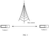
- a base station, a vehicle 1, and a vehicle 2 are included.
- the vehicle 1 and the vehicle 2 may directly communicate in a direct connection manner.
- another communication mode needs to be used.
- the vehicle may transmit the data of the V2X service to the base station, and then the base station transmits the data of the V2X service to another vehicle, to implement Internet of Vehicles communication.
- An interface used by the vehicle to communicate with a surrounding terminal in a direct connection manner may be a PC5 interface, and an interface between the vehicle and the base station may be a Uu interface.
- FIG. 2 includes a base station, an MME, a vehicle 1, a vehicle 2, and a vehicle 3.
- the vehicle 1 generates data of a V2X service that needs to be locally broadcast, the vehicle 1 sends the data to the base station, and the base station forwards the data of the V2X service to the MME in a core network.
- the MME routes, addresses, and forwards the data of the V2X service, and then sends the data of the V2X service to the base station, and the base station broadcasts the data of the V2X service.
- Broadcasting of the V2X service is mainly performed within a range near the terminal, that is, performed within coverage of a cell in which the terminal is located or a neighboring cell. It can be learned that, addressing and forwarding of the V2X data by using the core network are unnecessary steps. In addition, addressing and forwarding of the data of the V2X service by using the core network bring an unnecessary potential latency. This does not meet a low latency requirement of the V2X service.
- a first network device may determine, based on a second identifier sent by a terminal and first configuration information, a transmission mode of first service data sent by the terminal. If the second identifier matches a first identifier, the transmission mode of the first service data is a mode in which transmission is performed by using an access network. In this case, the first network device may directly transmit the first service data locally without using a core network. Obviously, a redundant step in a data transmission process is removed, thereby shortening a data transmission path, and reducing a data transmission latency.
- FIG. 3 is a schematic diagram of an application scenario according to an example.
- FIG. 3 includes a terminal 1, a terminal 2, a terminal 3, and a base station.
- the terminal 1 generates service data that needs to be locally broadcast
- the terminal 1 sends the service data to the base station, and the base station may directly broadcast the service data without using a core network.
- FIG. 4 is a schematic diagram of another application scenario according to an example.
- FIG. 4 includes a terminal 1, a terminal 2, a terminal 3, a base station 1, and a base station 2.
- the base station 1 and the base station 2 are neighboring base stations
- the terminal 1 is a terminal covered by the base station 1
- the terminal 2 and the terminal 3 are terminals covered by the base station 2.
- the terminal 1 For example, if the terminal 1 generates service data that needs to be locally broadcast, the terminal 1 sends the service data to the base station 1, the base station 1 then sends the service data to the base station 2, and the base station 2 may broadcast the service data without using a core network. In addition to the base station 2, the base station 1 may also perform broadcasting. In FIG. 4 , an example in which broadcasting is performed by only the base station 2 is used.
- An example provides a service data transmission method.
- the method may be performed by a first network device, and the first network device is, for example, a base station.
- the first network device is, for example, a base station.
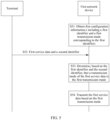
- FIG. 5 is a flowchart of the method. S51.
- the first network device obtains first configuration information.
- the first configuration information includes a first identifier and a first transmission mode corresponding to the first identifier, in other words, it may be considered that the first configuration information includes a correspondence between the first identifier and the first transmission mode.
- the first transmission mode is an end-to-end transmission mode, and is specifically a mode in which transmission is performed by using an access network.
- the mode in which transmission is performed by using the access network means that service data sent by a terminal is directly forwarded on a base station side without using a core network.
- the base station may broadcast the service data by using a Uu interface, or forward the service data to a neighboring base station by using an X2 interface.
- the first network device may obtain the first configuration information in different manners.
- the first network device may obtain preconfigured information, and the preconfigured information includes the first configuration information.
- the preconfigured information may be preconfigured on the first network device, for example, preconfigured on the first network device by a staff member, and the first network device may directly obtain the preconfigured information locally when implementing S51.
- the preconfigured information may be preconfigured in the core network, for example, configured on an MME.
- the MME may send the preconfigured information to the first network device in advance, and the first network device stores the preconfigured information. In this case, when implementing S51, the first network device may also directly obtain the preconfigured information locally.
- the first network device receives control signaling sent by a second network device, and the control signaling carries the first configuration information.
- the second network device is a device in the core network, for example, the MME.
- the first configuration information may be preconfigured on the second network device.
- the first network device may send a request message to the second network device, to request to obtain the first configuration information.
- the second network device may send the control signaling that carries the first configuration information to the first network device.
- This example does not limit a manner in which the first network device obtains the first configuration information.
- the first identifier may be a bearer identifier of an uplink bearer between the terminal and the access network.
- the first identifier may be a data radio bearer (Data Radio Bearer, DRB) identifier, where the DRB is a bearer between the terminal and an air interface of the base station, and is used to carry user plane data.
- DRB Data Radio Bearer
- the first identifier may be a specific field in the data radio bearer identifier, a flow identifier of a service flow to which the service data belongs, a specific field in the flow identifier, or a temporarily defined identifier. This is not limited in this example.
- the first identifier may include an identifier corresponding to a non-IP service of V2X, for example, include a bearer identifier of an uplink bearer between the terminal and the core network when the non-IP service of V2X is processed, or include a flow identifier of a service flow to which service data of the non-IP service of V2X belongs. Broadcasting of a V2X service is mainly performed in a range near the terminal, that is, performed within coverage of a cell in which the terminal is located or a neighboring cell, and the non-IP service of V2X does not require addressing. Therefore, addressing and forwarding of the non-IP service data of V2X by using the core network are unnecessary steps. Therefore, in this example, the mode in which transmission is performed by using the access network without using the core network may be set for the non-IP service of V2X, thereby reducing the redundant steps and reducing a latency.
- the terminal sends service data and a second identifier to the first network device, and the first network device receives the service data and the second identifier that are sent by the terminal.
- the service data is referred to as first service data.
- the second identifier may be added to the first service data and sent together with the first service data, or the second identifier and the first service data may be sent as two independent parts.
- the terminal may send the first service data and the second identifier together, or may first send the first service data and then send the second identifier, or may first send the second identifier and then send the first service data. This is not limited in this example.
- the second identifier may be the bearer identifier of the uplink bearer between the terminal and the access network, for example, the DRB identifier, or the second identifier may be a specific field in the bearer identifier, for example, the specific field in the DRB identifier, or the second identifier may be the flow identifier of the service flow to which the first service data belongs, the specific field in the flow identifier, or the temporarily defined identifier. This is not limited in this example.
- the first identifier and the second identifier may be identifiers of a same type.
- both the first identifier and the second identifier are bearer identifiers, or both the first identifier and the second identifier are flow identifiers.
- the first identifier and the second identifier may be identifiers of different types.
- the first identifier is the bearer identifier
- the second identifier is the flow identifier
- the first identifier is the bearer identifier
- the second identifier is the specific field in the bearer identifier.
- the first network device determines, based on the first identifier and the second identifier, that a transmission mode of the first service data is the first transmission mode. It may be understood that the first network device determines the transmission mode of the first service data based on the second identifier and the first configuration information.
- the first network device After receiving the second identifier, the first network device matches the second identifier with the first identifier. If the second identifier successfully matches the first identifier, the first network device may consider the first service data as service data of the non-IP service of V2X, and determine the transmission mode of the first service data to be the first transmission mode. However, if the second identifier fails to match the first identifier, the first service data may not be the service data of the non-IP service of V2X. For such first service data, the first network device may transmit the first service data according to a specification in the prior art, for example, transmit the first service data by using the mode in which transmission is performed by using the core network.
- the service data sent by the terminal is forwarded by the base station and the core network, and then transmitted to a peer terminal by the base station.
- the first network device may still transmit the first service data based on the first transmission mode. This is specifically set by a system or specified in a protocol.
- the first network device determines that the first identifier successfully matches the second identifier; otherwise, the first network device determines that the first identifier fails to match the second identifier.
- the first network device may store the correspondence between the first identifier and the second identifier in advance. In this case, if the first network device determines that a correspondence exists between the received second identifier and any first identifier in the first configuration information, the first network device determines that the first identifier successfully matches the second identifier; and if the first network device determines that no correspondence exists between the received second identifier and any first identifier in the first configuration information, the first network device determines that the first identifier fails to match the second identifier.
- the correspondence between the first identifier and the second identifier may also be included, for example, in the preconfigured information, or the second network device may send the first configuration information and the correspondence between the first identifier and the second identifier to the first network device by using the control signaling, or the first network device may obtain the correspondence between the first identifier and the second identifier in another manner. This is not limited in this example.
- S54. The first network device transmits the first service data based on the determined first transmission mode, and the terminal receives the first service data transmitted by the first network device in the first transmission mode. To be specific, if the first identifier successfully matches the second identifier, the first network device transmits the first service data based on the first transmission mode.
- the first service data is transmitted in the first transmission mode.
- the first transmission mode data sent by the terminal first arrives at the base station, and then is broadcast on the base station side. That is, the first transmission mode includes an uplink transmission process and a downlink transmission process, and the uplink transmission process is actually completed in S52. Therefore, in this case, the downlink transmission process remains to be completed.
- the first transmission mode may also include different downlink transmission modes. Therefore, the first network device needs to determine a downlink transmission mode of the first service data.
- the first service data is the service data sent by the terminal to the first network device.
- service data obtained by converting the first service data to downlink data when the first service data is transmitted by using the access network is referred to as second service data, in other words, the first network device needs to determine the downlink transmission mode of the second service data.
- second service data service data obtained by converting the first service data to downlink data when the first service data is transmitted by using the access network
- the first network device needs to determine the downlink transmission mode of the second service data.
- the first service data and the second service data are same data, and different names are given to distinguish the uplink transmission process from the downlink transmission process.
- the first network device may determine the downlink transmission mode of the second service data based on a type of the first service data.
- the first service data may be broadcast service data of the non-IP service of V2X. Therefore, the type of the first service data may be a "broadcast type", and the first network device may determine a downlink transmission mode corresponding to the service data of the "broadcast type". For example, the first network device determines that the downlink transmission mode corresponding to the service data of the "broadcast type" is the downlink broadcast mode, that is, determines that the downlink transmission mode of the first service data is the downlink broadcast mode.
- this example provides a plurality of downlink broadcast modes, and the first network device needs to select one from the plurality of downlink broadcast modes to transmit the second service data.
- the plurality of downlink broadcast modes include, but are not limited to, broadcasting in a cell in which the base station is located, or transmitting the second service data to a cell in which a neighboring base station is located for broadcasting, or broadcasting in a cell in which the base station is located and transmitting the second service data to a cell in which a neighboring base station is located for broadcasting.
- the mode of broadcasting in the cell in which the base station is located may be applied to the application scenario shown in FIG. 3
- the mode of transmitting the second service data to the cell in which the neighboring base station is located for broadcasting, or broadcasting in the cell in which the base station is located and transmitting the second service data to the cell in which the neighboring base station is located for broadcasting may be applied to the application scenario shown in FIG. 4 .
- the plurality of downlink broadcast modes include broadcasting in a cell in which the first network device is located, or transmitting the second service data to a cell in which a neighboring first network device is located for broadcasting, or broadcasting in a cell in which the first network device is located and transmitting the second service data to a cell in which a neighboring first network device is located for broadcasting.
- the first network device may determine the downlink broadcast mode of the second service data based on a second broadcast indication, a first broadcast indication, and a downlink broadcast mode. It may be understood as that the first network device may determine the downlink broadcast mode of the second service data based on the second broadcast indication and a correspondence between a broadcast indication and a broadcast mode.
- the first configuration information may further include the first broadcast indication and a downlink broadcast mode corresponding to the first broadcast indication, that is, include a correspondence between the first broadcast indication and the downlink broadcast mode.
- the terminal in addition to sending the first service data and the second identifier to the first network device, the terminal may further send the second broadcast indication to the first network device, and the first network device receives the second broadcast indication.
- the second broadcast indication may be added to the first service data and sent with the first service data together, or the second broadcast indication and the first service data may be sent as two independent parts.
- the terminal may send the first service data and the second broadcast indication together, or may first send the first service data and then send the second broadcast indication, or may first send the second broadcast indication and then send the first service data. This is not limited in this example.
- the first network device may match the first broadcast indication with the second broadcast indication, and if the second broadcast indication successfully matches any first broadcast indication included in the first configuration information, the first network device determines that a downlink broadcast mode corresponding to the successfully matched first broadcast indication in the first configuration information is the downlink broadcast mode of the second service data. If the second broadcast indication fails to match all first broadcast indications included in the first configuration information, the first network device may select any downlink broadcast mode for the second service data, or the first network device may use another transmission mode to transmit the second service data. This is not limited in this example.
- the first broadcast indication is, for example, a temporarily specified identifier
- the second broadcast indication is also, for example, a temporarily specified identifier.
- the first broadcast indication and the second broadcast indication may be set in a same manner or different manners. If the first broadcast indication and the second broadcast indication are set in the same manner, that is, if the first broadcast indication is the same as the second broadcast indication, the first network device determines that the first broadcast indication successfully matches the second broadcast indication; otherwise, the first network device determines that the first broadcast indication fails to match the second broadcast indication. If the first broadcast indication and the second broadcast indication are set in different manners, a correspondence may exist between the first broadcast indication and the second broadcast indication.
- the first network device determines that the second broadcast indication successfully matches the first broadcast indication in the first configuration information; and if no correspondence exists between the second broadcast indication and any first broadcast indication included in the first configuration information, the first network device determines that the second broadcast indication fails to match the first broadcast indication.
- the first network device may further determine a downlink bearer of the second service data.
- the first network device may determine the downlink bearer of the second service data based on quality of service (Quality of Service, QoS) information sent by the terminal and uplink overheads for transmitting the first service data.
- QoS Quality of Service
- the terminal in addition to sending the first service data and the second identifier to the first network device, the terminal may further send the QoS information to the first network device, and the first network device receives the QoS information.
- the QoS information may be added to the first service data and sent together with the first service data, or the QoS information and the first service data may be sent as two independent parts.
- the terminal may send the first service data and the QoS information together, or may first send the first service data and then send the QoS information, or may first send the QoS information and then send the first service data. This is not limited in this example.
- the first network device may learn the uplink overheads for transmitting the first service data. Therefore, the first network device may correspondingly deduce, based on the received QoS information and the uplink overheads for transmitting the first service data, downlink QoS information that needs to be satisfied for transmitting the second service data. For example, the first network device may deduce, based on the received QoS information and the uplink overheads for transmitting the first service data, a latency that needs to be satisfied by the downlink bearer for transmitting the second service data.
- the first network device determines, based on the received QoS information, an uplink packet loss rate for transmitting the first service data
- a packet loss rate that the downlink bearer for transmitting the second service data needs to satisfy may be deduced based on the uplink packet loss rate and the uplink overheads for transmitting the first service data.
- the first network device determines the downlink QoS information is not limited in this example. After determining the downlink QoS information, the first network device may select the downlink bearer for the second service data based on the downlink QoS information, and determine the downlink bearer for transmitting the second service data.
- the first network device transmits the second service data, based on the determined downlink transmission mode, that is, the selected downlink broadcast mode, by using the selected downlink bearer.
- the terminal receives the first service data transmitted by the first network device in the first transmission mode.
- the terminal receives the second service data transmitted by the first network device in the first transmission mode.
- the first service data is directly transmitted in a loopback manner by using the base station without using the core network, and the redundant step in the data transmission process is removed, thereby shortening the data transmission path and reducing the data transmission latency.
- the network device includes a receiver 601 and a processor 602.
- the processor 602 may include a central processing unit (central processor unit, CPU) or an application-specific integrated circuit (Application Specific Integrated Circuit, ASIC), one or more integrated circuits configured to control program execution, a hardware circuit developed by using a field programmable gate array (Field Programmable Gate Array, FPGA), or a baseband chip.
- CPU central processor unit
- ASIC Application Specific Integrated Circuit
- FPGA Field Programmable Gate Array
- the receiver 601 is, for example, an antenna or a communications interface, and is configured to communicate with an external device.
- the network device may further include a memory 603, which is shown in FIG. 6 together with the receiver 601 and the processor 602.
- the memory 603 is not a mandatory component, and therefore is drawn in a form of a dashed-line box in FIG. 6 , to be distinguished from the mandatory components.
- the memory 603 may include a read-only memory (Read Only Memory, ROM), a random access memory (Random Access Memory, RAM), a magnetic disk memory, or the like.
- the memory 603 may be configured to store program code required by the processor 602 for executing a task, and may be further configured to store data.
- the receiver 601 and the memory 603 may be connected to the processor 602 by using a system bus, or may be each connected to the processor 602 by using a dedicated connection cable (this is used as an example in FIG. 6 ).
- the receiver 601 is configured to receive first service data and a second identifier that are sent by a terminal.
- the processor 602 is configured to: obtain first configuration information, where the first configuration information includes a first identifier and a first transmission mode corresponding to the first identifier, and the first transmission mode corresponding to the first identifier is a mode in which transmission is performed by using an access network; determine a transmission mode of the first service data based on the first identifier, the second identifier, and the first transmission mode; and transmit the first service data based on the determined transmission mode.
- the receiver 601 may be configured to perform S52 in the example shown in FIG. 5 , and if the first network device in S51 in the example shown in FIG. 5 receives the control signaling sent by the MME, the receiver 601 is also configured to perform S51, and/or support another process of the technologies described in this specification.
- the processor 602 may be configured to perform S51, S53, and S54 in the example shown in FIG. 5 , and/or support another process of the technologies described in this specification. All related content of the steps in the foregoing method example may be cited in functional descriptions of corresponding functional modules, and details are not described herein again.
- the network device may be the first network device in the example shown in FIG. 5 .
- the terminal includes a receiver 701 and a transmitter 702.
- the receiver 701 is, for example, an antenna or a communications interface, and is configured to communicate with an external device.
- the transmitter 702 is, for example, an antenna or a communications interface, and is configured to communicate with the external device.
- the terminal may further include a processor 703, which is shown in FIG. 7 together with the receiver 701 and the transmitter 702.
- the processor 703 is not a mandatory component, and therefore is drawn in a form of a dashed box in FIG. 7 , to be distinguished from the mandatory components.
- the processor 703 may include a CPU or an ASIC, one or more integrated circuits configured to control program execution, a hardware circuit developed by using an FPGA, or a baseband chip.
- the terminal may further include a memory 704, which is shown in FIG. 7 together with the receiver 701 and the transmitter 702.
- the memory 704 is not a mandatory component, and therefore is drawn in a form of a dashed-line box in FIG. 7 , to be distinguished from the mandatory components.
- the memory 704 may include a ROM, a RAM, a magnetic disk memory, and the like.
- the memory 704 may be configured to store program code required by the processor 703 for executing a task, and may be further configured to store data.
- the receiver 701, the transmitter 702, and the memory 704 may be connected to the processor 703 by using a system bus, or may be each connected to the processor 703 by using a dedicated connection cable (this is used as an example in FIG. 7 ).
- the transmitter 702 is configured to send first service data and a second identifier to a first network device, where the second identifier is used by the first network device to determine a transmission mode of the first service data.
- the receiver 701 is configured to receive second service data transmitted by the first network device in a first transmission mode.
- the first transmission mode is determined based on the second identifier and is a mode in which transmission is performed by using an access network
- the second service data is service data obtained by converting the first service data to downlink data when the first service data is transmitted by using the access network.
- the transmitter 702 may be configured to perform S52 in the example shown in FIG. 5 , and/or support another process of the technologies described in this specification.
- the receiver 701 may be configured to perform S54 in the example shown in FIG. 5 , and/or support another process of the technologies described in this specification. All related content of the steps in the foregoing method example may be cited in functional descriptions of corresponding functional modules, and details are not described herein again.
- the terminal may be the terminal in the example shown in FIG. 5 .
- the network device provided in the example shown in FIG. 6 may alternatively be implemented in another form.
- the network device includes a receiving unit and a processing unit that are connected to each other.
- the receiving unit may be configured to perform S52 in the example shown in FIG. 5 , and if the first network device in S51 in the example shown in FIG. 5 receives the control signaling sent by the MME, the receiving unit is also configured to perform S51, and/or support another process of the technologies described in this specification.
- the processing unit may be configured to perform S51, S53, and S54 in the example shown in FIG. 5 , and/or support another process of the technologies described in this specification. All related content of the steps in the foregoing method example may be cited in functional descriptions of corresponding functional modules, and details are not described herein again.
- the terminal provided in the example shown in FIG. 7 may alternatively be implemented in another form.
- the terminal includes a sending unit and a receiving unit.
- the sending unit may be configured to perform S52 in the example shown in FIG. 5 , and/or support another process of the technologies described in this specification.
- the receiving unit may be configured to perform S54 in the example shown in FIG. 5 , and/or support another process of the technologies described in this specification. All related content of the steps in the foregoing method example may be cited in functional descriptions of corresponding functional modules, and details are not described herein again.
- the network device and the terminal provided in this example may be configured to perform the service data transmission method, for technical effects that can be achieved by the network device and the terminal, refer to the foregoing method example, and details are not described herein again.
- These computer program instructions may be provided for a general-purpose computer, a special-purpose computer, an embedded processor, or a processor of any other programmable data processing device to generate a machine, so that the instructions executed by a computer or a processor of any other programmable data processing device generate an apparatus for implementing a specific function in one or more processes in the flowcharts and/or in one or more blocks in the block diagrams.
- All or some of the foregoing examples may be implemented by using software, hardware, firmware, or any combination thereof.
- the examples may be implemented completely or partially in a form of a computer program product.
- the computer program product includes one or more computer instructions.
- the computer may be a general-purpose computer, a special-purpose computer, a computer network, or another programmable apparatus.
- the computer instructions may be stored in a computer-readable storage medium or may be transmitted from a computer-readable storage medium to another readable storage medium.
- the computer instructions may be transmitted from a website, computer, server, or data center to another web site, computer, server, or data center in a wired (for example, a coaxial cable, an optical fiber, or a digital subscriber line (DSL)) or wireless (for example, infrared, radio, and microwave, or the like) manner.
- the computer-readable storage medium may be any usable medium accessible by a computer, or a data storage device, such as a server or a data center, integrating one or more usable media.
- the usable medium may be a magnetic medium (for example, a floppy disk, a hard disk, or a magnetic tape), an optical medium (for example, a DVD), a semiconductor medium (for example, a solid-state drive (Solid State Disk, SSD)), or the like.
- a magnetic medium for example, a floppy disk, a hard disk, or a magnetic tape
- an optical medium for example, a DVD
- a semiconductor medium for example, a solid-state drive (Solid State Disk, SSD)
Landscapes
- Engineering & Computer Science (AREA)
- Computer Networks & Wireless Communication (AREA)
- Signal Processing (AREA)
- Multimedia (AREA)
- Life Sciences & Earth Sciences (AREA)
- Atmospheric Sciences (AREA)
- Physics & Mathematics (AREA)
- General Physics & Mathematics (AREA)
- Mobile Radio Communication Systems (AREA)
- Data Exchanges In Wide-Area Networks (AREA)
Claims (16)
- Verfahren zur Übertragung von Dienstdaten für einen Fahrzeug-zu-allem-Dienst, V2X-Dienst, umfassend:Erlangen (S51), durch ein erstes Netzwerkgerät, erster Konfigurationsinformationen, wobei die ersten Konfigurationsinformationen eine erste Kennung und einen ersten Übertragungsmodus, der der ersten Kennung entspricht, umfassen und der erste Übertragungsmodus, der der ersten Kennung entspricht, ein Modus ist, in dem Übertragung unter Verwendung eines Zugangsnetzwerks durchgeführt wird;Empfangen, durch das erste Netzwerkgerät, von ersten Dienstdaten und einer zweiten Kennung, die von einem Endgerät gesendet werden;Bestimmen (S53), durch das erste Netzwerkgerät, basierend auf der ersten Kennung und der zweiten Kennung, dass ein Übertragungsmodus der ersten Dienstdaten der erste Übertragungsmodus ist; undÜbertragen (S54), durch das erste Netzwerkgerät, der ersten Dienstdaten basierend auf dem ersten Übertragungsmodus; wobeidas Übertragen (S54), durch das erste Netzwerkgerät, der ersten Dienstdaten basierend auf dem ersten Übertragungsmodus direkt und lokal ohne Verwendung eines Kernnetzwerks durchgeführt wird.
- Verfahren nach Anspruch 1, wobei das Erlangen (S51), durch ein erstes Netzwerkgerät, erster Konfigurationsinformationen Folgendes umfasst:Erlangen, durch das erste Netzwerkgerät, von vorkonfigurierten Informationen, wobei die vorkonfigurierten Informationen die ersten Konfigurationsinformationen umfassen; oderEmpfangen, durch das erste Netzwerkgerät, von Steuersignalisierung, die von einem zweiten Netzwerkgerät gesendet wird, wobei die Steuersignalisierung die ersten Konfigurationsinformationen trägt.
- Verfahren nach Anspruch 1 oder 2, wobeidie erste Kennung eine Datenfunkträgerkennung zwischen dem Endgerät und dem ersten Netzwerkgerät, eine Flusskennung eines Dienstflusses, zu dem die ersten Dienstdaten gehören, oder ein spezifisches Feld in der Flusskennung oder der Datenfunkträgerkennung ist; unddie zweite Kennung die Datenfunkträgerkennung zwischen dem Endgerät und dem ersten Netzwerkgerät, die Flusskennung des Dienstflusses, zu dem die ersten Dienstdaten gehören, oder das spezifische Feld in der Flusskennung oder der Datenfunkträgerkennung ist, wobeidie erste Kennung und die zweite Kennung Kennungen eines gleichen Typs oder unterschiedlicher Typen sind.
- Verfahren nach Anspruch 1 oder 2, wobei das Übertragen (S54), durch das erste Netzwerkgerät, der ersten Dienstdaten basierend auf dem ersten Übertragungsmodus Folgendes umfasst:Bestimmen, durch das erste Netzwerkgerät, eines Downlink-Übertragungsmodus zweiter Dienstdaten basierend auf einem Diensttyp der ersten Dienstdaten, wobei die zweiten Dienstdaten Dienstdaten sind, die durch Umwandeln der ersten Dienstdaten in Downlink-Daten erlangt werden, wenn die ersten Dienstdaten unter Verwendung des Zugangsnetzwerks übertragen werden, und der Downlink-Übertragungsmodus ein Downlink-Rundruf-Modus ist; undÜbertragen, durch das erste Netzwerkgerät, der zweiten Dienstdaten basierend auf dem bestimmten Downlink-Übertragungsmodus.
- Verfahren nach Anspruch 4, wobei die ersten Dienstdaten ferner Dienstgüteinformationen tragen und das Verfahren ferner Folgendes umfasst:Bestimmen, durch das erste Netzwerkgerät, basierend auf den Dienstgüteinformationen und Uplink-Overheads zum Übertragen der ersten Dienstdaten, von Downlink-Dienstgüteinformationen, die zum Übertragen der zweiten Dienstdaten erfüllt sein müssen; undAuswählen, durch das erste Netzwerkgerät, eines Downlink-Trägers für die zweiten Dienstdaten basierend auf den Downlink-Dienstgüteinformationen.
- Verfahren zur Übertragung von Dienstdaten für einen Fahrzeug-zu-allem-Dienst, V2X-Dienst, umfassend:Senden (S52), durch ein Endgerät, von ersten Dienstdaten und einer zweiten Kennung an ein erstes Netzwerkgerät, wobei die zweite Kennung durch das erste Netzwerkgerät verwendet wird, um einen Übertragungsmodus der ersten Dienstdaten zu bestimmen; undEmpfangen, durch das Endgerät, von zweiten Dienstdaten, die durch das erste Netzwerkgerät in einem ersten Übertragungsmodus übertragen werden, wobei der erste Übertragungsmodus basierend auf der zweiten Kennung bestimmt wird und ein Modus ist, in dem Übertragung unter Verwendung eines Zugangsnetzwerks durchgeführt wird, und die zweiten Dienstdaten Dienstdaten sind, die durch Umwandeln der ersten Dienstdaten in Downlink-Daten erlangt werden, wenn die ersten Dienstdaten unter Verwendung des Zugangsnetzwerks übertragen werden; wobeidas Empfangen, durch das Endgerät, von zweiten Dienstdaten, die durch das erste Netzwerkgerät in einem ersten Übertragungsmodus übertragen werden, direkt und lokal ohne Verwendung eines Kernnetzwerks durchgeführt wird.
- Verfahren nach Anspruch 6, wobei die zweite Kennung eine Datenfunkträgerkennung zwischen dem Endgerät und dem ersten Netzwerkgerät, eine Flusskennung eines Dienstflusses, zu dem die ersten Dienstdaten gehören, oder ein spezifisches Feld in der Flusskennung oder der Datenfunkträgerkennung ist.
- Verfahren nach Anspruch 6 oder 7, wobei das Verfahren ferner Folgendes umfasst:
Senden, durch das Endgerät, einer zweiten Rundruf-Anzeige an das erste Netzwerkgerät, wobei die zweite Rundruf-Anzeige durch das erste Netzwerkgerät verwendet wird, um einen Downlink-Rundruf-Modus der zweiten Dienstdaten zu bestimmen, wobei der Downlink-Rundruf-Modus Übermitteln per Rundruf in einer Zelle, in der sich das erste Netzwerkgerät befindet, oder Übertragen der zweiten Dienstdaten an eine Zelle, in der sich ein benachbartes erstes Netzwerkgerät zum Übermitteln per Rundruf befindet, oder Übermitteln per Rundruf in einer Zelle, in der sich das erste Netzwerkgerät befindet, und Übertragen der zweiten Dienstdaten an eine Zelle, in der sich ein benachbartes erstes Netzwerkgerät zum Übermitteln per Rundruf befindet, umfasst. - Netzwerkgerät, das dazu konfiguriert ist, für einen Fahrzeug-zu-allem-Dienst, V2X-Dienst, verwendet zu werden, umfassend:einen Prozessor (602), der dazu konfiguriert ist, erste Konfigurationsinformationen zu erlangen (S51), wobei die ersten Konfigurationsinformationen eine erste Kennung und einen ersten Übertragungsmodus, der der ersten Kennung entspricht, umfassen und der erste Übertragungsmodus, der der ersten Kennung entspricht, ein Modus ist, in dem Übertragung unter Verwendung eines Zugangsnetzwerks durchgeführt wird; undeinen Empfänger (601), der dazu konfiguriert ist, erste Dienstdaten und eine zweite Kennung, die von einem Endgerät gesendet werden, zu empfangen (S52), wobeider Prozessor (602) ferner zu Folgendem konfiguriert ist:Bestimmen (S53), basierend auf der ersten Kennung und der zweiten Kennung, dass ein Übertragungsmodus der ersten Dienstdaten der erste Übertragungsmodus ist; und Übertragen (S54) der ersten Dienstdaten basierend auf dem ersten Übertragungsmodus; wobeidie Übertragung (S54), durch den Prozessor (602), der ersten Dienstdaten basierend auf dem ersten Übertragungsmodus direkt und lokal ohne Verwendung eines Kernnetzwerks durchgeführt wird.
- Netzwerkgerät nach Anspruch 9, wobei
der Prozessor (602) ferner zu Folgendem konfiguriert ist:Erlangen von vorkonfigurierten Informationen, wobei die vorkonfigurierten Informationen die ersten Konfigurationsinformationen umfassen; oderEmpfangen, unter Verwendung des Empfängers (601), von Steuersignalisierung, die von einem zweiten Netzwerkgerät gesendet wird, wobei die Steuersignalisierung die ersten Konfigurationsinformationen trägt. - Netzwerkgerät nach Anspruch 9 oder 10, wobeidie erste Kennung eine Datenfunkträgerkennung zwischen dem Endgerät und einem ersten Netzwerkgerät, eine Flusskennung eines Dienstflusses, zu dem die ersten Dienstdaten gehören, oder ein spezifisches Feld in der Flusskennung oder der Datenfunkträgerkennung ist; unddie zweite Kennung die Datenfunkträgerkennung zwischen dem Endgerät und dem ersten Netzwerkgerät, die Flusskennung des Dienstflusses, zu dem die ersten Dienstdaten gehören, oder das spezifische Feld in der Flusskennung oder der Datenfunkträgerkennung ist, wobeidie erste Kennung und die zweite Kennung Kennungen eines gleichen Typs oder unterschiedlicher Typen sind.
- Netzwerkgerät nach Anspruch 9 oder 10, wobei dass der Prozessor (602) dazu konfiguriert ist, die ersten Dienstdaten basierend auf dem ersten Übertragungsmodus zu übertragen (S54), Folgendes umfasst:Bestimmen eines Downlink-Übertragungsmodus zweiter Dienstdaten basierend auf einem Diensttyp der ersten Dienstdaten, wobei die zweiten Dienstdaten Dienstdaten sind, die durch Umwandeln der ersten Dienstdaten in Downlink-Daten erlangt werden, wenn die ersten Dienstdaten unter Verwendung des Zugangsnetzwerks übertragen werden, und der Downlink-Übertragungsmodus ein Downlink-Rundruf-Modus ist; undÜbertragen der zweiten Dienstdaten basierend auf dem bestimmten Downlink-Übertragungsmodus.
- Netzwerkgerät nach Anspruch 12, wobei die ersten Dienstdaten ferner Dienstgüteinformationen tragen und der Prozessor (602) ferner zu Folgendem konfiguriert ist:Bestimmen (S53), basierend auf den Dienstgüteinformationen und Uplink-Overheads zum Übertragen der ersten Dienstdaten, von Downlink-Dienstgüteinformationen, die zum Übertragen der zweiten Dienstdaten erfüllt sein müssen; undAuswählen eines Downlink-Trägers für die zweiten Dienstdaten basierend auf den Downlink-Dienstgüteinformationen.
- Endgerät, umfassend:einen Transmitter (702), der dazu konfiguriert ist, erste Dienstdaten und eine zweite Kennung an ein erstes Netzwerkgerät, das für einen Fahrzeug-zu-allem-Dienst, V2X-Dienst verwendbar ist, zu senden (S52), wobei die zweite Kennung durch das erste Netzwerkgerät verwendet wird, um einen Übertragungsmodus der ersten Dienstdaten zu bestimmen; undeinen Empfänger (701), der dazu konfiguriert ist, zweite Dienstdaten, die durch das erste Netzwerkgerät in einem ersten Übertragungsmodus übertragen (S54) werden, zu empfangen, wobei der erste Übertragungsmodus basierend auf der zweiten Kennung bestimmt wird und ein Modus ist, in dem Übertragung unter Verwendung eines Zugangsnetzwerks durchgeführt wird, und die zweiten Dienstdaten Dienstdaten sind, die durch Umwandeln der ersten Dienstdaten in Downlink-Daten erlangt werden, wenn die ersten Dienstdaten unter Verwendung des Zugangsnetzwerks übertragen werden; wobeider Empfang, durch den Empfänger, der ersten Dienstdaten basierend auf dem ersten Übertragungsmodus direkt und lokal ohne Verwendung eines Kernnetzes durchgeführt wird.
- Endgerät nach Anspruch 14, wobei die zweite Kennung eine Datenfunkträgerkennung zwischen dem Endgerät und dem ersten Netzwerkgerät, eine Flusskennung eines Dienstflusses, zu dem die ersten Dienstdaten gehören, oder ein spezifisches Feld in der Flusskennung oder der Datenfunkträgerkennung ist.
- Endgerät nach Anspruch 14 oder 15, wobei der Transmitter (702) ferner zu Folgendem konfiguriert ist:
Senden einer zweiten Rundruf-Anzeige an das erste Netzwerkgerät, wobei die zweite Rundruf-Anzeige durch das erste Netzwerkgerät verwendet wird, um einen Downlink-Rundruf-Modus der zweiten Dienstdaten zu bestimmen, wobei der Downlink-Rundruf-Modus Übermitteln per Rundruf in einer Zelle, in der sich das erste Netzwerkgerät befindet, oder Übertragen der zweiten Dienstdaten an eine Zelle, in der sich ein benachbartes erstes Netzwerkgerät zum Übermitteln per Rundruf befindet, oder Übermitteln per Rundruf in einer Zelle, in der sich das erste Netzwerkgerät befindet, und Übertragen der zweiten Dienstdaten an eine Zelle, in der sich ein benachbartes erstes Netzwerkgerät zum Übermitteln per Rundruf befindet, umfasst.
Applications Claiming Priority (2)
| Application Number | Priority Date | Filing Date | Title |
|---|---|---|---|
| CN201710434630.3A CN109041078B (zh) | 2017-06-09 | 2017-06-09 | 一种业务数据传输方法及装置 |
| PCT/CN2018/087159 WO2018223824A1 (zh) | 2017-06-09 | 2018-05-16 | 一种业务数据传输方法及装置 |
Publications (3)
| Publication Number | Publication Date |
|---|---|
| EP3634054A1 EP3634054A1 (de) | 2020-04-08 |
| EP3634054A4 EP3634054A4 (de) | 2020-04-22 |
| EP3634054B1 true EP3634054B1 (de) | 2025-01-29 |
Family
ID=64566963
Family Applications (1)
| Application Number | Title | Priority Date | Filing Date |
|---|---|---|---|
| EP18814139.4A Active EP3634054B1 (de) | 2017-06-09 | 2018-05-16 | Verfahren und vorrichtung zur übertragung von dienstdaten |
Country Status (6)
| Country | Link |
|---|---|
| US (1) | US20200162854A1 (de) |
| EP (1) | EP3634054B1 (de) |
| CN (1) | CN109041078B (de) |
| AU (1) | AU2018279551B2 (de) |
| MX (1) | MX2019014767A (de) |
| WO (1) | WO2018223824A1 (de) |
Families Citing this family (6)
| Publication number | Priority date | Publication date | Assignee | Title |
|---|---|---|---|---|
| CN111836402A (zh) * | 2019-04-18 | 2020-10-27 | 华为技术有限公司 | 一种数据传输方法及装置 |
| CN115390554A (zh) | 2019-11-28 | 2022-11-25 | 华为技术有限公司 | 一种设计运行区域odd判断方法、装置及相关设备 |
| CN110868747B (zh) * | 2019-11-28 | 2020-09-25 | 上海商米科技集团股份有限公司 | 一种可应用于多网络模式检测延时并自动切换的方法 |
| CN114079878B (zh) * | 2020-08-14 | 2023-05-23 | 维沃移动通信有限公司 | 数据传输方法、装置及通信设备 |
| US12464584B2 (en) * | 2023-02-09 | 2025-11-04 | T-Mobile Usa, Inc. | Low latency edge processing for drone wireless links |
| WO2026000213A1 (zh) * | 2024-06-25 | 2026-01-02 | Oppo广东移动通信有限公司 | 一种数据传输方法、装置、设备、芯片和存储介质 |
Family Cites Families (12)
| Publication number | Priority date | Publication date | Assignee | Title |
|---|---|---|---|---|
| US8812684B1 (en) * | 2006-09-28 | 2014-08-19 | Rockwell Automation Technologies, Inc. | Messaging configuration system |
| WO2010130092A1 (zh) * | 2009-05-13 | 2010-11-18 | 华为技术有限公司 | 一种实现无线ip多媒体通信的方法及系统 |
| CN101969369A (zh) * | 2009-07-27 | 2011-02-09 | 中兴通讯股份有限公司 | 一种多输入多输出传输模式的切换方法、系统及装置 |
| CN102355728A (zh) * | 2011-09-29 | 2012-02-15 | 电信科学技术研究院 | 一种传输模式信息传输的方法及装置 |
| CN103037512B (zh) * | 2011-09-30 | 2016-06-01 | 上海贝尔股份有限公司 | 一种基于模式的消息传输的方法 |
| CN103188759B (zh) * | 2011-12-31 | 2016-08-03 | 华为技术有限公司 | 承载模式选择的方法、分组网关和策略与计费控制功能实体 |
| US9844046B2 (en) * | 2013-04-01 | 2017-12-12 | Panasonic Intellectual Property Corporation Of America | Terminal, base station, method of generating DMRS, and transmission method |
| US9900872B2 (en) * | 2013-04-17 | 2018-02-20 | Futurewei Technologies, Inc. | Systems and methods for adaptive transmissions in wireless network |
| KR102274730B1 (ko) * | 2014-11-26 | 2021-07-08 | 삼성전자주식회사 | 전자 장치 및 전자 장치에서의 정보 전송 방법 |
| US10750325B2 (en) * | 2015-07-17 | 2020-08-18 | Lg Electronics Inc. | Method and apparatus for transmitting data via road side unit in wireless communication system |
| CN106559201A (zh) * | 2015-09-25 | 2017-04-05 | 中兴通讯股份有限公司 | 传输方式的指示方法及装置 |
| CN106658351B (zh) * | 2015-11-02 | 2019-07-23 | 中兴通讯股份有限公司 | 车联网v2x业务的转发方法及装置 |
-
2017
- 2017-06-09 CN CN201710434630.3A patent/CN109041078B/zh active Active
-
2018
- 2018-05-16 AU AU2018279551A patent/AU2018279551B2/en not_active Expired - Fee Related
- 2018-05-16 WO PCT/CN2018/087159 patent/WO2018223824A1/zh not_active Ceased
- 2018-05-16 EP EP18814139.4A patent/EP3634054B1/de active Active
- 2018-05-16 MX MX2019014767A patent/MX2019014767A/es unknown
-
2019
- 2019-11-25 US US16/693,696 patent/US20200162854A1/en not_active Abandoned
Also Published As
| Publication number | Publication date |
|---|---|
| CN109041078B (zh) | 2021-05-18 |
| US20200162854A1 (en) | 2020-05-21 |
| EP3634054A1 (de) | 2020-04-08 |
| AU2018279551B2 (en) | 2021-05-27 |
| MX2019014767A (es) | 2020-02-07 |
| WO2018223824A1 (zh) | 2018-12-13 |
| CN109041078A (zh) | 2018-12-18 |
| AU2018279551A1 (en) | 2019-12-19 |
| EP3634054A4 (de) | 2020-04-22 |
Similar Documents
| Publication | Publication Date | Title |
|---|---|---|
| US10728827B2 (en) | Service message sending method, terminal device, and network device | |
| CN111901847B (zh) | sidelink中继通信方法、装置、设备及介质 | |
| CN113630849B (zh) | 网络切片的选择方法、无线接入设备和终端 | |
| AU2018279551B2 (en) | Service data transmission method and apparatus | |
| EP3410663B1 (de) | Verfahren zum senden von nachrichten und vorrichtungen | |
| US10904848B2 (en) | Synchronization method of user equipment in wireless communication system and user equipment using method | |
| CN107409402B (zh) | 用于车辆通信智能无线电接入区的方法、装置、系统和计算机程序 | |
| JPWO2018030306A1 (ja) | 通信装置及びプロセッサ | |
| JP2019520765A (ja) | 無線通信システムにおけるネットワークスライスベースのnrのためのセル特定手順を実行する方法及び装置 | |
| US20190058980A1 (en) | V2x communication method and apparatus | |
| EP3016473A1 (de) | Benutzerendgerät, prozessor und basisstation | |
| US20240097845A1 (en) | Method and apparatus for determining transmission resource, and communication device and storage medium | |
| US20240031065A1 (en) | Communication method and communication apparatus | |
| CN114640963A (zh) | 旁链路通信方法及设备 | |
| US20250008371A1 (en) | Communication method and apparatus, and storage medium | |
| WO2024033295A2 (en) | U2u relay discovery and (re-)selection | |
| EP4068819A1 (de) | Kommunikationsverfahren, endgerät und netzwerkvorrichtung | |
| US12414090B2 (en) | Resource indication method, resource determining method, and related apparatus | |
| EP3562235A1 (de) | Dienstdatenübertragungsverfahren, erster kommunikationsknoten und basisstation | |
| CN115209570A (zh) | 用在用户设备中的装置 | |
| WO2017132994A1 (zh) | 信息发送、接收、上行同步、数据发送指示方法及设备 | |
| US20250227728A1 (en) | Sl ue relay enhancements | |
| CA3167947C (en) | Sidelink relay communication method and apparatus, device and medium | |
| CN118510052A (zh) | 一种侧行链路通信方法以及相关装置 | |
| CN121842654A (zh) | 一种通信方法及装置 |
Legal Events
| Date | Code | Title | Description |
|---|---|---|---|
| STAA | Information on the status of an ep patent application or granted ep patent |
Free format text: STATUS: THE INTERNATIONAL PUBLICATION HAS BEEN MADE |
|
| PUAI | Public reference made under article 153(3) epc to a published international application that has entered the european phase |
Free format text: ORIGINAL CODE: 0009012 |
|
| STAA | Information on the status of an ep patent application or granted ep patent |
Free format text: STATUS: REQUEST FOR EXAMINATION WAS MADE |
|
| REG | Reference to a national code |
Ref country code: DE Ref legal event code: R079 Free format text: PREVIOUS MAIN CLASS: H04W0072040000 Ipc: H04W0004060000 |
|
| 17P | Request for examination filed |
Effective date: 20191129 |
|
| AK | Designated contracting states |
Kind code of ref document: A1 Designated state(s): AL AT BE BG CH CY CZ DE DK EE ES FI FR GB GR HR HU IE IS IT LI LT LU LV MC MK MT NL NO PL PT RO RS SE SI SK SM TR |
|
| AX | Request for extension of the european patent |
Extension state: BA ME |
|
| A4 | Supplementary search report drawn up and despatched |
Effective date: 20200323 |
|
| RIC1 | Information provided on ipc code assigned before grant |
Ipc: H04W 4/06 20090101AFI20200317BHEP |
|
| DAV | Request for validation of the european patent (deleted) | ||
| DAX | Request for extension of the european patent (deleted) | ||
| STAA | Information on the status of an ep patent application or granted ep patent |
Free format text: STATUS: EXAMINATION IS IN PROGRESS |
|
| 17Q | First examination report despatched |
Effective date: 20210611 |
|
| GRAP | Despatch of communication of intention to grant a patent |
Free format text: ORIGINAL CODE: EPIDOSNIGR1 |
|
| STAA | Information on the status of an ep patent application or granted ep patent |
Free format text: STATUS: GRANT OF PATENT IS INTENDED |
|
| INTG | Intention to grant announced |
Effective date: 20240503 |
|
| GRAJ | Information related to disapproval of communication of intention to grant by the applicant or resumption of examination proceedings by the epo deleted |
Free format text: ORIGINAL CODE: EPIDOSDIGR1 |
|
| STAA | Information on the status of an ep patent application or granted ep patent |
Free format text: STATUS: EXAMINATION IS IN PROGRESS |
|
| GRAP | Despatch of communication of intention to grant a patent |
Free format text: ORIGINAL CODE: EPIDOSNIGR1 |
|
| STAA | Information on the status of an ep patent application or granted ep patent |
Free format text: STATUS: GRANT OF PATENT IS INTENDED |
|
| INTC | Intention to grant announced (deleted) | ||
| INTG | Intention to grant announced |
Effective date: 20240920 |
|
| GRAS | Grant fee paid |
Free format text: ORIGINAL CODE: EPIDOSNIGR3 |
|
| GRAA | (expected) grant |
Free format text: ORIGINAL CODE: 0009210 |
|
| STAA | Information on the status of an ep patent application or granted ep patent |
Free format text: STATUS: THE PATENT HAS BEEN GRANTED |
|
| AK | Designated contracting states |
Kind code of ref document: B1 Designated state(s): AL AT BE BG CH CY CZ DE DK EE ES FI FR GB GR HR HU IE IS IT LI LT LU LV MC MK MT NL NO PL PT RO RS SE SI SK SM TR |
|
| REG | Reference to a national code |
Ref country code: GB Ref legal event code: FG4D |
|
| REG | Reference to a national code |
Ref country code: CH Ref legal event code: EP |
|
| REG | Reference to a national code |
Ref country code: DE Ref legal event code: R096 Ref document number: 602018078864 Country of ref document: DE |
|
| REG | Reference to a national code |
Ref country code: IE Ref legal event code: FG4D |
|
| REG | Reference to a national code |
Ref country code: NL Ref legal event code: MP Effective date: 20250129 |
|
| PG25 | Lapsed in a contracting state [announced via postgrant information from national office to epo] |
Ref country code: NL Free format text: LAPSE BECAUSE OF FAILURE TO SUBMIT A TRANSLATION OF THE DESCRIPTION OR TO PAY THE FEE WITHIN THE PRESCRIBED TIME-LIMIT Effective date: 20250129 |
|
| PG25 | Lapsed in a contracting state [announced via postgrant information from national office to epo] |
Ref country code: RS Free format text: LAPSE BECAUSE OF FAILURE TO SUBMIT A TRANSLATION OF THE DESCRIPTION OR TO PAY THE FEE WITHIN THE PRESCRIBED TIME-LIMIT Effective date: 20250429 |
|
| PG25 | Lapsed in a contracting state [announced via postgrant information from national office to epo] |
Ref country code: FI Free format text: LAPSE BECAUSE OF FAILURE TO SUBMIT A TRANSLATION OF THE DESCRIPTION OR TO PAY THE FEE WITHIN THE PRESCRIBED TIME-LIMIT Effective date: 20250129 |
|
| PG25 | Lapsed in a contracting state [announced via postgrant information from national office to epo] |
Ref country code: PL Free format text: LAPSE BECAUSE OF FAILURE TO SUBMIT A TRANSLATION OF THE DESCRIPTION OR TO PAY THE FEE WITHIN THE PRESCRIBED TIME-LIMIT Effective date: 20250129 |
|
| PGFP | Annual fee paid to national office [announced via postgrant information from national office to epo] |
Ref country code: DE Payment date: 20250402 Year of fee payment: 8 |
|
| PG25 | Lapsed in a contracting state [announced via postgrant information from national office to epo] |
Ref country code: ES Free format text: LAPSE BECAUSE OF FAILURE TO SUBMIT A TRANSLATION OF THE DESCRIPTION OR TO PAY THE FEE WITHIN THE PRESCRIBED TIME-LIMIT Effective date: 20250129 |
|
| REG | Reference to a national code |
Ref country code: LT Ref legal event code: MG9D |
|
| PG25 | Lapsed in a contracting state [announced via postgrant information from national office to epo] |
Ref country code: NO Free format text: LAPSE BECAUSE OF FAILURE TO SUBMIT A TRANSLATION OF THE DESCRIPTION OR TO PAY THE FEE WITHIN THE PRESCRIBED TIME-LIMIT Effective date: 20250429 Ref country code: IS Free format text: LAPSE BECAUSE OF FAILURE TO SUBMIT A TRANSLATION OF THE DESCRIPTION OR TO PAY THE FEE WITHIN THE PRESCRIBED TIME-LIMIT Effective date: 20250529 |
|
| REG | Reference to a national code |
Ref country code: AT Ref legal event code: MK05 Ref document number: 1764606 Country of ref document: AT Kind code of ref document: T Effective date: 20250129 |
|
| PG25 | Lapsed in a contracting state [announced via postgrant information from national office to epo] |
Ref country code: HR Free format text: LAPSE BECAUSE OF FAILURE TO SUBMIT A TRANSLATION OF THE DESCRIPTION OR TO PAY THE FEE WITHIN THE PRESCRIBED TIME-LIMIT Effective date: 20250129 |
|
| PG25 | Lapsed in a contracting state [announced via postgrant information from national office to epo] |
Ref country code: PT Free format text: LAPSE BECAUSE OF FAILURE TO SUBMIT A TRANSLATION OF THE DESCRIPTION OR TO PAY THE FEE WITHIN THE PRESCRIBED TIME-LIMIT Effective date: 20250529 Ref country code: LV Free format text: LAPSE BECAUSE OF FAILURE TO SUBMIT A TRANSLATION OF THE DESCRIPTION OR TO PAY THE FEE WITHIN THE PRESCRIBED TIME-LIMIT Effective date: 20250129 |
|
| PG25 | Lapsed in a contracting state [announced via postgrant information from national office to epo] |
Ref country code: GR Free format text: LAPSE BECAUSE OF FAILURE TO SUBMIT A TRANSLATION OF THE DESCRIPTION OR TO PAY THE FEE WITHIN THE PRESCRIBED TIME-LIMIT Effective date: 20250430 Ref country code: BG Free format text: LAPSE BECAUSE OF FAILURE TO SUBMIT A TRANSLATION OF THE DESCRIPTION OR TO PAY THE FEE WITHIN THE PRESCRIBED TIME-LIMIT Effective date: 20250129 |
|
| PG25 | Lapsed in a contracting state [announced via postgrant information from national office to epo] |
Ref country code: AT Free format text: LAPSE BECAUSE OF FAILURE TO SUBMIT A TRANSLATION OF THE DESCRIPTION OR TO PAY THE FEE WITHIN THE PRESCRIBED TIME-LIMIT Effective date: 20250129 |
|
| PG25 | Lapsed in a contracting state [announced via postgrant information from national office to epo] |
Ref country code: SE Free format text: LAPSE BECAUSE OF FAILURE TO SUBMIT A TRANSLATION OF THE DESCRIPTION OR TO PAY THE FEE WITHIN THE PRESCRIBED TIME-LIMIT Effective date: 20250129 |
|
| PG25 | Lapsed in a contracting state [announced via postgrant information from national office to epo] |
Ref country code: SM Free format text: LAPSE BECAUSE OF FAILURE TO SUBMIT A TRANSLATION OF THE DESCRIPTION OR TO PAY THE FEE WITHIN THE PRESCRIBED TIME-LIMIT Effective date: 20250129 |
|
| PG25 | Lapsed in a contracting state [announced via postgrant information from national office to epo] |
Ref country code: DK Free format text: LAPSE BECAUSE OF FAILURE TO SUBMIT A TRANSLATION OF THE DESCRIPTION OR TO PAY THE FEE WITHIN THE PRESCRIBED TIME-LIMIT Effective date: 20250129 |
|
| PG25 | Lapsed in a contracting state [announced via postgrant information from national office to epo] |
Ref country code: IT Free format text: LAPSE BECAUSE OF FAILURE TO SUBMIT A TRANSLATION OF THE DESCRIPTION OR TO PAY THE FEE WITHIN THE PRESCRIBED TIME-LIMIT Effective date: 20250129 |
|
| PG25 | Lapsed in a contracting state [announced via postgrant information from national office to epo] |
Ref country code: CZ Free format text: LAPSE BECAUSE OF FAILURE TO SUBMIT A TRANSLATION OF THE DESCRIPTION OR TO PAY THE FEE WITHIN THE PRESCRIBED TIME-LIMIT Effective date: 20250129 Ref country code: EE Free format text: LAPSE BECAUSE OF FAILURE TO SUBMIT A TRANSLATION OF THE DESCRIPTION OR TO PAY THE FEE WITHIN THE PRESCRIBED TIME-LIMIT Effective date: 20250129 |
|
| PG25 | Lapsed in a contracting state [announced via postgrant information from national office to epo] |
Ref country code: RO Free format text: LAPSE BECAUSE OF FAILURE TO SUBMIT A TRANSLATION OF THE DESCRIPTION OR TO PAY THE FEE WITHIN THE PRESCRIBED TIME-LIMIT Effective date: 20250129 |
|
| PG25 | Lapsed in a contracting state [announced via postgrant information from national office to epo] |
Ref country code: SK Free format text: LAPSE BECAUSE OF FAILURE TO SUBMIT A TRANSLATION OF THE DESCRIPTION OR TO PAY THE FEE WITHIN THE PRESCRIBED TIME-LIMIT Effective date: 20250129 |
|
| REG | Reference to a national code |
Ref country code: DE Ref legal event code: R097 Ref document number: 602018078864 Country of ref document: DE |
|
| PLBE | No opposition filed within time limit |
Free format text: ORIGINAL CODE: 0009261 |
|
| STAA | Information on the status of an ep patent application or granted ep patent |
Free format text: STATUS: NO OPPOSITION FILED WITHIN TIME LIMIT |
|
| REG | Reference to a national code |
Ref country code: CH Ref legal event code: L10 Free format text: ST27 STATUS EVENT CODE: U-0-0-L10-L00 (AS PROVIDED BY THE NATIONAL OFFICE) Effective date: 20251210 |
|
| REG | Reference to a national code |
Ref country code: CH Ref legal event code: H13 Free format text: ST27 STATUS EVENT CODE: U-0-0-H10-H13 (AS PROVIDED BY THE NATIONAL OFFICE) Effective date: 20251223 |
|
| 26N | No opposition filed |
Effective date: 20251030 |
|
| PG25 | Lapsed in a contracting state [announced via postgrant information from national office to epo] |
Ref country code: LU Free format text: LAPSE BECAUSE OF NON-PAYMENT OF DUE FEES Effective date: 20250516 |
|
| PG25 | Lapsed in a contracting state [announced via postgrant information from national office to epo] |
Ref country code: CH Free format text: LAPSE BECAUSE OF NON-PAYMENT OF DUE FEES Effective date: 20250531 |
|
| GBPC | Gb: european patent ceased through non-payment of renewal fee |
Effective date: 20250516 |
|
| REG | Reference to a national code |
Ref country code: BE Ref legal event code: MM Effective date: 20250531 |
|
| PG25 | Lapsed in a contracting state [announced via postgrant information from national office to epo] |
Ref country code: MC Free format text: LAPSE BECAUSE OF FAILURE TO SUBMIT A TRANSLATION OF THE DESCRIPTION OR TO PAY THE FEE WITHIN THE PRESCRIBED TIME-LIMIT Effective date: 20250129 |
|
| PG25 | Lapsed in a contracting state [announced via postgrant information from national office to epo] |
Ref country code: GB Free format text: LAPSE BECAUSE OF NON-PAYMENT OF DUE FEES Effective date: 20250516 |
|
| PG25 | Lapsed in a contracting state [announced via postgrant information from national office to epo] |
Ref country code: IE Free format text: LAPSE BECAUSE OF NON-PAYMENT OF DUE FEES Effective date: 20250516 |
|
| PG25 | Lapsed in a contracting state [announced via postgrant information from national office to epo] |
Ref country code: BE Free format text: LAPSE BECAUSE OF NON-PAYMENT OF DUE FEES Effective date: 20250531 |
|
| PG25 | Lapsed in a contracting state [announced via postgrant information from national office to epo] |
Ref country code: FR Free format text: LAPSE BECAUSE OF NON-PAYMENT OF DUE FEES Effective date: 20250531 |