EP3634280B1 - Système d'implant rachidien - Google Patents
Système d'implant rachidien Download PDFInfo
- Publication number
- EP3634280B1 EP3634280B1 EP18814181.6A EP18814181A EP3634280B1 EP 3634280 B1 EP3634280 B1 EP 3634280B1 EP 18814181 A EP18814181 A EP 18814181A EP 3634280 B1 EP3634280 B1 EP 3634280B1
- Authority
- EP
- European Patent Office
- Prior art keywords
- shaft
- bone fastener
- thread
- tissue
- recited
- Prior art date
- Legal status (The legal status is an assumption and is not a legal conclusion. Google has not performed a legal analysis and makes no representation as to the accuracy of the status listed.)
- Active
Links
Images


Classifications
-
- A—HUMAN NECESSITIES
- A61—MEDICAL OR VETERINARY SCIENCE; HYGIENE
- A61B—DIAGNOSIS; SURGERY; IDENTIFICATION
- A61B17/00—Surgical instruments, devices or methods
- A61B17/56—Surgical instruments or methods for treatment of bones or joints; Devices specially adapted therefor
- A61B17/58—Surgical instruments or methods for treatment of bones or joints; Devices specially adapted therefor for osteosynthesis, e.g. bone plates, screws or setting implements
- A61B17/88—Osteosynthesis instruments; Methods or means for implanting or extracting internal or external fixation devices
- A61B17/8802—Equipment for handling bone cement or other fluid fillers
- A61B17/8805—Equipment for handling bone cement or other fluid fillers for introducing fluid filler into bone or extracting it
- A61B17/8811—Equipment for handling bone cement or other fluid fillers for introducing fluid filler into bone or extracting it characterised by the introducer tip, i.e. the part inserted into or onto the bone
-
- A—HUMAN NECESSITIES
- A61—MEDICAL OR VETERINARY SCIENCE; HYGIENE
- A61B—DIAGNOSIS; SURGERY; IDENTIFICATION
- A61B17/00—Surgical instruments, devices or methods
- A61B17/56—Surgical instruments or methods for treatment of bones or joints; Devices specially adapted therefor
- A61B17/58—Surgical instruments or methods for treatment of bones or joints; Devices specially adapted therefor for osteosynthesis, e.g. bone plates, screws or setting implements
- A61B17/68—Internal fixation devices, including fasteners and spinal fixators, even if a part thereof projects from the skin
- A61B17/70—Spinal positioners or stabilisers, e.g. stabilisers comprising fluid filler in an implant
- A61B17/7001—Screws or hooks combined with longitudinal elements which do not contact vertebrae
- A61B17/7032—Screws or hooks with U-shaped head or back through which longitudinal rods pass
-
- A—HUMAN NECESSITIES
- A61—MEDICAL OR VETERINARY SCIENCE; HYGIENE
- A61B—DIAGNOSIS; SURGERY; IDENTIFICATION
- A61B17/00—Surgical instruments, devices or methods
- A61B17/56—Surgical instruments or methods for treatment of bones or joints; Devices specially adapted therefor
- A61B17/58—Surgical instruments or methods for treatment of bones or joints; Devices specially adapted therefor for osteosynthesis, e.g. bone plates, screws or setting implements
- A61B17/68—Internal fixation devices, including fasteners and spinal fixators, even if a part thereof projects from the skin
- A61B17/70—Spinal positioners or stabilisers, e.g. stabilisers comprising fluid filler in an implant
- A61B17/7097—Stabilisers comprising fluid filler in an implant, e.g. balloon; devices for inserting or filling such implants
- A61B17/7098—Stabilisers comprising fluid filler in an implant, e.g. balloon; devices for inserting or filling such implants wherein the implant is permeable or has openings, e.g. fenestrated screw
-
- A—HUMAN NECESSITIES
- A61—MEDICAL OR VETERINARY SCIENCE; HYGIENE
- A61B—DIAGNOSIS; SURGERY; IDENTIFICATION
- A61B17/00—Surgical instruments, devices or methods
- A61B17/56—Surgical instruments or methods for treatment of bones or joints; Devices specially adapted therefor
- A61B17/58—Surgical instruments or methods for treatment of bones or joints; Devices specially adapted therefor for osteosynthesis, e.g. bone plates, screws or setting implements
- A61B17/68—Internal fixation devices, including fasteners and spinal fixators, even if a part thereof projects from the skin
- A61B17/84—Fasteners therefor or fasteners being internal fixation devices
- A61B17/86—Pins or screws or threaded wires; nuts therefor
- A61B17/864—Pins or screws or threaded wires; nuts therefor hollow, e.g. with socket or cannulated
-
- A—HUMAN NECESSITIES
- A61—MEDICAL OR VETERINARY SCIENCE; HYGIENE
- A61B—DIAGNOSIS; SURGERY; IDENTIFICATION
- A61B17/00—Surgical instruments, devices or methods
- A61B17/34—Trocars; Puncturing needles
- A61B17/3472—Trocars; Puncturing needles for bones, e.g. intraosseus injections
-
- A—HUMAN NECESSITIES
- A61—MEDICAL OR VETERINARY SCIENCE; HYGIENE
- A61B—DIAGNOSIS; SURGERY; IDENTIFICATION
- A61B17/00—Surgical instruments, devices or methods
- A61B17/56—Surgical instruments or methods for treatment of bones or joints; Devices specially adapted therefor
- A61B17/58—Surgical instruments or methods for treatment of bones or joints; Devices specially adapted therefor for osteosynthesis, e.g. bone plates, screws or setting implements
- A61B17/68—Internal fixation devices, including fasteners and spinal fixators, even if a part thereof projects from the skin
- A61B17/70—Spinal positioners or stabilisers, e.g. stabilisers comprising fluid filler in an implant
- A61B17/7001—Screws or hooks combined with longitudinal elements which do not contact vertebrae
- A61B17/7035—Screws or hooks, wherein a rod-clamping part and a bone-anchoring part can pivot relative to each other
- A61B17/7037—Screws or hooks, wherein a rod-clamping part and a bone-anchoring part can pivot relative to each other wherein pivoting is blocked when the rod is clamped
-
- A—HUMAN NECESSITIES
- A61—MEDICAL OR VETERINARY SCIENCE; HYGIENE
- A61B—DIAGNOSIS; SURGERY; IDENTIFICATION
- A61B17/00—Surgical instruments, devices or methods
- A61B17/56—Surgical instruments or methods for treatment of bones or joints; Devices specially adapted therefor
- A61B17/58—Surgical instruments or methods for treatment of bones or joints; Devices specially adapted therefor for osteosynthesis, e.g. bone plates, screws or setting implements
- A61B17/68—Internal fixation devices, including fasteners and spinal fixators, even if a part thereof projects from the skin
- A61B17/84—Fasteners therefor or fasteners being internal fixation devices
- A61B17/86—Pins or screws or threaded wires; nuts therefor
- A61B17/8625—Shanks, i.e. parts contacting bone tissue
- A61B17/863—Shanks, i.e. parts contacting bone tissue with thread interrupted or changing its form along shank, other than constant taper
-
- A—HUMAN NECESSITIES
- A61—MEDICAL OR VETERINARY SCIENCE; HYGIENE
- A61B—DIAGNOSIS; SURGERY; IDENTIFICATION
- A61B17/00—Surgical instruments, devices or methods
- A61B2017/0042—Surgical instruments, devices or methods with special provisions for gripping
- A61B2017/00455—Orientation indicators, e.g. recess on the handle
-
- A—HUMAN NECESSITIES
- A61—MEDICAL OR VETERINARY SCIENCE; HYGIENE
- A61B—DIAGNOSIS; SURGERY; IDENTIFICATION
- A61B17/00—Surgical instruments, devices or methods
- A61B17/56—Surgical instruments or methods for treatment of bones or joints; Devices specially adapted therefor
- A61B17/58—Surgical instruments or methods for treatment of bones or joints; Devices specially adapted therefor for osteosynthesis, e.g. bone plates, screws or setting implements
- A61B17/68—Internal fixation devices, including fasteners and spinal fixators, even if a part thereof projects from the skin
- A61B17/84—Fasteners therefor or fasteners being internal fixation devices
- A61B17/86—Pins or screws or threaded wires; nuts therefor
- A61B2017/8655—Pins or screws or threaded wires; nuts therefor with special features for locking in the bone
-
- A—HUMAN NECESSITIES
- A61—MEDICAL OR VETERINARY SCIENCE; HYGIENE
- A61B—DIAGNOSIS; SURGERY; IDENTIFICATION
- A61B90/00—Instruments, implements or accessories specially adapted for surgery or diagnosis and not covered by any of the groups A61B1/00 - A61B50/00, e.g. for luxation treatment or for protecting wound edges
- A61B90/08—Accessories or related features not otherwise provided for
- A61B2090/0807—Indication means
- A61B2090/0811—Indication means for the position of a particular part of an instrument with respect to the rest of the instrument, e.g. position of the anvil of a stapling instrument
Definitions
- the present disclosure generally relates to medical devices for the treatment of spinal disorders, and more particularly to a surgical implant system including a bone fastener.
- Spinal pathologies and disorders such as scoliosis and other curvature abnormalities, kyphosis, degenerative disc disease, disc herniation, osteoporosis, spondylolisthesis, stenosis, tumor, and fracture may result from factors including trauma, disease and degenerative conditions caused by injury and aging.
- Spinal disorders typically result in symptoms including deformity, pain, nerve damage, and partial or complete loss of mobility.
- Non-surgical treatments such as medication, rehabilitation and exercise can be effective, however, may fail to relieve the symptoms associated with these disorders.
- Surgical treatment of these spinal disorders includes correction, fusion, fixation, discectomy, laminectomy and implantable prosthetics.
- spinal constructs such as vertebral rods are often used to provide stability to a treated region. Rods redirect stresses away from a damaged or defective region while healing takes place to restore proper alignment and generally support the vertebral members.
- one or more rods and bone fasteners can be delivered to a surgical site. The rods may be attached via the fasteners to the exterior of two or more vertebral members. This disclosure describes an improvement over these prior technologies.
- the present invention relates to a bone fastener as claimed hereafter. Preferred embodiments are set forth in the dependent claims.
- a bone fastener is provided.
- the bone fastener includes a shaft.
- the shaft includes a wall that defines a longitudinal cavity and a plurality of openings in communication therewith. The openings are disposed in axial alignment along the shaft and the wall is closed exclusive of the openings.
- systems, spinal constructs, spinal implants, surgical instruments are disclosed.
- exemplary embodiments of a surgical system disclosed are discussed in terms of medical devices for the treatment of musculoskeletal disorders and more particularly, in terms of a spinal implant system including a bone fastener.
- the surgical system of the present disclosure comprises a spinal implant being a bone screw including one or a plurality of openings configured to expel a biologic or agent in a selected orientation with tissue.
- the spinal implant includes a fenestrated bone screw configured for controlled cement placement.
- the surgical system of the present disclosure comprises a bone screw including one or a plurality of openings configured to disperse a biologic or agent relative to the axis of the bone screw to reduce a risk of complications to a patient, for example, extravasation adjacent areas of bone degeneration.
- the bone screw includes fenestrations disposed along only one side of the bone screw to control the direction that the biologic or agent is placed with tissue.
- the bone screw includes fenestrations disposed along only one side of the bone screw to provide a uni- directional cement deployment and enable more controlled placement.
- the bone screw includes fenestrations disposed along the same side of the bone screw to allow a surgeon to have directional control of the deployment of the cement to avoid areas of diminished bone quality. In some embodiments, the bone screw includes fenestrations that provide directional control of the cement deployment.
- the surgical system of the present disclosure comprises a spinal implant, such as, for example, a fenestrated bone screw that is engageable with tissue surfaces of one or more vertebral levels.
- the bone screw includes a proximal member, such as, for example, an implant receiver and a distal member, such as, for example, a threaded shaft.
- the bone screw can include various configurations, such as, for example, a posted screw, a pedicle screw, a bolt, a bone screw for a lateral plate, an interbody screw, a uni-axial screw (UAS), a fixed angle screw (FAS), a multi-axial screw (MAS), a side loading screw, a sagittal adjusting screw (SAS), a transverse sagittal adjusting screw (TSAS), an awl tip (ATS), a dual rod multi-axial screw (DRMAS), midline lumbar fusion screw and/or a sacral bone screw.
- UAS uni-axial screw
- FAS fixed angle screw
- MAS multi-axial screw
- SAS sagittal adjusting screw
- TSAS transverse sagittal adjusting screw
- ATS awl tip
- DRMAS dual rod multi-axial screw
- midline lumbar fusion screw and/or a sacral bone screw.
- the surgical system of the present disclosure comprises a bone screw including a fenestrated shaft that maintains cortical purchase.
- the bone screw includes fenestrations that are disposed proximally from a distal tip of the shaft.
- the bone screw includes a cannulated portion configured to extend a distance along the shaft such that the distal tip is solid.
- the positioning of the cannulated portion along a distance of the shaft is configured to prevent leakage of cement outside a vertebral body.
- the distal tip includes various configurations to facilitate engagement with tissue.
- the surgical system of the present disclosure includes a bone screw that enhances fixation with vertebrae and is used with a biologic or agent, for example, bone cement (PMMA).
- PMMA bone cement
- the surgical system of the present disclosure comprises a bone screw including indicia and/or a directional indicator of orientation of the one or plurality of openings.
- the indicia and/or directional indicator displays the orientation of deployment of a biologic or an agent from the one or plurality of openings with tissue.
- the indicia and/or directional indicator displays the orientation of a uni-directional biologic or agent deployment, which enables more controlled placement of the biologic or agent.
- the indicia and/or directional indicator includes a marking, notch, slot, bead, detent, bump, print, label, score, color coding and/or cavity disposed on a head of a bone screw shaft.
- the indicia and/or directional indicator may be disposed with a surgical instrument engageable with the bone screw and aligned with the one or plurality of openings and/or indicia disposed on the head of a bone screw shaft. In some embodiments, the indicia and/or directional indicator facilitates locating the one or plurality of openings and/or their orientation with tissue.
- the surgical system of the present disclosure comprises a bone screw including one or more groups or arrays of the one or plurality of openings disposed with the bone screw shaft.
- the groups or arrays can be spaced apart, parallel, transverse, disposed at a relative angular orientation, axially aligned, in series, offset, staggered and/or perpendicular.
- each group or array can include a row or column of one or a plurality of openings.
- the bone screw includes a first array of openings and a second array of openings disposed along the bone screw shaft such that the bone screw provides deployment of the biologic or agent to selected tissue, for example, with a selected tissue quadrant disposed about the bone screw shaft.
- the bone screw includes a first array of openings disposed along the bone screw shaft at a relative angular orientation of 60 degrees relative to a second array of openings.
- the present disclosure may be employed to treat spinal disorders such as, for example, degenerative disc disease, disc herniation, osteoporosis, spondylolisthesis, stenosis, scoliosis and other curvature abnormalities, kyphosis, tumor and fractures.
- spinal disorders such as, for example, degenerative disc disease, disc herniation, osteoporosis, spondylolisthesis, stenosis, scoliosis and other curvature abnormalities, kyphosis, tumor and fractures.
- the disclosed spinal implant system may be alternatively employed in a surgical treatment with a patient in a prone or supine position, and/or employ various surgical approaches to the spine, including anterior, posterior, posterior mid-line, lateral, postero-lateral, and/or antero-lateral approaches, and in other body regions such as maxillofacial and extremities.
- the present disclosure may also be alternatively employed with procedures for treating the lumbar, cervical, thoracic, sacral and pelvic regions of a spinal column.
- the spinal implant system of the present disclosure may also be used on animals, bone models and other non-living substrates, such as, for example, in training, testing and demonstration.
- treating or “treatment” of a disease or condition refers to performing a procedure that may include administering one or more drugs to a patient (human, normal or otherwise or other mammal), employing implantable devices, and/or employing instruments that treat the disease, such as, for example, microdiscectomy instruments used to remove portions bulging or herniated discs and/or bone spurs, in an effort to alleviate signs or symptoms of the disease or condition. Alleviation can occur prior to signs or symptoms of the disease or condition appearing, as well as after their appearance.
- treating or treatment includes preventing or prevention of disease or undesirable condition (e.g., preventing the disease from occurring in a patient, who may be predisposed to the disease but has not yet been diagnosed as having it).
- treating or treatment does not require complete alleviation of signs or symptoms, does not require a cure, and specifically includes procedures that have only a marginal effect on the patient.
- Treatment can include inhibiting the disease, e.g., arresting its development, or relieving the disease, e.g., causing regression of the disease.
- treatment can include reducing acute or chronic inflammation; alleviating pain and mitigating and inducing re- growth of new ligament, bone and other tissues; as an adjunct in surgery; and/or any repair procedure.
- tissue includes soft tissue, ligaments, tendons, cartilage and/or bone unless specifically referred to otherwise.
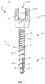
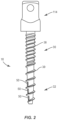
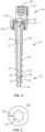
- FIGS. 1-4 there are illustrated components of a spinal implant system 10.
- the components of spinal implant system 10 can be fabricated from biologically acceptable materials suitable for medical applications, including metals, synthetic polymers, ceramics and bone material and/or their composites.
- the components of spinal implant system 10 individually or collectively, can be fabricated from materials such as stainless steel alloys, aluminum, commercially pure titanium, titanium alloys, Grade 5 titanium, super-elastic titanium alloys, cobalt-chrome alloys, superelastic metallic alloys (e.g., Nitinol, super elasto-plastic metals, such as GUM METAL ® ), ceramics and composites thereof such as calcium phosphate (e.g., SKELITETM), thermoplastics such as polyaryletherketone (PAEK) including polyetheretherketone (PEEK), polyetherketoneketone (PEKK) and polyetherketone (PEK), carbon-PEEK composites, PEEK-BaSO4 polymeric rubbers, polyethylene terephthalate (PET), fabric, silicone, polyurethane, silicone-pol
- Various components of spinal implant system 10 may have material composites, including the above materials, to achieve various desired characteristics such as strength, rigidity, elasticity, compliance, biomechanical performance, durability and radiolucency or imaging preference.
- the components of spinal implant system 10, individually or collectively, may also be fabricated from a heterogeneous material such as a combination of two or more of the above-described materials.
- the components of spinal implant system 10 may be monolithically formed, integrally connected or include fastening elements and/or instruments, as described herein.
- Bone fastener 12 is configured to facilitate selective expulsion of an agent from bone fastener 12 in a uni-directional orientation with tissue. Selective positioning of bone fastener 12 to expel an agent facilitates directional control of the agent into targeted tissue and/or healthier, less degenerated tissue to resist and/or prevent leakage of the agent and to enhance fixation, facilitate bone growth, provide therapy and/or diagnosis, as described herein.
- Bone faster 12 includes an elongated shaft 16 and a proximal head 100.
- Shaft 16 extends along an axis X1 between a proximal portion 30 and a distal tip 32.
- Portion 30 includes a proximal surface 34 having a thread 36.
- Thread 36 is oriented with shaft 16 and disposed for engagement with tissue.
- Portion 30 includes a distal surface 38 having a thread 39.
- Thread 39 is oriented with shaft 16 and disposed for engagement with tissue. Threads 36, 39 are disposed in a serial orientation along shaft 16.
- Thread 36 includes a fine, closely-spaced and/or shallow configuration to facilitate and/or enhance engagement with tissue. Thread 36 includes a smaller pitch or more thread turns per axial distance of shaft 16 relative to thread 39 such that thread 36 provides a stronger fixation with vertebral tissue and/or resists loosening from tissue. Accordingly, thread 39 includes a greater pitch or an increased lead between thread turns relative to thread 36. In some embodiments, thread 36 is continuous along shaft 16. In some embodiments, thread 39 is continuous along shaft 16.
- threads 36, 39 may be intermittent, staggered, discontinuous and/or may include a single thread turn or a plurality of discrete threads.
- other penetrating elements may be located on shaft 16, such as, for example, a nail configuration, barbs, expanding elements, raised elements, ribs, and/or spikes to facilitate engagement of shaft 16 with tissue.
- threads 36, 39 may be self-tapping or intermittent.
- Portion 30 includes a wall having an inner surface 40.
- Surface 40 defines a longitudinal cavity, such as, for example, passageway 42 such that bone fastener 12 includes a cannulated configuration.
- Passageway 42 extends along axis X1.
- Passageway 42 is configured to direct and/or guide an agent disposed therein into a vertebral body to enhance fixation, facilitate bone growth, provide therapy and/or diagnosis, as described herein.
- passageway 42 is configured to direct and/or guide bone cement into a vertebral body to facilitate fixation of bone fastener 12 with tissue, as described herein.
- Surface 40 extends between an end 44 and an end 46.
- passageway 42 extends longitudinally through bone fastener 12 such that bone fastener 12 is cannulated along the entire length of shaft 16 and tip 32, as shown in FIG. 4 .
- End 44 is connected with an axial opening 48 of head 100 disposed in communication with passageway 42.
- opening 48 is in communication with a cavity 122 of receiver 114.
- passageway 42 may be disposed in various orientations, such as, for example, perpendicular, transverse and/or at angular orientations, such as acute or obtuse relative to axis X1.
- Portion 30 includes a plurality of lateral openings, such as, for example, fenestrations 50.
- Fenestrations 50 each define a lateral passageway that extends from passageway 42 through a wall thickness of portion 30 between surfaces 34, 40.
- Fenestrations 50 are in communication with passageway 42 such that the wall of portion 30 is closed exclusive of fenestrations 50.
- Fenestrations 50 facilitate a flow of an agent from passageway 42 into a vertebral body, as described herein.
- fenestrations 50 are solely disposed in an axial alignment along passageway 42, as shown in FIG. 4 .
- Portion 30 includes three equally spaced fenestrations 50.
- fenestrations 50 are elongated and disposed in a serial orientation along passageway 42.
- fenestrations 50 may be alternately configured, such as, for example, oval, triangular, square, polygonal, irregular, uniform, non-uniform and/or tapered.
- Fenestrations 50 allow the flow of an agent disposed within passageway 42 external to shaft 16.
- fenestrations 50 are configured to selectively disperse the agent in a uni-directional orientation to target deployment of the agent to selected tissue.
- fenestrations 50 are configured to selectively disperse the agent to a selected tissue quadrant disposed about shaft 16. Selective orientation of shaft 16 and corresponding positioning of fenestrations 50 relative to targeted tissue provides directional control of dispersion of the agent. In some embodiments, such targeted deployment disperses the agent into healthier tissue to resist and/or prevent leakage of the agent from areas with diminished bone quality.
- Fenestrations 50 are disposed along a single side of shaft 16 to provide directional control of the disbursement of the agent to an area of healthy tissue and avoid areas of diminished bone quality.
- Shaft 16 can be rotated to position fenestrations 50 in alignment with targeted tissue and/or to an area of heathier tissue to avoid areas of diminished bone quality.
- deployment of an agent from bone fastener 12, as described herein, consists of selective expulsion of the agent only from fenestrations 50.
- fenestrations 50 are disposed perpendicular relative to passageway 42. In some embodiments, fenestrations 50 may be disposed at alternate orientations, relative to passageway 42, such as, for example, transverse and/or other angular orientations such as acute or obtuse, coaxial and/or may be offset or staggered. In some embodiments, fenestrations 50 include a tapered configuration. In one embodiment, as shown in FIG. 3A , shaft 16 includes an array of fenestrations 50 and an array of fenestrations 50a. Fenestrations 50, 50a are spaced apart, offset and disposed in a relatively parallel orientation along axis X1.
- Fenestrations 50, 50a provide deployment of the agent to selected tissue, for example, to a selected tissue quadrant disposed about shaft 16.
- fenestrations 50, 50a are spaced apart along shaft 16 at a relative angular orientation of 60 degrees relative to axis X1.
- the agent may include bone growth promoting material, such as, for example, bone graft to enhance fixation of bone fastener 12 and/or other components of a spinal construct with tissue, as described herein.
- bone growth promoting material such as, for example, bone graft to enhance fixation of bone fastener 12 and/or other components of a spinal construct with tissue, as described herein.
- Osteogenic material may be included in the agent such as, for example, autologous bone harvested from the patient receiving the implant device, bone allograft, bone xenograft, any number of non-bone implants (for example ceramic, metallic, polymer), bone morphogenic protein, and/or bio-resorbable compositions.
- the agent can contain other bioactive agents or other active agents, which may include one or a plurality of therapeutic agents and/or pharmacological agents for release, including sustained release, into a vertebra to treat, for example, pain, inflammation and degeneration.
- the agents may include pharmacological agents, such as, for example, antibiotics, pain medications, analgesics, anesthetics, anti-inflammatory drugs including steroids, antiviral and anti-retroviral compounds, therapeutic proteins or peptides, therapeutic nucleic acids (as naked plasmid or a component of an integrating or non-integrating gene therapy vector system), and combinations thereof.
- the agent may include bone cement that enhances fixation of bone fastener 12 with tissue.
- the bone cement may include a poly(methyl methacrylate) (PMMA); methyl methacrylate (MMA); calcium phosphate; a resorbable polymer, such as, for example, PLA, PGA or combinations thereof; a resorbable polymer with allograft, such as, for example, particles or fibers of mineralized bone and/or combinations thereof.
- PMMA poly(methyl methacrylate)
- MMA methyl methacrylate
- calcium phosphate such as, for example, PLA, PGA or combinations thereof
- a resorbable polymer with allograft such as, for example, particles or fibers of mineralized bone and/or combinations thereof.
- Tip 32 includes a surface 60 that defines a passageway 62. Passageway 62 is disposed in communication with passageway 42 such that tip 32 is cannulated to allow an agent, as described herein, to flow from tip 32.
- an agent is selectively expelled to targeted tissue via uni-directional deployment from fenestrations 50, as described herein, and through passageway 62 in a targeted deployment from tip 32.
- deployment of an agent from bone fastener 12, as described herein consists of selective expulsion of the agent only from fenestrations 50 and tip 32.
- tip 32 is tapered, for example, with a bevel for easier insertion and less tearing of the tissue.
- tip 32 includes a tapered configuration to define an awl tip to facilitate self-tapping for engagement with vertebrae.
- tip 32 has a blunt configuration.
- tip 32 includes a sharpened point.
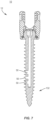
- Tip 32 may include a surface 64 having a thread 66. Thread 66 is oriented with tip 32 and disposed for engagement with tissue. Thread 66 is continuous with thread 39 along tip 32 and includes a similar configuration. In some embodiments, thread 66 may be alternatively configured, similar to threads 36, 39, described herein. In some embodiments, surface 64 is oriented at an angle in a range of 0 through 15 degrees relative to axis X1. In some embodiments, bone fastener 12 includes a tip 132 having a solid, non-cannulated configuration, as shown in the illustrative example of FIG. 7 , such that deployment of an agent from bone fastener 12, as described herein, consists of selective expulsion of the agent only from fenestrations 50, as described herein, to targeted tissue.
- the shaft 16 includes a resistance element, such as a thread 70.
- Thread 70 extends along a portion of surface 34 between adjacent crests of thread 39, as shown in FIGS. 1 and 3 . Thread 70 is separate and spaced apart from thread 39. In some embodiments, thread 70 extends in a parallel orientation relative to thread 39. In some embodiments, thread 70 may extend transverse, convergent, divergent, intersecting, staggered and/or offset relative to the thread 39.
- the resistance element such as, for example, thread 70 is configured to increase an insertion torque upon engagement of thread 70 with tissue, such as, for example, bone and/or a spinal implant, such as, for example, a cervical plate.
- the increase in torque generates and/or provides tactile indicia to a practitioner that bone fastener 12 is approaching a portion of shaft 16, such as, for example, thread 36 during engagement with bone and/or a spinal implant.
- thread 70 engages tissue and/or a spinal implant to increase an insertion torque of bone fastener 12 for generating and/or providing tactile indicia to a practitioner between a first and/or initial position and a second position.
- the tactile indicia may comprise position indicia of bone fastener 12 and/or engagement of thread 70 with tissue and/or a spinal implant may generate position indicia alone.
- Head 100 may include a socket 102 configured for engagement with a drive surface of a surgical driver instrument, as described herein.
- Socket 102 defines a hexalobular cross section for disposal and engagement of a correspondingly shaped portion of the drive surface.
- socket 102 defines a cruciform, phillips, square, polygonal or star cross sectional configuration for disposal and engagement of a correspondingly shaped portion of the drive surface.
- the surface of head 100 defining socket 102 comprises a portion of a torque interface between a surgical instrument to drive, rotate, torque, insert, implant or otherwise connect bone fastener 12 with tissue, as described herein. In one embodiment, as shown in FIG.
- head 100 includes indicia, such as, for example, a marker 90 that displays the orientation of deployment of the agent from fenestrations 50 with tissue.
- Marker 90 displays the orientation of a uni-directional agent deployment, which enables more controlled placement of the agent and/or locating fenestrations 50 and their orientation with tissue.
- marker 90 is disposed with socket 102.
- the indicia may include visual indicia, tactile indicia, audible indicia, one or more components having markers for identification under x-ray, fluoroscopy, CT or other imaging techniques, at least one light emitting diode, a wireless component, a wired component, a near field communication component and/or one or more components that generate acoustic signals, magnetic signals, electromagnetic signals and/or radiologic signals.
- the indicia includes a notch, slot, bead, detent, bump, print, label, score, color coding and/or cavity disposed on shaft 16. In some embodiments, the indicia may be attachable with or adhered to shaft 16.
- the indicia may be disposed with a surgical instrument engageable with socket 102 and aligned with fenestrations 50 and/or marker 90.
- marker 90 may be employed to display the orientation of deployment of the agent from shaft 16 including fenestrations 50, 50a with tissue.
- Bone fastener 12 may include an implant receiver 114 connectable with shaft 16. Receiver 114 extends along and defines an axis X2. Receiver 114 includes a pair of spaced apart arms 118, 120 that define an implant cavity 122 therebetween configured for disposal of a component of a spinal construct, such as, for example, a spinal rod (not shown). Arms 118, 120 extend parallel to axis X2. In some embodiments, arm 118 and/or arm 120 may be disposed at alternate orientations, relative to axis X2, such as, for example, transverse, perpendicular and/or other angular orientations such as acute or obtuse, coaxial and/or may be offset or staggered.
- Arms 118, 120 each include an arcuate outer surface extending between a pair of side surfaces. At least one of the outer surfaces and the side surfaces of arms 118, 120 have at least one recess or cavity therein configured to receive an insertion tool, compression instrument and/or instruments for inserting and tensioning bone fastener 12.
- arms 118, 120 are connected at proximal and distal ends thereof such that receiver 114 defines a closed spinal rod slot.
- the marker 90 may be located on the receiver 114 when the receiver 114 is in a fixed rotational orientation with respect to the shaft 16.
- Cavity 122 is substantially U-shaped. In some embodiments, all or only a portion of cavity 122 may have alternate cross section configurations, such as, for example, closed, V-shaped, W-shaped, oval, oblong triangular, square, polygonal, irregular, uniform, non-uniform, offset, staggered, and/or tapered.
- Receiver 114 includes an inner surface 124. A portion of surface 124 includes a thread form 126. Thread form 126 is configured for engagement with a coupling member, such as, for example, a setscrew (not shown), to retain a spinal rod within cavity 122.
- surface 124 may be disposed with the coupling member in alternate fixation configurations, such as, for example, friction fit, pressure fit, locking protrusion/recess, locking keyway and/or adhesive. In some embodiments, all or only a portion of surface 124 may have alternate surface configurations to enhance engagement with a spinal rod and/or the setscrew, such as, for example, rough, arcuate, undulating, mesh, porous, semi-porous, dimpled and/or textured. In some embodiments, receiver 14 may include alternate configurations, such as, for example, closed, open and/or side access.
- receiver 114 is connectable with shaft 16 to form a multi-axial screw (MAS).
- connection of receiver 114 with shaft 16 can be actuated by a manual engagement and/or non-instrumented assembly, which may include a practitioner, surgeon and/or medical staff grasping receiver 114 and shaft 16 and forcibly snap or pop fitting the components together.
- receiver 114 is connectable with shaft 16 to include various configurations, such as, for example, a uni-axial screw (UAS), a fixed angle screw (FAS), a side loading screw, a sagittal adjusting screw (SAS), a transverse sagittal adjusting screw (TSAS), an awl tip screw (ATS) or a sacral bone screw.
- UAS uni-axial screw
- FAS fixed angle screw
- TSAS transverse sagittal adjusting screw
- ATS awl tip screw
- spinal implant system 10 In assembly, operation and use, spinal implant system 10, similar to the systems and methods described herein, includes bone fastener 12 and is employed with a surgical procedure for treatment of a spinal disorder affecting a section of a spine of a patient, as discussed herein.
- the components of spinal implant system 10 are employed with a surgical procedure for treatment of a condition or injury of an affected section of the spine, such as, for example, vertebrae V, as shown in FIG. 6 .
- spinal implant system 10 can be used in any existing surgical method or technique including open surgery, mini-open surgery, minimally invasive surgery and percutaneous surgical implantation, whereby vertebrae V is accessed through a mini- incision, or sleeve that provides a protected passageway to the area. Once access to the surgical site is obtained, the particular surgical procedure can be performed for treating the spine disorder.
- a cutting instrument (not shown) creates a surgical pathway for implantation of components of spinal implant system 10.
- a preparation instrument (not shown) can be employed to prepare tissue surfaces of vertebrae V, as well as for aspiration and irrigation of a surgical region.
- Pilot holes are made in a vertebral level V1 of vertebrae V in a selected orientation for disposal of one or more bone fasteners 12.
- Bone fasteners 12 are engaged with a surgical driver instrument, as described herein, for orientation and disposal with the pilot holes.
- Each bone fastener 12 is aligned with the pilot hole and the driver is torqued or otherwise rotated such that shaft 16 translates axially within the pilot hole for engagement with the tissue of vertebral level V1.
- Shaft 16 is rotated causing threads 66, 39, 36, as described herein, to engage tissue of vertebra V1.
- Shaft 16 is rotated to a selected orientation relative to tissue of vertebra V1 such that fenestrations 50 are positioned relative to targeted tissue T to provide directional control and expulsion of the agent to tissue T and/or adjacent areas of vertebrae V, as described herein.
- marker 90 displays and/or locates the orientation of fenestrations 50 and/or agent deployment with tissue, as described herein.
- An injection device such as, for example, a syringe or a pump including a port for connection with opening 48 is connected with a source of an agent, as described herein. The agent is provided to bone fastener 12 via the injection device for transfer to passageway 42.
- the agent flows through passageway 42 and is selectively directed and/or guided for expulsion through fenestrations 50 to tissue T and/or through passageway 62 in a targeted deployment from tip 32.
- Fenestrations 50 are solely disposed along a side of shaft 16 in a serial and/or axial configuration to provide uni- directional deployment of the agent to tissue T, which can include healthy tissue and avoid areas of diminished bone quality.
- selective deployment of the agent to tissue T targets healthier, less degenerated tissue to resist and/or prevent leakage of the agent outside vertebra V1.
- deployment of the agent from bone fastener 12, as described herein consists of selective expulsion of the agent only from fenestrations 50.
- deployment of the agent from bone fastener 12, as described herein consists of selective expulsion of the agent only from fenestrations 50 and tip 32.
- spinal implant system 10 Upon completion of a procedure, as described herein, the surgical instruments, assemblies and non-implanted components of spinal implant system 10 are removed and the incision(s) are closed.
- One or more of the components of spinal implant system 10 can be made of radiolucent materials such as polymers. Radiomarkers may be included for identification under x-ray, fluoroscopy, CT or other imaging techniques.
- the use of surgical navigation, microsurgical and image guided technologies may be employed to access, view and repair spinal deterioration or damage, with the aid of spinal implant system 10.
- spinal implant system 10 may include one or a plurality of rods, plates, connectors and/or bone fasteners for use with a single vertebral level or a plurality of vertebral levels.
- spinal implant system 10 comprises a kit including a plurality of bone fasteners 12 of varying configuration, as described herein.
- bone fastener 12 is selected from the kit for employing with a treatment at the surgical site.
- bone fastener 12 is connected with a surgical instrument to facilitate insertion and manipulation of bone fastener 12 utilizing an image guide, such as, for example, a navigation component (not shown) of a medical imaging and navigation system (not shown), as described herein.
Landscapes
- Health & Medical Sciences (AREA)
- Orthopedic Medicine & Surgery (AREA)
- Life Sciences & Earth Sciences (AREA)
- Surgery (AREA)
- Neurology (AREA)
- Heart & Thoracic Surgery (AREA)
- Engineering & Computer Science (AREA)
- Biomedical Technology (AREA)
- Nuclear Medicine, Radiotherapy & Molecular Imaging (AREA)
- Medical Informatics (AREA)
- Molecular Biology (AREA)
- Animal Behavior & Ethology (AREA)
- General Health & Medical Sciences (AREA)
- Public Health (AREA)
- Veterinary Medicine (AREA)
- Surgical Instruments (AREA)
- Prostheses (AREA)
- Pathology (AREA)
Claims (12)
- Fixation osseuse (12) comprenant :un arbre (16) comportant une paroi (40) qui définit une cavité longitudinale (42) et une pluralité d'ouvertures (50) en communication avec celle-ci, les ouvertures (50) étant disposées en alignement axial le long de l'arbre (16) et la paroi (40) étant fermée à l'exclusion des ouvertures (50) ; etune extrémité distale (32) ;dans laquelle l'arbre (16) s'étend le long d'un axe (X1) entre une partie proximale (30) et l'extrémité distale (32),caractérisé en ce quela partie proximale (30) comporte une surface proximale (34) ayant un premier filetage (36) et une surface distale (38) ayant un second filetage (39) ;l'arbre (16) comporte en outre un élément de résistance (70) sous forme d'un filetage, qui s'étend le long d'une partie de la surface (34) entre les crêtes adjacentes du second filetage (39), dans lequel l'élément de résistance (70) est séparé et espacé du second filetage (39) ; etle premier filetage (36) comporte un pas plus petit ou plus de tours de filetage par distance axiale de l'arbre (16) par rapport au second filetage (39) de telle sorte que le premier filetage (36) assure une fixation plus solide avec le tissu vertébral et/ou résiste au desserrage du tissu.
- Fixation osseuse (12) selon la revendication 1, dans laquelle les ouvertures (50) sont disposées le long de la paroi (40) permettant d'expulser un agent destiné à un déploiement sélectionné avec le tissu.
- Fixation osseuse (12) selon la revendication 1, dans laquelle les ouvertures (50) sont disposées le long d'un seul côté de la paroi (40) permettant d'expulser sélectivement un agent dans une orientation unidirectionnelle avec le tissu.
- Fixation osseuse (12) selon la revendication 1, dans laquelle les ouvertures (50) comportent une pluralité de fenestrations latérales disposées dans une orientation en série le long de la paroi (40).
- Fixation osseuse (12) selon la revendication 1, dans laquelle les ouvertures (50) comportent trois fenestrations latérales également espacées, disposées dans une orientation en série adjacente à une surface distale de l'arbre (16).
- Fixation osseuse (12) selon la revendication 1, dans laquelle l'arbre (16) comporte une extrémité distale fermée (32).
- Fixation osseuse (12) selon la revendication 1, dans laquelle la cavité longitudinale (42) s'étend à travers l'extrémité distale (32) de l'arbre (16).
- Fixation osseuse (12) selon la revendication 1, dans laquelle l'arbre (16) comporte en outre des indications (90) de l'orientation des ouvertures (50) permettant le déploiement d'un agent avec un tissu.
- Fixation osseuse (12) selon la revendication 1, dans laquelle l'arbre (16) comporte une extrémité distale (32) ayant une conception conique.
- Fixation osseuse (12) selon la revendication 1, dans laquelle l'arbre (16) comporte une extrémité distale (32) ayant une conception émoussée.
- Fixation osseuse (12) selon la revendication 1, dans laquelle l'arbre (16) comporte une partie proximale canulée (30).
- Fixation osseuse (12) selon la revendication 1, dans laquelle la paroi (40) comporte une extrémité proximale (44) qui définit une ouverture axiale (48) disposée en communication avec la cavité longitudinale (42).
Applications Claiming Priority (2)
| Application Number | Priority Date | Filing Date | Title |
|---|---|---|---|
| US15/616,665 US10856922B2 (en) | 2017-06-07 | 2017-06-07 | Spinal implant system and method |
| PCT/US2018/033774 WO2018226391A1 (fr) | 2017-06-07 | 2018-05-22 | Système et procédé d'implant rachidien |
Publications (3)
| Publication Number | Publication Date |
|---|---|
| EP3634280A1 EP3634280A1 (fr) | 2020-04-15 |
| EP3634280A4 EP3634280A4 (fr) | 2021-03-17 |
| EP3634280B1 true EP3634280B1 (fr) | 2024-07-17 |
Family
ID=64562434
Family Applications (1)
| Application Number | Title | Priority Date | Filing Date |
|---|---|---|---|
| EP18814181.6A Active EP3634280B1 (fr) | 2017-06-07 | 2018-05-22 | Système d'implant rachidien |
Country Status (5)
| Country | Link |
|---|---|
| US (2) | US10856922B2 (fr) |
| EP (1) | EP3634280B1 (fr) |
| JP (1) | JP2020523061A (fr) |
| CN (1) | CN110662504B (fr) |
| WO (1) | WO2018226391A1 (fr) |
Families Citing this family (19)
| Publication number | Priority date | Publication date | Assignee | Title |
|---|---|---|---|---|
| US11147688B2 (en) | 2013-10-15 | 2021-10-19 | Si-Bone Inc. | Implant placement |
| US11116519B2 (en) | 2017-09-26 | 2021-09-14 | Si-Bone Inc. | Systems and methods for decorticating the sacroiliac joint |
| EP3773281B1 (fr) | 2018-03-28 | 2025-01-08 | SI-Bone, Inc. | Implants filetés pour utilisation à travers des segments osseux |
| WO2020168269A1 (fr) | 2019-02-14 | 2020-08-20 | Si-Bone Inc. | Implants de fixation et/ou de fusion vertébrale |
| US11369419B2 (en) | 2019-02-14 | 2022-06-28 | Si-Bone Inc. | Implants for spinal fixation and or fusion |
| US10918421B2 (en) | 2019-05-07 | 2021-02-16 | Warsaw Orthopedic, Inc. | Spinal implant system and methods of use |
| AU2020386985A1 (en) | 2019-11-21 | 2022-06-02 | Si-Bone Inc. | Rod coupling assemblies for bone stabilization constructs |
| ES3042147T3 (en) | 2019-11-27 | 2025-11-18 | Si Bone Inc | Bone stabilizing implants across si joints |
| JP2023504571A (ja) | 2019-12-09 | 2023-02-03 | エスアイ-ボーン・インコーポレイテッド | 仙腸関節安定化インプラント及び埋込方法 |
| US20230038914A1 (en) * | 2020-04-08 | 2023-02-09 | Spinewelding Ag | Fenestrated bone anchor |
| KR102545243B1 (ko) * | 2020-09-29 | 2023-06-20 | 주식회사 에이스메디코프 | 다공성 척추경 나사못 및 상기 나사못을 구비한 척추고정술용 수술도구 |
| KR102537768B1 (ko) * | 2020-09-29 | 2023-05-31 | 주식회사 에이스메디코프 | 본시멘트 주입형 척추경 나사못 및 상기 나사못을 구비한 척추고정술용 수술도구 |
| DE102020006464A1 (de) | 2020-10-21 | 2022-04-21 | Mimeo Medical Gmbh | Schraubenelement optimiert für den 3D-Druck |
| JP2023553120A (ja) | 2020-12-09 | 2023-12-20 | エスアイ-ボーン・インコーポレイテッド | 仙腸関節安定化インプラントおよびインプラント方法 |
| US12582536B2 (en) * | 2021-08-05 | 2026-03-24 | Surgentec, Llc | Methods, systems, and apparatuses for spinal fusion |
| US12575945B2 (en) | 2021-08-05 | 2026-03-17 | Surgentec, Llc | Methods, systems, and apparatuses for spinal fusion |
| WO2023102533A1 (fr) | 2021-12-03 | 2023-06-08 | Si-Bone Inc. | Cages intersomatique et procédés de stabilisation d'articulation sacro-iliaque |
| KR102835190B1 (ko) * | 2022-11-10 | 2025-07-18 | 한국생산기술연구원 | 복합 나사형 뼈 고정용 플레이트 |
| AU2024325368A1 (en) | 2023-08-15 | 2026-03-12 | Si-Bone Inc. | Pelvic stabilization implants, methods of use and manufacture |
Citations (1)
| Publication number | Priority date | Publication date | Assignee | Title |
|---|---|---|---|---|
| US20160324557A1 (en) * | 2015-05-06 | 2016-11-10 | Warsaw Orthopedic, Inc. | Surgical implant system and method of use |
Family Cites Families (38)
| Publication number | Priority date | Publication date | Assignee | Title |
|---|---|---|---|---|
| JP3575208B2 (ja) * | 1997-01-31 | 2004-10-13 | 三菱マテリアル株式会社 | 骨接合用螺子 |
| US6214012B1 (en) | 1998-11-13 | 2001-04-10 | Harrington Arthritis Research Center | Method and apparatus for delivering material to a desired location |
| US6210376B1 (en) * | 1999-04-08 | 2001-04-03 | New York University | Cannulated delivery pin |
| US7547302B2 (en) * | 1999-07-19 | 2009-06-16 | I-Flow Corporation | Anti-microbial catheter |
| US6517542B1 (en) * | 1999-08-04 | 2003-02-11 | The Cleveland Clinic Foundation | Bone anchoring system |
| US6280442B1 (en) * | 1999-09-01 | 2001-08-28 | Sdgi Holdings, Inc. | Multi-axial bone screw assembly |
| US6565572B2 (en) * | 2000-04-10 | 2003-05-20 | Sdgi Holdings, Inc. | Fenestrated surgical screw and method |
| US20080234756A1 (en) * | 2002-11-19 | 2008-09-25 | John Sutcliffe | Pedicle Screw |
| US7354442B2 (en) * | 2003-05-05 | 2008-04-08 | Warsaw Orthopedic, Inc. | Bone anchor and methods of using the same |
| US7608062B2 (en) * | 2003-07-15 | 2009-10-27 | Spinal Generations, Llc | Method and device for delivering medicine to bone |
| US8062270B2 (en) * | 2003-07-15 | 2011-11-22 | Spinal Generations, Llc | Method and device for delivering medicine to bone |
| US7527611B2 (en) * | 2003-07-15 | 2009-05-05 | Spinal Generations, Llc | Method and device for delivering medicine to bone |
| US8070785B2 (en) * | 2003-09-16 | 2011-12-06 | Spineco, Inc. | Bone anchor prosthesis and system |
| US7255713B2 (en) * | 2003-12-18 | 2007-08-14 | Malek Michel H | Systems and methods for agent delivery |
| US8821506B2 (en) * | 2006-05-11 | 2014-09-02 | Michael David Mitchell | Bone screw |
| US8460308B2 (en) * | 2008-10-14 | 2013-06-11 | Trinity Orthopedics, Llc. | Insertion and reduction tool for pedicle screw assembly |
| US11229457B2 (en) * | 2009-06-15 | 2022-01-25 | Roger P. Jackson | Pivotal bone anchor assembly with insert tool deployment |
| ES2535248T3 (es) * | 2009-07-01 | 2015-05-07 | Biedermann Technologies Gmbh & Co. Kg | Instrumentos para su uso con anclajes óseos con un elemento de cierre |
| US8574273B2 (en) * | 2009-09-09 | 2013-11-05 | Innovision, Inc. | Bone screws and methods of use thereof |
| US9078701B2 (en) | 2009-11-09 | 2015-07-14 | Centinel Spine, Inc. | System and method for stabilizing a posterior fusion over motion segments |
| US8608802B2 (en) * | 2009-11-20 | 2013-12-17 | Zimmer Knee Creations, Inc. | Implantable devices for subchondral treatment of joint pain |
| US8945193B2 (en) | 2010-07-20 | 2015-02-03 | X-Spine Systems, Inc. | Minimally invasive spinal facet compression screw and system for bone joint fusion and fixation |
| EP2595556A1 (fr) | 2010-07-20 | 2013-05-29 | X-spine Systems, Inc. | Vis de compression pour facettes vertébrales avec zones filetées à pas variable et tête arc-boutée |
| US8821501B2 (en) * | 2010-09-24 | 2014-09-02 | Depuy (Ireland) | Patella resectioning guide and assembly |
| JP2013545527A (ja) * | 2010-11-02 | 2013-12-26 | ロジャー・ピー・ジャクソン | ポップオン式シャンクと枢動可能な保持部とを有する多軸の骨アンカー |
| JP2014511219A (ja) * | 2011-02-03 | 2014-05-15 | アルファテック スパイン, インコーポレイテッド | 骨ねじ用材料送達装置 |
| US20120203286A1 (en) * | 2011-02-04 | 2012-08-09 | Warsaw Orthopedic, Inc. | Bone Fastener and Methods of Use |
| US9155580B2 (en) * | 2011-08-25 | 2015-10-13 | Medos International Sarl | Multi-threaded cannulated bone anchors |
| US8641736B2 (en) * | 2012-01-20 | 2014-02-04 | Warsaw Orthopedic, Inc. | Vertebral fastener system |
| EP2861157B1 (fr) * | 2012-06-14 | 2018-08-15 | Sanoculis Ltd. | Dispositif médical et ensemble de création d'un canal dans un tissu mou |
| US9603644B2 (en) * | 2012-08-07 | 2017-03-28 | Spinal Generations, Llc | Methods and devices for delivery of medicine to bone |
| US20140058461A1 (en) * | 2012-08-27 | 2014-02-27 | Michael Black | Fenestrated Bone Screw |
| US20140214081A1 (en) * | 2013-01-31 | 2014-07-31 | Warsaw Orthopedic, Inc. | Spinal implant system and method |
| EP2967694B1 (fr) | 2013-03-15 | 2022-04-20 | INNOVISION, Inc. | Vis à os |
| EP2832309B1 (fr) * | 2013-07-31 | 2018-03-07 | Biedermann Technologies GmbH & Co. KG | Implant pour des os ou des vertèbres avec souplesse auto-restrictive |
| US9364341B2 (en) * | 2014-01-09 | 2016-06-14 | Warsaw Orthopedic, Inc. | Spinal implant system and method |
| US9730771B2 (en) * | 2014-01-13 | 2017-08-15 | Brock B. WESTOVER | Endosseous dental implant assembly |
| ES2611014T3 (es) * | 2014-01-13 | 2017-05-04 | Biedermann Technologies Gmbh & Co. Kg | Conjunto de acoplamiento para acoplar una varilla a un elemento de anclaje óseo, y dispositivo de anclaje óseo poliaxial |
-
2017
- 2017-06-07 US US15/616,665 patent/US10856922B2/en active Active
-
2018
- 2018-05-22 CN CN201880033764.7A patent/CN110662504B/zh active Active
- 2018-05-22 JP JP2019565814A patent/JP2020523061A/ja active Pending
- 2018-05-22 EP EP18814181.6A patent/EP3634280B1/fr active Active
- 2018-05-22 WO PCT/US2018/033774 patent/WO2018226391A1/fr not_active Ceased
-
2020
- 2020-11-24 US US17/103,165 patent/US11701155B2/en active Active
Patent Citations (1)
| Publication number | Priority date | Publication date | Assignee | Title |
|---|---|---|---|---|
| US20160324557A1 (en) * | 2015-05-06 | 2016-11-10 | Warsaw Orthopedic, Inc. | Surgical implant system and method of use |
Also Published As
| Publication number | Publication date |
|---|---|
| CN110662504A (zh) | 2020-01-07 |
| EP3634280A4 (fr) | 2021-03-17 |
| US10856922B2 (en) | 2020-12-08 |
| US20180353220A1 (en) | 2018-12-13 |
| WO2018226391A1 (fr) | 2018-12-13 |
| EP3634280A1 (fr) | 2020-04-15 |
| US11701155B2 (en) | 2023-07-18 |
| US20210077168A1 (en) | 2021-03-18 |
| JP2020523061A (ja) | 2020-08-06 |
| CN110662504B (zh) | 2023-03-31 |
Similar Documents
| Publication | Publication Date | Title |
|---|---|---|
| US11701155B2 (en) | Spinal implant system and method | |
| US10729556B2 (en) | Spinal implant system and method | |
| US11147602B2 (en) | Spinal implant system and method | |
| EP3782568B1 (fr) | Système d'implant rachidien | |
| US9283091B2 (en) | Spinal implant system and method | |
| AU2019210628B2 (en) | Spinal implant system and method | |
| US9743921B2 (en) | Spinal implant system and method | |
| US20160095627A1 (en) | Spinal implant system and method | |
| US20150157362A1 (en) | Spinal implant system and method |
Legal Events
| Date | Code | Title | Description |
|---|---|---|---|
| STAA | Information on the status of an ep patent application or granted ep patent |
Free format text: STATUS: THE INTERNATIONAL PUBLICATION HAS BEEN MADE |
|
| PUAI | Public reference made under article 153(3) epc to a published international application that has entered the european phase |
Free format text: ORIGINAL CODE: 0009012 |
|
| STAA | Information on the status of an ep patent application or granted ep patent |
Free format text: STATUS: REQUEST FOR EXAMINATION WAS MADE |
|
| 17P | Request for examination filed |
Effective date: 20191114 |
|
| AK | Designated contracting states |
Kind code of ref document: A1 Designated state(s): AL AT BE BG CH CY CZ DE DK EE ES FI FR GB GR HR HU IE IS IT LI LT LU LV MC MK MT NL NO PL PT RO RS SE SI SK SM TR |
|
| AX | Request for extension of the european patent |
Extension state: BA ME |
|
| DAV | Request for validation of the european patent (deleted) | ||
| DAX | Request for extension of the european patent (deleted) | ||
| A4 | Supplementary search report drawn up and despatched |
Effective date: 20210216 |
|
| RIC1 | Information provided on ipc code assigned before grant |
Ipc: A61B 17/86 20060101ALI20210210BHEP Ipc: A61F 2/44 20060101ALI20210210BHEP Ipc: A61B 17/00 20060101ALI20210210BHEP Ipc: A61B 17/70 20060101AFI20210210BHEP Ipc: A61B 17/88 20060101ALI20210210BHEP Ipc: A61B 17/34 20060101ALI20210210BHEP Ipc: A61B 90/00 20160101ALI20210210BHEP |
|
| STAA | Information on the status of an ep patent application or granted ep patent |
Free format text: STATUS: EXAMINATION IS IN PROGRESS |
|
| 17Q | First examination report despatched |
Effective date: 20230619 |
|
| GRAP | Despatch of communication of intention to grant a patent |
Free format text: ORIGINAL CODE: EPIDOSNIGR1 |
|
| STAA | Information on the status of an ep patent application or granted ep patent |
Free format text: STATUS: GRANT OF PATENT IS INTENDED |
|
| INTG | Intention to grant announced |
Effective date: 20240313 |
|
| RIN1 | Information on inventor provided before grant (corrected) |
Inventor name: STINCHFIELD, THOMAS J. Inventor name: PREVOST, JULIEN J. Inventor name: LOKE, ROBERT M. |
|
| GRAS | Grant fee paid |
Free format text: ORIGINAL CODE: EPIDOSNIGR3 |
|
| GRAA | (expected) grant |
Free format text: ORIGINAL CODE: 0009210 |
|
| STAA | Information on the status of an ep patent application or granted ep patent |
Free format text: STATUS: THE PATENT HAS BEEN GRANTED |
|
| AK | Designated contracting states |
Kind code of ref document: B1 Designated state(s): AL AT BE BG CH CY CZ DE DK EE ES FI FR GB GR HR HU IE IS IT LI LT LU LV MC MK MT NL NO PL PT RO RS SE SI SK SM TR |
|
| REG | Reference to a national code |
Ref country code: CH Ref legal event code: EP |
|
| REG | Reference to a national code |
Ref country code: DE Ref legal event code: R096 Ref document number: 602018071946 Country of ref document: DE |
|
| REG | Reference to a national code |
Ref country code: IE Ref legal event code: FG4D |
|
| REG | Reference to a national code |
Ref country code: LT Ref legal event code: MG9D |
|
| REG | Reference to a national code |
Ref country code: NL Ref legal event code: MP Effective date: 20240717 |
|
| PG25 | Lapsed in a contracting state [announced via postgrant information from national office to epo] |
Ref country code: PT Free format text: LAPSE BECAUSE OF FAILURE TO SUBMIT A TRANSLATION OF THE DESCRIPTION OR TO PAY THE FEE WITHIN THE PRESCRIBED TIME-LIMIT Effective date: 20241118 |
|
| REG | Reference to a national code |
Ref country code: AT Ref legal event code: MK05 Ref document number: 1703412 Country of ref document: AT Kind code of ref document: T Effective date: 20240717 |
|
| PG25 | Lapsed in a contracting state [announced via postgrant information from national office to epo] |
Ref country code: NL Free format text: LAPSE BECAUSE OF FAILURE TO SUBMIT A TRANSLATION OF THE DESCRIPTION OR TO PAY THE FEE WITHIN THE PRESCRIBED TIME-LIMIT Effective date: 20240717 |
|
| PG25 | Lapsed in a contracting state [announced via postgrant information from national office to epo] |
Ref country code: PT Free format text: LAPSE BECAUSE OF FAILURE TO SUBMIT A TRANSLATION OF THE DESCRIPTION OR TO PAY THE FEE WITHIN THE PRESCRIBED TIME-LIMIT Effective date: 20241118 Ref country code: NL Free format text: LAPSE BECAUSE OF FAILURE TO SUBMIT A TRANSLATION OF THE DESCRIPTION OR TO PAY THE FEE WITHIN THE PRESCRIBED TIME-LIMIT Effective date: 20240717 |
|
| PG25 | Lapsed in a contracting state [announced via postgrant information from national office to epo] |
Ref country code: NO Free format text: LAPSE BECAUSE OF FAILURE TO SUBMIT A TRANSLATION OF THE DESCRIPTION OR TO PAY THE FEE WITHIN THE PRESCRIBED TIME-LIMIT Effective date: 20241017 |
|
| PG25 | Lapsed in a contracting state [announced via postgrant information from national office to epo] |
Ref country code: GR Free format text: LAPSE BECAUSE OF FAILURE TO SUBMIT A TRANSLATION OF THE DESCRIPTION OR TO PAY THE FEE WITHIN THE PRESCRIBED TIME-LIMIT Effective date: 20241018 Ref country code: FI Free format text: LAPSE BECAUSE OF FAILURE TO SUBMIT A TRANSLATION OF THE DESCRIPTION OR TO PAY THE FEE WITHIN THE PRESCRIBED TIME-LIMIT Effective date: 20240717 Ref country code: PL Free format text: LAPSE BECAUSE OF FAILURE TO SUBMIT A TRANSLATION OF THE DESCRIPTION OR TO PAY THE FEE WITHIN THE PRESCRIBED TIME-LIMIT Effective date: 20240717 |
|
| PG25 | Lapsed in a contracting state [announced via postgrant information from national office to epo] |
Ref country code: BG Free format text: LAPSE BECAUSE OF FAILURE TO SUBMIT A TRANSLATION OF THE DESCRIPTION OR TO PAY THE FEE WITHIN THE PRESCRIBED TIME-LIMIT Effective date: 20240717 |
|
| PG25 | Lapsed in a contracting state [announced via postgrant information from national office to epo] |
Ref country code: LV Free format text: LAPSE BECAUSE OF FAILURE TO SUBMIT A TRANSLATION OF THE DESCRIPTION OR TO PAY THE FEE WITHIN THE PRESCRIBED TIME-LIMIT Effective date: 20240717 |
|
| PG25 | Lapsed in a contracting state [announced via postgrant information from national office to epo] |
Ref country code: IS Free format text: LAPSE BECAUSE OF FAILURE TO SUBMIT A TRANSLATION OF THE DESCRIPTION OR TO PAY THE FEE WITHIN THE PRESCRIBED TIME-LIMIT Effective date: 20241117 Ref country code: AT Free format text: LAPSE BECAUSE OF FAILURE TO SUBMIT A TRANSLATION OF THE DESCRIPTION OR TO PAY THE FEE WITHIN THE PRESCRIBED TIME-LIMIT Effective date: 20240717 |
|
| PG25 | Lapsed in a contracting state [announced via postgrant information from national office to epo] |
Ref country code: HR Free format text: LAPSE BECAUSE OF FAILURE TO SUBMIT A TRANSLATION OF THE DESCRIPTION OR TO PAY THE FEE WITHIN THE PRESCRIBED TIME-LIMIT Effective date: 20240717 |
|
| PG25 | Lapsed in a contracting state [announced via postgrant information from national office to epo] |
Ref country code: ES Free format text: LAPSE BECAUSE OF FAILURE TO SUBMIT A TRANSLATION OF THE DESCRIPTION OR TO PAY THE FEE WITHIN THE PRESCRIBED TIME-LIMIT Effective date: 20240717 Ref country code: RS Free format text: LAPSE BECAUSE OF FAILURE TO SUBMIT A TRANSLATION OF THE DESCRIPTION OR TO PAY THE FEE WITHIN THE PRESCRIBED TIME-LIMIT Effective date: 20241017 |
|
| PG25 | Lapsed in a contracting state [announced via postgrant information from national office to epo] |
Ref country code: RS Free format text: LAPSE BECAUSE OF FAILURE TO SUBMIT A TRANSLATION OF THE DESCRIPTION OR TO PAY THE FEE WITHIN THE PRESCRIBED TIME-LIMIT Effective date: 20241017 Ref country code: PL Free format text: LAPSE BECAUSE OF FAILURE TO SUBMIT A TRANSLATION OF THE DESCRIPTION OR TO PAY THE FEE WITHIN THE PRESCRIBED TIME-LIMIT Effective date: 20240717 Ref country code: NO Free format text: LAPSE BECAUSE OF FAILURE TO SUBMIT A TRANSLATION OF THE DESCRIPTION OR TO PAY THE FEE WITHIN THE PRESCRIBED TIME-LIMIT Effective date: 20241017 Ref country code: LV Free format text: LAPSE BECAUSE OF FAILURE TO SUBMIT A TRANSLATION OF THE DESCRIPTION OR TO PAY THE FEE WITHIN THE PRESCRIBED TIME-LIMIT Effective date: 20240717 Ref country code: IS Free format text: LAPSE BECAUSE OF FAILURE TO SUBMIT A TRANSLATION OF THE DESCRIPTION OR TO PAY THE FEE WITHIN THE PRESCRIBED TIME-LIMIT Effective date: 20241117 Ref country code: HR Free format text: LAPSE BECAUSE OF FAILURE TO SUBMIT A TRANSLATION OF THE DESCRIPTION OR TO PAY THE FEE WITHIN THE PRESCRIBED TIME-LIMIT Effective date: 20240717 Ref country code: GR Free format text: LAPSE BECAUSE OF FAILURE TO SUBMIT A TRANSLATION OF THE DESCRIPTION OR TO PAY THE FEE WITHIN THE PRESCRIBED TIME-LIMIT Effective date: 20241018 Ref country code: FI Free format text: LAPSE BECAUSE OF FAILURE TO SUBMIT A TRANSLATION OF THE DESCRIPTION OR TO PAY THE FEE WITHIN THE PRESCRIBED TIME-LIMIT Effective date: 20240717 Ref country code: ES Free format text: LAPSE BECAUSE OF FAILURE TO SUBMIT A TRANSLATION OF THE DESCRIPTION OR TO PAY THE FEE WITHIN THE PRESCRIBED TIME-LIMIT Effective date: 20240717 Ref country code: BG Free format text: LAPSE BECAUSE OF FAILURE TO SUBMIT A TRANSLATION OF THE DESCRIPTION OR TO PAY THE FEE WITHIN THE PRESCRIBED TIME-LIMIT Effective date: 20240717 Ref country code: AT Free format text: LAPSE BECAUSE OF FAILURE TO SUBMIT A TRANSLATION OF THE DESCRIPTION OR TO PAY THE FEE WITHIN THE PRESCRIBED TIME-LIMIT Effective date: 20240717 |
|
| PG25 | Lapsed in a contracting state [announced via postgrant information from national office to epo] |
Ref country code: RO Free format text: LAPSE BECAUSE OF FAILURE TO SUBMIT A TRANSLATION OF THE DESCRIPTION OR TO PAY THE FEE WITHIN THE PRESCRIBED TIME-LIMIT Effective date: 20240717 Ref country code: DK Free format text: LAPSE BECAUSE OF FAILURE TO SUBMIT A TRANSLATION OF THE DESCRIPTION OR TO PAY THE FEE WITHIN THE PRESCRIBED TIME-LIMIT Effective date: 20240717 Ref country code: SM Free format text: LAPSE BECAUSE OF FAILURE TO SUBMIT A TRANSLATION OF THE DESCRIPTION OR TO PAY THE FEE WITHIN THE PRESCRIBED TIME-LIMIT Effective date: 20240717 |
|
| REG | Reference to a national code |
Ref country code: DE Ref legal event code: R097 Ref document number: 602018071946 Country of ref document: DE |
|
| PG25 | Lapsed in a contracting state [announced via postgrant information from national office to epo] |
Ref country code: EE Free format text: LAPSE BECAUSE OF FAILURE TO SUBMIT A TRANSLATION OF THE DESCRIPTION OR TO PAY THE FEE WITHIN THE PRESCRIBED TIME-LIMIT Effective date: 20240717 |
|
| PG25 | Lapsed in a contracting state [announced via postgrant information from national office to epo] |
Ref country code: CZ Free format text: LAPSE BECAUSE OF FAILURE TO SUBMIT A TRANSLATION OF THE DESCRIPTION OR TO PAY THE FEE WITHIN THE PRESCRIBED TIME-LIMIT Effective date: 20240717 |
|
| PG25 | Lapsed in a contracting state [announced via postgrant information from national office to epo] |
Ref country code: SK Free format text: LAPSE BECAUSE OF FAILURE TO SUBMIT A TRANSLATION OF THE DESCRIPTION OR TO PAY THE FEE WITHIN THE PRESCRIBED TIME-LIMIT Effective date: 20240717 |
|
| PLBE | No opposition filed within time limit |
Free format text: ORIGINAL CODE: 0009261 |
|
| STAA | Information on the status of an ep patent application or granted ep patent |
Free format text: STATUS: NO OPPOSITION FILED WITHIN TIME LIMIT |
|
| 26N | No opposition filed |
Effective date: 20250422 |
|
| PGFP | Annual fee paid to national office [announced via postgrant information from national office to epo] |
Ref country code: DE Payment date: 20250423 Year of fee payment: 8 |
|
| PGFP | Annual fee paid to national office [announced via postgrant information from national office to epo] |
Ref country code: FR Payment date: 20250424 Year of fee payment: 8 |
|
| PG25 | Lapsed in a contracting state [announced via postgrant information from national office to epo] |
Ref country code: SE Free format text: LAPSE BECAUSE OF FAILURE TO SUBMIT A TRANSLATION OF THE DESCRIPTION OR TO PAY THE FEE WITHIN THE PRESCRIBED TIME-LIMIT Effective date: 20240717 |
|
| REG | Reference to a national code |
Ref country code: CH Ref legal event code: H13 Free format text: ST27 STATUS EVENT CODE: U-0-0-H10-H13 (AS PROVIDED BY THE NATIONAL OFFICE) Effective date: 20251223 |
|
| PG25 | Lapsed in a contracting state [announced via postgrant information from national office to epo] |
Ref country code: LU Free format text: LAPSE BECAUSE OF NON-PAYMENT OF DUE FEES Effective date: 20250522 |
|
| PG25 | Lapsed in a contracting state [announced via postgrant information from national office to epo] |
Ref country code: CH Free format text: LAPSE BECAUSE OF NON-PAYMENT OF DUE FEES Effective date: 20250531 |
|
| GBPC | Gb: european patent ceased through non-payment of renewal fee |
Effective date: 20250522 |
|
| PG25 | Lapsed in a contracting state [announced via postgrant information from national office to epo] |
Ref country code: IT Free format text: LAPSE BECAUSE OF FAILURE TO SUBMIT A TRANSLATION OF THE DESCRIPTION OR TO PAY THE FEE WITHIN THE PRESCRIBED TIME-LIMIT Effective date: 20240717 |
|
| REG | Reference to a national code |
Ref country code: BE Ref legal event code: MM Effective date: 20250531 |
|
| PG25 | Lapsed in a contracting state [announced via postgrant information from national office to epo] |
Ref country code: MC Free format text: LAPSE BECAUSE OF FAILURE TO SUBMIT A TRANSLATION OF THE DESCRIPTION OR TO PAY THE FEE WITHIN THE PRESCRIBED TIME-LIMIT Effective date: 20240717 |
|
| PG25 | Lapsed in a contracting state [announced via postgrant information from national office to epo] |
Ref country code: GB Free format text: LAPSE BECAUSE OF NON-PAYMENT OF DUE FEES Effective date: 20250522 |
|
| PG25 | Lapsed in a contracting state [announced via postgrant information from national office to epo] |
Ref country code: IE Free format text: LAPSE BECAUSE OF NON-PAYMENT OF DUE FEES Effective date: 20250522 |
|
| PG25 | Lapsed in a contracting state [announced via postgrant information from national office to epo] |
Ref country code: BE Free format text: LAPSE BECAUSE OF NON-PAYMENT OF DUE FEES Effective date: 20250531 |