EP3634560B1 - Septumfixierung - Google Patents
Septumfixierung Download PDFInfo
- Publication number
- EP3634560B1 EP3634560B1 EP18732555.0A EP18732555A EP3634560B1 EP 3634560 B1 EP3634560 B1 EP 3634560B1 EP 18732555 A EP18732555 A EP 18732555A EP 3634560 B1 EP3634560 B1 EP 3634560B1
- Authority
- EP
- European Patent Office
- Prior art keywords
- septum
- catheter
- washer
- assembly
- catheter adapter
- Prior art date
- Legal status (The legal status is an assumption and is not a legal conclusion. Google has not performed a legal analysis and makes no representation as to the accuracy of the status listed.)
- Active
Links
Images





Classifications
-
- A—HUMAN NECESSITIES
- A61—MEDICAL OR VETERINARY SCIENCE; HYGIENE
- A61M—DEVICES FOR INTRODUCING MEDIA INTO, OR ONTO, THE BODY; DEVICES FOR TRANSDUCING BODY MEDIA OR FOR TAKING MEDIA FROM THE BODY; DEVICES FOR PRODUCING OR ENDING SLEEP OR STUPOR
- A61M25/00—Catheters; Hollow probes
- A61M25/0067—Catheters; Hollow probes characterised by the distal end, e.g. tips
- A61M25/0074—Dynamic characteristics of the catheter tip, e.g. openable, closable, expandable or deformable
- A61M25/0075—Valve means
-
- A—HUMAN NECESSITIES
- A61—MEDICAL OR VETERINARY SCIENCE; HYGIENE
- A61M—DEVICES FOR INTRODUCING MEDIA INTO, OR ONTO, THE BODY; DEVICES FOR TRANSDUCING BODY MEDIA OR FOR TAKING MEDIA FROM THE BODY; DEVICES FOR PRODUCING OR ENDING SLEEP OR STUPOR
- A61M25/00—Catheters; Hollow probes
- A61M25/0097—Catheters; Hollow probes characterised by the hub
-
- A—HUMAN NECESSITIES
- A61—MEDICAL OR VETERINARY SCIENCE; HYGIENE
- A61M—DEVICES FOR INTRODUCING MEDIA INTO, OR ONTO, THE BODY; DEVICES FOR TRANSDUCING BODY MEDIA OR FOR TAKING MEDIA FROM THE BODY; DEVICES FOR PRODUCING OR ENDING SLEEP OR STUPOR
- A61M5/00—Devices for bringing media into the body in a subcutaneous, intra-vascular or intramuscular way; Accessories therefor, e.g. filling or cleaning devices, arm-rests
- A61M5/14—Infusion devices, e.g. infusing by gravity; Blood infusion; Accessories therefor
- A61M5/158—Needles for infusions; Accessories therefor, e.g. for inserting infusion needles, or for holding them on the body
-
- A—HUMAN NECESSITIES
- A61—MEDICAL OR VETERINARY SCIENCE; HYGIENE
- A61B—DIAGNOSIS; SURGERY; IDENTIFICATION
- A61B5/00—Measuring for diagnostic purposes; Identification of persons
- A61B5/15—Devices for taking samples of blood
- A61B5/150007—Details
- A61B5/150374—Details of piercing elements or protective means for preventing accidental injuries by such piercing elements
- A61B5/150381—Design of piercing elements
-
- A—HUMAN NECESSITIES
- A61—MEDICAL OR VETERINARY SCIENCE; HYGIENE
- A61B—DIAGNOSIS; SURGERY; IDENTIFICATION
- A61B5/00—Measuring for diagnostic purposes; Identification of persons
- A61B5/15—Devices for taking samples of blood
- A61B5/150007—Details
- A61B5/15074—Needle sets comprising wings, e.g. butterfly type, for ease of handling
-
- A—HUMAN NECESSITIES
- A61—MEDICAL OR VETERINARY SCIENCE; HYGIENE
- A61M—DEVICES FOR INTRODUCING MEDIA INTO, OR ONTO, THE BODY; DEVICES FOR TRANSDUCING BODY MEDIA OR FOR TAKING MEDIA FROM THE BODY; DEVICES FOR PRODUCING OR ENDING SLEEP OR STUPOR
- A61M25/00—Catheters; Hollow probes
- A61M25/01—Introducing, guiding, advancing, emplacing or holding catheters
- A61M25/06—Body-piercing guide needles or the like
- A61M25/0606—"Over-the-needle" catheter assemblies, e.g. I.V. catheters
-
- A—HUMAN NECESSITIES
- A61—MEDICAL OR VETERINARY SCIENCE; HYGIENE
- A61M—DEVICES FOR INTRODUCING MEDIA INTO, OR ONTO, THE BODY; DEVICES FOR TRANSDUCING BODY MEDIA OR FOR TAKING MEDIA FROM THE BODY; DEVICES FOR PRODUCING OR ENDING SLEEP OR STUPOR
- A61M25/00—Catheters; Hollow probes
- A61M25/01—Introducing, guiding, advancing, emplacing or holding catheters
- A61M25/06—Body-piercing guide needles or the like
- A61M25/065—Guide needles
-
- A—HUMAN NECESSITIES
- A61—MEDICAL OR VETERINARY SCIENCE; HYGIENE
- A61M—DEVICES FOR INTRODUCING MEDIA INTO, OR ONTO, THE BODY; DEVICES FOR TRANSDUCING BODY MEDIA OR FOR TAKING MEDIA FROM THE BODY; DEVICES FOR PRODUCING OR ENDING SLEEP OR STUPOR
- A61M39/00—Tubes, tube connectors, tube couplings, valves, access sites or the like, specially adapted for medical use
- A61M39/02—Access sites
- A61M39/06—Haemostasis valves, i.e. gaskets sealing around a needle, catheter or the like, closing on removal thereof
-
- A—HUMAN NECESSITIES
- A61—MEDICAL OR VETERINARY SCIENCE; HYGIENE
- A61M—DEVICES FOR INTRODUCING MEDIA INTO, OR ONTO, THE BODY; DEVICES FOR TRANSDUCING BODY MEDIA OR FOR TAKING MEDIA FROM THE BODY; DEVICES FOR PRODUCING OR ENDING SLEEP OR STUPOR
- A61M5/00—Devices for bringing media into the body in a subcutaneous, intra-vascular or intramuscular way; Accessories therefor, e.g. filling or cleaning devices, arm-rests
- A61M5/14—Infusion devices, e.g. infusing by gravity; Blood infusion; Accessories therefor
- A61M5/158—Needles for infusions; Accessories therefor, e.g. for inserting infusion needles, or for holding them on the body
- A61M2005/1587—Needles for infusions; Accessories therefor, e.g. for inserting infusion needles, or for holding them on the body suitable for being connected to an infusion line after insertion into a patient
-
- A—HUMAN NECESSITIES
- A61—MEDICAL OR VETERINARY SCIENCE; HYGIENE
- A61M—DEVICES FOR INTRODUCING MEDIA INTO, OR ONTO, THE BODY; DEVICES FOR TRANSDUCING BODY MEDIA OR FOR TAKING MEDIA FROM THE BODY; DEVICES FOR PRODUCING OR ENDING SLEEP OR STUPOR
- A61M25/00—Catheters; Hollow probes
- A61M25/0067—Catheters; Hollow probes characterised by the distal end, e.g. tips
- A61M25/0074—Dynamic characteristics of the catheter tip, e.g. openable, closable, expandable or deformable
- A61M25/0075—Valve means
- A61M2025/0076—Unidirectional valves
-
- A—HUMAN NECESSITIES
- A61—MEDICAL OR VETERINARY SCIENCE; HYGIENE
- A61M—DEVICES FOR INTRODUCING MEDIA INTO, OR ONTO, THE BODY; DEVICES FOR TRANSDUCING BODY MEDIA OR FOR TAKING MEDIA FROM THE BODY; DEVICES FOR PRODUCING OR ENDING SLEEP OR STUPOR
- A61M39/00—Tubes, tube connectors, tube couplings, valves, access sites or the like, specially adapted for medical use
- A61M2039/0036—Tubes, tube connectors, tube couplings, valves, access sites or the like, specially adapted for medical use characterised by a septum having particular features, e.g. having venting channels or being made from antimicrobial or self-lubricating elastomer
- A61M2039/0072—Means for increasing tightness of the septum, e.g. compression rings, special materials, special constructions
-
- A—HUMAN NECESSITIES
- A61—MEDICAL OR VETERINARY SCIENCE; HYGIENE
- A61M—DEVICES FOR INTRODUCING MEDIA INTO, OR ONTO, THE BODY; DEVICES FOR TRANSDUCING BODY MEDIA OR FOR TAKING MEDIA FROM THE BODY; DEVICES FOR PRODUCING OR ENDING SLEEP OR STUPOR
- A61M39/00—Tubes, tube connectors, tube couplings, valves, access sites or the like, specially adapted for medical use
- A61M39/02—Access sites
- A61M39/06—Haemostasis valves, i.e. gaskets sealing around a needle, catheter or the like, closing on removal thereof
- A61M2039/0633—Haemostasis valves, i.e. gaskets sealing around a needle, catheter or the like, closing on removal thereof the seal being a passive seal made of a resilient material with or without an opening
- A61M2039/066—Septum-like element
Definitions
- a clinician may temporarily occlude flow in the blood vessel and remove the introducer needle, leaving a catheter in place within the blood vessel.
- the clinician may also attach a device to the catheter for fluid infusion and/or blood withdrawal. This process has been somewhat difficult in practice since many catheter placement sites simply do not allow easy occlusion of the blood vessel. Additionally, even when such occlusion is achieved, it may be imperfect, resulting in blood leaking from a catheter assembly housing the catheter and endangering medical personnel.
- Catheter assemblies have thus been provided in the art that provide a variety of seals or "septa" for preventing outflow of fluid during and following removal of the introducer needle from the blood vessel.
- a septum may be secured within the catheter assembly via friction and/or adhesive between the septum and a wall of the catheter assembly.
- septum dislodgement may occur in response to pressurization of the catheter assembly, which may result from venous pressure, fluid injection under high or low pressure, flush of the catheter assembly, blood collection, etc.
- Septum dislodgement presents a risk of exposure by medical personnel to blood or other fluids. Accordingly, there is a need in the art for devices, systems, and methods that provide securement of the septum.
- US 2015/151088 A1 discloses a catheter assembly with reusable valve.
- WO 02/096495 A2 discloses a catheter having a low drag septum.
- the catheter assembly may include a catheter adapter, which may include a proximal end, a distal end, and a lumen extending between the proximal end and the distal end.
- the distal end may include a catheter configured to be inserted into vasculature of the patient.
- the catheter assembly includes the septum, which is disposed within the lumen.
- the catheter assembly may include a septum securement element that may be disposed proximate the septum and/or proximal to a distal end of the septum.
- the septum securement element may be configured to secure the septum in response to a proximal force on the septum.
- the septum securement element may include one or more of the following: one or more septum stoppers, a retention disc of a needle assembly, a sharp element, a U-shaped washer, and a conical washer.
- the septum may include one or more grooves.
- the catheter assembly may include the one or more septum stoppers.
- each of the septum stoppers may extend through a wall of the catheter adapter and into the grooves of the septum.
- the grooves may include an adhesive.
- each of the septum stoppers may include a cylindrical bottom portion and a head.
- the head may have a greater diameter than the cylindrical bottom portion.
- a top surface of the head may be rounded.
- each of the septum stoppers may extend through a stopper hole in the wall of the catheter adapter.
- the stopper hole may include an outer portion having a shape corresponding to the head and an inner portion having a shape corresponding to the cylindrical bottom portion.
- the septum stoppers may include a first septum stopper and a second septum stopper.
- the first septum stopper and the second septum stopper may be aligned with or oppose each other.
- the first septum stopper and the second septum stopper may be disposed on opposite sides of the septum, which may facilitate retention of the septum.
- the septum may include a single annular groove.
- the catheter assembly may include an introducer needle, which may extend through the catheter adapter.
- the catheter assembly may include a washer disposed within the lumen and proximal to the septum.
- the washer may include two arms spaced apart and forming a U-shape.
- ends of each of the arms may be disposed within a groove or hole in the catheter adapter.
- the introducer needle may extend between the two arms.
- another washer may be disposed within the lumen and proximal to the septum.
- the other washer may have a conical-shape.
- the conical shape in response to a force on the septum in a proximal direction, the conical shape may compress and the washer may exert a greater force on the wall of the catheter adapter.
- the other washer may be resilient such that in response to removal of the force on the septum in the proximal direction, the other washer may return to the conical shape.
- the washer may include an inner margin and/or an outer margin.
- the outer margin may contact the wall of the catheter adapter. In some embodiments, an entirety of the outer margin may contact the wall of the catheter adapter.
- the inner margin may include one or more outward-extending slots. In some embodiments, the outer margin may include one or more inward-extending slots. In some embodiments, the inner margin may be an inner circumference. In some embodiments, the outer margin may be an outer circumference. In some embodiments, the inner margin may form an opening through which the introducer needle may extend.
- the catheter assembly includes a needle assembly, which is coupled to the catheter adapter.
- a distal end of the needle assembly includes one or more arms and a retention disc coupled to the one or more arms.
- the retention disc is secured within the lumen proximal to the septum.
- ach of the arms includes a line of weakness.In response to twisting a proximal end of the needle assembly with respect to the catheter adapter, each of the arms is configured to break at the line of weakness, the retention disc is secured within the catheter adapter, and the proximal end of the needle assembly is uncoupled from the catheter adapter.
- the line of weakness includes an indented portion.
- the retention disc may include one or more wings.
- the wall of the catheter adapter may include one or more grooves or slots that may be configured to engage the wings in a snap-fit.
- the retention disc and the wall include corresponding threads.
- the retention disc is ring-shaped and/or includes an opening through which the introducer needle may extend.
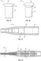
- one or more septum stoppers 10 may help secure a septum 12 within a catheter adapter 14 of a catheter assembly 16.
- the septum 12 may include a blood control septum.
- the septum stoppers 10 may include a variety of shapes and sizes.
- each of the septum stoppers 10 may include a cylindrical bottom portion 18 and/or a head 20 protruding outwardly from the bottom portion 18.
- each of the septum stoppers 10 may include a rounded top surface 22.
- each of the septum stoppers 10 may include a convex or concave top surface 22.
- the rounded top surface 22 may match a curvature of an outer surface of the catheter adapter 14 such that there is a smooth transition between the outer surface of the catheter adapter 15 and each of the septum stoppers 10.
- Figures 1D-1E illustrate the catheter assembly 16 in an insertion configuration, with an introducer needle 40 extending through the catheter adapter 14 and beyond a distal end of a catheter 42.
- the septum 12 may include one or more grooves 24.
- the grooves 24 may be annular.
- the grooves 24 may be aligned with one or more slots or stopper holes 26 that extend through a wall 28 of the catheter adapter 14.
- each of the stopper holes 26 may be sized and configured to secure a particular septum stopper 10.
- each of the stopper holes 26 may include an inner portion corresponding to a size and shape of the bottom portion 18 and/or an outer portion corresponding to a size and shape of the head 20.
- the septum stoppers 10 may extend through the stopper holes 26 such that ends of each of the septum stopper 10 are disposed in the grooves 24, securing the septum 12 within the catheter adapter 14.
- an adhesive 29 may be applied to one or more of the following: the stopper holes 26, the septum stoppers 10, and the grooves 24.
- the catheter adapter 14 may include a first stopper hole 26 and a second stopper hole 26, as illustrated in Figure 1C , for example.
- the first stopper hole 26 and the second stopper hole 26 may be opposing and disposed on opposite sides of the catheter adapter 14.
- the catheter assembly 16 may include any number of septum stoppers 10 and corresponding stopper holes 26.
- the catheter adapter 14 may include three or four stopper holes 26 and septum stoppers 10.
- the stopper holes 26 may be spaced around a circumference of the catheter adapter 14 and/or aligned with a single annular groove 24. In some embodiments, the stopper holes 26 may be disposed at any location around the septum 12.
- the septum 12 may be integrally formed. In some embodiments, the septum 12 may include multiple pieces or components. In some embodiments, a particular groove 24 may be formed at an intersection of the components.
- Suitable materials for the septum stoppers 10 and/or the catheter adapter 14 may include, but are not limited to, thermoplastic polymeric resins such as polycarbonate, polystyrene, polypropylene, polycarbonate, polyethylene terephthalate glycol (PETG), copolyester, and the like. Suitable materials for the septum stoppers 10 and/or the catheter adapter 14 may include, but are not limited to, metals such as steel, zinc, nickel, silver, and the like.
- the septum 12 may be placed within a lumen 30 of the catheter adapter 14 such that grooves 24 of the septum 12 are aligned with the stopper holes 26 extending through the wall 28 of the catheter adapter 14.
- the septum stoppers 10 may then be placed within the stopper holes 26, the ends of the septum stoppers 10 fitting securely within the grooves 24 to secure the septum 12 to the catheter adapter 14.
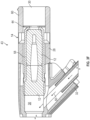
- one or more stopper holes 26 may be disposed proximal to the septum 12, and the septum stoppers 10 disposed within the stopper holes 26 may extend into the lumen 30 proximate the proximal end of the septum 12, as illustrated in Figure 1F .
- the septum stoppers 10 may contact or be slightly spaced apart from the proximal end of the septum 12.
- the septum stoppers 10 may prevent the septum 12 from being dislodged from the catheter adapter 14.
- the high pressure may be 2068.42 kPa (300 psi) or greater.
- the catheter assembly may include an intravenous (IV) catheter.
- the catheter assembly 16 may be integrated or non-integrated. It is understood that the septum stoppers 10 may be used in various types of catheter assemblies, vascular access devices, and with various types of septa.
- the catheter assembly 16 may correspond to the BD INTIMA II TM IV Catheter, the BD NEXIVA TM DIFFUSICS TM Closed IV Catheter System, or another catheter assembly.
- a catheter assembly 33 may include a clip or washer 34 to secure the septum 12.
- the catheter assembly 33 may include or correspond to the catheter assembly 16 of Figure 1 .
- the washer 34 may be U-shaped.
- arms 36 of the washer 34 may be generally parallel to each other.
- Suitable materials for the washer 34 and/or the catheter adapter 14 may include, but are not limited to, thermoplastic polymeric resins such as polycarbonate, polystyrene, polypropylene, polycarbonate, polyethylene terephthalate glycol (PETG), copolyester, and the like.
- Suitable materials for the washer 34 and/or the catheter adapter 14 may include, but are not limited to, metals such as steel, zinc, nickel, silver, and the like.
- the catheter adapter 14 may include two holes 38, which may extend through the wall 28 of the catheter adapter 14.
- each of the holes 38 may be sized and configured to receive an end of a particular arm 36 of the washer 34.
- an inner wall forming the lumen 30 of the catheter adapter may include two grooves, which may each be sized and configured to receive the end of the particular arm 36 of the washer 34.
- the adhesive 29 may be applied to one or more of the ends of the arms 36 and/or the holes 38 or grooves.
- the washer 34 may be disposed within the lumen 30 of the catheter adapter 14 proximal to the proximal end of the septum 12. In some embodiments, the washer 34 may be disposed within the lumen 30 of the catheter adapter 14 in contact with the proximal end of the septum 12 or spaced apart from the proximal end of the septum 12. In some embodiments, the washer 34 may contact and/or apply pressure to the proximal end of the septum 12 in response to the septum 12 being forced proximally, which may occur in response to pressurization, such as, for example, infusion of fluid at the high pressure.
- the introducer needle 40 may extend through a central portion of the washer 34, between the two arms 36. As illustrated in Figure 2D , in some embodiments, the needle 40 may be spaced apart from the washer 34 when the needle 40 extends through the central portion of the washer 34. In some embodiments, when the catheter assembly 33 is in the insertion configuration, the needle 40 may also extend through the septum 12 and extend from a distal end of the catheter 42 coupled to the catheter adapter 14.
- the catheter assembly 33 when the catheter 42 is placed within the vasculature, the catheter assembly 33 may be moved to a fluid delivery configuration in which the needle 40 is retracted, and fluid may be delivered to the vasculature of the patient through the catheter 42.
- the power injector may be coupled to the port 32, and fluid may flow into the catheter adapter 14 via the port 32.
- the arms 36 of the washer 34 may be disposed in the holes 38 and the washer 34 secured within the lumen 30 in both the fluid delivery configuration and the insertion configuration.
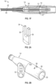
- one or more of the arms 36 of the washer 34 may terminate in a pointed or sharp element 39 that may pierce the septum 12 to facilitate securement of the septum 12.
- the sharp elements 39 may be pin-shaped, as illustrated in Figure 2A .
- the sharp elements 39 may be configured to pierce the septum 12 to secure the washer 34 to the septum 12.
- the sharp elements 39 may allow the septum 12 to be placed less accurately, because the sharp elements 39 may be disposed at various points along a length of the septum 12 and still secure the septum 12 at the high pressure.
- the septum 12 may be constructed of a resilient, flexible material, which may facilitate piercing of the septum 12 by the sharp elements 39.
- the septum 12 may be constructed of silicon, polyisoprene, rubber, an elastomeric polymer, or another material.
- the wall 28 of the catheter adapter 14 may include one or more apertures 41 that allow insertion of the washer 34 into the septum 12.
- a curvature of an outer portion of the washer 34 may match a curvature of an outer surface of the wall 34 such that a smooth transition is provided across an outer surface of the catheter adapter 14.
- a catheter assembly 43 may include another type of washer 44 to secure the septum 12.
- the catheter assembly 43 may include or correspond to the catheter assembly 16 of Figure 1 and/or the catheter assembly 33 of Figure 2 .
- the washer 44 may be positioned within the lumen 30 of the catheter adapter 14 proximal to the septum 12.
- the washer 44 may be conical or domed-shaped in a relaxed state.
- an inner circumference or inner margin 46 of the washer may be distal to an outer circumference or outer margin 48 of the washer 44.
- the washer 44 may be disposed in the relaxed state prior to pressure being applied to the septum 12, such as, for example, through infusion of fluid 50 into the catheter adapter 14.
- the pressure may correspond to the high pressure or greater than or equal to 2068.42 kPa (300 psi).
- the outer margin 48 of the washer 44 may contact the wall 28 of the catheter adapter 14, but a force exerted by the washer 44 on the wall 28 of the catheter adapter 14 may be nominal or low. In some embodiments, the nominal or low pressure may increase a shelf-life of the catheter assembly 43.
- the washer 44 may contact the septum 12 or a space may be disposed between the septum 12 and the washer 34.
- the septum 12 may contact and/or apply pressure to the washer 44 in a proximal direction, which may cause the washer 44 to compress or flatten in a stressed state.
- the washer 44 may lose some or all of its conical or dome shape. In some embodiments, the compression may or may not be visible to the naked eye.
- compressing the washer 44 may increase a diameter of the washer 44 and cause the washer 44 to exert a greater force on the wall 28 of the catheter adapter 14, resulting in the washer 44 being held more securely within the catheter adapter 14 when the pressure is applied to the septum 12.
- the washer 34 may be spring-like or resilient. In some embodiments, when the pressure is no longer applied to the septum 12, the washer 34 may automatically return to an original conical or dome shape and apply less force to the wall 28 of the catheter adapter 14.
- Suitable materials for the washer 44 may include, but are not limited to, thermoplastic polymeric resins such as polycarbonate, polystyrene, polypropylene, polycarbonate, polyethylene terephthalate glycol (PETG), copolyester, and the like.
- Suitable materials for the washer 44 may include, but are not limited to, metals such as steel, zinc, nickel, silver, and the like.
- the outer margin 48 of the washer 44 may include one or more inwardly-extending slots 54. Additionally or alternatively, in some embodiments, the inner margin 46 of the washer 44 may include one or more outwardly-extending slots 56. In some embodiments, the slots 54 and/or the slots 56 may facilitate compression or flattening of the washer 44 in response to the septum 12 applying force to the dome shape of the washer 44. When the washer 44 is compressed, the inner margin 46 may move closed to the outer margin 48. In some embodiments, the washer 44 may secure the septum 12 within the lumen 30 of the catheter adapter 14 in response to increased pressure, due to, for example, infusion, without use of adhesive, welding, or other securement mechanisms.
- the inner margin 46 may define an aperture 59 of the washer 44, which may be centrally located and through which the introducer needle 40 may extend when the catheter assembly 43 is in the insertion configuration.
- an outer diameter of the needle 40 may be less than a diameter of the inner margin 46.
- FIG. 3A An example relaxed state of the washer 44 is illustrated in Figures 3A and Figures 3C-3D .
- An example stressed state of the washer 44 is illustrated in Figure 3B .
- the washer 44 may be disposed in the relaxed state when the catheter assembly 43 is in the insertion configuration.
- the washer 44 may be disposed in the stressed state when a needle assembly 60 is removed, the catheter assembly 43 is in the fluid delivery configuration, and fluid flows into the catheter adapter 14, exerting a proximal force on the septum 12.
- the fluid 50 may force the septum 12 proximally against the washer 44.
- the inner margin 46 may move toward the outer margin 48 in response to the septum being forced proximally against the washer 44, and the outer margin 48 may remain stationary and in contact with the wall 28.
- the catheter assembly 43 may include any suitable type of septum 12.
- the septum 12 may be disposed in a holder or canister 58, which may contact and apply a proximal force to the washer 44 to compress the washer 44, similar to the septum 12 as discussed with respect to Figures 3A-3D .
- the canister 58 may contact and apply a proximal force to the washer 34, similar to the septum 12 as discussed with respect to Figures 2A-2D .
- the septum 12 may include a low-drag septum 12.
- the septum stoppers 10 may extend through the wall 28 and into or through the canister 58, similar to as disclosed with respect to Figures 1A-1D .
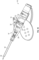
- a proximal end of the needle assembly 60 of a catheter assembly 61 may include a retention disc 62, which may be configured to secure the septum 12 disposed within the catheter adapter 14.
- the catheter assembly 61 may include or correspond to one or more of the following: the catheter assembly 16 of Figure 1 , the catheter assembly 33 of Figure 2 , or the catheter assembly 43 of Figure 3 .
- the retention disc 62 may be connected to a portion of the needle assembly 60 by one or more breakable arms 64.
- the portion of the needle assembly 60 may include a needle hub 66 of the needle assembly 60.
- the arms 64 may extend between the retention disc 62 and the needle hub 66.
- a proximal end of the needle 40 may be secured within the needle hub 66.
- any number of arms 64 may extend between the retention disc 62 and the portion of the needle assembly 60.
- a first arm 64a and a second arm 64b (which may be referred to in the present disclosure as "arms") may be disposed on opposite sides of the needle assembly 60.
- the needle assembly 60 may be molded with a line of weakness 68 extending through the arms 64.
- the line of weakness 68 may include indented or thinner portions of the arms 64.
- the retention disc 62 may include a coupling mechanism for coupling the retention disc 62 to the wall 28 of the catheter adapter 14.
- the coupling mechanism may include any suitable coupling mechanism.
- the retention disc 62 may include one or more wings 70, which may be sized and configured to snap into or interfere with a corresponding groove or opening 72 in the wall 28.
- the retention disc 62 may include a first wing 70a and a second wing 70b.
- the retention disc 62 may include one or more threads that may correspond to one or more threads of the wall 28 of the catheter adapter 14.
- the needle assembly 60 and the retention disc 62 may be inserted into a proximal end of the catheter adapter 14 and coupled to the catheter adapter 14 via the coupling mechanism.
- the needle assembly 60 may be inserted into a proximal end of the catheter adapter 14 such that the wings 70 of the retention disc 62 are aligned with the openings 72 or grooves in the wall 28.
- the retention disc 62 and the needle assembly 60 may be secured within the catheter adapter 14.
- a proximal portion of the needle assembly 60 may be twisted or rotated with respect to the catheter adapter 14, which may cause the arms 64 to break along the line of weakness 68.
- the proximal portion of the needle assembly 60 may be separated from the catheter adapter 14 and the retention disc 62, which may remain secured to the catheter adapter 14.
- the retention disc 62 may retain or secure the septum 12 within the catheter adapter 14 in response to increased pressure, due to, for example, infusion.
- the increased pressure may be 2068.42 kPa (300 psi) or greater.
- the retention disc 62 may contact and/or apply pressure to a proximal end of the septum 12 or a canister 58 of the septum 12 in response to the increased pressure.
- the retention disc 62 may prevent the septum 12 from becoming dislodged or exiting a proximal end of the catheter adapter 14 in the fluid configuration.
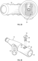
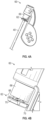
- Figure 4D is an enlarged lower perspective view of the retention disc 62 separated from the proximal portion of the needle assembly 60, according to some embodiments, for illustrative purposes.
- Figure 4E is a cross-sectional view of the catheter assembly 61, across line 4E-4E of Figure 4C , according to some embodiments.
- Figure 4E illustrates the catheter assembly 61 in the fluid delivery configuration, after the needle 40 has been withdrawn proximally through the septum 12.
- the retention disc 62 may be ring-shaped and/or include a central aperture through which the needle 40 may extend.
- the present invention may be embodied in other specific forms without departing from its structures, methods, or other essential characteristics as broadly described herein and claimed hereinafter.
- the catheter assemblies discussed with respect to Figures 1-4 may include additional elements and/or components.
- the catheter assemblies discussed with respect to Figures 1-4 may include various types of needle safety mechanisms.
- the septum stoppers 10, the washer 34, the washer 44, and the retention disc 62 may be used in various types of catheter assemblies, vascular access devices, and with various types of septa.
- the described embodiments and examples are to be considered in all respects only as illustrative, and not restrictive. The scope of the invention is, therefore, indicated by the appended claims, rather than by the foregoing description. All changes that come within the meaning and range of equivalency of the claims are to be embraced within their scope.
Landscapes
- Health & Medical Sciences (AREA)
- Life Sciences & Earth Sciences (AREA)
- Heart & Thoracic Surgery (AREA)
- General Health & Medical Sciences (AREA)
- Veterinary Medicine (AREA)
- Public Health (AREA)
- Engineering & Computer Science (AREA)
- Biomedical Technology (AREA)
- Hematology (AREA)
- Animal Behavior & Ethology (AREA)
- Anesthesiology (AREA)
- Pulmonology (AREA)
- Biophysics (AREA)
- Physics & Mathematics (AREA)
- Pathology (AREA)
- Medical Informatics (AREA)
- Molecular Biology (AREA)
- Surgery (AREA)
- Vascular Medicine (AREA)
- Infusion, Injection, And Reservoir Apparatuses (AREA)
- Media Introduction/Drainage Providing Device (AREA)
Claims (5)
- Katheteranordnung (61) mit:einem Katheteradapter (14) mit einem proximalen Ende, einem distalen Ende, und einem sich zwischen diesen erstreckenden Lumen, wobei das distale Ende einen Katheter aufweist, der zum Einführen in das Gefäßsystem eines Patienten ausgebildet ist;einem in dem Lumen angeordneten Septum (12); undeiner mit dem Katheteradapter (14) verbundenen Nadelanordnung,dadurch gekennzeichnet,dass ein distales Ende der Nadelanordnung mehrere Arme (64) und eine mit den mehreren Armen (64) verbundene Rückhaltescheibe (62) aufweist, wobei die Rückhaltescheibe (62) proximal des Septums (12) in dem Lumen befestigt ist, wobei jeder der mehreren Arme (64) eine Schwächungslinie (68) aufweist, wobei in Reaktion auf das Drehen eines proximalen Endes der Nadelanordnung (60) in Bezug auf den Nadeladapter (14) jeder der mehreren Arme (64) dazu ausgebildet ist, an der Schwächungslinie (68) zu brechen, die Rückhaltescheibe (62) in dem Katheteradapter (14) befestigt bleibt, und das proximale Ende der Nadelanordnung (60) von dem Katheteradapter (14) getrennt wird.
- Katheteranordnung (61) nach Anspruch 1, bei welcher die Rückhaltescheibe (62) einen oder mehr Flügel (70) aufweist, wobei eine Wand des Katheteradapters (14) eine oder mehr Nuten (72) oder Schlitze aufweist, wobei der eine oder die mehreren Flügel (70) in Schnappverbindung in die eine oder die mehreren Nuten (72) oder Schlitze eingreifen.
- Katheteranordnung (61) nach Anspruch 1, bei welcher die Rückhaltescheibe (62) und eine Wand des Katheteradapters (14) korrespondierende Gewinde aufweisen.
- Katheteranordnung (61) nach Anspruch 1, bei welcher die Schwächungslinie (68) einen eingezogenen Bereich aufweist.
- Katheteranordnung (61) nach Anspruch 1, bei welcher die Rückhaltescheibe (62) ringförmig ist und eine Öffnung aufweist, durch welche sich eine Einführnadel der Nadelanordnung (60) erstrecken kann.
Priority Applications (1)
| Application Number | Priority Date | Filing Date | Title |
|---|---|---|---|
| EP24157878.0A EP4344725A3 (de) | 2017-06-08 | 2018-05-29 | Septumbefestigung |
Applications Claiming Priority (2)
| Application Number | Priority Date | Filing Date | Title |
|---|---|---|---|
| US15/617,646 US10512755B2 (en) | 2017-06-08 | 2017-06-08 | Septum securement |
| PCT/US2018/034899 WO2018226453A2 (en) | 2017-06-08 | 2018-05-29 | Septum securement |
Related Child Applications (2)
| Application Number | Title | Priority Date | Filing Date |
|---|---|---|---|
| EP24157878.0A Division-Into EP4344725A3 (de) | 2017-06-08 | 2018-05-29 | Septumbefestigung |
| EP24157878.0A Division EP4344725A3 (de) | 2017-06-08 | 2018-05-29 | Septumbefestigung |
Publications (3)
| Publication Number | Publication Date |
|---|---|
| EP3634560A2 EP3634560A2 (de) | 2020-04-15 |
| EP3634560C0 EP3634560C0 (de) | 2024-04-03 |
| EP3634560B1 true EP3634560B1 (de) | 2024-04-03 |
Family
ID=62683448
Family Applications (2)
| Application Number | Title | Priority Date | Filing Date |
|---|---|---|---|
| EP18732555.0A Active EP3634560B1 (de) | 2017-06-08 | 2018-05-29 | Septumfixierung |
| EP24157878.0A Pending EP4344725A3 (de) | 2017-06-08 | 2018-05-29 | Septumbefestigung |
Family Applications After (1)
| Application Number | Title | Priority Date | Filing Date |
|---|---|---|---|
| EP24157878.0A Pending EP4344725A3 (de) | 2017-06-08 | 2018-05-29 | Septumbefestigung |
Country Status (9)
| Country | Link |
|---|---|
| US (2) | US10512755B2 (de) |
| EP (2) | EP3634560B1 (de) |
| JP (2) | JP7065891B2 (de) |
| CN (2) | CN110913939B (de) |
| AU (1) | AU2018282000B2 (de) |
| CA (1) | CA3065192A1 (de) |
| MX (1) | MX2019014358A (de) |
| SG (1) | SG10202105340VA (de) |
| WO (1) | WO2018226453A2 (de) |
Families Citing this family (9)
| Publication number | Priority date | Publication date | Assignee | Title |
|---|---|---|---|---|
| EP4059556A1 (de) | 2017-03-21 | 2022-09-21 | Velano Vascular, Inc. | Verfahren zur steuerung der grösse einer kathetervorrichtung |
| SG11201907120QA (en) | 2017-03-21 | 2019-10-30 | Velano Vascular Inc | Devices and methods for fluid transfer through a placed peripheral intravenous catheter |
| US10512755B2 (en) * | 2017-06-08 | 2019-12-24 | Becton, Dickinson And Company | Septum securement |
| JP7264819B2 (ja) | 2017-09-29 | 2023-04-25 | テルモ株式会社 | カテーテル組立体 |
| JP7387717B2 (ja) | 2019-03-28 | 2023-11-28 | テルモ株式会社 | カテーテル組立体 |
| KR102881562B1 (ko) | 2019-08-20 | 2025-11-04 | 벨라노 바스큘라, 인크. | 연장된 길이의 카테터를 가진 유체 이송 장치 및 이를 사용하는 방법 |
| US20210299429A1 (en) * | 2020-03-31 | 2021-09-30 | Becton, Dickinson And Company | Catheter assembly with a slidable septum and related systems and methods |
| JP2024504631A (ja) * | 2021-01-15 | 2024-02-01 | ベクトン・ディキンソン・アンド・カンパニー | 採血アセンブリおよび関連するデバイスおよび方法 |
| MX2023013451A (es) * | 2021-05-14 | 2023-12-15 | Becton Dickinson Co | Conjunto de cateter y dispositivos y metodos relacionados. |
Family Cites Families (28)
| Publication number | Priority date | Publication date | Assignee | Title |
|---|---|---|---|---|
| US4929235A (en) | 1985-07-31 | 1990-05-29 | Universal Medical Instrument Corp. | Self-sealing percutaneous tube introducer |
| US5000745A (en) * | 1988-11-18 | 1991-03-19 | Edward Weck Incorporated | Hemostatis valve |
| US6632200B2 (en) | 2000-01-25 | 2003-10-14 | St. Jude Medical, Daig Division | Hemostasis valve |
| US6506181B2 (en) | 2001-05-25 | 2003-01-14 | Becton, Dickinson And Company | Catheter having a low drag septum |
| US7347853B2 (en) * | 2004-05-12 | 2008-03-25 | C. R. Bard, Inc. | Catheter with removable extension |
| WO2006127123A2 (en) * | 2005-05-20 | 2006-11-30 | Medtronic, Inc. | Locking catheter connector and method |
| AU2006302049B2 (en) * | 2005-10-11 | 2012-06-07 | Cardinal Health 529, Llc | IV catheter with in-line valve and methods related thereto |
| US7670317B2 (en) | 2005-10-25 | 2010-03-02 | Becton, Dickinson And Company | One piece low drag septum |
| US20080249475A1 (en) * | 2006-02-22 | 2008-10-09 | Applied Medical Resources Corporation | Trocar seal |
| US8257313B2 (en) * | 2006-08-11 | 2012-09-04 | Becton, Dickinson And Company | Integrated septum and needle tip shield for a catheter assembly |
| JP5283626B2 (ja) * | 2007-09-27 | 2013-09-04 | テルモ株式会社 | 弁体および医療用具 |
| US9101748B2 (en) * | 2008-05-08 | 2015-08-11 | Becton, Dickinson And Company | Push-button blood control |
| US8679063B2 (en) * | 2009-02-11 | 2014-03-25 | Becton, Dickinson And Company | Systems and methods for providing a catheter assembly |
| US8597252B2 (en) | 2010-07-15 | 2013-12-03 | Becton, Dickinson And Company | Removable flash chamber |
| US8932259B2 (en) * | 2010-09-13 | 2015-01-13 | Becton, Dickinson And Company | Catheter assembly |
| AU2013206101A1 (en) * | 2011-03-08 | 2013-06-20 | Covidien Lp | Catheter with valve |
| US9358364B2 (en) | 2011-10-06 | 2016-06-07 | Becton, Dickinson And Company | Activator attachment for blood control catheters |
| CN202620440U (zh) | 2012-03-02 | 2012-12-26 | 碧迪控股有限公司 | 导管和插管器针组件 |
| WO2013142386A1 (en) * | 2012-03-18 | 2013-09-26 | Avneri Itzhak | Devices and methods for endovascular access and therapy |
| JP6083850B2 (ja) * | 2012-08-24 | 2017-02-22 | 株式会社グッドマン | 医療用弁装置 |
| US10500376B2 (en) | 2013-06-07 | 2019-12-10 | Becton, Dickinson And Company | IV catheter having external needle shield and internal blood control septum |
| JP2015019546A (ja) * | 2013-07-12 | 2015-01-29 | 株式会社東芝 | アキシャルギャップ型永久磁石回転電機およびその製造方法 |
| US9919136B2 (en) | 2013-12-04 | 2018-03-20 | B. Braun Melsungen Ag | Catheter assembly with reusable valve |
| CN103736195B (zh) * | 2014-01-13 | 2018-07-03 | 厦门鑫康顺医疗科技有限公司 | 一种无菌导管鞘 |
| US9895525B2 (en) * | 2014-01-21 | 2018-02-20 | Becton, Dickinson And Company | Ported catheter adapter with integrated septum actuator retention |
| US9987477B2 (en) * | 2014-02-10 | 2018-06-05 | Nexus Medical, Llc | Split septum assembly for an intravenous injection site |
| US9931489B2 (en) | 2015-05-12 | 2018-04-03 | Medtronic Vascular, Inc. | Cross slit gasket for introducer sheath |
| US10512755B2 (en) * | 2017-06-08 | 2019-12-24 | Becton, Dickinson And Company | Septum securement |
-
2017
- 2017-06-08 US US15/617,646 patent/US10512755B2/en active Active
-
2018
- 2018-05-29 CN CN201880047740.7A patent/CN110913939B/zh active Active
- 2018-05-29 EP EP18732555.0A patent/EP3634560B1/de active Active
- 2018-05-29 CN CN202210052100.3A patent/CN114377248B/zh active Active
- 2018-05-29 SG SG10202105340VA patent/SG10202105340VA/en unknown
- 2018-05-29 MX MX2019014358A patent/MX2019014358A/es unknown
- 2018-05-29 WO PCT/US2018/034899 patent/WO2018226453A2/en not_active Ceased
- 2018-05-29 AU AU2018282000A patent/AU2018282000B2/en active Active
- 2018-05-29 JP JP2019568086A patent/JP7065891B2/ja active Active
- 2018-05-29 CA CA3065192A patent/CA3065192A1/en active Pending
- 2018-05-29 EP EP24157878.0A patent/EP4344725A3/de active Pending
-
2019
- 2019-11-18 US US16/687,341 patent/US11628273B2/en active Active
-
2022
- 2022-02-08 JP JP2022017969A patent/JP7325559B2/ja active Active
Also Published As
| Publication number | Publication date |
|---|---|
| JP2020523108A (ja) | 2020-08-06 |
| WO2018226453A3 (en) | 2019-01-17 |
| US11628273B2 (en) | 2023-04-18 |
| CN110913939B (zh) | 2022-02-11 |
| JP7065891B2 (ja) | 2022-05-12 |
| EP3634560C0 (de) | 2024-04-03 |
| CA3065192A1 (en) | 2018-12-13 |
| JP2022051879A (ja) | 2022-04-01 |
| JP7325559B2 (ja) | 2023-08-14 |
| CN114377248B (zh) | 2024-09-03 |
| BR112019025936A2 (pt) | 2020-06-30 |
| EP3634560A2 (de) | 2020-04-15 |
| WO2018226453A2 (en) | 2018-12-13 |
| US10512755B2 (en) | 2019-12-24 |
| NZ759821A (en) | 2025-05-02 |
| US20180353729A1 (en) | 2018-12-13 |
| AU2018282000B2 (en) | 2023-10-05 |
| MX2019014358A (es) | 2020-01-23 |
| EP4344725A3 (de) | 2024-07-10 |
| CN110913939A (zh) | 2020-03-24 |
| CN114377248A (zh) | 2022-04-22 |
| EP4344725A2 (de) | 2024-04-03 |
| AU2018282000A1 (en) | 2020-01-02 |
| US20200078556A1 (en) | 2020-03-12 |
| SG10202105340VA (en) | 2021-07-29 |
Similar Documents
| Publication | Publication Date | Title |
|---|---|---|
| EP3634560B1 (de) | Septumfixierung | |
| AU2022271462B2 (en) | Septum housing for a catheter | |
| EP3305352B1 (de) | Infusionsvorrichtung mit einem abnehmbaren fluidstecker | |
| US7247148B2 (en) | Protector and storage needle assembly | |
| ES2661016T3 (es) | Característica de retención para una conexión de interfaz blanda | |
| EP3632502B1 (de) | Rotationsaktivierte blutkontrolle | |
| JPH0532071B2 (de) | ||
| KR102588907B1 (ko) | 약물 전달 장치에 커넥터를 연결하기 위한 어댑터 | |
| BR112019025936B1 (pt) | Montagens de cateter |
Legal Events
| Date | Code | Title | Description |
|---|---|---|---|
| STAA | Information on the status of an ep patent application or granted ep patent |
Free format text: STATUS: UNKNOWN |
|
| STAA | Information on the status of an ep patent application or granted ep patent |
Free format text: STATUS: THE INTERNATIONAL PUBLICATION HAS BEEN MADE |
|
| PUAI | Public reference made under article 153(3) epc to a published international application that has entered the european phase |
Free format text: ORIGINAL CODE: 0009012 |
|
| STAA | Information on the status of an ep patent application or granted ep patent |
Free format text: STATUS: REQUEST FOR EXAMINATION WAS MADE |
|
| 17P | Request for examination filed |
Effective date: 20200106 |
|
| AK | Designated contracting states |
Kind code of ref document: A2 Designated state(s): AL AT BE BG CH CY CZ DE DK EE ES FI FR GB GR HR HU IE IS IT LI LT LU LV MC MK MT NL NO PL PT RO RS SE SI SK SM TR |
|
| AX | Request for extension of the european patent |
Extension state: BA ME |
|
| DAV | Request for validation of the european patent (deleted) | ||
| DAX | Request for extension of the european patent (deleted) | ||
| STAA | Information on the status of an ep patent application or granted ep patent |
Free format text: STATUS: EXAMINATION IS IN PROGRESS |
|
| 17Q | First examination report despatched |
Effective date: 20230213 |
|
| REG | Reference to a national code |
Ref country code: DE Ref legal event code: R079 Free format text: PREVIOUS MAIN CLASS: A61M0025000000 Ipc: A61M0025060000 Ref country code: DE Ref legal event code: R079 Ref document number: 602018067477 Country of ref document: DE Free format text: PREVIOUS MAIN CLASS: A61M0025000000 Ipc: A61M0025060000 |
|
| RIC1 | Information provided on ipc code assigned before grant |
Ipc: A61M 39/00 20060101ALI20230929BHEP Ipc: A61M 25/00 20060101ALI20230929BHEP Ipc: A61M 39/06 20060101ALI20230929BHEP Ipc: A61M 25/06 20060101AFI20230929BHEP |
|
| GRAP | Despatch of communication of intention to grant a patent |
Free format text: ORIGINAL CODE: EPIDOSNIGR1 |
|
| STAA | Information on the status of an ep patent application or granted ep patent |
Free format text: STATUS: GRANT OF PATENT IS INTENDED |
|
| INTG | Intention to grant announced |
Effective date: 20231117 |
|
| GRAS | Grant fee paid |
Free format text: ORIGINAL CODE: EPIDOSNIGR3 |
|
| GRAA | (expected) grant |
Free format text: ORIGINAL CODE: 0009210 |
|
| STAA | Information on the status of an ep patent application or granted ep patent |
Free format text: STATUS: THE PATENT HAS BEEN GRANTED |
|
| AK | Designated contracting states |
Kind code of ref document: B1 Designated state(s): AL AT BE BG CH CY CZ DE DK EE ES FI FR GB GR HR HU IE IS IT LI LT LU LV MC MK MT NL NO PL PT RO RS SE SI SK SM TR |
|
| REG | Reference to a national code |
Ref country code: GB Ref legal event code: FG4D |
|
| REG | Reference to a national code |
Ref country code: CH Ref legal event code: EP |
|
| REG | Reference to a national code |
Ref country code: IE Ref legal event code: FG4D |
|
| REG | Reference to a national code |
Ref country code: DE Ref legal event code: R096 Ref document number: 602018067477 Country of ref document: DE |
|
| U01 | Request for unitary effect filed |
Effective date: 20240422 |
|
| U07 | Unitary effect registered |
Designated state(s): AT BE BG DE DK EE FI FR IT LT LU LV MT NL PT SE SI Effective date: 20240426 |
|
| U20 | Renewal fee for the european patent with unitary effect paid |
Year of fee payment: 7 Effective date: 20240507 |
|
| PG25 | Lapsed in a contracting state [announced via postgrant information from national office to epo] |
Ref country code: IS Free format text: LAPSE BECAUSE OF FAILURE TO SUBMIT A TRANSLATION OF THE DESCRIPTION OR TO PAY THE FEE WITHIN THE PRESCRIBED TIME-LIMIT Effective date: 20240803 |
|
| PG25 | Lapsed in a contracting state [announced via postgrant information from national office to epo] |
Ref country code: HR Free format text: LAPSE BECAUSE OF FAILURE TO SUBMIT A TRANSLATION OF THE DESCRIPTION OR TO PAY THE FEE WITHIN THE PRESCRIBED TIME-LIMIT Effective date: 20240403 |
|
| PG25 | Lapsed in a contracting state [announced via postgrant information from national office to epo] |
Ref country code: GR Free format text: LAPSE BECAUSE OF FAILURE TO SUBMIT A TRANSLATION OF THE DESCRIPTION OR TO PAY THE FEE WITHIN THE PRESCRIBED TIME-LIMIT Effective date: 20240704 |
|
| PG25 | Lapsed in a contracting state [announced via postgrant information from national office to epo] |
Ref country code: ES Free format text: LAPSE BECAUSE OF FAILURE TO SUBMIT A TRANSLATION OF THE DESCRIPTION OR TO PAY THE FEE WITHIN THE PRESCRIBED TIME-LIMIT Effective date: 20240403 |
|
| PG25 | Lapsed in a contracting state [announced via postgrant information from national office to epo] |
Ref country code: CZ Free format text: LAPSE BECAUSE OF FAILURE TO SUBMIT A TRANSLATION OF THE DESCRIPTION OR TO PAY THE FEE WITHIN THE PRESCRIBED TIME-LIMIT Effective date: 20240403 |
|
| PG25 | Lapsed in a contracting state [announced via postgrant information from national office to epo] |
Ref country code: PL Free format text: LAPSE BECAUSE OF FAILURE TO SUBMIT A TRANSLATION OF THE DESCRIPTION OR TO PAY THE FEE WITHIN THE PRESCRIBED TIME-LIMIT Effective date: 20240403 |
|
| PG25 | Lapsed in a contracting state [announced via postgrant information from national office to epo] |
Ref country code: PL Free format text: LAPSE BECAUSE OF FAILURE TO SUBMIT A TRANSLATION OF THE DESCRIPTION OR TO PAY THE FEE WITHIN THE PRESCRIBED TIME-LIMIT Effective date: 20240403 Ref country code: NO Free format text: LAPSE BECAUSE OF FAILURE TO SUBMIT A TRANSLATION OF THE DESCRIPTION OR TO PAY THE FEE WITHIN THE PRESCRIBED TIME-LIMIT Effective date: 20240703 Ref country code: IS Free format text: LAPSE BECAUSE OF FAILURE TO SUBMIT A TRANSLATION OF THE DESCRIPTION OR TO PAY THE FEE WITHIN THE PRESCRIBED TIME-LIMIT Effective date: 20240803 Ref country code: HR Free format text: LAPSE BECAUSE OF FAILURE TO SUBMIT A TRANSLATION OF THE DESCRIPTION OR TO PAY THE FEE WITHIN THE PRESCRIBED TIME-LIMIT Effective date: 20240403 Ref country code: GR Free format text: LAPSE BECAUSE OF FAILURE TO SUBMIT A TRANSLATION OF THE DESCRIPTION OR TO PAY THE FEE WITHIN THE PRESCRIBED TIME-LIMIT Effective date: 20240704 Ref country code: ES Free format text: LAPSE BECAUSE OF FAILURE TO SUBMIT A TRANSLATION OF THE DESCRIPTION OR TO PAY THE FEE WITHIN THE PRESCRIBED TIME-LIMIT Effective date: 20240403 Ref country code: CZ Free format text: LAPSE BECAUSE OF FAILURE TO SUBMIT A TRANSLATION OF THE DESCRIPTION OR TO PAY THE FEE WITHIN THE PRESCRIBED TIME-LIMIT Effective date: 20240403 Ref country code: RS Free format text: LAPSE BECAUSE OF FAILURE TO SUBMIT A TRANSLATION OF THE DESCRIPTION OR TO PAY THE FEE WITHIN THE PRESCRIBED TIME-LIMIT Effective date: 20240703 |
|
| REG | Reference to a national code |
Ref country code: CH Ref legal event code: PL |
|
| REG | Reference to a national code |
Ref country code: DE Ref legal event code: R097 Ref document number: 602018067477 Country of ref document: DE |
|
| PG25 | Lapsed in a contracting state [announced via postgrant information from national office to epo] |
Ref country code: SK Free format text: LAPSE BECAUSE OF FAILURE TO SUBMIT A TRANSLATION OF THE DESCRIPTION OR TO PAY THE FEE WITHIN THE PRESCRIBED TIME-LIMIT Effective date: 20240403 Ref country code: RO Free format text: LAPSE BECAUSE OF FAILURE TO SUBMIT A TRANSLATION OF THE DESCRIPTION OR TO PAY THE FEE WITHIN THE PRESCRIBED TIME-LIMIT Effective date: 20240403 |
|
| PG25 | Lapsed in a contracting state [announced via postgrant information from national office to epo] |
Ref country code: SM Free format text: LAPSE BECAUSE OF FAILURE TO SUBMIT A TRANSLATION OF THE DESCRIPTION OR TO PAY THE FEE WITHIN THE PRESCRIBED TIME-LIMIT Effective date: 20240403 |
|
| PG25 | Lapsed in a contracting state [announced via postgrant information from national office to epo] |
Ref country code: SM Free format text: LAPSE BECAUSE OF FAILURE TO SUBMIT A TRANSLATION OF THE DESCRIPTION OR TO PAY THE FEE WITHIN THE PRESCRIBED TIME-LIMIT Effective date: 20240403 Ref country code: SK Free format text: LAPSE BECAUSE OF FAILURE TO SUBMIT A TRANSLATION OF THE DESCRIPTION OR TO PAY THE FEE WITHIN THE PRESCRIBED TIME-LIMIT Effective date: 20240403 Ref country code: RO Free format text: LAPSE BECAUSE OF FAILURE TO SUBMIT A TRANSLATION OF THE DESCRIPTION OR TO PAY THE FEE WITHIN THE PRESCRIBED TIME-LIMIT Effective date: 20240403 Ref country code: CH Free format text: LAPSE BECAUSE OF NON-PAYMENT OF DUE FEES Effective date: 20240531 Ref country code: MC Free format text: LAPSE BECAUSE OF FAILURE TO SUBMIT A TRANSLATION OF THE DESCRIPTION OR TO PAY THE FEE WITHIN THE PRESCRIBED TIME-LIMIT Effective date: 20240403 |
|
| PLBE | No opposition filed within time limit |
Free format text: ORIGINAL CODE: 0009261 |
|
| STAA | Information on the status of an ep patent application or granted ep patent |
Free format text: STATUS: NO OPPOSITION FILED WITHIN TIME LIMIT |
|
| 26N | No opposition filed |
Effective date: 20250106 |
|
| PG25 | Lapsed in a contracting state [announced via postgrant information from national office to epo] |
Ref country code: IE Free format text: LAPSE BECAUSE OF NON-PAYMENT OF DUE FEES Effective date: 20240529 |
|
| U20 | Renewal fee for the european patent with unitary effect paid |
Year of fee payment: 8 Effective date: 20250423 |
|
| PGFP | Annual fee paid to national office [announced via postgrant information from national office to epo] |
Ref country code: GB Payment date: 20250423 Year of fee payment: 8 |
|
| PG25 | Lapsed in a contracting state [announced via postgrant information from national office to epo] |
Ref country code: CY Free format text: LAPSE BECAUSE OF FAILURE TO SUBMIT A TRANSLATION OF THE DESCRIPTION OR TO PAY THE FEE WITHIN THE PRESCRIBED TIME-LIMIT; INVALID AB INITIO Effective date: 20180529 |
|
| PG25 | Lapsed in a contracting state [announced via postgrant information from national office to epo] |
Ref country code: HU Free format text: LAPSE BECAUSE OF FAILURE TO SUBMIT A TRANSLATION OF THE DESCRIPTION OR TO PAY THE FEE WITHIN THE PRESCRIBED TIME-LIMIT; INVALID AB INITIO Effective date: 20180529 |