EP3634645B1 - Coupelles en cloche de pulvérisateur rotatif - Google Patents
Coupelles en cloche de pulvérisateur rotatif Download PDFInfo
- Publication number
- EP3634645B1 EP3634645B1 EP18728722.2A EP18728722A EP3634645B1 EP 3634645 B1 EP3634645 B1 EP 3634645B1 EP 18728722 A EP18728722 A EP 18728722A EP 3634645 B1 EP3634645 B1 EP 3634645B1
- Authority
- EP
- European Patent Office
- Prior art keywords
- bell
- hub
- machining
- manufacturing process
- additive manufacturing
- Prior art date
- Legal status (The legal status is an assumption and is not a legal conclusion. Google has not performed a legal analysis and makes no representation as to the accuracy of the status listed.)
- Active
Links
Images
Classifications
-
- B—PERFORMING OPERATIONS; TRANSPORTING
- B05—SPRAYING OR ATOMISING IN GENERAL; APPLYING FLUENT MATERIALS TO SURFACES, IN GENERAL
- B05B—SPRAYING APPARATUS; ATOMISING APPARATUS; NOZZLES
- B05B3/00—Spraying or sprinkling apparatus with moving outlet elements or moving deflecting elements
- B05B3/02—Spraying or sprinkling apparatus with moving outlet elements or moving deflecting elements with rotating elements
- B05B3/10—Spraying or sprinkling apparatus with moving outlet elements or moving deflecting elements with rotating elements discharging over substantially the whole periphery of the rotating member
- B05B3/1007—Spraying or sprinkling apparatus with moving outlet elements or moving deflecting elements with rotating elements discharging over substantially the whole periphery of the rotating member characterised by the rotating member
- B05B3/1014—Spraying or sprinkling apparatus with moving outlet elements or moving deflecting elements with rotating elements discharging over substantially the whole periphery of the rotating member characterised by the rotating member with a spraying edge, e.g. like a cup or a bell
-
- B—PERFORMING OPERATIONS; TRANSPORTING
- B05—SPRAYING OR ATOMISING IN GENERAL; APPLYING FLUENT MATERIALS TO SURFACES, IN GENERAL
- B05B—SPRAYING APPARATUS; ATOMISING APPARATUS; NOZZLES
- B05B5/00—Electrostatic spraying apparatus; Spraying apparatus with means for charging the spray electrically; Apparatus for spraying liquids or other fluent materials by other electric means
- B05B5/025—Discharge apparatus, e.g. electrostatic spray guns
- B05B5/04—Discharge apparatus, e.g. electrostatic spray guns characterised by having rotary outlet or deflecting elements, i.e. spraying being also effected by centrifugal forces
- B05B5/0403—Discharge apparatus, e.g. electrostatic spray guns characterised by having rotary outlet or deflecting elements, i.e. spraying being also effected by centrifugal forces characterised by the rotating member
- B05B5/0407—Discharge apparatus, e.g. electrostatic spray guns characterised by having rotary outlet or deflecting elements, i.e. spraying being also effected by centrifugal forces characterised by the rotating member with a spraying edge, e.g. like a cup or a bell
-
- B—PERFORMING OPERATIONS; TRANSPORTING
- B05—SPRAYING OR ATOMISING IN GENERAL; APPLYING FLUENT MATERIALS TO SURFACES, IN GENERAL
- B05B—SPRAYING APPARATUS; ATOMISING APPARATUS; NOZZLES
- B05B5/00—Electrostatic spraying apparatus; Spraying apparatus with means for charging the spray electrically; Apparatus for spraying liquids or other fluent materials by other electric means
- B05B5/025—Discharge apparatus, e.g. electrostatic spray guns
- B05B5/04—Discharge apparatus, e.g. electrostatic spray guns characterised by having rotary outlet or deflecting elements, i.e. spraying being also effected by centrifugal forces
- B05B5/0403—Discharge apparatus, e.g. electrostatic spray guns characterised by having rotary outlet or deflecting elements, i.e. spraying being also effected by centrifugal forces characterised by the rotating member
-
- B—PERFORMING OPERATIONS; TRANSPORTING
- B22—CASTING; POWDER METALLURGY
- B22F—WORKING METALLIC POWDER; MANUFACTURE OF ARTICLES FROM METALLIC POWDER; MAKING METALLIC POWDER; APPARATUS OR DEVICES SPECIALLY ADAPTED FOR METALLIC POWDER
- B22F10/00—Additive manufacturing of workpieces or articles from metallic powder
- B22F10/20—Direct sintering or melting
- B22F10/28—Powder bed fusion, e.g. selective laser melting [SLM] or electron beam melting [EBM]
-
- B—PERFORMING OPERATIONS; TRANSPORTING
- B33—ADDITIVE MANUFACTURING TECHNOLOGY
- B33Y—ADDITIVE MANUFACTURING, i.e. MANUFACTURING OF THREE-DIMENSIONAL [3D] OBJECTS BY ADDITIVE DEPOSITION, ADDITIVE AGGLOMERATION OR ADDITIVE LAYERING, e.g. BY 3D PRINTING, STEREOLITHOGRAPHY OR SELECTIVE LASER SINTERING
- B33Y10/00—Processes of additive manufacturing
-
- B—PERFORMING OPERATIONS; TRANSPORTING
- B33—ADDITIVE MANUFACTURING TECHNOLOGY
- B33Y—ADDITIVE MANUFACTURING, i.e. MANUFACTURING OF THREE-DIMENSIONAL [3D] OBJECTS BY ADDITIVE DEPOSITION, ADDITIVE AGGLOMERATION OR ADDITIVE LAYERING, e.g. BY 3D PRINTING, STEREOLITHOGRAPHY OR SELECTIVE LASER SINTERING
- B33Y80/00—Products made by additive manufacturing
-
- Y—GENERAL TAGGING OF NEW TECHNOLOGICAL DEVELOPMENTS; GENERAL TAGGING OF CROSS-SECTIONAL TECHNOLOGIES SPANNING OVER SEVERAL SECTIONS OF THE IPC; TECHNICAL SUBJECTS COVERED BY FORMER USPC CROSS-REFERENCE ART COLLECTIONS [XRACs] AND DIGESTS
- Y02—TECHNOLOGIES OR APPLICATIONS FOR MITIGATION OR ADAPTATION AGAINST CLIMATE CHANGE
- Y02P—CLIMATE CHANGE MITIGATION TECHNOLOGIES IN THE PRODUCTION OR PROCESSING OF GOODS
- Y02P10/00—Technologies related to metal processing
- Y02P10/25—Process efficiency
-
- Y—GENERAL TAGGING OF NEW TECHNOLOGICAL DEVELOPMENTS; GENERAL TAGGING OF CROSS-SECTIONAL TECHNOLOGIES SPANNING OVER SEVERAL SECTIONS OF THE IPC; TECHNICAL SUBJECTS COVERED BY FORMER USPC CROSS-REFERENCE ART COLLECTIONS [XRACs] AND DIGESTS
- Y10—TECHNICAL SUBJECTS COVERED BY FORMER USPC
- Y10T—TECHNICAL SUBJECTS COVERED BY FORMER US CLASSIFICATION
- Y10T29/00—Metal working
- Y10T29/49—Method of mechanical manufacture
- Y10T29/49428—Gas and water specific plumbing component making
- Y10T29/49432—Nozzle making
- Y10T29/49433—Sprayer
Definitions
- This invention relates to a method of manufacturing rotary atomisers and rotary atomiser bell cups and a method of manufacturing rotary atomiser spindles including such rotary atomiser bell cups.
- Rotary atomisers are used in various situations for coating surfaces.
- One particular use of rotary atomisers is in the field of paint spraying. This, for example, is common in the automotive industry for paint spraying of vehicles.
- a rotary atomiser spindle is mounted on a robot arm and this is moved through space and to different orientations in order to spray paint the vehicle.
- different support arrangements may be provided.
- More generally rotary atomisers are used as a paint applicator in high volume production environments. Also called a 'paint bell', or 'bell applicator', they are preferred for high volume paint application due to superior transfer efficiency, spray pattern consistency, and low compressed air consumption, when compared to paint spray guns.
- a bell cup comprises a conical or curved disc fixed to the shaft of a drive spindle which can for example be driven by a turbine. Paint is injected into the centre of the rear of the disc, and is atomised by being forced out to the edge of the cup by centrifugal forces. The flow of the paint over the cup and off the edge breaks up the paint into atomized droplets.
- the turbine is a high speed, high precision air motor that rotates the bell cup at speeds ranging from 10,000rpm to 70,000rpm, depending on the cup diameter, atomisation desired, and physical properties of the paint.
- Typical turbines for this application use an air bearing, where the spinning shaft is suspended in a cushion of flowing compressed air, with virtually no frictional resistance.
- An electrostatic system is typically provided for ensuring efficient coating of the work-piece.
- the electrostatic system can be internal or external (or direct or indirect charge), and supplies high voltage (say 30,000 to 100,000 volts DC) charge to the applicator, or the air surrounding it. This has the effect of negatively charging the paint, while causing a region of positive charge to form on the work-piece, resulting in electrostatic attraction between the paint and the work-piece.
- a shaping air shroud or shaping air ring. This is simply a ring with passages for air to flow out the front of the atomiser, outside of the cup diameter, to manage the size of the spray pattern produced. As more air is forced through the shroud, the atomised paint is forced into a smaller pattern.
- the bell cup of the rotary atomiser is rotated at high rates of rotation.
- gyroscopic effects become relevant and can have an adverse effect on the operation, accuracy, or lifetime of the spindle or the robotic arm or other support arrangement as a whole.
- DE102016006177 describes a rotary atomizer comprising a bell cup as an application component, in which the bell cup is manufactured by injection molding and, preferably, by an additive manufacturing process for producing the cellular structures.
- JP2007222731 describes a rotary atomizing head used in a bell type coating machine and a method for designing a rotary atomizing head.
- US2009212122 describes an application element for a rotary atomizer in the form of a bell-shaped plate or a rotary disk, and an associated operating method.
- US2003164406 describes a device for spraying a liquid coating product including a hub forming or accommodating a liquid feed pipe and a divergent centrifugal deflector having a distribution surface whose overall shape is that of a trumpet bell.
- DE202007015115U describe a bell for a rotary atomizer, in which the bell body can be formed in two parts by a feed-end body and an annular bell edge part. The two parts can be glued, welded, pressed, latched, screwed or jammed together as desired.
- US 2011/221100 A1 describes a method for producing a painting plant component, such as an atomizer, by a rapid prototyping method.
- K.P. KARUNAKARAN ET AL "Low cost integration of additive and subtractive processes for hybrid layered manufacturing", ROBOTICS AND COMPUTER INTEGRATED MANUFACTURING., GB, (20101001), vol. 26, no. 5 , a process is described in which the near-net shape of the object is first built using weld-deposition; the near-net shape is then finish machined subsequently.
- a method of manufacturing a rotary atomiser bell cup comprising a bell portion for spraying media in use and a hub portion via which the bell portion is rotatingly drivable in use, as claimed in claim 1.
- the bell cup may be machined after the additive manufacturing process. This may be to provide finished dimensions.
- the method may comprise machining the bell cup after the additive manufacturing process. This may be to provide finished dimensions.
- the machining after the additive manufacturing process may comprise removal of material of the bell portion and/or of the hub portion.
- the method may comprise the step of forming a platform portion as part of the hub portion during the initial machining of the hub portion, said platform portion being arranged to facilitate the building up of the bell portion.
- the method may comprise the step of machining away at least a part of the platform portion during machining after the additive manufacturing process.
- the bell portion may be hollow so defining at least one internal void.
- the bell portion may comprise at least one supporting rib provided in said internal void.
- the bell portion may comprise an internal lattice structure provided in said internal void.
- the bell portion may comprise a first outer conical wall portion and a second inner conical wall portion, wherein the internal void is provided therebetween and at least one support element is provided between the inner and outer conical wall portions.
- the at least one support element may, for example, comprise an internal lattice structure and/or at least one supporting rib.
- the bell portion may define at least one aperture providing a fluid communication path between the internal void and the exterior of the bell portion. This path may act as an escape path from the internal void to the exterior of the bell portion. This can allow the escape of byproduct from the additive manufacturing process - for example unfused powder.
- the additive manufacturing process may comprise laser sintering of metallic powder.
- the at least one aperture may allow escape of unsintered metallic powder from the void.
- the internal void may comprise no closed cells to ensure evacuation of unfused powder.
- the void may provide a fluid communication passage through the interior of the bell portion for use in operation as part of a rotary atomiser. This may allow the delivery of a fluid, say a cleaning fluid, to a desired location.
- the bell portion may define at least one fluid delivery aperture for allowing flow of fluid out of the internal void to the exterior of the bell portion.
- the bell portion may comprise at least two apertures providing a fluid communication path between the internal void and the exterior of the bell portion.
- a first of the apertures may act as a fluid inlet and a second of the apertures may act as a fluid outlet during operation of the bell cup as part of a rotary atomiser.
- the hub portion may comprise an interface portion for mounting to a spindle for rotatingly driving the bell cup.
- the hub may be arranged for mounting on a shaft of the spindle.
- the interface portion may also be used for mounting the hub/the bell cup on a tooling shaft for machining before and/or after the additive manufacturing process.
- the interface portion may comprise a datum relative to which machining before and/or after the additive manufacturing process may be conducted.
- a rotary atomiser spindle including a bell cup comprising a bell portion for spraying media in use and a hub portion via which the bell portion is rotatingly drivable by the spindle in use, as claimed in claim 7.
- the spindle may comprise a main body within which is journaled a shaft for rotation relative to the main body.
- the bell cup may be mounted on the shaft via the hub.
- the spindle may comprise one or more radial air bearing in which the shaft is journaled.
- the spindle may comprise a turbine which is mounted on the shaft for rotatingly driving the shaft and hence bell cup.
- the main body may be arranged for feeding drive gas to the turbine.
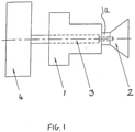
- Figure 1 schematically shows a rotary atomiser in the form of a paint sprayer which comprises a rotary atomiser spindle 1 comprising and arranged for rotatingly driving a paint spraying bell cup 2.
- the spindle 1 comprises a shaft 1a which is journaled in at least one radial air bearing (not shown) and carries a turbine wheel (not shown) for rotational drive of the shaft 1a under action of drive gas.
- the paint sprayer shown in Figure 1 also comprises a supply arrangement 3 for supplying material, i.e. paint in this case, from a reservoir 4 to the bell cup 2 so that this paint may be atomised by the bell cup 2 and projected towards the surface which is to be coated with paint.
- paint is projected towards the surface to be painted by electrostatic force created by a high voltage applied between the spindle 1 and the surface to be painted.
- the structure and operation of the paint sprayer at this level is conventional and such paint sprayers are widely used in the art and well understood. It is the method of manufacturing of the spindle 1 and in particular the bell cup 2 which are of interest in the present invention. These will be described in more detail below.
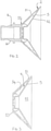
- Figure 2 shows in section the bell cup 2 of the rotary atomiser in more detail.
- the bell cup 2 is shown in a finished condition ready for attachment to the shaft 1a of the spindle 1.
- the bell cup 2 comprises a bell portion 5 and a hub portion 6.
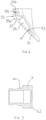
- the bell portion 5 is shown in isolation in Figures 3 and 4 and the hub portion 6 is shown in isolation in Figure 5 .
- the hub portion is generally cylindrical and the bell portion is generally conical.
- the hub portion 6 is a machined metal part whereas the bell portion 5 is formed by an additive manufacturing process in particular by laser sintering of metal powder.
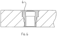
- the hub portion 6 is first machined as an isolated component as shown in Figure 5 .
- the stub portion comprises an interface portion 61 which acts as a datum - in the present case the interface portion is a taper portion 61; in alternatives different forms of interface portion may be used. Machining of the hub portion 6 alone as well as bell cup 2 as a whole is carried out in reference to this datum. When the finished bell cup 2 is mounted to the shaft 1a this taper 61 fits with a corresponding taper (not shown) in the shaft 1a.
- the hub portion 6 When the hub portion 6 is first machined and it is an isolated component as shown in Figure 5 , it comprises a platform portion 62 upon which the bell portion 5 can be built up via the additive manufacturing process providing a good area for fusing between the material (ie metal powder) used in the additive manufacturing process and the material of the hub portion 6.
- Figure 6 shows the hub portion 6 mounted in a baseplate ready for the addition of the bell portion 5 via the additive manufacturing process.
- the hub portion 6 is positioned in the base plate again with reference to the taper portion 61 as a datum.
- the hub portion 6 is formed from titanium and the metal powder used in the additive manufacturing process to form the bell portion 5 is titanium. Of course other suitable materials may be used.
- the bell portion 5 may be made as light as possible and a relatively complex shape for the bell portion 5 and its internal features can be more easily produced.
- the bell portion 5 comprises an outer conical wall 51 and inner conical wall 52. Between these is formed a void V and thus the bell portion 5 is hollow.
- the conical wall portions 51, 52 have greater thickness before the final machining has taken place to produce the final bell cup as shown in Figure 2 . That is to say Figures 3 and 4 illustrate the bell portion 5 as it is built up using the additive manufacturing process and before final machining.
- material of the bell portion 5 is removed during the final machining process which again is carried out relative to the datum provided by the taper 61 to allow production of the finished bell cup 2 with the desired dimensions to the required precision.
- a plurality of supporting ribs 54 are provided in the void V between the inner and outer conical walls 51, 52.
- such supporting ribs are provided around the bell cup 5 at equal angular spacings.
- different numbers of ribs may be used.
- the void V may be provided with a supporting lattice structure.
- the bell portion 5 has a rear and face 55 which faces the hub portion 6 in the completed bell cup 2.
- the rear end face 55 has two parts, an outer portion 55a which is at the end of the outer conical wall 51 and an inner portion 55b which is at the end of the inner conical wall 52.
- the outer end face portion 55a is fused with the corresponding facing portion of the platform portion 62 of the hub 6.
- part of the inner end face portion 55b is also is also fused to the platform portion 62 of the hub 6 but part of the inner end face portion 55b overhangs the platform portion 62 into a bore of the hub portion 6.
- Slots 55c are provided in the inner end face portion 55b which form apertures that provide a fluid communication path between the void V in the interior of the bell cup 2 and the exterior. These fluid communication paths can act as an escape path for unfused powder present in the void V after the additive manufacturing process.
- slots 55c and the resulting apertures can be used for the introduction of fluid, for example cleaning fluid, into the interior of the bell cup 2 during its operation as a rotary atomiser.
- outlet apertures may also be provided in the bell cup to allow the passage of fluid out of the void V at a desired location.
- slots may be provided in the outer conical wall 51 to allow such fluid to escape.
- fluid then may be fed into the void V via the slots 55c and allow to escape via the apertures provided in the outer conical wall 51.
- apertures may be provided at different locations if desired. Furthermore, if desired apertures originally provided for allowing escape of unfused powder out of the void V may be sealed once they have performed this function.
- annular space between the outer end face portion 55a and inner end face portion 55b.
- the presence of this annular spacing is not essential but further helps to reduce mass in the bell cup 2 and maximise the fluid communication path between the void V and the exterior.
- machining of the central bore of the hub portion 6 and of the bell portion 5 may be performed.
- additive manufacture may be used in the repair or modification of rotary atomiser bell cups. This can be carried out whether the initial bell cup is produced as described above or more conventionally. Worn regions of bell cups might be built back up with additive manufacture and optionally final machined. Alternatively the operative shape of a bell cup (worn or unworn) may be modified by additive manufacture to give different performance.
Landscapes
- Engineering & Computer Science (AREA)
- Physics & Mathematics (AREA)
- Plasma & Fusion (AREA)
- Chemical & Material Sciences (AREA)
- Manufacturing & Machinery (AREA)
- Materials Engineering (AREA)
- Nozzles (AREA)
- Electrostatic Spraying Apparatus (AREA)
- Powder Metallurgy (AREA)
Claims (7)
- Procédé de fabrication d'une coupelle en cloche de pulvérisateur rotatif (2) comprenant une partie cloche (5) pour la pulvérisation d'un milieu lors de l'utilisation et une partie moyeu (6) par l'intermédiaire de laquelle la partie cloche peut être entraînée en rotation lors de l'utilisation, le procédé comprenant les étapes consistant à :réaliser la partie moyeu (6) en utilisant l'usinage ; etconstruire la partie cloche (5) sur le moyeu en utilisant un procédé de fabrication additive.
- Procédé selon la revendication 1, comprenant l'usinage de la coupelle en cloche après le procédé de fabrication additive.
- Procédé selon la revendication 2, dans lequel l'usinage après le procédé de fabrication additive comprend le retrait de matière de la partie cloche (5) et de la partie moyeu (6).
- Procédé selon l'une quelconque des revendications 1 à 3, qui comprend l'étape consistant à former une partie plate-forme en tant que partie de la partie moyeu pendant l'usinage initial de la partie moyeu, ladite partie plate-forme (62) étant agencée pour faciliter la construction de la partie cloche, et à retirer par usinage au moins une partie de la partie plate-forme pendant l'usinage après le procédé de fabrication additive.
- Procédé selon l'une quelconque des revendications 1 à 4, comprenant l'étape consistant à permettre l'échappement de sous-produit issu du procédé de fabrication additive par l'intermédiaire d'au moins une ouverture (55c) dans la partie cloche.
- Procédé selon l'une quelconque des revendications 1 à 5, comprenant l'usinage du moyeu en référence à un repère sur le moyeu avant le processus de fabrication additive et l'usinage de la coupelle en cloche en référence au repère après le processus de fabrication additive.
- Procédé de fabrication d'une broche de pulvérisateur rotatif (1) comportant une coupelle en cloche de pulvérisateur rotatif (2) comprenant une partie cloche (5) pour la pulvérisation d'un milieu lors de l'utilisation et une partie moyeu (6) par l'intermédiaire de laquelle la partie cloche peut être entraînée en rotation par la broche lors de l'utilisation ; ladite partie moyeu (6) ayant une partie d'interface (61) pour le montage sur la broche, laquelle partie d'interface comprend un repère ;
le procédé comprenant en outre l'étape consistant à :fabriquer la coupelle en cloche d'atomiseur rotatif en utilisant un procédé selon l'une quelconque des revendications 1 à 6,et comprenant les étapes supplémentaires consistant à usiner la coupelle en cloche par rapport au repère après le processus de fabrication additive ;et monter la coupelle en cloche sur le reste de la broche pour l'entraînement en rotation.
Applications Claiming Priority (2)
| Application Number | Priority Date | Filing Date | Title |
|---|---|---|---|
| GB1708763.6A GB2563054B (en) | 2017-06-01 | 2017-06-01 | Rotary atomiser bell cups |
| PCT/GB2018/051420 WO2018220348A1 (fr) | 2017-06-01 | 2018-05-24 | Coupelles en cloche de pulvérisateur rotatif |
Publications (2)
| Publication Number | Publication Date |
|---|---|
| EP3634645A1 EP3634645A1 (fr) | 2020-04-15 |
| EP3634645B1 true EP3634645B1 (fr) | 2022-03-09 |
Family
ID=59349851
Family Applications (1)
| Application Number | Title | Priority Date | Filing Date |
|---|---|---|---|
| EP18728722.2A Active EP3634645B1 (fr) | 2017-06-01 | 2018-05-24 | Coupelles en cloche de pulvérisateur rotatif |
Country Status (5)
| Country | Link |
|---|---|
| US (1) | US11446682B2 (fr) |
| EP (1) | EP3634645B1 (fr) |
| JP (1) | JP7150833B2 (fr) |
| GB (1) | GB2563054B (fr) |
| WO (1) | WO2018220348A1 (fr) |
Families Citing this family (4)
| Publication number | Priority date | Publication date | Assignee | Title |
|---|---|---|---|---|
| US11583929B2 (en) * | 2021-02-12 | 2023-02-21 | Raytheon Company | Cold plate design features amenable for additive manufacturing powder removal |
| DE102021214726A1 (de) * | 2021-12-20 | 2023-06-22 | Brose Fahrzeugteile SE & Co. Kommanditgesellschaft, Coburg | Baugruppe und Verfahren zur Zerstäubung einer Metallschmelze und Verfahren zur Herstellung einer Baugruppe |
| US12280383B2 (en) * | 2022-03-09 | 2025-04-22 | GM Global Technology Operations LLC | Paint bell cup for vehicle paint application |
| DE102023117801A1 (de) * | 2023-07-06 | 2025-01-09 | B+M Surface Systems Gmbh | Glockentellereinheit und Verfahren zur Herstellung |
Family Cites Families (21)
| Publication number | Priority date | Publication date | Assignee | Title |
|---|---|---|---|---|
| US4423840A (en) * | 1981-03-09 | 1984-01-03 | Champion Spark Plug Company | Rotary atomizer bell |
| AU526982B2 (en) * | 1981-04-16 | 1983-02-10 | Ransburg Corp. | Coating material atomizing and dispensing system |
| US5286573A (en) * | 1990-12-03 | 1994-02-15 | Fritz Prinz | Method and support structures for creation of objects by layer deposition |
| JP3274613B2 (ja) * | 1996-12-06 | 2002-04-15 | エービービー株式会社 | 回転霧化頭型塗装装置 |
| US6189804B1 (en) * | 1998-03-27 | 2001-02-20 | Behr Systems, Inc. | Rotary atomizer for particulate paints |
| JP2002102750A (ja) * | 2000-09-29 | 2002-04-09 | Ntn Corp | 静電塗装機用スピンドル |
| US6578779B2 (en) * | 2000-10-18 | 2003-06-17 | Behr Systems, Inc. | Rotary atomizer with bell element |
| JP2002166199A (ja) | 2000-11-30 | 2002-06-11 | Abb Kk | 回転霧化頭型塗装装置 |
| JP2003080123A (ja) | 2001-09-14 | 2003-03-18 | Ntn Corp | 静電塗装装置の霧化ヘッド |
| FR2836638B1 (fr) | 2002-03-01 | 2004-12-10 | Sames Technologies | Dispositif de pulverisation de produit de revetement liquide |
| JP4461880B2 (ja) | 2004-03-31 | 2010-05-12 | 株式会社豊田中央研究所 | ベル型霧化ヘッド及びその製造方法 |
| JP4826280B2 (ja) | 2006-02-22 | 2011-11-30 | 日産自動車株式会社 | 回転霧化頭および回転霧化頭の設計方法 |
| DE102006022057B3 (de) * | 2006-05-11 | 2007-10-31 | Dürr Systems GmbH | Applikationselement für einen Rotationszerstäuber und zugehöriges Betriebsverfahren |
| DE202007015115U1 (de) * | 2007-01-22 | 2008-04-17 | Rüter, Rudi | Glocke für einen Rotationszerstäuber |
| FR2915115B1 (fr) | 2007-04-23 | 2010-09-10 | Sames Technologies | Organe de pulverisation,dispositif de projection comportant un tel organe,installation de projection et methode de nettoyage d'un tel organe |
| DE102008047118B4 (de) * | 2008-09-15 | 2024-02-01 | Dürr Systems Ag | Lackieranlagenbauteil |
| DE102008056411A1 (de) | 2008-11-07 | 2010-05-20 | Dürr Systems GmbH | Beschichtungsanlagenbauteil, insbesondere Glockenteller, und entsprechendes Herstellungsverfahren |
| US10086484B2 (en) * | 2012-10-12 | 2018-10-02 | Apple Inc. | Manufacturing of computing devices |
| DE102014019309A1 (de) | 2014-12-20 | 2016-06-23 | Eisenmann Se | Düsenkopf und Rotationszerstäuber mit einem solchen |
| DE102016006177A1 (de) | 2016-05-24 | 2017-11-30 | Eisenmann Se | Applikationsbauteil aus Schaum |
| US11154956B2 (en) * | 2017-02-22 | 2021-10-26 | General Electric Company | Method of repairing turbine component using ultra-thin plate |
-
2017
- 2017-06-01 GB GB1708763.6A patent/GB2563054B/en active Active
-
2018
- 2018-05-24 JP JP2020516964A patent/JP7150833B2/ja active Active
- 2018-05-24 US US16/617,621 patent/US11446682B2/en active Active
- 2018-05-24 WO PCT/GB2018/051420 patent/WO2018220348A1/fr not_active Ceased
- 2018-05-24 EP EP18728722.2A patent/EP3634645B1/fr active Active
Non-Patent Citations (1)
| Title |
|---|
| None * |
Also Published As
| Publication number | Publication date |
|---|---|
| GB2563054A (en) | 2018-12-05 |
| GB2563054B (en) | 2022-04-20 |
| US11446682B2 (en) | 2022-09-20 |
| WO2018220348A1 (fr) | 2018-12-06 |
| JP7150833B2 (ja) | 2022-10-11 |
| JP2020522385A (ja) | 2020-07-30 |
| GB201708763D0 (en) | 2017-07-19 |
| US20200101474A1 (en) | 2020-04-02 |
| EP3634645A1 (fr) | 2020-04-15 |
Similar Documents
| Publication | Publication Date | Title |
|---|---|---|
| EP3634645B1 (fr) | Coupelles en cloche de pulvérisateur rotatif | |
| US8720797B2 (en) | Rotary atomizing head, rotary atomization coating apparatus, and rotary atomization coating method | |
| JP4409910B2 (ja) | スプレー塗装装置および塗装方法 | |
| US9604233B2 (en) | Rotary atomizing head type coating machine | |
| CN102421532B (zh) | 用于喷射涂覆产品的喷射器和喷射机件以及使用这种喷射器的喷射方法 | |
| CN113853252A (zh) | 静电涂覆系统及方法 | |
| CN101542405A (zh) | 喷雾器的操作方法和相应的涂覆装置 | |
| KR101665075B1 (ko) | 코팅 제품 스프레이건, 및 그 스프레이건에 코팅 제품을 재공급하는 방법 | |
| CN109590120B (zh) | 涂装装置 | |
| US20190224699A1 (en) | Rotary atomizing head type coating machine | |
| JP4584291B2 (ja) | 回転霧化静電塗装機および回転霧化塗装方法 | |
| JP7188845B2 (ja) | ベル型塗装装置 | |
| JP4194911B2 (ja) | 塗布方法及び塗布装置 | |
| JP6973356B2 (ja) | ベル型塗装装置 | |
| JP4779720B2 (ja) | 凹部を有する構造体の塗装方法 | |
| EP4049760B1 (fr) | Pistolet à revêtement électrostatique et procédé de revêtement électrostatique | |
| JP7543521B1 (ja) | 回転霧化頭型塗装機および静電塗装装置 | |
| CN215997146U (zh) | 防污染机器人喷涂系统雾化器 | |
| JP6634532B2 (ja) | 車両ボディの塗装方法および車両ボディの塗装システム | |
| JP2010137162A (ja) | 塗装方法 | |
| JPH0899053A (ja) | 回転霧化頭型塗装装置 | |
| JP2020001020A (ja) | ベル型塗装装置 | |
| CN119608417A (zh) | 旋转雾化头型涂装机 |
Legal Events
| Date | Code | Title | Description |
|---|---|---|---|
| STAA | Information on the status of an ep patent application or granted ep patent |
Free format text: STATUS: UNKNOWN |
|
| STAA | Information on the status of an ep patent application or granted ep patent |
Free format text: STATUS: THE INTERNATIONAL PUBLICATION HAS BEEN MADE |
|
| PUAI | Public reference made under article 153(3) epc to a published international application that has entered the european phase |
Free format text: ORIGINAL CODE: 0009012 |
|
| STAA | Information on the status of an ep patent application or granted ep patent |
Free format text: STATUS: REQUEST FOR EXAMINATION WAS MADE |
|
| 17P | Request for examination filed |
Effective date: 20191210 |
|
| AK | Designated contracting states |
Kind code of ref document: A1 Designated state(s): AL AT BE BG CH CY CZ DE DK EE ES FI FR GB GR HR HU IE IS IT LI LT LU LV MC MK MT NL NO PL PT RO RS SE SI SK SM TR |
|
| AX | Request for extension of the european patent |
Extension state: BA ME |
|
| DAV | Request for validation of the european patent (deleted) | ||
| DAX | Request for extension of the european patent (deleted) | ||
| STAA | Information on the status of an ep patent application or granted ep patent |
Free format text: STATUS: EXAMINATION IS IN PROGRESS |
|
| 17Q | First examination report despatched |
Effective date: 20201120 |
|
| GRAP | Despatch of communication of intention to grant a patent |
Free format text: ORIGINAL CODE: EPIDOSNIGR1 |
|
| STAA | Information on the status of an ep patent application or granted ep patent |
Free format text: STATUS: GRANT OF PATENT IS INTENDED |
|
| INTG | Intention to grant announced |
Effective date: 20211013 |
|
| GRAS | Grant fee paid |
Free format text: ORIGINAL CODE: EPIDOSNIGR3 |
|
| GRAA | (expected) grant |
Free format text: ORIGINAL CODE: 0009210 |
|
| STAA | Information on the status of an ep patent application or granted ep patent |
Free format text: STATUS: THE PATENT HAS BEEN GRANTED |
|
| AK | Designated contracting states |
Kind code of ref document: B1 Designated state(s): AL AT BE BG CH CY CZ DE DK EE ES FI FR GB GR HR HU IE IS IT LI LT LU LV MC MK MT NL NO PL PT RO RS SE SI SK SM TR |
|
| REG | Reference to a national code |
Ref country code: CH Ref legal event code: EP Ref country code: AT Ref legal event code: REF Ref document number: 1473683 Country of ref document: AT Kind code of ref document: T Effective date: 20220315 |
|
| REG | Reference to a national code |
Ref country code: IE Ref legal event code: FG4D |
|
| REG | Reference to a national code |
Ref country code: DE Ref legal event code: R096 Ref document number: 602018031965 Country of ref document: DE |
|
| REG | Reference to a national code |
Ref country code: LT Ref legal event code: MG9D |
|
| REG | Reference to a national code |
Ref country code: NL Ref legal event code: MP Effective date: 20220309 |
|
| PG25 | Lapsed in a contracting state [announced via postgrant information from national office to epo] |
Ref country code: SE Free format text: LAPSE BECAUSE OF FAILURE TO SUBMIT A TRANSLATION OF THE DESCRIPTION OR TO PAY THE FEE WITHIN THE PRESCRIBED TIME-LIMIT Effective date: 20220309 Ref country code: RS Free format text: LAPSE BECAUSE OF FAILURE TO SUBMIT A TRANSLATION OF THE DESCRIPTION OR TO PAY THE FEE WITHIN THE PRESCRIBED TIME-LIMIT Effective date: 20220309 Ref country code: NO Free format text: LAPSE BECAUSE OF FAILURE TO SUBMIT A TRANSLATION OF THE DESCRIPTION OR TO PAY THE FEE WITHIN THE PRESCRIBED TIME-LIMIT Effective date: 20220609 Ref country code: LT Free format text: LAPSE BECAUSE OF FAILURE TO SUBMIT A TRANSLATION OF THE DESCRIPTION OR TO PAY THE FEE WITHIN THE PRESCRIBED TIME-LIMIT Effective date: 20220309 Ref country code: HR Free format text: LAPSE BECAUSE OF FAILURE TO SUBMIT A TRANSLATION OF THE DESCRIPTION OR TO PAY THE FEE WITHIN THE PRESCRIBED TIME-LIMIT Effective date: 20220309 Ref country code: BG Free format text: LAPSE BECAUSE OF FAILURE TO SUBMIT A TRANSLATION OF THE DESCRIPTION OR TO PAY THE FEE WITHIN THE PRESCRIBED TIME-LIMIT Effective date: 20220609 |
|
| REG | Reference to a national code |
Ref country code: AT Ref legal event code: MK05 Ref document number: 1473683 Country of ref document: AT Kind code of ref document: T Effective date: 20220309 |
|
| PG25 | Lapsed in a contracting state [announced via postgrant information from national office to epo] |
Ref country code: LV Free format text: LAPSE BECAUSE OF FAILURE TO SUBMIT A TRANSLATION OF THE DESCRIPTION OR TO PAY THE FEE WITHIN THE PRESCRIBED TIME-LIMIT Effective date: 20220309 Ref country code: GR Free format text: LAPSE BECAUSE OF FAILURE TO SUBMIT A TRANSLATION OF THE DESCRIPTION OR TO PAY THE FEE WITHIN THE PRESCRIBED TIME-LIMIT Effective date: 20220610 Ref country code: FI Free format text: LAPSE BECAUSE OF FAILURE TO SUBMIT A TRANSLATION OF THE DESCRIPTION OR TO PAY THE FEE WITHIN THE PRESCRIBED TIME-LIMIT Effective date: 20220309 |
|
| PG25 | Lapsed in a contracting state [announced via postgrant information from national office to epo] |
Ref country code: NL Free format text: LAPSE BECAUSE OF FAILURE TO SUBMIT A TRANSLATION OF THE DESCRIPTION OR TO PAY THE FEE WITHIN THE PRESCRIBED TIME-LIMIT Effective date: 20220309 |
|
| PG25 | Lapsed in a contracting state [announced via postgrant information from national office to epo] |
Ref country code: SM Free format text: LAPSE BECAUSE OF FAILURE TO SUBMIT A TRANSLATION OF THE DESCRIPTION OR TO PAY THE FEE WITHIN THE PRESCRIBED TIME-LIMIT Effective date: 20220309 Ref country code: SK Free format text: LAPSE BECAUSE OF FAILURE TO SUBMIT A TRANSLATION OF THE DESCRIPTION OR TO PAY THE FEE WITHIN THE PRESCRIBED TIME-LIMIT Effective date: 20220309 Ref country code: RO Free format text: LAPSE BECAUSE OF FAILURE TO SUBMIT A TRANSLATION OF THE DESCRIPTION OR TO PAY THE FEE WITHIN THE PRESCRIBED TIME-LIMIT Effective date: 20220309 Ref country code: PT Free format text: LAPSE BECAUSE OF FAILURE TO SUBMIT A TRANSLATION OF THE DESCRIPTION OR TO PAY THE FEE WITHIN THE PRESCRIBED TIME-LIMIT Effective date: 20220711 Ref country code: ES Free format text: LAPSE BECAUSE OF FAILURE TO SUBMIT A TRANSLATION OF THE DESCRIPTION OR TO PAY THE FEE WITHIN THE PRESCRIBED TIME-LIMIT Effective date: 20220309 Ref country code: EE Free format text: LAPSE BECAUSE OF FAILURE TO SUBMIT A TRANSLATION OF THE DESCRIPTION OR TO PAY THE FEE WITHIN THE PRESCRIBED TIME-LIMIT Effective date: 20220309 Ref country code: CZ Free format text: LAPSE BECAUSE OF FAILURE TO SUBMIT A TRANSLATION OF THE DESCRIPTION OR TO PAY THE FEE WITHIN THE PRESCRIBED TIME-LIMIT Effective date: 20220309 Ref country code: AT Free format text: LAPSE BECAUSE OF FAILURE TO SUBMIT A TRANSLATION OF THE DESCRIPTION OR TO PAY THE FEE WITHIN THE PRESCRIBED TIME-LIMIT Effective date: 20220309 |
|
| PG25 | Lapsed in a contracting state [announced via postgrant information from national office to epo] |
Ref country code: PL Free format text: LAPSE BECAUSE OF FAILURE TO SUBMIT A TRANSLATION OF THE DESCRIPTION OR TO PAY THE FEE WITHIN THE PRESCRIBED TIME-LIMIT Effective date: 20220309 Ref country code: IS Free format text: LAPSE BECAUSE OF FAILURE TO SUBMIT A TRANSLATION OF THE DESCRIPTION OR TO PAY THE FEE WITHIN THE PRESCRIBED TIME-LIMIT Effective date: 20220709 Ref country code: AL Free format text: LAPSE BECAUSE OF FAILURE TO SUBMIT A TRANSLATION OF THE DESCRIPTION OR TO PAY THE FEE WITHIN THE PRESCRIBED TIME-LIMIT Effective date: 20220309 |
|
| REG | Reference to a national code |
Ref country code: DE Ref legal event code: R097 Ref document number: 602018031965 Country of ref document: DE |
|
| PLBE | No opposition filed within time limit |
Free format text: ORIGINAL CODE: 0009261 |
|
| STAA | Information on the status of an ep patent application or granted ep patent |
Free format text: STATUS: NO OPPOSITION FILED WITHIN TIME LIMIT |
|
| REG | Reference to a national code |
Ref country code: BE Ref legal event code: MM Effective date: 20220531 |
|
| PG25 | Lapsed in a contracting state [announced via postgrant information from national office to epo] |
Ref country code: MC Free format text: LAPSE BECAUSE OF FAILURE TO SUBMIT A TRANSLATION OF THE DESCRIPTION OR TO PAY THE FEE WITHIN THE PRESCRIBED TIME-LIMIT Effective date: 20220309 Ref country code: LU Free format text: LAPSE BECAUSE OF NON-PAYMENT OF DUE FEES Effective date: 20220524 Ref country code: DK Free format text: LAPSE BECAUSE OF FAILURE TO SUBMIT A TRANSLATION OF THE DESCRIPTION OR TO PAY THE FEE WITHIN THE PRESCRIBED TIME-LIMIT Effective date: 20220309 |
|
| 26N | No opposition filed |
Effective date: 20221212 |
|
| PG25 | Lapsed in a contracting state [announced via postgrant information from national office to epo] |
Ref country code: SI Free format text: LAPSE BECAUSE OF FAILURE TO SUBMIT A TRANSLATION OF THE DESCRIPTION OR TO PAY THE FEE WITHIN THE PRESCRIBED TIME-LIMIT Effective date: 20220309 |
|
| PG25 | Lapsed in a contracting state [announced via postgrant information from national office to epo] |
Ref country code: IE Free format text: LAPSE BECAUSE OF NON-PAYMENT OF DUE FEES Effective date: 20220524 |
|
| PG25 | Lapsed in a contracting state [announced via postgrant information from national office to epo] |
Ref country code: BE Free format text: LAPSE BECAUSE OF NON-PAYMENT OF DUE FEES Effective date: 20220531 |
|
| PG25 | Lapsed in a contracting state [announced via postgrant information from national office to epo] |
Ref country code: IT Free format text: LAPSE BECAUSE OF FAILURE TO SUBMIT A TRANSLATION OF THE DESCRIPTION OR TO PAY THE FEE WITHIN THE PRESCRIBED TIME-LIMIT Effective date: 20220309 |
|
| PG25 | Lapsed in a contracting state [announced via postgrant information from national office to epo] |
Ref country code: MK Free format text: LAPSE BECAUSE OF FAILURE TO SUBMIT A TRANSLATION OF THE DESCRIPTION OR TO PAY THE FEE WITHIN THE PRESCRIBED TIME-LIMIT Effective date: 20220309 Ref country code: CY Free format text: LAPSE BECAUSE OF FAILURE TO SUBMIT A TRANSLATION OF THE DESCRIPTION OR TO PAY THE FEE WITHIN THE PRESCRIBED TIME-LIMIT Effective date: 20220309 |
|
| PG25 | Lapsed in a contracting state [announced via postgrant information from national office to epo] |
Ref country code: HU Free format text: LAPSE BECAUSE OF FAILURE TO SUBMIT A TRANSLATION OF THE DESCRIPTION OR TO PAY THE FEE WITHIN THE PRESCRIBED TIME-LIMIT; INVALID AB INITIO Effective date: 20180524 |
|
| PG25 | Lapsed in a contracting state [announced via postgrant information from national office to epo] |
Ref country code: TR Free format text: LAPSE BECAUSE OF FAILURE TO SUBMIT A TRANSLATION OF THE DESCRIPTION OR TO PAY THE FEE WITHIN THE PRESCRIBED TIME-LIMIT Effective date: 20220309 |
|
| PG25 | Lapsed in a contracting state [announced via postgrant information from national office to epo] |
Ref country code: MT Free format text: LAPSE BECAUSE OF FAILURE TO SUBMIT A TRANSLATION OF THE DESCRIPTION OR TO PAY THE FEE WITHIN THE PRESCRIBED TIME-LIMIT Effective date: 20220309 |
|
| PGFP | Annual fee paid to national office [announced via postgrant information from national office to epo] |
Ref country code: DE Payment date: 20250521 Year of fee payment: 8 |
|
| PGFP | Annual fee paid to national office [announced via postgrant information from national office to epo] |
Ref country code: GB Payment date: 20250530 Year of fee payment: 8 |
|
| PGFP | Annual fee paid to national office [announced via postgrant information from national office to epo] |
Ref country code: FR Payment date: 20250513 Year of fee payment: 8 |
|
| PGFP | Annual fee paid to national office [announced via postgrant information from national office to epo] |
Ref country code: CH Payment date: 20250601 Year of fee payment: 8 |