EP3634675B1 - Appareil de coupe - Google Patents
Appareil de coupe Download PDFInfo
- Publication number
- EP3634675B1 EP3634675B1 EP18734737.2A EP18734737A EP3634675B1 EP 3634675 B1 EP3634675 B1 EP 3634675B1 EP 18734737 A EP18734737 A EP 18734737A EP 3634675 B1 EP3634675 B1 EP 3634675B1
- Authority
- EP
- European Patent Office
- Prior art keywords
- base plate
- assembly
- frame base
- cutting apparatus
- arm
- Prior art date
- Legal status (The legal status is an assumption and is not a legal conclusion. Google has not performed a legal analysis and makes no representation as to the accuracy of the status listed.)
- Active
Links
Images










Classifications
-
- B—PERFORMING OPERATIONS; TRANSPORTING
- B23—MACHINE TOOLS; METAL-WORKING NOT OTHERWISE PROVIDED FOR
- B23D—PLANING; SLOTTING; SHEARING; BROACHING; SAWING; FILING; SCRAPING; LIKE OPERATIONS FOR WORKING METAL BY REMOVING MATERIAL, NOT OTHERWISE PROVIDED FOR
- B23D57/00—Sawing machines or sawing devices not covered by one of the preceding groups B23D45/00 - B23D55/00
- B23D57/0092—Sawing machines or sawing devices not covered by one of the preceding groups B23D45/00 - B23D55/00 dismountable, collapsible or transportable, e.g. by means of a carrying case
-
- B—PERFORMING OPERATIONS; TRANSPORTING
- B23—MACHINE TOOLS; METAL-WORKING NOT OTHERWISE PROVIDED FOR
- B23D—PLANING; SLOTTING; SHEARING; BROACHING; SAWING; FILING; SCRAPING; LIKE OPERATIONS FOR WORKING METAL BY REMOVING MATERIAL, NOT OTHERWISE PROVIDED FOR
- B23D57/00—Sawing machines or sawing devices not covered by one of the preceding groups B23D45/00 - B23D55/00
-
- B—PERFORMING OPERATIONS; TRANSPORTING
- B23—MACHINE TOOLS; METAL-WORKING NOT OTHERWISE PROVIDED FOR
- B23D—PLANING; SLOTTING; SHEARING; BROACHING; SAWING; FILING; SCRAPING; LIKE OPERATIONS FOR WORKING METAL BY REMOVING MATERIAL, NOT OTHERWISE PROVIDED FOR
- B23D57/00—Sawing machines or sawing devices not covered by one of the preceding groups B23D45/00 - B23D55/00
- B23D57/0007—Sawing machines or sawing devices not covered by one of the preceding groups B23D45/00 - B23D55/00 using saw wires
-
- B—PERFORMING OPERATIONS; TRANSPORTING
- B23—MACHINE TOOLS; METAL-WORKING NOT OTHERWISE PROVIDED FOR
- B23D—PLANING; SLOTTING; SHEARING; BROACHING; SAWING; FILING; SCRAPING; LIKE OPERATIONS FOR WORKING METAL BY REMOVING MATERIAL, NOT OTHERWISE PROVIDED FOR
- B23D57/00—Sawing machines or sawing devices not covered by one of the preceding groups B23D45/00 - B23D55/00
- B23D57/003—Sawing machines or sawing devices working with saw wires, characterised only by constructional features of particular parts
-
- B—PERFORMING OPERATIONS; TRANSPORTING
- B23—MACHINE TOOLS; METAL-WORKING NOT OTHERWISE PROVIDED FOR
- B23D—PLANING; SLOTTING; SHEARING; BROACHING; SAWING; FILING; SCRAPING; LIKE OPERATIONS FOR WORKING METAL BY REMOVING MATERIAL, NOT OTHERWISE PROVIDED FOR
- B23D57/00—Sawing machines or sawing devices not covered by one of the preceding groups B23D45/00 - B23D55/00
- B23D57/003—Sawing machines or sawing devices working with saw wires, characterised only by constructional features of particular parts
- B23D57/0038—Sawing machines or sawing devices working with saw wires, characterised only by constructional features of particular parts of frames; of tables
-
- B—PERFORMING OPERATIONS; TRANSPORTING
- B23—MACHINE TOOLS; METAL-WORKING NOT OTHERWISE PROVIDED FOR
- B23D—PLANING; SLOTTING; SHEARING; BROACHING; SAWING; FILING; SCRAPING; LIKE OPERATIONS FOR WORKING METAL BY REMOVING MATERIAL, NOT OTHERWISE PROVIDED FOR
- B23D57/00—Sawing machines or sawing devices not covered by one of the preceding groups B23D45/00 - B23D55/00
- B23D57/003—Sawing machines or sawing devices working with saw wires, characterised only by constructional features of particular parts
- B23D57/0053—Sawing machines or sawing devices working with saw wires, characterised only by constructional features of particular parts of drives for saw wires; of wheel mountings; of wheels
-
- B—PERFORMING OPERATIONS; TRANSPORTING
- B23—MACHINE TOOLS; METAL-WORKING NOT OTHERWISE PROVIDED FOR
- B23D—PLANING; SLOTTING; SHEARING; BROACHING; SAWING; FILING; SCRAPING; LIKE OPERATIONS FOR WORKING METAL BY REMOVING MATERIAL, NOT OTHERWISE PROVIDED FOR
- B23D57/00—Sawing machines or sawing devices not covered by one of the preceding groups B23D45/00 - B23D55/00
- B23D57/003—Sawing machines or sawing devices working with saw wires, characterised only by constructional features of particular parts
- B23D57/0061—Sawing machines or sawing devices working with saw wires, characterised only by constructional features of particular parts of devices for guiding or feeding saw wires
-
- B—PERFORMING OPERATIONS; TRANSPORTING
- B23—MACHINE TOOLS; METAL-WORKING NOT OTHERWISE PROVIDED FOR
- B23D—PLANING; SLOTTING; SHEARING; BROACHING; SAWING; FILING; SCRAPING; LIKE OPERATIONS FOR WORKING METAL BY REMOVING MATERIAL, NOT OTHERWISE PROVIDED FOR
- B23D57/00—Sawing machines or sawing devices not covered by one of the preceding groups B23D45/00 - B23D55/00
- B23D57/003—Sawing machines or sawing devices working with saw wires, characterised only by constructional features of particular parts
- B23D57/0069—Sawing machines or sawing devices working with saw wires, characterised only by constructional features of particular parts of devices for tensioning saw wires
-
- B—PERFORMING OPERATIONS; TRANSPORTING
- B23—MACHINE TOOLS; METAL-WORKING NOT OTHERWISE PROVIDED FOR
- B23D—PLANING; SLOTTING; SHEARING; BROACHING; SAWING; FILING; SCRAPING; LIKE OPERATIONS FOR WORKING METAL BY REMOVING MATERIAL, NOT OTHERWISE PROVIDED FOR
- B23D59/00—Accessories specially designed for sawing machines or sawing devices
- B23D59/04—Devices for lubricating or cooling straight or strap saw blades
-
- B—PERFORMING OPERATIONS; TRANSPORTING
- B23—MACHINE TOOLS; METAL-WORKING NOT OTHERWISE PROVIDED FOR
- B23D—PLANING; SLOTTING; SHEARING; BROACHING; SAWING; FILING; SCRAPING; LIKE OPERATIONS FOR WORKING METAL BY REMOVING MATERIAL, NOT OTHERWISE PROVIDED FOR
- B23D57/00—Sawing machines or sawing devices not covered by one of the preceding groups B23D45/00 - B23D55/00
- B23D57/0084—Sawing machines or sawing devices not covered by one of the preceding groups B23D45/00 - B23D55/00 specially adapted for sawing under water or at places accessible with difficulty
-
- Y—GENERAL TAGGING OF NEW TECHNOLOGICAL DEVELOPMENTS; GENERAL TAGGING OF CROSS-SECTIONAL TECHNOLOGIES SPANNING OVER SEVERAL SECTIONS OF THE IPC; TECHNICAL SUBJECTS COVERED BY FORMER USPC CROSS-REFERENCE ART COLLECTIONS [XRACs] AND DIGESTS
- Y10—TECHNICAL SUBJECTS COVERED BY FORMER USPC
- Y10T—TECHNICAL SUBJECTS COVERED BY FORMER US CLASSIFICATION
- Y10T83/00—Cutting
- Y10T83/929—Tool or tool with support
- Y10T83/9292—Wire tool
Definitions
- the present disclosure generally relates to cutting apparatuses and, more particularly, to a cutting apparatus including wire cutting members for cutting objects, such as pipes.
- a cutting apparatus comprising: a feed tower assembly configured to be attached to an object to be cut; a frame base plate assembly comprising a frame base plate and a drive wheel mounted on the frame base plate; a frame base plate adjustment mechanism coupled to the frame base plate and to the feed tower assembly and configured to move the frame base plate assembly upwardly and downwardly relative to the feed tower assembly; a wire tensioning assembly comprising a wire tensioning base plate and a wire tensioning height adjustment mechanism, the wire tensioning height adjustment mechanism coupled to the frame base plate and to the wire tensioning base plate and configured to move the wire tensioning base plate upwardly and downwardly relative to the frame base plate wall; a right arm assembly pivotally mounted on the frame base plate such that the right arm assembly can be positioned in an operating position or a storage position, the right arm assembly comprising a right arm plate having an arm wheel rotatably mounted thereon; a right arm adjustment mechanism coupled to the frame base plate and to the right arm plate and configured to pivot the right arm
- Cutting apparatuses including a wire for cutting products are generally referred to as wire saws.
- Wire saws are bulky items and may be unsafe to operate. The bulky wire saws are limited in the environments in which they may be operated and consume large spaces when not in use. Moreover, wire saws may not adequately couple to pipes or the operator may operate the wire saw in an unsafe position, thereby putting the operator in danger when operating the wire saws.
- a cutting apparatus including a wire cutting member that is compact and safe to operate.
- a wire saw that is compact will be utilized in more environments and a safe wire saw will decrease exposure of the operator to danger while operating the wire saw.
- a cutting apparatus defined by the features of claim 1 is provided.
- a cutting apparatus is provided and is moveable between a first position and a second position, and the cutting apparatus is more compact in the first position than in the second position.
- a cutting apparatus in one aspect, includes a feed tower assembly configured to be attached to an object and a frame assembly movably attached thereto.
- the frame assembly has arm assemblies thereon which accept a cutting member.
- At least one arm assembly can be pivoted relative to the other arm assembly and relative to the feed tower assembly.
- One arm assembly can further be moved relative to the other arm assembly and relative to the feed tower assembly in a vertical direction.
- a cutting apparatus in one aspect, includes a feed tower assembly configured to be attached to an object and a frame assembly movably attached thereto.
- the frame assembly has arm assemblies thereon which accept a cutting member.
- a liquid spray system is provided for cooling components of the cutting apparatus.
- the cutting apparatus 20 may also be referred to as a wire saw.
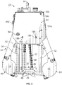
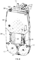
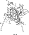
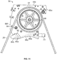
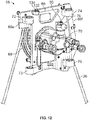
- the cutting apparatus 20 is moveable between a first or operating position (see FIGS. 1-3 ) and a second, inoperable or storage position (see FIG. 4 ).
- the cutting apparatus 20 is capable of cutting an object.
- the cutting apparatus 20 is adapted to cut a wide variety of objects.
- the cutting apparatus 20 is adapted to cut a cylindrical, hollow pipe.
- the cutting apparatus 20 may cut a variety of different diameter pipes.
- the cutting apparatus 20 may be able to cut a pipe having an outer diameter of up to about 9.6 inches.
- the cutting apparatus 20 In the storage position, the cutting apparatus 20 is very compact and can be introduced into a lot of small or tight environments that conventional cutting apparatuses or wires saws could not be introduced into and, therefore, could not be utilized. Thus, the compactness of the cutting apparatus 20 allows it to be utilized in a vast quantity of additional environments. In one example, the compactness of the cutting apparatus 20 allows the cutting apparatus 20 to pass into and through a manhole in a ground in order to access subterranean environments. Conventional cutting apparatuses and wire saws may not fit through a manhole, thereby precluding such conventional cutting apparatuses and wires saws from being used in subterranean environments.
- the cutting apparatus 20 has a compact size and shape in both the operating position and in the storage position.
- the cutting apparatus 20 has a width W of about 12 inches, a depth D of about 12 inches, and a height H of about 29 inches in the storage position.
- the cutting apparatus 20 with these dimensions will be able to easily fit into tight or small spaces such as, for example, through a manhole in the ground.
- These illustrated dimensions of the cutting apparatus 20 are only an example of a variety of possible dimensions and are not intended to limit the present disclosure. Rather, the cutting apparatus 20 is capable of having other dimensions in the storage position, but still enable the cutting apparatus 20 to be compact and fit into and through small or tight environments. All of such dimensional possibilities of the cutting apparatus 20 are intended to be within the spirit and scope of the present disclosure.
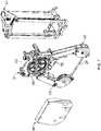
- the cutting apparatus 20 includes a feed tower assembly 22 which affixes to an object (not shown) to be cut, such as a pipe, and is stationary relative to the object, a frame assembly 24 which movable relative to the feed tower assembly 22, and a cutting member 26 removably attached to the frame assembly 24, see FIG. 7 .
- the cutting member 26 is a wire.
- the cutting member 26 may be a braided wire with diamond particles on an exterior thereof.
- the wire cutting member 26 may be a wide variety of lengths and all of such possibilities are intended to be within the spirit and scope of the present disclosure. In one example, it is a feature of the cutting apparatus 20 to include a wire cutting member of about 95 inches to about 105 inches.
- the cutting apparatus 20 of the present disclosure is capable of accommodating a wire cutting member 26 of such lengths due to its construction (described in more detail below).
- the feed tower assembly 22 is best shown in FIGS. 8 and 9 and includes a lower saddle 28, an top guide plate 30, a pair of guide shafts 32, 34 extending between and coupled to the lower saddle 28 and the top guide plate 30, a feed tower tube 36 extending between and coupled to the lower saddle 28 and the top guide plate 30, a coupling assembly 38 for coupling the feed tower assembly 22 to the object, and a frame height adjustment mechanism 40 which is configured to move the frame assembly 24 relative to the feed tower assembly 22 to cut the obj ect.
- the cutting apparatus 20 may include a variety of different coupling assemblies to couple the cutting apparatus 20 to an object.
- the coupling assembly 38 includes a handle 42, a connector 44, a wrapping member 46, and an engagement surface 48.
- the wrapping member 46 is selectively wrapped around an object, such as a pipe, and connected to the connector 44.
- the wrapping member 46 may be a wide variety of wrapping members 46 such as, for example a chain, a strap, etc.
- Rotation of the handle 42 causes the connector 44 to translate toward or away from the handle 42 depending on the direction of rotation. Translating the connector 44 toward the handle 42 tightens the wrapping member 46 around the object.
- the engagement surface 48 is arcuate or curved and is engaged by the wrapping member 46.
- the arcuate engagement surface 48 assists with equal tightening forces being applied to the object to which the cutting apparatus 20 is attached no matter the size or diameter of the object. Moreover, the arcuate engagement surface 48 ensures the wrapping member 46 extends therefrom at a proper angle that facilities evenly distributed and equal forces are applied to the object. When attaching the cutting apparatus 20 to different size objects, the wrapping member 46 will extend from different points of the arcuate engagement surface 48.
- the arcuate feature of the engagement surface accommodates the different sized objects and facilitates evenly distributed and equal forces are applied to the object.
- the saddle 28 includes a plurality of pads or saddle plates 50 adapted to engage an outer surface of the object and assist with coupling the cutting apparatus 20 to the object.
- the saddle plates 50 include engagement surfaces angled relative to each other and having a surface treatment that results in relatively high friction between the saddle plates 50 and the outer surface of the object.
- the engagement surfaces may include projections or teeth.
- the frame height adjustment mechanism 40 includes a shaft 52 and a feed handle 54 configured to rotate the shaft 52.
- the shaft 52 is coupled to and supported by the saddle 28 at its lower end and the top guide plate 30 at its upper end such that the shaft 52 can rotate relative to the saddle 28 and top guide plate 30 about a longitudinal central axis of the shaft 52, but is prohibited from moving vertically or axially along the central axis.
- the shaft 52 has external threads defined in an exterior thereof.
- the handle 54 is fixedly coupled to a top end of the shaft 52 and is manipulatable by an operator to rotate the shaft 52 in two directions.
- the frame assembly 24 includes a frame base plate assembly 56, a wire tensioning assembly 58 mounted on the frame base plate assembly 56 and vertically movable relative to the frame base plate assembly 56, a right arm assembly 60 pivotally mounted on the wire tensioning assembly 58, a left arm assembly 62 pivotally mounted on the frame base plate assembly 56, a cover 64 hingedly mounted on the frame base plate assembly 56, and the cutting member 26.
- the wire tensioning assembly 58 is adjustable to adjust a quantity of tension applied to the cutting member 26 and may be adjusted to allow removal and replacement of the cutting member 26.
- the frame base plate assembly 56 includes a frame base plate 66 having a front surface 66a, a rear surface 66b, a top surface 66c, a bottom surface 66d and right and left side surfaces 66e, 66f, a drive wheel 68 rotatably mounted on the front surface 66a thereof, and a drive mechanism 70 mounted on the rear surface 66b thereof and attached to the drive wheel 68 to operate the drive wheel 68.
- the frame base plate 66 has trunnions 72, 73, 74, 76 and a frame block 78 extending outwardly from the rear surface 66b thereof.
- Each trunnion 72, 73, 74, 76 has a passageway provided from between a top surface and a bottom surface thereon, and a bushing is mounted in each passageway.
- a drive shaft of the drive mechanism 70 extends through an aperture provided through the frame base plate 66.
- the drive wheel 68 is proximate to the front surface 66a of the frame base plate 66 and is coupled to the drive mechanism 70 on the rear surface 66b of the frame base plate 66 via the drive shaft.
- Trunnions 74, 76 are provided on one of side of the drive mechanism 70 and are vertically aligned with each other.
- Trunnions 72, 73 are provided on the other side of the drive mechanism 70, are vertically aligned with each other, trunnion 72 is horizontally aligned with trunnion 74, and trunnion 73 is horizontally aligned with trunnion 76.
- the frame block 78 has a threaded passageway 80 therethrough which extends from an upper surface of the frame block 78 to a lower surface of the frame block 78.
- the frame base plate 66 further has a left arm retaining block 82 and an arm mounting pin 84 extending outwardly from the front surface 66a.
- the left arm retaining block 82 is proximate to the bottom surface 66d and proximate to the corner between the bottom surface 66d and the left side surface 66f.
- the left arm retaining block 82 has first and second spaced apart notches 86a, 86b provided in a lower surface thereof.
- the drive mechanism 70 is a hydraulic drive system.
- the drive mechanism 70 may be a motor, a pneumatic drive mechanism, an electric drive mechanism, etc.
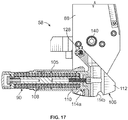
- the wire tensioning assembly 58 includes a wire tensioning base plate 88 having a front surface 88a and a rear surface 88b, a right arm adjustment mechanism 90 mounted on the front surface 88a thereof, a tension indicator mechanism 92 mounted on the rear surface 88b thereof, and a wire tensioning height adjustment mechanism 94 mounted on the rear surface 88b thereof.
- the wire tensioning height adjustment mechanism 94 works in conjunction with a wheel slide block 132 extending from the frame base plate 66.
- the wheel slide block 132 has a passageway therethrough which extends from an upper surface of the wheel slide block 132 to a lower surface of the wheel slide block 132 in which bushings 134 are seated.
- a trunnion 96 extends outwardly from the rear surface 88b of the wire tensioning base plate 88.
- the trunnion 96 has a passageway 98 extending between a top surface and a bottom surface thereof, and a bushing is mounted therein.
- a bore 100 extends downwardly from the top surface of the trunnion 96 and is spaced from the passageway 98, and a threaded feed nut is mounted therein.
- the wire tensioning height adjustment mechanism 94 includes a threaded rod 102 having a knob 104 at an upper end of the rod. A lower end of the rod 102 is threadedly engaged with the feed nut in the bore 100.
- the rod 102 is rotatable relative to the trunnion 96, and the trunnion 96, and thus the wire tensioning base plate 88 translates along the rod 102 upon rotation of the rod 102.
- the right arm adjustment mechanism 90 includes a housing 105 having a piston 106 extending outwardly therefrom and a spring 108 within the housing 105 to bias the piston 106.
- the piston 106 includes a shaft 110 having an enlarged piston head 112 at an end thereof.
- a notch 114a is provided in a lower surface of the housing 105 proximate to the end of the housing 105 from which the piston 106 extends.
- a notch 114b is provided in a lower surface of the piston head 112.
- the tension indicator mechanism 92 includes a housing 116 which extends outwardly from the rear surface 88b of the wire tensioning base plate 88 at a position spaced below the trunnion 96, a passageway 118 through the housing 116 which extends from a front side 116a of the housing 116 to a rear side 116b thereof, a movable indicator arm 120 positioned within the passageway 118 and pivotally connected to the housing 116 by an arm mounting pin 122, and a rod 124 pivotally attached to the indicator arm 120 by an arm mounting pin 126.
- the indicator arm 120 is L-shaped.
- the rod 124 is fixedly attached to an upper end of the piston head 112 and extends through an elongated horizontal slot 128 through the wire tensioning base plate 88.
- the housing 116 has indicia 130 thereon which correspond to a "SET” position, a "CUT 1" position and a "CUT 2" position.
- An end 120a of the movable indicator arm 120 is visible from above the housing 116 so that an operator can see when the end 120a aligns with one of the "SET” position, the "CUT 1" position and the "CUT 2" position.
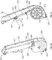
- the right arm assembly 60 includes a rear plate 136 and a front plate 138 in a parallel arrangement.
- a plurality of spacers 141 are disposed between the parallel plates 136, 138 to separate the rear plate 136 from the front plate 138 by a predetermined distance.
- An inner side opening is provided between the plates 136, 138 on an inner side thereof; a bottom opening is provided between the plates 136, 138 on a bottom side thereof; and an outer side opening is provided between the plates 136, 138 on an outer side thereof, and a top opening is provided between the plates 136, 138 on a top side thereof.
- An arm mounting pin 140 extends outwardly from the front surface 88a of the wire tensioning base plate 88 and extends through the plates 136, 138 proximate to the top ends thereof to attach the right arm assembly 60 to the frame base plate 66 of the wire tensioning assembly 58 vertically upwardly of the piston head 112.
- An arm wheel 142 is rotationally mounted between the plates 136, 138 proximate to the bottom ends thereof by an axle 144 mounted between the plates 136, 138.
- the arm mounting pin 140 may be integrally formed with the wire tensioning base plate 88 such that a one-piece member is provided.
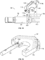
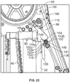
- a spring-biased latch 146 is pivotally attached to the plates 136, 138 by an arm mounting pin 148 extending between the plates 136, 138.
- the spring-biased latch 146 includes a latch arm 150 and a spring 152.
- the latch arm 150 has an elongated handle section 150a, a pivot mount section 150b extending outwardly from the handle section 150a proximate to an upper end thereof, and a finger section 150c which protrudes upwardly from the upper end of the handle section 150a.
- the finger section 150c has a curved end surface 154.
- the spring 152 has a first end section 152a which is engaged with the pivot mount section 150b, a coiled section 152b extending from the first end section 152a which is wrapped around the pin 148, and a second end section 152c extending from the coiled section 152b and which is engaged with one of the spacers 141.
- the spring 152 normally biases the latch arm 150 into a first position such that a lower end 156 of the handle section 150a of the latch arm 150 is pivoted away from the plates 136, 138.
- the finger section 150c can seat within the notch 114a provided in the piston housing 105 or can seat within the notch 114b provided in the piston head 112.
- the finger section 150c is seated within the notch 114a provided in the piston housing 105, the right arm assembly 60 is in the storage position.
- the finger section 150c is seated within the notch 114b provided in the piston head 112, the right arm assembly 60 is in the operating position.
- the notches 114a, 114b are slightly larger than the finger section 150c such that the finger section 150c can be released from the notches 114a, 114b when an operator pivots the latch arm 150 around its arm mounting pin 148.
- the notch 114b is sized to allow the finger section 150c to pivot within the notch 114b, but to maintain engagement of the finger section 150c and the piston head 112.
- the left arm assembly 62 includes a rear plate 158 and a front plate 160 in a parallel arrangement.
- a plurality of spacers 162 are disposed between the parallel plates 158, 160 to separate the rear plate 158 from the front plate 160 by a predetermined distance.
- An inner side opening is provided between the plates 158, 160 on an inner side thereof; a bottom opening is provided between the plates 158, 160 on a bottom side thereof; and an outer side opening is provided between the plates 158, 160 on an outer side thereof, and a top opening is provided between the plates 158, 160 on a top side thereof.
- the arm mounting pin 84 extends outwardly from the frame base plate 66 and extends through the plates 158, 160 proximate to the top ends thereof to attach the left arm assembly 62 to the frame base plate 66 of the frame base plate assembly 56 vertically upwardly of the left arm retaining block 82.
- An arm wheel 164 is rotationally mounted between the plates 158, 160 proximate to the bottom ends thereof by an axle 166 mounted between the plates 158, 160.
- the arm mounting pin 84 may be integrally formed with the frame base plate 66 such that a one-piece member is provided.
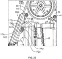
- a spring-biased latch 168 is pivotally attached to the plates 158, 160 by an arm mounting pin 170 extending between the plates 158, 160.
- the spring-biased latch 168 includes a latch arm 172 and a spring 174.
- the latch arm 172 has an elongated handle section 172a, a pivot mount section 172b extending outwardly from the handle section 172a proximate to an upper end thereof, and a finger section 172c which protrudes upwardly from the upper end of the handle section 172a.
- the finger section 172c has a curved end surface 176.
- the spring 174 has a first end section 174a which is engaged with the pivot mount section 172b, a coiled section 174b extending from the first end section 174a which is wrapped around the pin 170, and a second end section 174c extending from the coiled section 174b and which is engaged with one of the spacers 162.
- the spring 174 normally biases the latch arm 172 into a first position such that a lower end 178 of the handle section 172a of the latch arm 172 is pivoted away from the plates 158, 160.
- the finger section 172c can seat within the notch 86a or in the notch 86b provided in the left arm retaining block 82.
- the finger section 172c is seated within the notch 86a, the left arm assembly 62 is in the storage position.
- the finger section 172c is seated within the notch 86b, the left arm assembly 62 is in the operating position.
- the notches 86a, 86b are slightly larger than the finger section 172c such that the finger section 172c can be released from the notches 86a, 86b when an operator pivots the latch arm 172 around its arm mounting pin 170.
- each arm wheel 142, 164 includes a central hub 180 and an outer body member 182.
- Each arm wheel 142, 164 defines a pair of spaced-apart flanges and a recess between the flanges for receiving the cutting member 26 therein.
- the arm wheel 142, 164 are formed of plastic with a cast urethane wear surface to provide the arm wheel 142, 164 with sufficient strength and durability to withstand the stresses realized during operation of the cutting apparatus 20.
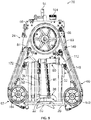
- the cutting member 26 forms a loop around the drive wheel 168 and the arm wheels 142, 164.
- the cutting member 26 is attached to the drive wheel 68 and partially encircles the drive wheel 68, is attached to the arm wheel 142 of the right arm assembly 60 and partially encircles the arm wheel 142, and is attached to the arm wheel 164 of the left arm assembly 62 and partially encircles the arm wheel 164.
- the guide shaft 34 of the feed tower assembly 22 extends through the trunnions 74, 76 extending from the frame base plate 66 of the frame base plate assembly 56.
- the guide shaft 32 of the feed tower assembly 22 extends through the trunnions 72, 73 on the frame base plate 66 of the frame base plate assembly 56 and through the passageway 98 of the trunnion 96 extending from the wire tensioning base plate 88 of the wire tensioning assembly 58.
- the shaft 52 of the feed tower assembly 22 extends through and is threadedly engaged with the passageway 80 of the frame block 78 extending from the frame base plate 66 of the frame base plate assembly 56.
- the rod 102 of the wire tensioning height adjustment mechanism 94 of the wire tensioning assembly 58 extends through the top guide plate 30 of the feed tower assembly 22 and the knob 104 is above the top guide plate 30.
- the rod 102 of the wire tensioning assembly 58 further extends through the bushings 134 in the passageway of the wheel slide block 132 of the base frame assembly 24 and is captively engaged with the bushings 134. This couples the feed tower assembly 22, the frame base plate assembly 56 and the wire tensioning assembly 58 together.
- the arm assemblies 60, 62 are moved to the operating position by pivoting the latches 150, 172 to engage the finger sections 150c, 172c into the notches 114b, 86b, and the feed tower assembly 22 is mounted to the object using the coupling assembly 38.
- the wrapping member 46 is uncoupled from the connector 44, the cutting apparatus 20 is positioned on top of the object such that the saddle plates 50 engage the object, the wrapping member 46 is wrapped around the object, the wrapping member 46 is coupled again to the connector 44, and the handle 42 is rotated in a direction that causes the connector 44 to translate toward the handle 42, thereby tightening the wrapping member 46 around the object.
- the handle 42 is rotated until a desired amount of tension and forces are applied to the object to ensure a secure coupling of the cutting apparatus 20 to the pipe.
- the wrapping member 46 will engage and extend from the arcuate engagement surface 48 at a location dependent upon the size or diameter of the pipe.
- the cutting member 26 will be in engagement with an upper surface of the object to be cut. Thereafter, the knob 104 is rotated to rotate the rod 102 of the wire tensioning height adjustment mechanism 94 relative to the top guide plate 30 of the feed tower assembly 22 and relative to the wheel slide block 132. This causes the wire tensioning base plate 88 to move relative to the frame base plate 66, thereby causing the right arm assembly 60 to move upwardly or downwardly depending upon which direction the knob 104 is rotated. As a result, the right arm assembly 60 moves relative to the drive wheel 68, relative to the left arm assembly 62, and relative to the object. The trunnion 98 slides along the guide shaft 32 during this movement. When the right arm assembly 60 is moved downwardly, the cutting member 26 presses against the object.
- the right arm assembly 60 pivots around its arm mounting pin 140 and rotates inwardly against the action of the spring-biased piston 106 (to the extent that the spring force of the spring-biased piston 106 allows for such movement).
- the spring 108 within the piston housing 105 compresses, and the rod 124 translates along the slot 128, which in turn causes the indicator arm 120 to pivot within the passageway 118 of the housing 116.
- Rotation of the knob 104 and rod 102 is continued until the indicator arm 120 aligns with the "SET" position. Movement of the right arm assembly 60 upwardly decreases the tension on the cutting member 26. Movement of the right arm assembly 60 downwardly increases the tension on the cutting member 26.
- the cutting member 26 When in the "SET" position, the cutting member 26 "bends" around the object. By having the bend in the cutting member 26, more surface area of the cutting member 26 is engaging the object rather than just a small surface area if the cutting member 26 is too taut and extends straight or substantially straight across between the arm wheels 142, 164. Greater surface area engagement between the cutting member 26 and the object facilitates more effective cutting of the object.
- the object is ready to be cut.
- the operator turns the feed handle 54 of the frame height adjustment mechanism 40 to move the frame base plate assembly 56, the wire tensioning assembly 58, both arm assemblies 60, 62 and the cutting member 26 downwardly toward the object and relative to the feed tower assembly 22.
- the frame base plate assembly 56, the wire tensioning assembly 58, both arm assemblies 60, 62 and the cutting member 26 are moved downwardly, the cutting member 26 presses against the object.
- the right arm assembly 60 pivots around its arm mounting pin 140 and rotates inwardly.
- the piston head 112 moves inwardly from the piston housing 105 under the force from the spring 108.
- the rod 124 translates along the slot 128, which in turn causes the indicator arm 120 to pivot within the passageway 118 of the housing 116 to the desired "CUT 1" position or “CUT 2" position.
- the operator maintains a rotation rate on the feed handle 54 which keeps the indicator arm 120 at the desired "CUT 1" position or “CUT 2" position.
- the cutting member 26 will then cut through the object. This represents the balance and dynamic tension between the "payout” or slack in the cutting member 26 and the pressure exerted on the cutting member 26 during cutting. Dynamic movement adjusts the tension in the cutting member 26 during operation. For a given amount of slack, a certain wire pressure is operator-maintained for optimal cutting.
- the cutting member 26 When the cutting apparatus 20 is not engaged with the object, the cutting member 26 can be released from the drive wheel 68 and the arm wheels 142, 164 for replacement. It may be desirable to remove and replace a cutting member 26 for example, if the cutting member 26 is worn out, damaged, or a different type of cutting member 26 is desired based on the type of object to be cut.
- the cutting member 26 may be removed from the cutting apparatus 20 when the cutting apparatus 20 is in either the storage position or the operating position (i.e., with the two arm assemblies 60, 62 inward or outward).
- the wire tensioning assembly 58 is used to raise the right arm wheel 142 upwardly toward the drive wheel 68.
- the wire tensioning assembly 58 is used to lower the arm wheel 142 away from the drive wheel 68 in a second direction opposite the first direction, thereby increasing or applying tension to the cutting member 26.
- a guard 186 may extend outwardly from the front surface 88a of the wire tensioning base plate 66 proximate to the upper end of the right arm assembly 60.
- the cover 64 can be selectively opened to provide access to the drive wheel 68, and can be closed to prevent access to and to protect the drive wheel 68.
- the cover 64 is coupled to the frame base plate 66 by a plurality of pins 188, a hinge 190 and a latch 192.
- the cover 64 has a front wall 194a having front and rear surfaces, a top wall 194b depending from a top end of the front wall 194, and side walls 194c, 194c depending from the opposite sides of the front wall 194a.
- a plurality of openings 196 are provided through the cover 64.
- each pin 188 has an elongated shaft 198 which extends outwardly from the front surface 66a of the frame base plate 66, a flange 200 extending radially outwardly from the shaft 198, and an enlarged head 202 at the end of the shaft 198 and which is spaced from the flange 200.
- a recess 203 is provided between the head 202 and the flange 200.
- Each opening 196 is larger than the head 202 of the respective pin 188, but smaller than the flange 200.
- the hinge 190 has cylindrical knuckles 204 coupled to the frame base plate 66, and cylindrical leaves 206 coupled to the side wall 194d of the cover 64.
- the leaves 206 are connected together by a bar 208.
- Pins 210 extend through the respective knuckles/leaves 204/206.
- the latch 192 has a first part on the top wall 192b of the cover 64 and a second mating part on the top surface of the frame base plate 66. When the parts of the latch 192 are engaged with each other, the cover 64 cannot be opened.
- the top wall 194b of the cover 64 overlaps the top surface of the frame base plate 66
- the side walls 194c, 194d of the cover 64 overlap the sides of the frame base plate 66
- the bottom edge of the front wall 192a aligns with, or is below, the bottom edge of the frame base plate 66.
- the pins 188 are positioned at the top of the openings 196, with the heads 202 of the pins 188 extending through respective openings 196 and the front wall 196a seats within the recess 203 of each pin 188.
- Each leaf 206 is proximate to the respective knuckle 204.
- the front wall 194a of the cover 64 covers the drive wheel 68, the frame base plate assembly 56, the wire tensioning assembly 58, and an upper portion of each arm assembly 60, 62.
- the side walls 194c, 194d cover the sides of the drive wheel 68.
- the parts of the latch 192 are disengaged. Thereafter, the operator lifts the cover 64 upwardly.
- the leaves 206 travel upwardly along the pins 210.
- the cover 64 is rotated around the pins 210 to move the cover 64 to the open position.
- the cover 64 is rotated around the pins 210 until the rear surface of the front wall 194a of the cover 64 engages with the heads 202 of the pins 188.
- the heads 202 of the pins 188 are conical, so the cover 64 will slide along the heads 202 to move upwardly relative to the pins 188 and the frame base plate 66.
- the cover 64 will drop into the recesses 203. Thereafter, the latch 192 is reengaged.
- the cutting apparatus 20 may be set-up, operated, and configured into its storage position all without the use of tools, which eliminates the need to carry or keep track of tools.
- the orientation and configuration of all of the wheels 68, 142, 164 of the cutting apparatus 20 enable the cutting apparatus 20 to include a cutting member 26 of a relatively long length.
- the cutting member 26 can have a length of about 105 inches.
- the cutting member 26 can have a length between about 95 inches and about 120 inches.
- the quantity that the cutting member 26 wraps around each of the wheels 68, 142, 164 may be specifically designed to inhibit slippage between the cutting member 26 and the wheels 68, 142, 164 during operation and provide sufficient support to the cutting member 26.
- all of the wheels 68, 142, 164 are aligned and centered in a common plane, which inhibits drifting and pitching of the wheels 68, 142, 164 during operation of the cutting apparatus 20.
- the cutting apparatus 20 With the cutting apparatus 20 in its storage position, the cutting apparatus 20 is compact and can be transported, such as by carrying, to a variety of environments that conventional cutting apparatuses could not previously be transported to. For example, the cutting apparatus 20 may easily pass through a manhole opening in the ground to perform work on subterranean pipes. Conventional cutting apparatuses may be too large to pass through a manhole.
- the cutting apparatus 20 Once the cutting apparatus 20 is at or near a desired cutting location, the cutting apparatus 20 may either be initially coupled to an object or initially moved from its storage position to its operating position.
- the object has been described as a pipe. However, the cutting apparatus 20 is adapted to cut a wide variety of objects and the description herein pertaining to a pipe is not intended to be limiting to the present disclosure.
- the engagement of the latches 150, 172 with the piston head 112 and the left arm retaining block 82 when in the operating position provide structural support for the arm assemblies 60, 62 when under load, and also provides structural rigidity for the arm assemblies 60, 62 when under load.
- the arm assemblies 60, 62 are loaded between the upper arm mounting pins 140, 84 and the arm wheels 142, 164. The entire load is supported by the arm assemblies 60, 62.
- the latches 150, 172 are engaged with the piston head 112 and the left arm retaining block 82 at about the mid-point of each arm assembly 60, 62, and preferably may be positioned slightly toward the upper arm mounting pins 140, 84. This stabilizes the arm wheels 142, 164. Because the arm assemblies 60, 62 are not supported in a cantilevered manner, all forces acting due to tension in the cutting member 26 act in single plane, that is, in the plane of the cutting member 26, the drive wheel 68 and the arm wheels 142, 164. Lateral deflection of the arm assemblies 60, 62 is prevented due to relatively tight frictional fit between the latches 150, 172 and the piston head 112 and the left arm retaining block 82.
- the number of components disposed on the front surface 66a of the frame base plate 66 and the front surface 88a of the wire tensioning base plate 88 are minimized because it is this area that may be subject to the accumulation of debris during the cutting operation. No sensors, springs, or sensitive components are located in this area specifically to isolate such components from any such debris.
- the cover 64 and the frame base plate 66 essentially isolates the sensitive components disposed on the rear surface 66b of frame base plate 66 from the debris area associated with the front surface 66a of the frame base plate 66, because minimal pathways are provided therebetween. Because the arm wheels 142, 164 create a fan-like action when rotating to sweep debris away from the wheel center. Thus, the components on the rear surface 66b of the frame base plate 66 remain isolated and protected from debris.
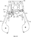
- each arm assembly 60, 62 includes a lower latchable door 250 which closes the bottom opening between the plates 136, 138, 158, 160, and an upper latchable door 252 which closes the outer side opening between the plates 136, 138, 158, 160.
- the doors 250 are shaped to conform to the shape of the bottom opening between the plates 136, 138, 158, 160 and are pivotally attached to the plates 136, 138, 158, 160 by arm mounting pin 254.
- the doors 252 are shaped to conform to the outer side opening between the plates 136, 138, 158, 160 and are hingedly attached to the plate 136, 158 by a hinge 256.
- a latch part 258 is attached to the other plate 138, 160 and mates with a latch part 260 on the upper door 252.
- an upper end of the lower door 250 engages with the lower end of the upper door 252 such that the upper end of the lower door 250 is inwardly of the lower end of the upper door 252.
- the latch parts 258, 260 are engaged to maintain both doors 250, 252 in a closed position.
- the latch parts 258, 260 are disengaged and the upper door 252 rotates around its hinge 256, thereby exposing the outer opening.
- the lower door 250 is free to rotate around its arm mounting pin 254 by gravity, thereby exposing the bottom opening.
- the interior portion of the arm assemblies 60, 62, including the arm wheels 142, 164 may be easily cleaned so as to remove debris that may accumulate during the cutting process.
- a housing 262 around the arm mounting pin 254 of the lower door 250 may be hardened such that if the cutting member 26 is severed, the arm mounting pin 254 will be resistant to damage.
- latchable doors 250, 252 in the open position, changing the cutting member 26 is fast and easy, and no tools are required. Note that the latching doors 250, 252 merely provide access to the internal partially enclosed space between the plates 136, 138, 158, 160 and are not needed to provide structural support or integrity for the arm assemblies 60, 62.
- the cutting apparatus 20 includes a liquid dispensing assembly 264 adapted to dispense pressurized liquid to assist with cooling portions of the cutting apparatus 20 during operation.
- a large quantity of heat can be realized when using the cutting apparatus 20 to cut an object. Excessive quantities of heat can undesirably damage the cutting member 26 and/or components of the cutting apparatus 20.
- the liquid dispensing assembly 264 assists with inhibiting excessive heat during operation.
- the liquid dispensing assembly 264 also decreases the amount of debris that moves upward into the cutting apparatus 20 during operation of the cutting apparatus 20.
- the liquid dispensed from the liquid dispensing assembly 264 engages debris, captures the debris and falls or runs downward, thereby bringing the debris with it as it falls. Excessive debris buildup in the cutting apparatus 20 may negatively affect operation of the cutting device and/or damage the cutting apparatus 20.
- the liquid is water.
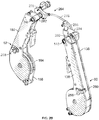
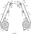
- the liquid dispensing assembly 264 includes right and left dispensers or sprayers 266, 268 and right and left conduits 270, 272 for communicating pressurized liquid to the dispensers 266, 268, see FIG. 30 .
- Dispenser 266 is coupled to an interior surface of the plate 136 of the right arm assembly 60 and conduit 270 is connected to the dispenser 266;
- dispenser 268 is coupled to an interior surface of the plate 158 of the left arm assembly 62 and conduit 272 is connected to the dispenser 268.
- the conduits 270, 272 communicate liquid to the respective dispenser 266, 268.
- Each conduit 270, 272 may be rigid.
- the liquid dispensing assembly 264 further includes a right liquid passageway block 274, a left liquid passageway block 276, a flexible conduit 278 extending between the right and left liquid passageway blocks 274, 276, a right mounting pin housing 280, and a left mounting pin housing 282.
- the right liquid passageway block 274 extends from the rear surface 88b of the wire tensioning base plate 88.
- the right liquid passageway block 274 may be integrally formed with the wire tensioning base plate 88 such that a one-piece member is provided.
- the right liquid passageway block 274 has a passageway 284 therethrough which extends from a rear thereof to a front thereof.
- the passageway 284 has a rear end 284a at the rear of the right liquid passageway block 274 and which is connected to the flexible conduit 178, and a front end 284b at the front of the right liquid passageway block 274 which is communication with an aperture (not shown) through the wire tensioning base plate 88.
- the right liquid passageway block 274 may take the form of a trunnion and have the support rod 32 extending therethrough and may further have a support rod 286 extending therethrough; the support rod 286 being affixed to the frame base plate 66.
- the left liquid passageway block 276 extends from the rear surface 66b of the frame base plate 66.
- the left liquid passageway block 276 may be integrally formed with the frame base plate 66 such that a one-piece member is provided.
- the left liquid passageway block 276 has a passageway 288 therethrough having a first branch 290 which extends from a rear of the left liquid passageway block 276 to a front of the left liquid passageway block 276, and a second branch 292 which extends from the first branch 290 to the rear of the left liquid passageway block 276.
- the first branch 290 has a rear end 290a at the rear of the left liquid passageway block 276 and which is connected to a source (not shown) of pressurized liquid, and a front end 290b at the front of the left liquid passageway block 276 which is in fluid communication with an aperture (not shown) through the frame base plate 66.
- the second branch 292 has a rear end 292a at the rear of the left liquid passageway block 276 and which is connected to the flexible conduit 278, and a front end 292b which is in fluid communication with the first branch 290.
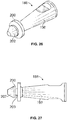
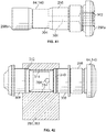
- each mounting pin housing 280, 282 is identically formed. As shown in FIGS. 36-38 , each mounting pin housing 280, 282 has a passageway 294 which extends axially from a rear end of the mounting pin housing 280, 282 to a front end of the mounting pin housing 280, 282, and a passageway 296 which intersects and extends radially outwardly from the passageway 294 to an exterior of the mounting pin housing 280, 282.
- the conduit 270 is attached to the end 296a of the passageway 296.
- the conduit 272 is attached to the end 296a of the passageway 296.
- each arm mounting pin 84, 140 forms part of the liquid dispensing assembly 264.
- Each arm mounting pin 84, 140 is identically formed.
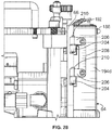
- each arm mounting pin 84, 140 has a body 298 having a rear end 298a, a front end 298b and an exterior surface 298c, and a passageway therethrough which is formed from a bore 300 which extends axially from an opening 302 at the rear end 298a toward the front end 298b and a through hole 304 which extends diametrically across the arm mounting pin 84, 140 and intersects the bore 300 and terminates at the exterior surface 298c of the arm mounting pin 84, 140.
- the bore 300 is blind such that the bore 300 does not extend to the front end 298b of the arm mounting pin 84, 140.
- each arm mounting pin 84, 140 has a pair of spaced apart bushings 306, 308 mounted thereon which encircle the body 298.
- the plates 136, 138 are attached to the respective bushings 306, 308 which allow the plates 136, 138 to rotate relative to the right arm mounting pin 140.
- the right arm mounting pin 140 extends through plates 136, 138 and extends through the passageway 294 of the right mounting pin housing 280 such that the right mounting pin housing 280 is between the plates 136, 138.
- the plates 158, 160 are attached to the respective bushings 306, 308 which allow the plates 158, 160 to rotate relative to the left arm mounting pin 84.
- the left arm mounting pin 84 extends through plates 158, 160 and extends through the passageway 294 of the left mounting pin housing 282 such that the left mounting pin housing 282 is between the plates 158, 160.
- O-rings 310, 312 seal the mounting pin housings 280, 282 to the arm mounting pins 84, 140 such that a cavity 314 is provided between the right mounting pin housing 280 and the right arm mounting pin 140 and is provided between the left mounting pin housing 282 and the left arm mounting pin 84.
- the cavity 314 is in fluid communication with the bore 300 and the through hole 304 the passageways 294, 296 in the right mounting pin housing 280 and with the through hole in the arm mounting pin 140.
- the O-rings 310, 312 are eliminated and the mounting pin housing 280, 282 and respective arm mounting pin 84, 140 are integrally formed with each other such that a one-piece member is provided.
- liquid flows from the source, through the first branch 290 of the left liquid passageway block 276 and flows through the second branch 292 thereof.
- the liquid in the first branch 290 flows through the opening 302 in the left arm mounting pin 84, through the bore 300 of the left arm mounting pin 84 and then through the through hole 304 of the left arm mounting pin 84.
- the liquid then flows into the cavity 314 between the left arm mounting pin 84 and the left mounting pin housing 282.
- the liquid flows through the passageway 296 of the left mounting pin housing 282 and then into the left conduit 272 to the left dispenser 268 in the left arm assembly 62.
- the liquid flows out of the left dispenser 268 and onto the left arm wheel 164.
- the liquid also flows from the second branch 292, through the flexible conduit 178 and into and through the passageway 284 in the right liquid passageway block 274.
- the liquid then flows through the opening 302 in the right arm mounting pin 140, through the bore 300 of the right arm mounting pin 140 and then through the through hole 304 of the right arm mounting pin 140.
- the liquid then flows into the cavity 314 between the right arm mounting pin 140 and the right mounting pin housing 280.
- the liquid flows through the passageway 296 of the right mounting pin housing 280 and then into the right conduit 270 to the right dispenser 266 in the right arm assembly 62.
- the liquid flows out of the right dispenser 266 and onto the right arm wheel 142.
- the flexible conduit 278 allows the movement between the operating position and the storage position of the arm assemblies 60, 62 as described. If the conduit 278 was completely rigid, the conduit 278 may break or fracture due to the movement of the arm members 120.
- the two dispensers 266, 268 dispense a liquid onto the cutting member 26 and the adjacent arm wheel 142, 164 at or near the location where the cutting member 26 engages the wheel 142, 164.
- Each dispenser 266, 268 includes a liquid exhaust aperture and a deflector for deflecting the exhausted liquid at a desired angle. The deflector is angled to deflect the liquid at or near the point where the cutting member 26 engages the wheel 142, 164.
- the pressurized liquid spray cools the cutting member 26 and removes debris during operation.
- Most of the components of the cutting apparatus 20 are located the rear surface 66b of the frame base plate 66 so as not to impede cleaning of debris or trap any debris.
- the operator need only open the cover 64 and the latchable doors 250, 252, and spray the area with a source of liquid from an external hose.
- any orientation or directional terms herein such as, for example, “top”, “bottom”, “front”, “rear”, “back”, “left”, “right”, “side”, etc., is not intended to imply only a single orientation of the item with which it is associated or to limit the present disclosure in any manner.
- the use of such orientation or directional terms is intended to assist with the understanding of principles disclosed herein and to correspond to the exemplary orientation illustrated in the drawings.
- the cutting apparatus may be utilized in any orientation and use of such terms is intended to correspond to the exemplary orientation of the cutting apparatus illustrated in the drawings.
- the use of these terms in association with the cutting apparatus is not intended to limit the cutting apparatus to a single orientation or to limit the cutting apparatus in any manner.
Landscapes
- Engineering & Computer Science (AREA)
- Mechanical Engineering (AREA)
- Processing Of Stones Or Stones Resemblance Materials (AREA)
- Sawing (AREA)
- Finish Polishing, Edge Sharpening, And Grinding By Specific Grinding Devices (AREA)
Claims (15)
- Appareil de coupe (20) comportant :un ensemble de tour d'alimentation (22) configuré pour être fixé à un objet à couper ;un ensemble de plaque de base de cadre (56) comportant une plaque de base de cadre (66) et une roue motrice entraînée (68) montée sur la plaque de base de cadre (66) ;un mécanisme d'ajustement de plaque de base de cadre (40) couplé à la plaque de base de cadre (66) et à l'ensemble de tour d'alimentation (22) et configuré pour déplacer l'ensemble de plaque de base de cadre (56) vers le haut et vers le bas par rapport à l'ensemble de tour d'alimentation (22) ;un ensemble de tension de fil (58) comportant une plaque de base de tension de fil (88) et un mécanisme de réglage de hauteur de tension de fil (94), le mécanisme de réglage de hauteur de tension de fil (94) étant couplé à la plaque de base de cadre (66) et à la plaque de base de tension de fil (88) et configuré pour déplacer la plaque de base de tension de fil (88) vers le haut et vers le bas par rapport à la paroi de plaque de base de cadre ;un ensemble de bras droit (60) monté de manière pivotante sur la plaque de base de tension de fil (88) de sorte que l'ensemble de bras droit (60) peut être positionné dans une position de fonctionnement ou une position de stockage, l'ensemble de bras droit (60) comportant une plaque de bras droit ayant une roue de bras (142) montée de manière rotative sur celle-ci ;un mécanisme de réglage de bras droit (90) couplé à la plaque de base de tension de fil (88) et à la plaque de bras droit et configuré pour faire pivoter l'ensemble de bras droit (60) par rapport à la plaque de base de tension de fil (88) ;un ensemble de bras gauche (62) monté sur la plaque de base de cadre (66), l'ensemble de bras gauche (62) comportant une plaque de bras gauche ayant une roue de bras (164) montée de manière rotative sur celle-ci ; etun élément de coupe (26) partiellement enroulé autour des roues de bras (142, 164) et de la roue motrice (68).
- Appareil de coupe (20) selon la revendication 1, dans lequel l'ensemble de bras gauche (62) est monté de manière pivotante sur la plaque de base de cadre (66) de sorte que l'ensemble de bras gauche (62) peut être positionné dans une position de fonctionnement ou une position de rangement.
- Appareil de coupe (20) selon la revendication 2, comportant en outre un verrou fixé à l'ensemble de bras gauche (62) et configuré pour être fixé à la plaque de base de cadre (66) .
- Appareil de coupe (20) selon la revendication 1, comportant en outre un verrou fixé à l'ensemble de bras droit (60) et configuré pour être fixé à la plaque de base de tension de fil (88).
- Appareil de coupe (20) selon la revendication 1, dans lequel le mécanisme d'ajustement de hauteur de tension de fil (94) comporte un bloc (132) s'étendant à partir de la plaque de base de cadre (66), et une tige (102) engagée avec le bloc et engagée avec la plaque de base de tension de fil (88), dans lequel une rotation de la tige (102) provoque un mouvement vertical de la plaque de base de tension de fil (88) et de l'ensemble de bras droit (60) par rapport à l'ensemble de plaque de base de cadre (56) et à l'ensemble de tour d'alimentation (22).
- Appareil de coupe (20) selon la revendication 5, dans lequel la plaque de base de cadre (66) a une surface avant et une surface arrière, la roue motrice (68) étant montée sur la surface avant de la plaque de base de cadre (66) et le bloc (132) s'étendant à partir de la surface arrière de la plaque de base de cadre (66).
- Appareil de coupe (20) selon la revendication 1, dans lequel le mécanisme de réglage de bras droit (90) comporte un piston à ressort monté sur la plaque de base de tension de fil (88) et engagé avec l'ensemble de bras droit (60).
- Appareil de coupe (20) selon la revendication 7, comportant en outre un indicateur de tension couplé au piston utilisé pour indiquer la quantité de tension sur l'élément de coupe (26).
- Appareil de coupe (20) selon la revendication 8, dans lequel l'indicateur de tension comporte un logement ayant un bras indicateur monté de manière pivotante dans celui-ci, et une tige couplée au bras indicateur et au piston.
- Appareil de coupe (20) selon la revendication 7, dans lequel la plaque de base de tension de fil (88) a une surface avant et une surface arrière, la roue motrice (68) étant montée sur la surface avant de la plaque de base de cadre (66) et le mécanisme de réglage de bras droit (90) s'étendant à partir de la surface avant de la plaque de base de tension de fil (88).
- Appareil de coupe (20) selon la revendication 1,dans lequel l'ensemble de tour d'alimentation (22) comporte un socle, une plaque de guidage supérieure, une pluralité d'arbres de guidage s'étendant entre le socle et la plaque de guidage supérieure ;dans lequel le mécanisme de réglage de plaque de base de cadre (40) comporte une tige fixée à la plaque de guidage supérieure et rotative par rapport à celle-ci, et fixée à la plaque de base de cadre (66),dans lequel la rotation de la tige par rapport à la plaque de guidage supérieure provoque la translation de la plaque de base de cadre (66) par rapport à l'ensemble de tour d'alimentation (22).
- Appareil de coupe (20) selon la revendication 1, comportant en outre un couvercle monté de manière articulée sur la paroi de plaque de base de cadre, le couvercle recouvrant la roue motrice et une partie supérieure de chaque ensemble de bras lorsqu'il est dans une position fermée.
- Appareil de coupe selon la revendication 12, dans lequel le couvercle est en outre fixé à la paroi de la plaque de base de cadre par au moins une broche qui s'étend à travers une fente.
- Appareil de coupe (20) selon la revendication 1, comportant en outre un bloc de retenue de bras droit s'étendant à partir de la plaque de base de tension de fil (88), le bloc de retenue de bras droit ayant une paire d'encoches espacées fournie dans celui-ci, l'ensemble de bras droit comportant en outre un verrou s'étendant à partir de la plaque de bras droit, le verrou pouvant être positionné dans l'une ou l'autre encoche de sorte que l'ensemble de bras droit puisse être positionné dans la position de fonctionnement ou dans la position de stockage.
- Appareil de coupe (20) selon la revendication 14, dans lequel le verrou comporte un bras pivotant à ressort.
Priority Applications (1)
| Application Number | Priority Date | Filing Date | Title |
|---|---|---|---|
| EP21190773.8A EP3984677B1 (fr) | 2017-06-09 | 2018-06-08 | Appareil de coupe |
Applications Claiming Priority (2)
| Application Number | Priority Date | Filing Date | Title |
|---|---|---|---|
| US201762517275P | 2017-06-09 | 2017-06-09 | |
| PCT/US2018/036640 WO2018227072A1 (fr) | 2017-06-09 | 2018-06-08 | Appareil de coupe |
Related Child Applications (2)
| Application Number | Title | Priority Date | Filing Date |
|---|---|---|---|
| EP21190773.8A Division-Into EP3984677B1 (fr) | 2017-06-09 | 2018-06-08 | Appareil de coupe |
| EP21190773.8A Division EP3984677B1 (fr) | 2017-06-09 | 2018-06-08 | Appareil de coupe |
Publications (2)
| Publication Number | Publication Date |
|---|---|
| EP3634675A1 EP3634675A1 (fr) | 2020-04-15 |
| EP3634675B1 true EP3634675B1 (fr) | 2021-10-27 |
Family
ID=62751603
Family Applications (2)
| Application Number | Title | Priority Date | Filing Date |
|---|---|---|---|
| EP18734737.2A Active EP3634675B1 (fr) | 2017-06-09 | 2018-06-08 | Appareil de coupe |
| EP21190773.8A Active EP3984677B1 (fr) | 2017-06-09 | 2018-06-08 | Appareil de coupe |
Family Applications After (1)
| Application Number | Title | Priority Date | Filing Date |
|---|---|---|---|
| EP21190773.8A Active EP3984677B1 (fr) | 2017-06-09 | 2018-06-08 | Appareil de coupe |
Country Status (4)
| Country | Link |
|---|---|
| US (3) | US10434589B2 (fr) |
| EP (2) | EP3634675B1 (fr) |
| CN (2) | CN110944784B (fr) |
| WO (1) | WO2018227072A1 (fr) |
Families Citing this family (6)
| Publication number | Priority date | Publication date | Assignee | Title |
|---|---|---|---|---|
| CN110459396B (zh) * | 2019-08-09 | 2025-04-08 | 重庆稳稳科技有限公司 | 一种单线型磁铁切割机 |
| CN112453568B (zh) * | 2020-11-19 | 2022-04-05 | 哈尔滨工程大学 | 一种用于核设施拆除的高效可变向金刚石绳锯机 |
| BE1030093B1 (nl) * | 2021-12-24 | 2023-07-26 | Smo Bvba | Spinzaaginrichting |
| JP7496646B1 (ja) | 2023-08-28 | 2024-06-07 | バンドーレテック株式会社 | 切断ユニットおよび切断装置 |
| CN118616814B (zh) * | 2024-05-28 | 2025-01-24 | 广州市义统包装制品有限公司 | 一种茶叶包装罐生产用的切割装置 |
| CN119140909A (zh) * | 2024-08-23 | 2024-12-17 | 湖南七力机械设备制造有限公司 | 一种可适配多种机械零部件的切割装置 |
Family Cites Families (70)
| Publication number | Priority date | Publication date | Assignee | Title |
|---|---|---|---|---|
| US1530682A (en) | 1923-04-03 | 1925-03-24 | Lyman Gustaf | Woodworking mechanism |
| US2617678A (en) | 1951-01-15 | 1952-11-11 | Clarence L Kelso | Pipe lowering clamp |
| US2711761A (en) | 1952-01-09 | 1955-06-28 | Paul R Grants | Power-driven endless saw |
| US2759242A (en) | 1954-04-06 | 1956-08-21 | Oscar G Goldman | Portable pipe saw |
| US3172384A (en) | 1963-01-14 | 1965-03-09 | John J Tipton | Pipe line clamp |
| US3661045A (en) * | 1970-09-17 | 1972-05-09 | Tyco Lab | Apparatus for stabilizing a rotary saw blade |
| US3820424A (en) | 1972-10-17 | 1974-06-28 | J George | Pipe cutter |
| US3958332A (en) | 1975-04-14 | 1976-05-25 | Gates Elmer L | Cable saw |
| US4091533A (en) | 1975-06-18 | 1978-05-30 | Jon Saumell | Pipe-cutting apparatus |
| US4212104A (en) | 1978-12-15 | 1980-07-15 | The Walter J. Best Company | Blade guide roller assembly for a band saw |
| CA1176141A (fr) | 1982-02-18 | 1984-10-16 | Romeo G. Fortin | Scie a ruban |
| US4449271A (en) | 1982-10-15 | 1984-05-22 | Ralph Karubian | Carcass saw |
| DE3338282A1 (de) * | 1983-10-21 | 1985-05-02 | Reich Spezialmaschinen GmbH, 7440 Nürtingen | Bandsaege fuer lebensmittel |
| US4766790A (en) * | 1984-02-06 | 1988-08-30 | Harris Gerald R | Band saw apparatus and method |
| USH45H (en) | 1984-07-17 | 1986-04-01 | The United States Of America As Represented By The United States Department Of Energy | Portable cutting apparatus |
| US4705331A (en) | 1985-01-11 | 1987-11-10 | Wayne Graham & Associates International, Inc. | Subsea clamping apparatus |
| JPH01223294A (ja) | 1988-03-02 | 1989-09-06 | Komatsu Ltd | リングカット機 |
| SU1662866A1 (ru) | 1989-03-03 | 1991-07-15 | Предприятие П/Я Р-6681 | Способ настройки режущего струнного инструмента |
| IT1253716B (it) | 1991-11-06 | 1995-08-23 | Metodo e dispositivo per il taglio di strutture subacquee. | |
| US5285706A (en) | 1992-03-11 | 1994-02-15 | Wellcutter Inc. | Pipe threading apparatus |
| US5363558A (en) | 1993-11-15 | 1994-11-15 | Ronald Schroeder | Hand held cordless electric saw with endless blade in "U"-frame |
| JP2504935B2 (ja) | 1993-12-01 | 1996-06-05 | アジア海洋作業株式会社 | ダイヤモンドワイヤ―ソ―による水中構造物の切断方法およびその装置 |
| US5388334A (en) | 1994-01-25 | 1995-02-14 | Halsey; Thomas J. | Mechanized coping saw |
| DE29623898U1 (de) | 1995-04-18 | 2000-06-29 | Plattner, Josef, Gallzein/Jenbach | Vorrichtung zur Sägeseilführung |
| US6267037B1 (en) | 1999-06-22 | 2001-07-31 | Oceaneering International, Inc. | Pipeline cutting apparatus |
| US6881131B2 (en) | 2001-05-03 | 2005-04-19 | The Trustees Of Princeton University | Method and apparatus for diamond wire cutting of metal structures |
| GB2394694B (en) | 2002-10-31 | 2005-01-12 | Ronald Wraith | Submarine saw |
| CN1330458C (zh) * | 2003-02-06 | 2007-08-08 | 美商德塔国际机械公司 | 带锯、用于带锯的张力调整机构以及调整张力的方法 |
| US20080271327A1 (en) * | 2004-01-09 | 2008-11-06 | Glynn Joseph P | Powered Saw |
| DE102004018672A1 (de) | 2004-04-17 | 2005-11-03 | Soussanna Krouglova | Drahtsäge für Osteothomie |
| ATE329738T1 (de) | 2004-04-29 | 2006-07-15 | Pellegrini Meccanica Spa | Maschine zum schneiden von steinblöcken oder betonteilen |
| JP4178129B2 (ja) * | 2004-05-20 | 2008-11-12 | 日本ファステム株式会社 | ワイヤーソー切断装置および切断方法 |
| CN2780392Y (zh) * | 2005-01-10 | 2006-05-17 | 中国海洋石油总公司 | 金刚石绳锯机 |
| IL173710A (en) | 2006-02-13 | 2012-07-31 | Kal Sal Works Ltd | Apparatus for lifting pipelines |
| CN200957639Y (zh) | 2006-05-12 | 2007-10-10 | 中国海洋石油总公司 | 一种绳锯机的进给装置 |
| WO2007136271A1 (fr) * | 2006-05-19 | 2007-11-29 | Global Tool Management As | Système de coupe |
| CN2912878Y (zh) * | 2006-05-29 | 2007-06-20 | 山东大学 | 环形锯丝线锯床 |
| US7406905B2 (en) | 2006-07-28 | 2008-08-05 | Oceaneering International, Inc | System for driving a wire loop cutting element |
| DE102007000330A1 (de) | 2007-06-14 | 2008-12-18 | Hilti Aktiengesellschaft | Schutzeinrichtung einer Seilsägevorrichtung |
| KR20090105764A (ko) | 2008-04-03 | 2009-10-07 | 정운조 | 골절기 상부 휠 방수 체계 |
| EP2110216B1 (fr) | 2008-04-14 | 2013-06-05 | Applied Materials, Inc. | Dispositif de scie à fil et son procédé de fonctionnement |
| US8286625B2 (en) | 2008-05-27 | 2012-10-16 | Jenkins Nicholas J T | Underwater diamond wire saw assembly |
| DE102008025716A1 (de) | 2008-05-29 | 2009-12-03 | Illinois Tool Works Inc., Glenview | Rohrbearbeitungsvorrichtung, insbesondere Rohrtrennvorrichtung |
| US7922424B2 (en) | 2008-06-20 | 2011-04-12 | Tetra Technologies, Inc. | Method of cutting target members using a cutting saw device |
| US8475081B2 (en) | 2008-07-09 | 2013-07-02 | Tetra Technologies, Inc. | Articulating band saw and method |
| US7645093B1 (en) | 2008-07-09 | 2010-01-12 | Tetra Technologies, Inc. | Articulating band saw and method |
| KR101047993B1 (ko) | 2008-09-02 | 2011-07-13 | 김동면 | 와이어 및 휠소우 겸용 절단장치 |
| US8833219B2 (en) | 2009-01-26 | 2014-09-16 | Illinois Tool Works Inc. | Wire saw |
| WO2010128903A1 (fr) | 2009-05-04 | 2010-11-11 | Husqvarna Ab | Scie à fil et procédé de reconfiguration d'une scie murale en scie à fil |
| AU2010201367A1 (en) | 2009-05-05 | 2010-11-25 | M 2 E Maintenance & Fitting Pty Limited | Cutting apparatus |
| EP2270468B1 (fr) | 2009-05-26 | 2018-06-20 | E. I. du Pont de Nemours and Company | Appareil pour déterminer la résistance aux coupures |
| AU2009203210A1 (en) | 2009-08-03 | 2011-02-17 | Frelk Industries Pty Ltd | Pipe cutting device |
| IT1395077B1 (it) | 2009-08-13 | 2012-09-05 | Ts R&D S R L | Macchina per il taglio di elementi strutturali, quali piloni, travi, putrelle o simili di sostegno di strutture in acciaio, calcestruzzo, acciaio e calcestruzzo, materiali litoidi o simili |
| US8651098B2 (en) | 2010-03-04 | 2014-02-18 | MacTech, Inc. | Apparatus, system and method for using a diamond-impregnated wire to cut an object |
| CN201889566U (zh) * | 2010-11-17 | 2011-07-06 | 曹善书 | 线切割机床用防止单边松丝平衡装置 |
| SG186510A1 (en) | 2011-06-23 | 2013-01-30 | Systems Automation S Pte Ltd Fa | Cutting machine and method of cutting |
| US9186805B2 (en) * | 2011-09-08 | 2015-11-17 | Illinois Tool Works Inc. | Wire saw for cutting pipe |
| JP2012135872A (ja) * | 2012-02-14 | 2012-07-19 | Takeo Oda | ワイヤソー切断装置 |
| US20140047961A1 (en) * | 2012-08-17 | 2014-02-20 | Walter Meier (Manufacturing) Inc. | System and method to prevent band saw operation when blade is not under full tension |
| US20140157964A1 (en) | 2012-12-12 | 2014-06-12 | Oceaneering International, Inc. | Underwater Wire Saw And Method Of Use |
| US9776265B2 (en) * | 2013-06-03 | 2017-10-03 | MacTech, Inc. | System, method and retractable and/or folding apparatus for cutting an object |
| ITTV20130093A1 (it) * | 2013-06-10 | 2014-12-11 | Dario Toncelli | Telaio multifilo per il taglio di blocchi di materiale lapideo in lastre |
| GB2516296B (en) * | 2013-07-18 | 2017-05-31 | Underwater Cuttings Solutions Ltd | Cutting apparatus |
| US9636761B2 (en) | 2013-07-25 | 2017-05-02 | MacTech, Inc. | Modular cutting system, method and apparatus |
| US10076797B2 (en) * | 2013-10-11 | 2018-09-18 | Illinois Tool Works Inc. | Cutting apparatus including a wire cutting member |
| FI125718B (en) * | 2014-01-22 | 2016-01-29 | Exact Tools Oy | A device for treating a tubular or rotary bar |
| CN104858497A (zh) * | 2015-05-27 | 2015-08-26 | 苏州博合雅工程材料科技有限公司 | 用于水下管道切割的自适应钻石线锯 |
| CN204818277U (zh) * | 2015-08-19 | 2015-12-02 | 响水县智诚知识产权信息服务有限公司 | 一种手持式钢丝切割机 |
| US10378256B2 (en) * | 2015-10-30 | 2019-08-13 | Arconic Inc. | Pressure relief latch |
| WO2017086339A1 (fr) * | 2015-11-16 | 2017-05-26 | 株式会社タカトリ | Dispositif de scie à fil, et procédé de traitement et dispositif de traitement pour pièce à travailler |
-
2018
- 2018-06-08 EP EP18734737.2A patent/EP3634675B1/fr active Active
- 2018-06-08 CN CN201880048795.XA patent/CN110944784B/zh active Active
- 2018-06-08 US US16/003,431 patent/US10434589B2/en active Active
- 2018-06-08 EP EP21190773.8A patent/EP3984677B1/fr active Active
- 2018-06-08 US US16/003,647 patent/US10562117B2/en active Active
- 2018-06-08 WO PCT/US2018/036640 patent/WO2018227072A1/fr not_active Ceased
- 2018-06-08 CN CN202210442877.0A patent/CN114789279B/zh active Active
-
2020
- 2020-02-17 US US16/792,618 patent/US11344959B2/en active Active
Also Published As
| Publication number | Publication date |
|---|---|
| US10434589B2 (en) | 2019-10-08 |
| CN114789279B (zh) | 2024-12-24 |
| US11344959B2 (en) | 2022-05-31 |
| WO2018227072A8 (fr) | 2020-01-09 |
| CN110944784B (zh) | 2022-05-13 |
| US20200180052A1 (en) | 2020-06-11 |
| US20180354046A1 (en) | 2018-12-13 |
| EP3984677A1 (fr) | 2022-04-20 |
| WO2018227072A1 (fr) | 2018-12-13 |
| CN114789279A (zh) | 2022-07-26 |
| US10562117B2 (en) | 2020-02-18 |
| US20180354045A1 (en) | 2018-12-13 |
| EP3634675A1 (fr) | 2020-04-15 |
| CN110944784A (zh) | 2020-03-31 |
| EP3984677B1 (fr) | 2024-01-31 |
Similar Documents
| Publication | Publication Date | Title |
|---|---|---|
| EP3984677B1 (fr) | Appareil de coupe | |
| EP3055093B1 (fr) | Dispositif de scie à fil comprenant un élément de coupe à fil | |
| CN103958102B (zh) | 用于切割管件的线锯 | |
| US11332318B2 (en) | Infeed and outfeed assemblies for a conveyor | |
| EP2901839A1 (fr) | Machine d'ensemencement | |
| EP2346755B1 (fr) | Dispositif pour trier des produits | |
| US11440220B2 (en) | Replacement of rotatable cutting discs of a power tool | |
| EP3081070A1 (fr) | Mécanisme de fermeture de verrouillage pour véhicule agricole | |
| US5775053A (en) | Case sealing system | |
| US20250187143A1 (en) | Rotatable carrier assembly and related systems and methods | |
| US20250187142A1 (en) | Carrier assembly and related systems and methods | |
| WO2010030404A1 (fr) | Système de support à cardan avec anneaux concentriques | |
| US9487990B2 (en) | Dual position door control for farm implement |
Legal Events
| Date | Code | Title | Description |
|---|---|---|---|
| STAA | Information on the status of an ep patent application or granted ep patent |
Free format text: STATUS: UNKNOWN |
|
| STAA | Information on the status of an ep patent application or granted ep patent |
Free format text: STATUS: THE INTERNATIONAL PUBLICATION HAS BEEN MADE |
|
| PUAI | Public reference made under article 153(3) epc to a published international application that has entered the european phase |
Free format text: ORIGINAL CODE: 0009012 |
|
| STAA | Information on the status of an ep patent application or granted ep patent |
Free format text: STATUS: REQUEST FOR EXAMINATION WAS MADE |
|
| 17P | Request for examination filed |
Effective date: 20191216 |
|
| AK | Designated contracting states |
Kind code of ref document: A1 Designated state(s): AL AT BE BG CH CY CZ DE DK EE ES FI FR GB GR HR HU IE IS IT LI LT LU LV MC MK MT NL NO PL PT RO RS SE SI SK SM TR |
|
| AX | Request for extension of the european patent |
Extension state: BA ME |
|
| DAV | Request for validation of the european patent (deleted) | ||
| DAX | Request for extension of the european patent (deleted) | ||
| GRAP | Despatch of communication of intention to grant a patent |
Free format text: ORIGINAL CODE: EPIDOSNIGR1 |
|
| STAA | Information on the status of an ep patent application or granted ep patent |
Free format text: STATUS: GRANT OF PATENT IS INTENDED |
|
| INTG | Intention to grant announced |
Effective date: 20210618 |
|
| GRAS | Grant fee paid |
Free format text: ORIGINAL CODE: EPIDOSNIGR3 |
|
| GRAA | (expected) grant |
Free format text: ORIGINAL CODE: 0009210 |
|
| STAA | Information on the status of an ep patent application or granted ep patent |
Free format text: STATUS: THE PATENT HAS BEEN GRANTED |
|
| AK | Designated contracting states |
Kind code of ref document: B1 Designated state(s): AL AT BE BG CH CY CZ DE DK EE ES FI FR GB GR HR HU IE IS IT LI LT LU LV MC MK MT NL NO PL PT RO RS SE SI SK SM TR |
|
| REG | Reference to a national code |
Ref country code: GB Ref legal event code: FG4D |
|
| REG | Reference to a national code |
Ref country code: CH Ref legal event code: EP |
|
| REG | Reference to a national code |
Ref country code: DE Ref legal event code: R096 Ref document number: 602018025701 Country of ref document: DE |
|
| REG | Reference to a national code |
Ref country code: AT Ref legal event code: REF Ref document number: 1441360 Country of ref document: AT Kind code of ref document: T Effective date: 20211115 |
|
| REG | Reference to a national code |
Ref country code: IE Ref legal event code: FG4D |
|
| REG | Reference to a national code |
Ref country code: LT Ref legal event code: MG9D |
|
| REG | Reference to a national code |
Ref country code: NL Ref legal event code: MP Effective date: 20211027 |
|
| REG | Reference to a national code |
Ref country code: AT Ref legal event code: MK05 Ref document number: 1441360 Country of ref document: AT Kind code of ref document: T Effective date: 20211027 |
|
| PG25 | Lapsed in a contracting state [announced via postgrant information from national office to epo] |
Ref country code: RS Free format text: LAPSE BECAUSE OF FAILURE TO SUBMIT A TRANSLATION OF THE DESCRIPTION OR TO PAY THE FEE WITHIN THE PRESCRIBED TIME-LIMIT Effective date: 20211027 Ref country code: LT Free format text: LAPSE BECAUSE OF FAILURE TO SUBMIT A TRANSLATION OF THE DESCRIPTION OR TO PAY THE FEE WITHIN THE PRESCRIBED TIME-LIMIT Effective date: 20211027 Ref country code: FI Free format text: LAPSE BECAUSE OF FAILURE TO SUBMIT A TRANSLATION OF THE DESCRIPTION OR TO PAY THE FEE WITHIN THE PRESCRIBED TIME-LIMIT Effective date: 20211027 Ref country code: BG Free format text: LAPSE BECAUSE OF FAILURE TO SUBMIT A TRANSLATION OF THE DESCRIPTION OR TO PAY THE FEE WITHIN THE PRESCRIBED TIME-LIMIT Effective date: 20220127 Ref country code: AT Free format text: LAPSE BECAUSE OF FAILURE TO SUBMIT A TRANSLATION OF THE DESCRIPTION OR TO PAY THE FEE WITHIN THE PRESCRIBED TIME-LIMIT Effective date: 20211027 |
|
| PG25 | Lapsed in a contracting state [announced via postgrant information from national office to epo] |
Ref country code: IS Free format text: LAPSE BECAUSE OF FAILURE TO SUBMIT A TRANSLATION OF THE DESCRIPTION OR TO PAY THE FEE WITHIN THE PRESCRIBED TIME-LIMIT Effective date: 20220227 Ref country code: SE Free format text: LAPSE BECAUSE OF FAILURE TO SUBMIT A TRANSLATION OF THE DESCRIPTION OR TO PAY THE FEE WITHIN THE PRESCRIBED TIME-LIMIT Effective date: 20211027 Ref country code: PT Free format text: LAPSE BECAUSE OF FAILURE TO SUBMIT A TRANSLATION OF THE DESCRIPTION OR TO PAY THE FEE WITHIN THE PRESCRIBED TIME-LIMIT Effective date: 20220228 Ref country code: PL Free format text: LAPSE BECAUSE OF FAILURE TO SUBMIT A TRANSLATION OF THE DESCRIPTION OR TO PAY THE FEE WITHIN THE PRESCRIBED TIME-LIMIT Effective date: 20211027 Ref country code: NO Free format text: LAPSE BECAUSE OF FAILURE TO SUBMIT A TRANSLATION OF THE DESCRIPTION OR TO PAY THE FEE WITHIN THE PRESCRIBED TIME-LIMIT Effective date: 20220127 Ref country code: NL Free format text: LAPSE BECAUSE OF FAILURE TO SUBMIT A TRANSLATION OF THE DESCRIPTION OR TO PAY THE FEE WITHIN THE PRESCRIBED TIME-LIMIT Effective date: 20211027 Ref country code: LV Free format text: LAPSE BECAUSE OF FAILURE TO SUBMIT A TRANSLATION OF THE DESCRIPTION OR TO PAY THE FEE WITHIN THE PRESCRIBED TIME-LIMIT Effective date: 20211027 Ref country code: HR Free format text: LAPSE BECAUSE OF FAILURE TO SUBMIT A TRANSLATION OF THE DESCRIPTION OR TO PAY THE FEE WITHIN THE PRESCRIBED TIME-LIMIT Effective date: 20211027 Ref country code: GR Free format text: LAPSE BECAUSE OF FAILURE TO SUBMIT A TRANSLATION OF THE DESCRIPTION OR TO PAY THE FEE WITHIN THE PRESCRIBED TIME-LIMIT Effective date: 20220128 Ref country code: ES Free format text: LAPSE BECAUSE OF FAILURE TO SUBMIT A TRANSLATION OF THE DESCRIPTION OR TO PAY THE FEE WITHIN THE PRESCRIBED TIME-LIMIT Effective date: 20211027 |
|
| REG | Reference to a national code |
Ref country code: DE Ref legal event code: R097 Ref document number: 602018025701 Country of ref document: DE |
|
| PG25 | Lapsed in a contracting state [announced via postgrant information from national office to epo] |
Ref country code: SM Free format text: LAPSE BECAUSE OF FAILURE TO SUBMIT A TRANSLATION OF THE DESCRIPTION OR TO PAY THE FEE WITHIN THE PRESCRIBED TIME-LIMIT Effective date: 20211027 Ref country code: SK Free format text: LAPSE BECAUSE OF FAILURE TO SUBMIT A TRANSLATION OF THE DESCRIPTION OR TO PAY THE FEE WITHIN THE PRESCRIBED TIME-LIMIT Effective date: 20211027 Ref country code: RO Free format text: LAPSE BECAUSE OF FAILURE TO SUBMIT A TRANSLATION OF THE DESCRIPTION OR TO PAY THE FEE WITHIN THE PRESCRIBED TIME-LIMIT Effective date: 20211027 Ref country code: EE Free format text: LAPSE BECAUSE OF FAILURE TO SUBMIT A TRANSLATION OF THE DESCRIPTION OR TO PAY THE FEE WITHIN THE PRESCRIBED TIME-LIMIT Effective date: 20211027 Ref country code: DK Free format text: LAPSE BECAUSE OF FAILURE TO SUBMIT A TRANSLATION OF THE DESCRIPTION OR TO PAY THE FEE WITHIN THE PRESCRIBED TIME-LIMIT Effective date: 20211027 Ref country code: CZ Free format text: LAPSE BECAUSE OF FAILURE TO SUBMIT A TRANSLATION OF THE DESCRIPTION OR TO PAY THE FEE WITHIN THE PRESCRIBED TIME-LIMIT Effective date: 20211027 |
|
| PLBE | No opposition filed within time limit |
Free format text: ORIGINAL CODE: 0009261 |
|
| STAA | Information on the status of an ep patent application or granted ep patent |
Free format text: STATUS: NO OPPOSITION FILED WITHIN TIME LIMIT |
|
| 26N | No opposition filed |
Effective date: 20220728 |
|
| PG25 | Lapsed in a contracting state [announced via postgrant information from national office to epo] |
Ref country code: AL Free format text: LAPSE BECAUSE OF FAILURE TO SUBMIT A TRANSLATION OF THE DESCRIPTION OR TO PAY THE FEE WITHIN THE PRESCRIBED TIME-LIMIT Effective date: 20211027 |
|
| PG25 | Lapsed in a contracting state [announced via postgrant information from national office to epo] |
Ref country code: SI Free format text: LAPSE BECAUSE OF FAILURE TO SUBMIT A TRANSLATION OF THE DESCRIPTION OR TO PAY THE FEE WITHIN THE PRESCRIBED TIME-LIMIT Effective date: 20211027 |
|
| PG25 | Lapsed in a contracting state [announced via postgrant information from national office to epo] |
Ref country code: MC Free format text: LAPSE BECAUSE OF FAILURE TO SUBMIT A TRANSLATION OF THE DESCRIPTION OR TO PAY THE FEE WITHIN THE PRESCRIBED TIME-LIMIT Effective date: 20211027 |
|
| REG | Reference to a national code |
Ref country code: CH Ref legal event code: PL |
|
| REG | Reference to a national code |
Ref country code: BE Ref legal event code: MM Effective date: 20220630 |
|
| GBPC | Gb: european patent ceased through non-payment of renewal fee |
Effective date: 20220608 |
|
| PG25 | Lapsed in a contracting state [announced via postgrant information from national office to epo] |
Ref country code: LU Free format text: LAPSE BECAUSE OF NON-PAYMENT OF DUE FEES Effective date: 20220608 Ref country code: LI Free format text: LAPSE BECAUSE OF NON-PAYMENT OF DUE FEES Effective date: 20220630 Ref country code: IE Free format text: LAPSE BECAUSE OF NON-PAYMENT OF DUE FEES Effective date: 20220608 Ref country code: CH Free format text: LAPSE BECAUSE OF NON-PAYMENT OF DUE FEES Effective date: 20220630 |
|
| PG25 | Lapsed in a contracting state [announced via postgrant information from national office to epo] |
Ref country code: IT Free format text: LAPSE BECAUSE OF FAILURE TO SUBMIT A TRANSLATION OF THE DESCRIPTION OR TO PAY THE FEE WITHIN THE PRESCRIBED TIME-LIMIT Effective date: 20211027 Ref country code: GB Free format text: LAPSE BECAUSE OF NON-PAYMENT OF DUE FEES Effective date: 20220608 Ref country code: BE Free format text: LAPSE BECAUSE OF NON-PAYMENT OF DUE FEES Effective date: 20220630 |
|
| P01 | Opt-out of the competence of the unified patent court (upc) registered |
Effective date: 20230606 |
|
| PG25 | Lapsed in a contracting state [announced via postgrant information from national office to epo] |
Ref country code: MK Free format text: LAPSE BECAUSE OF FAILURE TO SUBMIT A TRANSLATION OF THE DESCRIPTION OR TO PAY THE FEE WITHIN THE PRESCRIBED TIME-LIMIT Effective date: 20211027 Ref country code: CY Free format text: LAPSE BECAUSE OF FAILURE TO SUBMIT A TRANSLATION OF THE DESCRIPTION OR TO PAY THE FEE WITHIN THE PRESCRIBED TIME-LIMIT Effective date: 20211027 |
|
| PG25 | Lapsed in a contracting state [announced via postgrant information from national office to epo] |
Ref country code: HU Free format text: LAPSE BECAUSE OF FAILURE TO SUBMIT A TRANSLATION OF THE DESCRIPTION OR TO PAY THE FEE WITHIN THE PRESCRIBED TIME-LIMIT; INVALID AB INITIO Effective date: 20180608 |
|
| PG25 | Lapsed in a contracting state [announced via postgrant information from national office to epo] |
Ref country code: TR Free format text: LAPSE BECAUSE OF FAILURE TO SUBMIT A TRANSLATION OF THE DESCRIPTION OR TO PAY THE FEE WITHIN THE PRESCRIBED TIME-LIMIT Effective date: 20211027 |
|
| PG25 | Lapsed in a contracting state [announced via postgrant information from national office to epo] |
Ref country code: MT Free format text: LAPSE BECAUSE OF FAILURE TO SUBMIT A TRANSLATION OF THE DESCRIPTION OR TO PAY THE FEE WITHIN THE PRESCRIBED TIME-LIMIT Effective date: 20211027 |
|
| PGFP | Annual fee paid to national office [announced via postgrant information from national office to epo] |
Ref country code: DE Payment date: 20260629 Year of fee payment: 9 |
|
| PGFP | Annual fee paid to national office [announced via postgrant information from national office to epo] |
Ref country code: FR Payment date: 20260625 Year of fee payment: 9 |