EP3634701B1 - Établi de sciage - Google Patents
Établi de sciage Download PDFInfo
- Publication number
- EP3634701B1 EP3634701B1 EP18812986.0A EP18812986A EP3634701B1 EP 3634701 B1 EP3634701 B1 EP 3634701B1 EP 18812986 A EP18812986 A EP 18812986A EP 3634701 B1 EP3634701 B1 EP 3634701B1
- Authority
- EP
- European Patent Office
- Prior art keywords
- saw
- actuator
- spindle
- table saw
- pin
- Prior art date
- Legal status (The legal status is an assumption and is not a legal conclusion. Google has not performed a legal analysis and makes no representation as to the accuracy of the status listed.)
- Active
Links
Images






Classifications
-
- B—PERFORMING OPERATIONS; TRANSPORTING
- B27—WORKING OR PRESERVING WOOD OR SIMILAR MATERIAL; NAILING OR STAPLING MACHINES IN GENERAL
- B27G—ACCESSORY MACHINES OR APPARATUS FOR WORKING WOOD OR SIMILAR MATERIALS; TOOLS FOR WORKING WOOD OR SIMILAR MATERIALS; SAFETY DEVICES FOR WOOD WORKING MACHINES OR TOOLS
- B27G19/00—Safety guards or devices specially adapted for wood saws; Auxiliary devices facilitating proper operation of wood saws
- B27G19/08—Accessories for keeping open the saw kerf, e.g. riving knives or wedge plates
-
- B—PERFORMING OPERATIONS; TRANSPORTING
- B23—MACHINE TOOLS; METAL-WORKING NOT OTHERWISE PROVIDED FOR
- B23D—PLANING; SLOTTING; SHEARING; BROACHING; SAWING; FILING; SCRAPING; LIKE OPERATIONS FOR WORKING METAL BY REMOVING MATERIAL, NOT OTHERWISE PROVIDED FOR
- B23D45/00—Sawing machines or sawing devices with circular saw blades or with friction saw discs
- B23D45/06—Sawing machines or sawing devices with circular saw blades or with friction saw discs with a circular saw blade arranged underneath a stationary work-table
-
- B—PERFORMING OPERATIONS; TRANSPORTING
- B23—MACHINE TOOLS; METAL-WORKING NOT OTHERWISE PROVIDED FOR
- B23D—PLANING; SLOTTING; SHEARING; BROACHING; SAWING; FILING; SCRAPING; LIKE OPERATIONS FOR WORKING METAL BY REMOVING MATERIAL, NOT OTHERWISE PROVIDED FOR
- B23D45/00—Sawing machines or sawing devices with circular saw blades or with friction saw discs
- B23D45/06—Sawing machines or sawing devices with circular saw blades or with friction saw discs with a circular saw blade arranged underneath a stationary work-table
- B23D45/068—Sawing machines or sawing devices with circular saw blades or with friction saw discs with a circular saw blade arranged underneath a stationary work-table the saw blade being adjustable according to depth or angle of cut
-
- B—PERFORMING OPERATIONS; TRANSPORTING
- B27—WORKING OR PRESERVING WOOD OR SIMILAR MATERIAL; NAILING OR STAPLING MACHINES IN GENERAL
- B27G—ACCESSORY MACHINES OR APPARATUS FOR WORKING WOOD OR SIMILAR MATERIALS; TOOLS FOR WORKING WOOD OR SIMILAR MATERIALS; SAFETY DEVICES FOR WOOD WORKING MACHINES OR TOOLS
- B27G19/00—Safety guards or devices specially adapted for wood saws; Auxiliary devices facilitating proper operation of wood saws
- B27G19/02—Safety guards or devices specially adapted for wood saws; Auxiliary devices facilitating proper operation of wood saws for circular saws
-
- Y—GENERAL TAGGING OF NEW TECHNOLOGICAL DEVELOPMENTS; GENERAL TAGGING OF CROSS-SECTIONAL TECHNOLOGIES SPANNING OVER SEVERAL SECTIONS OF THE IPC; TECHNICAL SUBJECTS COVERED BY FORMER USPC CROSS-REFERENCE ART COLLECTIONS [XRACs] AND DIGESTS
- Y10—TECHNICAL SUBJECTS COVERED BY FORMER USPC
- Y10T—TECHNICAL SUBJECTS COVERED BY FORMER US CLASSIFICATION
- Y10T83/00—Cutting
- Y10T83/202—With product handling means
- Y10T83/2074—Including means to divert one portion of product from another
- Y10T83/2077—By kerf entering guide
-
- Y—GENERAL TAGGING OF NEW TECHNOLOGICAL DEVELOPMENTS; GENERAL TAGGING OF CROSS-SECTIONAL TECHNOLOGIES SPANNING OVER SEVERAL SECTIONS OF THE IPC; TECHNICAL SUBJECTS COVERED BY FORMER USPC CROSS-REFERENCE ART COLLECTIONS [XRACs] AND DIGESTS
- Y10—TECHNICAL SUBJECTS COVERED BY FORMER USPC
- Y10T—TECHNICAL SUBJECTS COVERED BY FORMER US CLASSIFICATION
- Y10T83/00—Cutting
- Y10T83/768—Rotatable disc tool pair or tool and carrier
- Y10T83/7684—With means to support work relative to tool[s]
- Y10T83/773—Work-support includes passageway for tool [e.g., slotted table]
Definitions
- the present invention relates to a table saw, according to the preamble of claim 1.
- a table saw is known from the document US 2007/ 095 185 A1 .
- Table saws are commonly used power tools in the construction and wood working industries.
- a saw blade of the table saw cuts a workpiece
- the height and angle of the saw blade relative to the workpiece determines the depth and angle of cut into the workpiece.
- the height and orientation of the saw blade can be adjusted relative to a working surface of the table saw (and therefore the workpiece) through height and bevel adjustment mechanisms.
- various components may be added or removed from the table saw to facilitate the cutting operation. Even further, the saw blade may be changed with a different saw blade depending upon the desired workpiece cutting operation or the material of the workpiece being cut.
- the present invention provides, in one aspect, a table saw including a table, a saw unit movably coupled underneath the table, a riving knife extending through an opening in the table and aligned with a saw blade extending through the opening, and a quick-release assembly selectively coupling the riving knife to the table.
- the quick-release assembly includes a mounting plate coupled to the table and a clamping plate that is movable relative to the mounting plate between a clamping position and a release position. In the clamping position, the riving knife can be clamped between the mounting plate and the clamping plate to secure the riving knife to the table. In the release position, the riving knife is releasable from the table.
- the quick-release assembly further includes a pin having a first end coupled for movement with the clamping plate.
- the quick-release assembly further includes a handle pivotably coupled to a second end of the pin and having a cam portion engageable with the saw unit.
- the clamping plate is movable between the clamping positon and the release position in response to pivoting movement of the handle.
- the present invention provides, in another aspect, a table saw including a table, a spindle rotatably coupled to the table for driving a saw blade extending through an opening in the table, at least one flange plate coupled for co-rotation with the spindle for clamping the saw blade to the spindle, and an actuator movable relative to the spindle between a release position and a lockout position.
- the actuator In the release position, the actuator is disengaged from the spindle.
- the lockout position the actuator is engaged with the spindle or the flange plate to prevent rotation of the spindle to facilitate changing the saw blade.
- the table saw further includes a spring biasing the actuator toward the release position.
- the present invention provides, in another aspect, a table saw including a table, a saw unit movably coupled underneath the table, and a blade height adjustment mechanism operable to raise and lower the saw unit relative to the table.
- the blade height adjustment mechanism includes a first drive shaft defining a first rotational axis to which a first bevel gear is coupled for co-rotation and a second drive shaft defining a second rotational axis to which a second bevel gear is coupled for co-rotation.
- the second rotational axis is perpendicular to the first rotational axis and the second drive shaft is threaded to the saw unit such that rotation of the second drive shaft moves the saw unit in a direction parallel to the second rotational axis.
- the first and second bevel gears are meshed for transferring torque from the first drive shaft to the second drive shaft.
- a ratio of teeth on the second bevel gear to the teeth on the first bevel gear, respectively, is between about 0.5:1 and about 0.75:1.
- a table saw 10 includes a tubular base 12, a table 14 atop the base 12 upon which a workpiece is supported, and a saw blade 18 protruding through an opening 22 in the table 14.
- the table saw 10 also includes a riving knife 26 positioned behind the saw blade 18 and a blade guard assembly 30 supported by the riving knife 26 for covering the top and opposite sides of the saw blade 18.
- the table saw 10 also includes an undercarriage 34 pivotably coupled to a bottom surface of the table 14.
- the undercarriage 34 includes a dust shroud 38 for directing saw dust and other debris away from the table saw 10 and a saw unit 42 supported by the dust shroud 38.
- the saw unit 42 includes a motor 46, a spindle 50 ( FIG. 5 ) driven by the motor 46, and the saw blade 18, which is coupled for co-rotation with the spindle 50.
- the undercarriage 34 is pivotably coupled to the table 14 by a pair of pivot brackets 54 ( FIG. 3 ), allowing the undercarriage 34 to be pivoted to various bevel angles relative to the table 14.
- the table saw 10 further includes a bevel angle adjustment mechanism 58 operable to adjust and selectively maintain the undercarriage 34, and therefore the saw unit 42, at a user-selected bevel angle relative to the table 14.
- the table saw 10 further includes a blade height adjustment mechanism 62 operable to raise and lower the saw unit 42 relative to the table 14.
- the blade height adjustment mechanism 62 includes a crank 66 that is disposed in front of a front panel 70 of the base 12.
- the crank 66 is rotatable about a first rotational axis 74 for driving a first drive shaft 78 and a first bevel gear 82 coupled for co-rotation with the first drive shaft 78.
- the blade height adjustment mechanism 62 also includes a second bevel gear 86 that is intermeshed with and driven by the first bevel gear 82.
- the second bevel gear 86 is coupled for co-rotation with a second drive shaft 90, which is rotatable about a second rotational axis 94 that is perpendicular to the first rotational axis 74.
- the second drive shaft 90 includes external threads engaged with corresponding internal threads on the saw unit 42.
- the blade height adjustment mechanism 62 further includes a support shaft 98 ( FIG. 3 ) parallel with the second drive shaft 90 for guiding translation of the saw unit 62.
- the support shaft 98 is cylindrical and non-threaded, permitting the saw unit 42 to slide along the support shaft 98 when the crank 66, and therefore the drive shafts 78, 90 and bevel gears 82, 86, are rotated.
- an operator would rotate the crank 66 about the first rotational axis 74.
- the first (input) bevel gear 82 has a greater number of teeth than the second (output) bevel gear 86, thereby providing a gear ratio between the bevel gears 82, 86 that is less than 1:1.
- the ratio of teeth on the second bevel gear 86 to the teeth on the first bevel gear 82 is between about 0.5:1 and about 0.75: 1. More specifically, the ratio of teeth on the second bevel gear 86 to the teeth on the first bevel gear 82 is approximately 0.52:1. This enables the saw unit 42 to be raised and lowered relative to the table 14 with fewer rotations of the crank 66 compared to a conventional table saw.
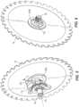
- the saw blade 18 is clamped between opposed flange plates 100A, 100B coupled for co-rotation with the spindle 50.
- the flange plate 100A is axially abutted with an integral flange 102 on the spindle 50.
- the flange plate 100A may alternatively be integrally formed with the flange 102 as a single piece, as shown in FIG. 8A.
- the spindle 50 includes a threaded end to receive a nut 104, which secures the flange plate 100B to the spindle 50 ( FIG. 6 ).
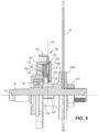
- an actuator 106 is slidably supported for movement via a first bracket 110, which is fastened to the saw unit 42, relative to the spindle 50 in a transverse direction to a longitudinal axis 114 of the spindle 50.
- the actuator 106 is movable between a lockout position (shown as phantom lines in FIG. 8 ) and a release position (shown as solid lines in FIG. 8 ) along an actuator axis 116 that is transverse relative to a longitudinal axis 114 of the spindle 50.
- the actuator 106 is accessible through the opening 22 in the table 14 when a throat plate of the table saw 10 is removed, as shown in FIG. 2 .
- the actuator 106 is biased by a compression spring 108 ( FIG.
- the actuator 106 also includes a tab 122 extending from the first bracket 110 that may be pressed by an operator of the table saw 10 to displace the actuator 106 toward the lockout position, causing a protrusion 126 of the actuator 106 to be received in one of multiple slots 130 in the flange plate 100A adjacent the spindle flange 102. In this manner, rotation of the spindle 50 may be locked to permit the table saw 10 operator to unthread the nut 104 from the spindle 50 to change or remove the saw blade 18.
- the actuator 106 further includes a finger 124 extending away from the actuator axis 116 against which the spring 108 abuts, as described in further detail below.
- the first bracket 110 rotatably supports the spindle 50 relative to the table 14 via bearing 129.
- the first bracket 110 defines a pocket 128 in which the spring 108 is at least partially positioned.
- the spring 108 is interposed between a bottom surface 132 of the pocket 128 and the finger 124 of the actuator 106.
- the finger 124 is abutted against a top surface 133 of the pocket 128 when the actuator 106 is in the release position, preventing further upward movement of the actuator 106.
- the table saw 10 further includes a second bracket 135 attached to the first bracket 110 between which the actuator 106 is held.
- the second bracket 135 defines a slot 137 that laterally constrains movement of the actuator 106, limiting movement of the actuator between the release position and the lockout position to translation within the slot 137 along the axis 116.
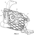
- the table saw 10 further includes a quick-release assembly 134 for attaching and detaching the riving knife 26, to which the blade guard assembly 30 is attached, relative to the table 14.
- the quick-release assembly 134 is mounted to a frame 136 of the saw unit 42. Therefore, the quick-release assembly 134, along with the attached riving knife 26 and blade guard assembly, are vertically and angularly adjustable relative to the table 14 in unison with the saw unit 42.
- the quick-release assembly 134 includes a mounting plate 138 fastened to the saw unit frame 136 for movement therewith and a clamping plate 142 slidable along parallel fasteners 146 ( FIGS. 12 and 13 ) anchored to the mounting plate 138 relative to (i.e., toward and away from) the mounting plate 138.
- the quick-release assembly 134 also includes a pin 154 having a first end 158 attached to the clamping plate 142 for movement therewith and an opposite second end 162 protruding through the mounting plate 138.
- the pin 154 includes a reduced-diameter section 166 ( FIGS. 12 and 13 ) and an adjacent cylindrical section 170, which is adjacent the clamping plate 142. As illustrated in FIG.
- the riving knife 26 includes a vertical slot 174 having a width 178 less than the diameter of the cylindrical section 170 of the pin 154 but greater than the reduced-diameter section 166, and a single aperture 182 coexistent with the slot 174 that has a nominally larger diameter than the cylindrical section 170 of the pin 154.
- the quick-release assembly 134 also includes a compression spring 150 biasing the pin 154 and the attached clamping plate 142 toward a release position, described in detail below, relative to the riving knife 26.
- the quick-release assembly 134 further includes a handle 186 having a cam surface 190.
- the end 162 of the pin 154 is threaded to a barrel nut 188 within the handle, thereby pivotably coupling the pin 154 to the handle 186 about a pivot axis 194.
- the cam surface 190 is in sliding contact with an intermediate bracket 198 which, in turn, is stationary and mounted to the saw unit frame 136.
- the cam surface 190 defines a progressively changing radius of contact R between the pivot axis 194 and the bracket 198, thereby imparting translation to the pin 154 (thus causing spring 150 to compress) as the handle 186 is rotated in a direction coinciding with an increasing radius of contact R.
- the spring 150 rebounds, pushing the pin 154 in an opposite direction.
- the handle 186 is pivoted away from the saw unit frame 136, decreasing the radius of contact R and allowing the spring 150 to rebound and translate the pin 154 (with the attached clamping plate 142) toward the release position shown in FIG. 13 .
- the reduced-diameter section 166 of the pin 154 is aligned with the slot 174 and the cylindrical section 170 is displaced from the aperture 182.
- the clamping plate 142 is displaced from the mounting plate 138, thereby removing the clamping force from the riving knife 26.
- the riving knife 26 may be pulled upward and removed from the table 14. Reattachment of the riving knife 26 is done using the reverse procedure.
Landscapes
- Life Sciences & Earth Sciences (AREA)
- Engineering & Computer Science (AREA)
- Mechanical Engineering (AREA)
- Wood Science & Technology (AREA)
- Forests & Forestry (AREA)
- Sawing (AREA)
- Polishing Bodies And Polishing Tools (AREA)
- Table Devices Or Equipment (AREA)
- Inorganic Insulating Materials (AREA)
Claims (15)
- Scie circulaire à table (10) comprenant :une table (14) ;une unité de scie (42) accouplée de manière mobile sous la table (14) ;un couteau diviseur (26) s'étendant à travers une ouverture (22) dans la table (14) et aligné sur une lame de scie (18) s'étendant à travers l'ouverture (22) ; etun ensemble à libération rapide (134) accouplant sélectivement le couteau diviseur (26) à la table (14), l'ensemble à libération rapide (134) comportantune plaque de montage (138) fixée à un cadre (136) de l'unité de scie (42) pour se déplacer avec elle,une plaque de serrage (142) mobile par rapport à la plaque de montage (138) entre une position de serrage, dans laquelle le couteau diviseur (26) peut être serré entre la plaque de montage (138) et la plaque de serrage (142) pour assujettir le couteau diviseur (26) à la table (14), et une position de libération, dans laquelle le couteau diviseur (26) peut être libéré de la table (14), caractérisé en ce qu'elle comprend :une goupille (154) ayant une première extrémité (158) accouplée pour se déplacer avec la plaque de serrage (142) entre la position de serrage et la position de libération, etune poignée (186) accouplée de manière pivotante à une seconde extrémité de la goupille (154) autour d'un axe de pivotement (194) et comportant une partie came (190) pouvant entrer en prise avec l'unité de scie (42), dans laquelle la plaque de serrage (142) est mobile entre la position de serrage et la position de libération en réponse au mouvement de pivotement de la poignée (186).
- Scie circulaire à table (10) selon la revendication 1, comprenant en outre des fixations parallèles (146) ancrées à la plaque de montage (138) le long desquelles la plaque de serrage (142) peut coulisser par rapport à la plaque de montage (138).
- Scie circulaire à table (10) selon la revendication 1, dans laquelle la goupille (154) comporte en outre une section de diamètre réduit (166) et une section cylindrique adjacente (170) qui est à proximité de la plaque de serrage (142).
- Scie circulaire à table (10) selon la revendication 3, dans laquelle le couteau diviseur (26) comporte une fente verticale (174) ayant une largeur (178) inférieure à un diamètre de la section cylindrique (170) de la goupille (154), mais supérieure à la section de diamètre réduit (166).
- Scie circulaire à table (10) selon la revendication 4, dans laquelle le couteau diviseur (26) comporte en outre une ouverture (182) coexistant avec la fente verticale (174), et dans laquelle l'ouverture (182) comporte un diamètre nominalement plus grand que la section cylindrique (166) de la goupille (154).
- Scie circulaire à table (10) selon la revendication 5, dans laquelle la section cylindrique (170) de la goupille (154) est reçue dans l'ouverture (182) lorsque la plaque de serrage (142) est en position de serrage, verrouillant ainsi le couteau diviseur (26) à la plaque de montage (138) et à l'unité de scie (42).
- Scie circulaire à table (10) selon la revendication 1, dans laquelle l'assemblage à libération rapide (134) comporte en outre un ressort de compression (150) poussant la plaque de serrage (142) vers la position de libération,
ou scie circulaire à table (10) selon la revendication 1, dans laquelle la goupille (154) fait saillie à travers la plaque de montage (138). - Scie circulaire à table (10) selon la revendication 1, dans laquelle la seconde extrémité (162) de la goupille (154) est accouplée de manière pivotante à la poignée (186) autour d'un axe de pivotement (194),et éventuellement, dans laquelle la partie came (190) est en contact coulissant avec un support intermédiaire fixe (198) monté sur l'unité de scie (42),et en outre, éventuellement, dans laquelle la partie came (190) définit un rayon de contact changeant progressivement entre l'axe de pivotement (194) et le support intermédiaire (198), transmettant ainsi une translation à la goupille (154) lorsque la poignée (186) est en rotation dans une direction coïncidant avec un rayon de contact croissant.
- Scie circulaire à table (10) selon la revendication 1, comprenant en outre :une broche (50) accouplée de manière rotative à la table (14) pour entraîner la lame de scie (18) ;au moins une plaque à bride (100A, 100B) accouplée pour une co-rotation avec la broche (50) pour serrer la lame de scie (18) sur la broche (50) ;un actionneur (106) mobile par rapport à la broche (50) entre une position de libération, dans laquelle l'actionneur (106) est désolidarisé de la broche (50), et une position de verrouillage, dans laquelle l'actionneur (106) est en prise avec la broche (50) ou la plaque à bride (100A, 100B) pour empêcher la rotation de la broche (50) afin de faciliter le changement de la lame de scie (18) ; etun ressort (108) qui pousse l'actionneur (106) vers la position de libération.
- Scie circulaire à table (10) selon la revendication 9, dans laquelle l'actionneur (106) est coulissant par rapport à la broche (50) le long d'un axe (116) qui est transversal par rapport à un axe longitudinal (114) de la broche (50).
- Scie circulaire à table (10) selon la revendication 9, dans laquelle l'actionneur (106) comporte une saillie (126) sur une première extrémité qui peut être mise en prise avec la broche (50) ou la plaque à bride (110A, 100B) lorsqu'elle est en position de verrouillage,et éventuellement, dans laquelle l'actionneur (106) comporte une languette (122) sur une seconde extrémité qui peut être manipulée par l'utilisateur pour déplacer l'actionneur (106) de la position de libération vers la position de verrouillage,et en outre, éventuellement, dans laquelle l'actionneur (106) est coulissant par rapport à la broche le long d'un axe (116) qui est transversal par rapport à un axe longitudinal (114) de la broche (50), et dans laquelle la languette (122) est orientée transversalement par rapport à l'axe d'actionneur (116),ou éventuellement, dans laquelle la saillie (126) peut être reçue dans une des multiples fentes (130) définies dans la broche (50) ou la plaque à bride (100A, 100B) pour verrouiller la rotation de la broche (50).
- Scie circulaire à table (10) selon la revendication 9, comprenant en outre un support (198) soutenant de manière rotative la broche (50) par rapport à la table (14), dans laquelle le support (198) définit une poche (128) dans laquelle le ressort (108) est au moins partiellement positionné,et éventuellement, dans laquelle une première extrémité du ressort (108) est appuyée contre une surface inférieure de la poche (132), et dans laquelle une seconde extrémité du ressort (108) est appuyée contre une partie de l'actionneur (106),et en outre, éventuellement, dans laquelle l'actionneur (106) est coulissant par rapport à la broche (50) le long d'un axe (116) qui est transversal par rapport à un axe longitudinal (114) de la broche (50), et dans laquelle l'actionneur (106) comporte un doigt (122) s'étendant à l'écart de l'axe d'actionneur (116) contre lequel la seconde extrémité du ressort (108) est appuyée,et en outre, éventuellement, dans laquelle le doigt (122) vient en butée contre une surface supérieure de la poche (132) lorsque l'actionneur (106) est en position de libération,ou éventuellement, dans laquelle le support (198) est un premier support, et dans laquelle la scie circulaire à table comprend en outre un second support (135) attaché au premier support (198) entre lequel l'actionneur (106) est maintenu,et en outre, éventuellement, dans laquelle au moins l'un parmi le premier support (198) ou le second support (135) définit une fente (137) dans laquelle l'actionneur (106) peut coulisser par rapport à la broche (50) entre la position de libération et la position de verrouillage.
- Scie circulaire à table (10) selon la revendication 9, dans laquelle l'actionneur (106) est positionné sous la table (14),
et éventuellement, dans laquelle l'actionneur (106) est accessible par l'ouverture (122) dans la table (14). - Scie circulaire à table (10) selon la revendication 1, comprenant en outre :un mécanisme de réglage de hauteur de lame (62) permettant d'élever et d'abaisser l'unité de scie (42) par rapport à la table (14), le mécanisme de réglage de hauteur de lame (62) comportantun premier arbre d'entraînement (78) définissant un premier axe de rotation (74) auquel un premier engrenage conique (82) est accouplé pour une co-rotation, etun second arbre d'entraînement (90) définissant un second axe de rotation (94) auquel un second engrenage conique (86) est accouplé pour une co-rotation,dans laquelle le second axe de rotation (94) est perpendiculaire au premier axe de rotation (74), dans laquelle le second arbre d'entraînement (90) est fileté à l'unité de scie (42) de telle sorte que la rotation du second arbre d'entraînement (90) déplace l'unité de scie (42) dans une direction parallèle au second axe de rotation (94),dans laquelle les premier et second engrenages coniques (82, 86) sont engrenés pour transférer un couple du premier arbre d'entraînement (78) au second arbre d'entraînement (90), et dans laquelle un rapport entre des dents du second engrenage conique (86) et des dents du premier engrenage conique (82), respectivement, est compris entre environ 0,5:1 et environ 0,75:1.
- Scie circulaire à table (10) selon la revendication 14, dans laquelle le rapport entre les dents du second engrenage conique (86) et les dents du premier engrenage conique (82) est d'environ 0,52:1,ou la scie circulaire à table (10) selon la revendication 14, dans laquelle le mécanisme de réglage de hauteur de lame (62) comporte en outre un arbre de soutien (98) parallèle au second arbre d'entraînement (90) pour guider la translation de l'unité de scie (42),et éventuellement, dans laquelle l'arbre de soutien (98) est cylindrique et non fileté, permettant ainsi à l'unité de scie (42) de coulisser le long de l'arbre de soutien (98) lorsque les premier et second engrenages coniques (82, 86) sont en rotation,ou la scie circulaire à table (10) selon la revendication 14, comprenant en outre une manivelle (66) accouplée pour une co-rotation avec le premier arbre d'entraînement (78) qui est rotatif autour du premier axe de rotation (74) pour mettre en rotation le premier arbre d'entraînement (78).
Priority Applications (1)
| Application Number | Priority Date | Filing Date | Title |
|---|---|---|---|
| EP24193955.2A EP4434702A3 (fr) | 2017-06-05 | 2018-05-31 | Établi de sciage |
Applications Claiming Priority (2)
| Application Number | Priority Date | Filing Date | Title |
|---|---|---|---|
| CN201720642344.1U CN207189852U (zh) | 2017-06-05 | 2017-06-05 | 台锯 |
| PCT/US2018/035257 WO2018226489A1 (fr) | 2017-06-05 | 2018-05-31 | Établi de sciage |
Related Child Applications (1)
| Application Number | Title | Priority Date | Filing Date |
|---|---|---|---|
| EP24193955.2A Division EP4434702A3 (fr) | 2017-06-05 | 2018-05-31 | Établi de sciage |
Publications (3)
| Publication Number | Publication Date |
|---|---|
| EP3634701A1 EP3634701A1 (fr) | 2020-04-15 |
| EP3634701A4 EP3634701A4 (fr) | 2021-03-10 |
| EP3634701B1 true EP3634701B1 (fr) | 2024-08-21 |
Family
ID=61783949
Family Applications (2)
| Application Number | Title | Priority Date | Filing Date |
|---|---|---|---|
| EP24193955.2A Pending EP4434702A3 (fr) | 2017-06-05 | 2018-05-31 | Établi de sciage |
| EP18812986.0A Active EP3634701B1 (fr) | 2017-06-05 | 2018-05-31 | Établi de sciage |
Family Applications Before (1)
| Application Number | Title | Priority Date | Filing Date |
|---|---|---|---|
| EP24193955.2A Pending EP4434702A3 (fr) | 2017-06-05 | 2018-05-31 | Établi de sciage |
Country Status (6)
| Country | Link |
|---|---|
| US (2) | US10792834B2 (fr) |
| EP (2) | EP4434702A3 (fr) |
| CN (1) | CN207189852U (fr) |
| AU (2) | AU2018280028B2 (fr) |
| TW (1) | TWM568771U (fr) |
| WO (1) | WO2018226489A1 (fr) |
Families Citing this family (16)
| Publication number | Priority date | Publication date | Assignee | Title |
|---|---|---|---|---|
| CN207189852U (zh) * | 2017-06-05 | 2018-04-06 | 米沃奇电动工具公司 | 台锯 |
| US10695847B2 (en) * | 2018-04-09 | 2020-06-30 | Robert Bosch Tool Corporation | Saw height adjustment mechanism having a flexible shaft |
| DE102019200366A1 (de) | 2019-01-14 | 2020-07-16 | Festool Gmbh | Sägeblattabdeckung, Anschlagseinheit und Tischsäge |
| US11383401B2 (en) * | 2019-06-13 | 2022-07-12 | Techtronic Cordless Gp | Table saw |
| US11135664B2 (en) * | 2019-08-27 | 2021-10-05 | Robert Bosch Power Tools GmbH | Table saw with a bevel pivot axis alignment arrangement |
| US11224924B2 (en) * | 2020-01-20 | 2022-01-18 | Robert Benjamin Joiner | Table miter saw |
| CN111560766B (zh) * | 2020-05-21 | 2021-05-28 | 海盐新福莱防水面料股份有限公司 | 一种环保阻燃防水箱包面料切分机的切割刀安装轴 |
| USD956115S1 (en) * | 2020-07-06 | 2022-06-28 | Chao-Ying LEE | Environment control apparatus for cutting machine |
| CN112060211B (zh) * | 2020-09-23 | 2024-09-24 | 淮阴工学院 | 一种基于特斯拉线圈的安全台锯 |
| CN112170950A (zh) * | 2020-09-30 | 2021-01-05 | 广州森宇达科技有限公司 | 一种具有夹紧功能的新材料切割装置 |
| CN112439938B (zh) * | 2020-11-20 | 2021-12-17 | 南宁贝高家具有限公司 | 一种自动上料多角度板材切割机 |
| CN112756677B (zh) * | 2020-12-20 | 2024-01-26 | 广东兴奇新材料有限公司 | 一种铝合金型材加工用切割装置 |
| CN117984392A (zh) * | 2024-01-29 | 2024-05-07 | 南京机电职业技术学院 | 可实现无动力锯切的倒装台锯 |
| DE102024104655A1 (de) * | 2024-02-20 | 2025-08-21 | Werner Selig | Werkzeugmaschine |
| CN118081907B (zh) * | 2024-04-22 | 2024-07-16 | 江苏双金新材料有限公司 | 一种木板自动切割机 |
| CN119704332A (zh) * | 2024-11-25 | 2025-03-28 | 宿迁市吉诺木业有限公司 | 一种环保型锯板机 |
Family Cites Families (396)
| Publication number | Priority date | Publication date | Assignee | Title |
|---|---|---|---|---|
| GB116672A (en) | 1918-02-11 | 1918-06-20 | Thomas Robinson & Son Ltd | Improvements in Circular Saw Benches and Band Re-sawing Machines. |
| GB159707A (en) | 1919-12-31 | 1921-03-10 | Frederick Addison | Improvements in or relating to forming dovetails or the like in wood or other materials, and to machinery or apparatus therefor |
| GB156045A (en) | 1920-05-17 | 1921-01-06 | William Lawes Cole | Improvements in saw benches |
| FR532375A (fr) | 1920-08-13 | 1922-02-02 | Guide pour machines à bois telles que scies à ruban, scies circulaires et analogues | |
| US1496212A (en) | 1923-02-06 | 1924-06-03 | James F Sullivan | Circular-saw guard |
| US1570628A (en) | 1924-10-23 | 1926-01-26 | Flohr Andrew | Saw guard |
| US1649060A (en) | 1925-10-31 | 1927-11-15 | Black & Decker Mfg Co | Portable power-driven rotary tool with spindle latch and handoperated chuck |
| US1672238A (en) * | 1926-08-13 | 1928-06-05 | J D Wallace & Company | Electric handsaw |
| US2211216A (en) | 1938-02-11 | 1940-08-13 | Oster John Mfg Co | Small power driven tool |
| US2466325A (en) | 1945-07-18 | 1949-04-05 | Kearney & Trecker Corp | Saw guard for adjustable-saw saw tables |
| US2744549A (en) | 1953-05-21 | 1956-05-08 | Yates American Machine Co | Precision guide fence for power tool work table |
| US2806493A (en) | 1954-02-05 | 1957-09-17 | King Seeley Corp | Work guide fence |
| US2731049A (en) | 1954-06-10 | 1956-01-17 | Orville C Akin | Saw guard assembly for rotary table saws |
| US2808084A (en) | 1954-12-13 | 1957-10-01 | Yates American Machine Co | Adjustable guide fence for power tool work table |
| US2993518A (en) * | 1958-03-31 | 1961-07-25 | Skil Corp | Portable power driven saw |
| US3013592A (en) | 1959-03-23 | 1961-12-19 | Theodore G Ambrosio | Tilting table saw |
| FR1245976A (fr) | 1960-01-22 | 1960-10-03 | Machine automatique pour la fabrication des tasseaux | |
| US3105530A (en) | 1961-10-23 | 1963-10-01 | Russell E Peterson | Guard for a circular table saw |
| US3229735A (en) | 1963-12-19 | 1966-01-18 | Theron C Parmelee | Folding saw table |
| US3249134A (en) | 1964-01-30 | 1966-05-03 | Wilton Corp | Saw and dado guard |
| GB1274335A (en) | 1970-03-12 | 1972-05-17 | Multico Company Ltd Formerly K | Improvements in or relating to sawing machines and guards therefor |
| US3872951A (en) | 1973-11-06 | 1975-03-25 | Black & Decker Mfg Co | Spindle locking mechanism for rotary power device |
| GB1426348A (en) | 1973-11-12 | 1976-02-25 | Yokoyama Tekko Kk | Automatic lumbering apparatus |
| US3899852A (en) | 1974-08-23 | 1975-08-19 | Singer Co | Spindle drive assembly for a surface-treating machine |
| US4206910A (en) | 1978-06-28 | 1980-06-10 | Biesemeyer William M | Table saw fence system |
| US4206672A (en) | 1978-08-16 | 1980-06-10 | Smith Willis A | Cutting tool jig with cutter guard |
| US4179632A (en) | 1978-12-06 | 1979-12-18 | The Singer Company | Spindle locking mechanism for a rotary power device |
| US4276799A (en) | 1979-04-18 | 1981-07-07 | Black & Decker Inc. | Power tool apparatus |
| US4270427A (en) | 1980-02-04 | 1981-06-02 | Black & Decker Inc. | Bevel angle setting means for a power tool apparatus |
| US4336733A (en) | 1980-06-06 | 1982-06-29 | Macksoud Albert A | Rocking arm saw |
| US4434586A (en) * | 1980-12-03 | 1984-03-06 | Robert Bosch Gmbh | Machine tool, especially a hand-held power tool with a turnable clamping element for clamping a tool on the tool spindle |
| US4385539A (en) | 1981-08-14 | 1983-05-31 | Black & Decker Inc. | Articulated dust cover means for table saw or other power-driven apparatus |
| US4400995A (en) * | 1981-09-23 | 1983-08-30 | Milwaukee Electric Tool Corporation | Spindle lock with impacting capability |
| US4521006A (en) | 1983-01-24 | 1985-06-04 | Waters Deryl P | Removable fence for table saw |
| US4467896A (en) | 1983-06-17 | 1984-08-28 | Black & Decker Inc. | Locking mechanism for a rotary power machine |
| US4489525A (en) | 1983-08-11 | 1984-12-25 | Black & Decker Inc. | Replaceable spindle lock system |
| US4566510A (en) | 1983-11-16 | 1986-01-28 | Shopsmith, Inc. | Workpiece support system for a power tool |
| US4600184A (en) | 1984-01-23 | 1986-07-15 | Delta International Machinery Corp. | Tool fence |
| DE3409731C1 (de) | 1984-03-16 | 1985-08-22 | Peddinghaus, Rolf, Dipl.-Ing., 5828 Ennepetal | Tischkreissäge, insbesondere zum Sägen von Stahlprofilstäben |
| DE3409730C1 (de) | 1984-03-16 | 1985-09-05 | Peddinghaus, Rolf, Dipl.-Ing., 5828 Ennepetal | Tischkreissäge, insbesondere zum Sägen von Stahlprofilstäben |
| US4593590A (en) | 1984-11-19 | 1986-06-10 | Gray Harold Z | Power tool fence |
| DE3447154C2 (de) | 1984-12-22 | 1998-02-19 | Stihl Maschf Andreas | Drehsicherung für ein drehbar gelagertes Werkzeug, insbesondere ein Schneidwerkzeug eines Freischneidegerätes |
| DE3505645A1 (de) | 1985-02-19 | 1986-08-28 | Metabowerke GmbH & Co, 7440 Nürtingen | Tisch, insbesondere saegetisch mit einem verstellbaren anschlag |
| US4599927A (en) | 1985-05-08 | 1986-07-15 | Emerson Electric Co. | Tool elevation and bevel adjustment for direct drive power tool |
| USD293983S (en) | 1985-07-25 | 1988-02-02 | Aldridge Sr Jimmy R | Combined table saw stand, accessory tray and cart |
| US4658687A (en) | 1985-10-08 | 1987-04-21 | Shopsmith, Inc. | Saw fence |
| DE8603369U1 (de) | 1986-02-08 | 1986-04-17 | LESCHA Maschinenfabrik GmbH, 8900 Augsburg | Kreissäge |
| GB8610431D0 (en) | 1986-04-29 | 1986-06-04 | Kango Wolf Power Tools | Rotary power tools |
| EP0253032A1 (fr) | 1986-07-11 | 1988-01-20 | SOCIETE DE MECANIQUE GENERALE (SMG) Société Anonyme dite: | Machine à couper des matériaux de construction |
| DE3644441A1 (de) | 1986-12-24 | 1988-07-07 | Bosch Gmbh Robert | Spanneinrichtung zum loesbaren befestigen eines werkzeuges, insbesondere einer scheibe |
| US4805505A (en) * | 1988-03-02 | 1989-02-21 | John Cantlin | Multi-stop |
| US4846036A (en) | 1988-07-21 | 1989-07-11 | Emerson Electric Co. | Rip fence for table saw |
| US4969496A (en) | 1988-10-21 | 1990-11-13 | Romans Dennis R | Combination electric table saw and folding, mobile work bench |
| US5116249A (en) | 1989-08-11 | 1992-05-26 | Ryobi Limited | Table saw |
| US4909491A (en) | 1989-02-08 | 1990-03-20 | Cheng Wen H | Saw platform and workbench |
| DE4004705A1 (de) | 1989-02-25 | 1990-08-30 | Elektra Beckum Lubitz & Co | Tischkreissaege |
| ES2013536A6 (es) | 1989-06-09 | 1990-05-01 | Boada Germans Sa | Maquina tronzadora para corte de piezas planas de construccion. |
| US4976251A (en) | 1989-06-28 | 1990-12-11 | Smith Allen L | Tile saw apparatus and method |
| US5018563A (en) | 1989-10-17 | 1991-05-28 | Yoder Thomas P | Mobile, extendible table with tool mount and carrier |
| US5018562A (en) | 1989-12-21 | 1991-05-28 | Adams Phillip A | Power tool fence system |
| EP0438611B1 (fr) | 1990-01-20 | 1993-12-29 | Dolmar GmbH | Dispositif d'immobilisation en rotation pour un organe rotatif, notamment pour un outil de coupe |
| DE4100412A1 (de) * | 1991-01-09 | 1992-07-16 | Bosch Gmbh Robert | Elektrische handdrehwerkzeugmaschine, insbesondere handkreissaege |
| US5158001A (en) | 1991-08-09 | 1992-10-27 | Skil Corporation | Power table tool assemblies with dust collection system |
| US5174349A (en) | 1991-08-09 | 1992-12-29 | Skil Corporation | Power table saw assemblies having integral spare part storage |
| US5159864A (en) | 1991-09-23 | 1992-11-03 | Wedemeyer Arlan B | Insert for a table saw |
| US5161590A (en) | 1992-01-27 | 1992-11-10 | Otto David L | Miter saw table apparatus |
| US5289897A (en) | 1992-10-22 | 1994-03-01 | Wiehe Jr William H | Sawbuck including vierendeel truss construction |
| US5439073A (en) | 1992-10-30 | 1995-08-08 | Johnson; Richard | Foldaway splay-legged stand |
| GB2273078A (en) | 1992-12-04 | 1994-06-08 | Black & Decker Inc | Adjustable riving knife |
| US5320150A (en) | 1992-12-22 | 1994-06-14 | Ryobi America Corp. | Collapsible stand |
| DE4306763A1 (de) | 1993-03-04 | 1994-09-08 | Inotech Spezialmaschinen Gmbh | Kreissäge mit einem Sägetisch |
| GB9304539D0 (en) | 1993-03-05 | 1993-04-21 | Black & Decker Inc | A device having a flange lock |
| DE4329410A1 (de) | 1993-09-01 | 1995-03-02 | Otto Bergler | Tisch und Gehrungssäge für mobile Anwendung |
| CA2148974A1 (fr) | 1994-05-13 | 1995-11-14 | Richard P. Brault | Mecanisme de table tournante destine a un outil de coupe |
| US5542639A (en) | 1994-06-08 | 1996-08-06 | Delta International Machinery Corp. | Flat folding support |
| WO1996000638A1 (fr) | 1994-06-29 | 1996-01-11 | Trevor Tisdall | Etabli a scie |
| DE4424022A1 (de) | 1994-07-08 | 1996-01-18 | Metabowerke Kg | Arretiervorrichtung für die Antriebsspindel von Handwerkzeugmaschinen |
| DE4424615B4 (de) | 1994-07-13 | 2008-03-20 | Elumatec Gmbh & Co. Kg | Untertisch-Gehrungssäge |
| US5460070A (en) | 1994-10-05 | 1995-10-24 | Buskness; Earl C. | Fence for table saws |
| GB9425390D0 (en) | 1994-12-12 | 1995-02-15 | Black & Decker Inc | A double bevel table saw |
| GB2295987A (en) | 1994-12-12 | 1996-06-19 | Black & Decker Inc | A bevel table saw adjusting mechanism |
| EP0799115B1 (fr) | 1994-12-21 | 1999-03-03 | Jens Ole Madsen | Dispositif de rangement, de preference pour outils, et accessoires destines a etre montes sur ledit dispositif |
| DE29501506U1 (de) | 1995-02-01 | 1995-03-23 | Chen, Ruey-Zon, Taichung | Justiervorrichtung für ein Sägeblatt einer Motorsäge |
| US5619896A (en) | 1995-06-27 | 1997-04-15 | Chen; Ruey Z. | Base of a sawing machine |
| DE29514074U1 (de) | 1995-09-01 | 1995-10-19 | Atika-Maschinenfabrik Wilhelm Pollmeier GmbH & Co, 59227 Ahlen | Tischkreissäge |
| US5722308A (en) | 1995-10-10 | 1998-03-03 | Black & Decker Inc. | Movable fence for a machine tool |
| GB9604420D0 (en) | 1996-03-01 | 1996-05-01 | Black & Decker Inc | A bevel table saw |
| DE19620323C1 (de) | 1996-05-21 | 1997-10-09 | Lutz Eugen Masch | Gehrungssäge |
| US6276064B1 (en) | 1996-05-31 | 2001-08-21 | Black & Decker, Inc. | Viewing window for saw guard and method of making same |
| US5794351A (en) | 1996-05-31 | 1998-08-18 | Black & Decker, Inc. | Window assembly and lower saw guard for circular saw |
| US5822864A (en) | 1996-05-31 | 1998-10-20 | Black & Decker, Inc. | Viewing window for circular saw guard |
| SE507264C2 (sv) | 1996-06-13 | 1998-05-04 | Atlas Copco Tools Ab | Handhållet motordrivet verktyg |
| US5875698A (en) | 1996-06-17 | 1999-03-02 | Black & Decker Inc. | Blade and motor carrier with height/angle adjustment mechanism |
| US5778953A (en) | 1996-07-22 | 1998-07-14 | Trojan Manufacturing, Inc. | Method and apparatus for carrying and supporting a portable bench top saw |
| US5857507A (en) | 1996-09-20 | 1999-01-12 | Black & Decker Inc. | Table saw |
| DE29616862U1 (de) | 1996-09-27 | 1996-11-14 | Fa. Andreas Stihl, 71336 Waiblingen | Drehsicherung für ein drehend gelagertes Werkzeug eines Arbeitsgerätes |
| JP3404517B2 (ja) | 1997-06-19 | 2003-05-12 | 株式会社マキタ | テーブルソー |
| US6070229A (en) | 1997-12-02 | 2000-05-30 | Sandcraft, Inc. | Cache memory cell with a pre-programmed state |
| TW467783B (en) | 1998-02-13 | 2001-12-11 | Black & Amp Decker Inc | Table saw |
| US6899004B1 (en) | 1998-08-14 | 2005-05-31 | Delta International Machinery Corp. | Sawing apparatus and saw fence system |
| CA2276499C (fr) | 1998-08-19 | 2004-10-26 | Sommerville Design & Manufacturing Inc. | Separateur de scie circulaire avec dispositif antirecul integre |
| US5970835A (en) | 1998-09-10 | 1999-10-26 | Black & Decker Inc. | Throat plate for a tool |
| DE29817589U1 (de) | 1998-10-02 | 2000-02-17 | Elektra Beckum Ag, 49716 Meppen | Werkzeugmaschine, insbesondere transportable Tischkreissäge |
| US6796208B1 (en) | 1999-02-19 | 2004-09-28 | Matthew Roy Jorgensen | Sawdust collection hood for table saw |
| DE29904915U1 (de) | 1999-03-17 | 1999-08-12 | Ant. Panhans GmbH Werkzeug- und Maschinenfabrik, 72488 Sigmaringen | Kreissäge |
| US6578461B1 (en) | 1999-05-18 | 2003-06-17 | Larry Y. S. Loo | Saw fence and work feed apparatus |
| US6109157A (en) * | 1999-06-09 | 2000-08-29 | S-B Power Tool Company | Arbor locking mechanism |
| TW494057B (en) | 1999-06-09 | 2002-07-11 | Sb Power Tool Co | Table saw and rip fence for use with a table saw |
| US6182935B1 (en) | 1999-06-09 | 2001-02-06 | S-B Power Tool Company | Folding table for use with a table saw |
| US6530303B1 (en) | 1999-06-10 | 2003-03-11 | Black & Decker Inc. | Table saw |
| US6725755B1 (en) | 1999-06-15 | 2004-04-27 | S-B Power Tool Company | Scale system for use with a movable table |
| US6485360B1 (en) | 1999-07-20 | 2002-11-26 | Hutchins Mfg, Co. | Orbital sanding tool |
| US8646369B2 (en) | 2007-10-01 | 2014-02-11 | Sd3, Llc | Table saw guards, splitter assemblies, accessories, and table saws including the same |
| US20060219076A1 (en) | 2005-03-31 | 2006-10-05 | Gass Stephen F | Table saw throat plates and table saws including the same |
| US20050139056A1 (en) | 2003-12-31 | 2005-06-30 | Gass Stephen F. | Fences for table saws |
| US8246059B2 (en) | 2008-02-29 | 2012-08-21 | Sd3, Llc | Mobile base for a table saw |
| US7707920B2 (en) | 2003-12-31 | 2010-05-04 | Sd3, Llc | Table saws with safety systems |
| US10967536B2 (en) | 2011-02-17 | 2021-04-06 | Sawstop Holding Llc | Blade guard for a table saw |
| US10589366B2 (en) | 2010-02-19 | 2020-03-17 | Sawstop Holding Llc | Table saw insert with lock-down mechanism |
| US7827890B2 (en) | 2004-01-29 | 2010-11-09 | Sd3, Llc | Table saws with safety systems and systems to mount and index attachments |
| US10022811B2 (en) | 2009-07-31 | 2018-07-17 | Sawstop Holding Llc | Dust collection system for a table saw |
| US6435460B1 (en) | 1999-11-04 | 2002-08-20 | Van Mark Products Corporation | Portable tool support stand |
| DE29922107U1 (de) | 1999-12-16 | 2000-02-17 | Hilti Ag, Schaan | Handkreissäge |
| US6360797B1 (en) | 1999-12-28 | 2002-03-26 | One World Technologies, Inc. | Power tool and portable support assembly |
| US6578856B2 (en) | 2000-01-10 | 2003-06-17 | W. Scott Kahle | Collapsible portable saw stand |
| US6314893B1 (en) | 2000-01-26 | 2001-11-13 | Wy Peron Lee | Table frame for cutting machine |
| US6986370B1 (en) | 2000-02-01 | 2006-01-17 | Home Depot U.S.A., Inc. | Table saw |
| DE10017981A1 (de) | 2000-04-11 | 2001-10-25 | Bosch Gmbh Robert | Werkzeugaufnahme |
| DE10040334A1 (de) | 2000-08-17 | 2002-02-28 | Hilti Ag | Elektrowerkzeug mit Arretiervorrichtung |
| US7168502B2 (en) * | 2000-08-17 | 2007-01-30 | Hilti Aktiengesellschaft | Electric power tool with locking mechanism |
| DE10048675A1 (de) | 2000-09-30 | 2002-04-18 | Festool Gmbh | Handwerkzeugmaschine |
| US6647847B2 (en) | 2001-02-15 | 2003-11-18 | Htc Products, Inc. | Fence |
| US6736042B2 (en) | 2001-03-01 | 2004-05-18 | Porter-Cable Corporation | Work piece guiding system for a table saw |
| US20020179181A1 (en) | 2001-06-04 | 2002-12-05 | Murphy William Charles | Portable, lockable, folding work bench or tool table |
| TW498831U (en) | 2001-06-15 | 2002-08-11 | Ruei-Sen Liau | Bits and chips discharging device for desktop saw fixture |
| US6502493B1 (en) | 2001-06-27 | 2003-01-07 | Emerson Electric Co. | Table saw blade heel adjuster |
| US6745804B2 (en) | 2001-07-11 | 2004-06-08 | Black & Decker Inc. | Portable work bench |
| CN1547521A (zh) | 2001-07-11 | 2004-11-17 | �����˺ʹ��˹�˾ | 动力工具安全机构 |
| EP1930128A3 (fr) | 2001-07-11 | 2008-08-20 | Black & Decker, Inc. | Établi portable |
| DE20119835U1 (de) | 2001-12-06 | 2003-04-10 | Robert Bosch Gmbh, 70469 Stuttgart | Handwerkzeugmaschine mit Spindelstop |
| WO2003064115A1 (fr) | 2002-01-30 | 2003-08-07 | Wolfcraft Gmbh | Support pliable pour scie pendulaire |
| US6736044B2 (en) | 2002-10-07 | 2004-05-18 | Chin-Chin Chang | Table saw having a blade suspension structure |
| US20050160895A1 (en) | 2002-10-31 | 2005-07-28 | Garcia Jaime E. | Dual bevel table saw |
| US7137327B2 (en) | 2002-10-31 | 2006-11-21 | Black & Decker Inc. | Riving knife assembly for a dual bevel table saw |
| US20040118261A1 (en) | 2002-10-31 | 2004-06-24 | Garcia Jaime E. | Dual bevel table saw |
| US6722618B1 (en) | 2002-11-11 | 2004-04-20 | Chervon International Trading Co., Ltd. | Foldable support frame for supporting cutting machine |
| EP1422033B1 (fr) | 2002-11-22 | 2009-01-14 | Otto Martin Maschinenbau GmbH & Co. | Scie à panneaux avec guide |
| US20040250901A1 (en) | 2002-12-02 | 2004-12-16 | Mike Ursell | Collapsible stand |
| US7234380B2 (en) | 2003-01-27 | 2007-06-26 | Black & Decker Inc. | Side pressure splitter |
| USD486504S1 (en) | 2003-02-21 | 2004-02-10 | Durq Machinery Corp. | Saw table having foldable stand |
| US20060096428A1 (en) | 2003-03-14 | 2006-05-11 | Garcia Jaime E | Riving knife assembly |
| US20040187666A1 (en) | 2003-03-25 | 2004-09-30 | Durq Machinery Corp. | Table saw |
| SE525836C2 (sv) | 2003-03-31 | 2005-05-10 | Atlas Copco Tools Ab | Slipmaskin med sprängskydd och spindellåsning |
| US6974370B2 (en) | 2003-05-16 | 2005-12-13 | Hutchins Manufacturing Company | Spindle lock for an orbital abrading or polishing tool |
| US20040255745A1 (en) | 2003-06-23 | 2004-12-23 | One World Technologies Limited | Table saw guard assembly |
| US20070186741A1 (en) | 2003-06-23 | 2007-08-16 | Buck William C | Table saw guard assembly |
| TW577382U (en) | 2003-06-30 | 2004-02-21 | Ruei-Sen Liau | Guiding board adjustment apparatus for desktop sawing machine |
| CN2649283Y (zh) | 2003-07-17 | 2004-10-20 | 南京泉峰国际贸易有限公司 | 用于切割机器的可折叠支架 |
| US20060101958A1 (en) | 2003-07-31 | 2006-05-18 | Garcia Jaime E | Table saw |
| DE10337853A1 (de) | 2003-08-18 | 2005-03-17 | Robert Bosch Gmbh | Handwerkzeugmaschine |
| DE10338651A1 (de) | 2003-08-22 | 2005-03-31 | Robert Bosch Gmbh | Tischkreissägemaschine |
| US7131364B2 (en) | 2003-08-25 | 2006-11-07 | Eastway Fair Company, Ltd. | Collapsible stand for a bench-top power tool |
| JP2005088248A (ja) * | 2003-09-12 | 2005-04-07 | Makita Corp | 動力工具 |
| US20050092155A1 (en) | 2003-09-17 | 2005-05-05 | Phillips William J. | Power tool and components therefor |
| US6942229B2 (en) | 2003-10-31 | 2005-09-13 | One World Technologies Limited | Collapsible stand for a bench-top power tool |
| US7293488B2 (en) | 2003-11-04 | 2007-11-13 | Henry Wang | Splitter for circular table saw and method of installation |
| US7086434B2 (en) | 2003-12-04 | 2006-08-08 | Wy Peron Lee | Docking frame for power saw machine |
| TWM248546U (en) | 2003-12-17 | 2004-11-01 | Durq Machinery Corp | Stands for supporting sawing and cutting beds |
| CN2686797Y (zh) | 2003-12-26 | 2005-03-23 | 圣杰机器工业股份有限公司 | 用于支撑锯切机台的脚架 |
| US7980325B2 (en) | 2004-01-16 | 2011-07-19 | Credo Technology Corporation | Rotating shaft locking mechanism |
| US7066069B2 (en) | 2004-03-09 | 2006-06-27 | Rexon Industrial Corp., Ltd. | Tilt angle display device for a circular saw machine |
| FR2867410B1 (fr) | 2004-03-09 | 2006-09-08 | Paul Parisse | Table pour le sciage et la decoupe de panneaux ou analogues |
| US7540223B2 (en) * | 2004-03-12 | 2009-06-02 | Makita Corporation | Mountings for riving knives of table saws |
| JP4617091B2 (ja) | 2004-03-16 | 2011-01-19 | 株式会社マキタ | 切断機におけるライビングナイフの取り付け具 |
| US8096519B2 (en) | 2004-03-12 | 2012-01-17 | Robert Bosch Gmbh | Collapsible rolling support stand |
| TWM254327U (en) | 2004-03-16 | 2005-01-01 | Durq Machinery Corp | Saw bench with scale system |
| US20060101968A1 (en) | 2004-03-18 | 2006-05-18 | Chuck Baird | Table saw trunnion system |
| TWM251667U (en) | 2004-03-22 | 2004-12-01 | Durq Machinery Corp | Table saw |
| US7665393B2 (en) | 2004-04-22 | 2010-02-23 | Black & Decker Inc. | Table saw guard |
| US20060101966A1 (en) | 2004-05-06 | 2006-05-18 | Garcia Jaime E | Alignment system coupling apparatus and method |
| DE202004009166U1 (de) | 2004-06-09 | 2004-09-09 | Proxxon S.A. | Auflageerweiterung für eine Tischkreissäge |
| US20060011191A1 (en) | 2004-07-13 | 2006-01-19 | Elmer Vavricek | Tile saw stand |
| GB2416147B (en) | 2004-07-14 | 2008-03-19 | Turner Intellect Property Ltd | Wet wheel cutter |
| JP2006068940A (ja) | 2004-08-31 | 2006-03-16 | Makita Corp | 切断機のキックバック防止装置 |
| US7213829B2 (en) | 2004-09-24 | 2007-05-08 | Super Made Products Co., Ltd. | Table saw cart |
| US7077421B2 (en) | 2004-09-24 | 2006-07-18 | Super Made Products Co., Ltd. | Table saw cart |
| TWM270864U (en) | 2004-10-11 | 2005-07-21 | Rexon Ind Corp Ltd | Gauge apparatus for table saw machine |
| US7475621B2 (en) | 2004-11-02 | 2009-01-13 | Henry Wang | Kerf control apparatus for a table saw |
| CN2756419Y (zh) | 2004-12-07 | 2006-02-08 | 青岛地恩地机电科技股份有限公司 | 台锯物料挡板的微调装置 |
| CN2756420Y (zh) | 2004-12-07 | 2006-02-08 | 青岛地恩地机电科技股份有限公司 | 台锯物料挡板的延伸微调装置 |
| DE202004019137U1 (de) | 2004-12-09 | 2005-05-04 | Metabowerke Gmbh | Kapp- und Tischkreissäge |
| DE102005010354B4 (de) | 2005-03-08 | 2013-03-07 | Wolfcraft Gmbh | Zusammenfaltbarer Kappsägenständer |
| CN1830634A (zh) | 2005-03-08 | 2006-09-13 | 绍博有限公司 | 工具车 |
| US7287453B2 (en) | 2005-03-10 | 2007-10-30 | Sheng-Hsien Kuo | Woodworking table with an auxiliary device |
| US8006596B2 (en) | 2005-03-11 | 2011-08-30 | Walter Meier (Manufacturing) Inc. | Cutting tool and parts and accessories therefor |
| US20060201300A1 (en) | 2005-03-11 | 2006-09-14 | Schwaiger Barry M | Cutting tool and parts and accessories therefor |
| US20060201302A1 (en) | 2005-03-11 | 2006-09-14 | Schwaiger Barry M | Cutting tool and parts and accessories therefor |
| TWM272659U (en) | 2005-04-01 | 2005-08-11 | Durq Machinery Corp | Calibrating structure for saw blade of platform saw |
| GB2425281B (en) | 2005-04-22 | 2007-12-05 | Rexon Ind Corp Ltd | Tilt angle display device for a circular saw machine |
| DE202005006816U1 (de) | 2005-04-28 | 2005-07-21 | Rexon Industrial Corp., Ltd., Tali | Kreissägemaschine mit Neigungswinkel-Anzeigevorrichtung |
| US7930960B2 (en) | 2005-05-06 | 2011-04-26 | Allen Ip, Incorporated | Universal machinery fence system |
| TWM277546U (en) | 2005-05-13 | 2005-10-11 | Durq Machinery Corp | Platform saw having clamping mechanism |
| US7302878B2 (en) | 2005-05-21 | 2007-12-04 | P & F Brother Industrial Corporation | Protective cover device for a sawing machine |
| DE102005024111B3 (de) | 2005-05-25 | 2006-08-10 | Georg Aigner | Anschlaglineal für Tischkreissägen |
| US7128641B1 (en) | 2005-06-08 | 2006-10-31 | Gison Machinery Co., Ltd. | Grinder capable of seizing rotary shaft |
| US7374184B2 (en) | 2005-06-17 | 2008-05-20 | Worthy Michael W | Portable table for table saw |
| TWM288234U (en) | 2005-08-29 | 2006-03-01 | Rexon Ind Corp Ltd | Table saw machine |
| TWI274641B (en) | 2005-08-30 | 2007-03-01 | Rexon Ind Corp Ltd | Cutting machine |
| CN100396987C (zh) | 2005-09-05 | 2008-06-25 | 墩丰机械工业股份有限公司 | 移动式工具机脚架 |
| DE202005014115U1 (de) | 2005-09-07 | 2006-01-05 | Felder Kg | Holzbearbeitungsmaschine mit einem Holzbearbeitungswerkzeug und einer Auflagefläche |
| CN2908087Y (zh) * | 2005-09-09 | 2007-06-06 | 余锡辉 | 可随圆锯片升降的劈刀结构 |
| JP2007076235A (ja) | 2005-09-15 | 2007-03-29 | Makita Corp | 切断機 |
| US20070074613A1 (en) | 2005-10-04 | 2007-04-05 | Ben Yu | Worktable having adjustable shield |
| US7278646B2 (en) | 2005-10-07 | 2007-10-09 | Bor-Yann Chuang | Movable table stand |
| US7299730B2 (en) | 2005-10-11 | 2007-11-27 | Hummel Joseph S | Saw calibration wheel |
| TWM291355U (en) | 2005-10-12 | 2006-06-01 | Rexon Ind Corp Ltd | Circular saw |
| US7210386B1 (en) * | 2005-11-02 | 2007-05-01 | Kingsand Machinery Ltd. | Quickly detachable protective cover unit of a table sawing machine |
| TWM289693U (en) | 2005-11-14 | 2006-04-21 | Durq Machinery Corp | Angle adjusting device for a tablesaw machine |
| US7600456B2 (en) | 2005-11-21 | 2009-10-13 | Robert Bosch Gmbh | Modular guard system for a power saw |
| US7437981B2 (en) | 2005-11-21 | 2008-10-21 | Robert Bosch Gmbh | Modular guard system and apparatus for a power saw |
| US20070163408A1 (en) | 2006-01-17 | 2007-07-19 | Buck William C | Table saw guard |
| TW200730315A (en) | 2006-02-08 | 2007-08-16 | Rexon Ind Corp Ltd | Indicating device of sawing and cutting machine |
| US20070186739A1 (en) | 2006-02-16 | 2007-08-16 | Eastway Fair Company Limited Of Trident Chambers | Riving knife clamp for a table saw |
| DE102006010433B4 (de) | 2006-03-03 | 2008-11-13 | Scheppach Fabrikation Von Holzbearbeitungsmaschinen Gmbh | Holzbearbeitungsmaschine mit einem Schwenkrahmen |
| ATE424270T1 (de) | 2006-04-11 | 2009-03-15 | Black & Decker Inc | Tischanschlag für eine gehrungssäge mit oberplatte |
| US8584564B2 (en) | 2006-04-21 | 2013-11-19 | Black & Decker Inc. | Table saw |
| ITMI20061115A1 (it) | 2006-06-09 | 2007-12-10 | Guido Valentini | Dispositivo di bloccaggio dell'albero mandrino di un utensile motorizzato |
| DE202006009307U1 (de) | 2006-06-12 | 2006-08-31 | Metabowerke Gmbh | Maschinenständer |
| US20080006133A1 (en) * | 2006-07-05 | 2008-01-10 | Bor-Yann Chuang | Saw blade disassembling device for a table saw |
| US20080014844A1 (en) | 2006-07-17 | 2008-01-17 | James Matthew Pontieri | Power tool with spindle lock |
| GB0615150D0 (en) | 2006-07-29 | 2006-09-06 | Black & Decker Inc | Mitre saw with top table |
| US20080047410A1 (en) * | 2006-08-25 | 2008-02-28 | Bor-Yann Chuang | Quickly collapsible dividing plate base unit for a table sawing machine |
| CN200948584Y (zh) | 2006-09-18 | 2007-09-19 | 泉峰(中国)贸易有限公司 | 一种工作台 |
| TW200815168A (en) | 2006-09-18 | 2008-04-01 | Durq Machinery Corp | Folding structure for supporting table type tool |
| US7988538B2 (en) | 2006-10-13 | 2011-08-02 | Black & Decker Inc. | Large angle grinder |
| US20080092710A1 (en) | 2006-10-20 | 2008-04-24 | Bor-Yann Chuang | Locking device for a rotary shaft of a table saw |
| TWI312720B (en) | 2006-11-08 | 2009-08-01 | Rexon Ind Corp Ltd | Connecting assembly |
| JP4954680B2 (ja) | 2006-11-21 | 2012-06-20 | 株式会社マキタ | 電動工具用作業台 |
| TW200823029A (en) | 2006-11-29 | 2008-06-01 | Durq Machinery Corp | Quick release structure and guard assembly of table saw using same |
| CN101204804B (zh) * | 2006-12-21 | 2011-09-07 | 苏州宝时得电动工具有限公司 | 动力工具 |
| US20080156162A1 (en) | 2006-12-29 | 2008-07-03 | Bor-Yann Chuang | Saw blade protecting plate for a table sawing machine |
| NL1033187C2 (nl) | 2007-01-08 | 2008-07-09 | Bosch Gmbh Robert | Elektrisch gereedschap, zoals een haakse slijper. |
| US7543614B2 (en) | 2007-03-13 | 2009-06-09 | Wise Robert W | Collapsible infeed/outfeed table |
| JP5009011B2 (ja) | 2007-03-15 | 2012-08-22 | 株式会社マキタ | 切断機 |
| US20080271583A1 (en) | 2007-05-04 | 2008-11-06 | Bor-Yann Chuang | Fence for a table saw |
| CA2588894A1 (fr) | 2007-05-16 | 2008-11-16 | Darrin Eugene Smith | Surface de travail pour machine ou etabli |
| CN201030506Y (zh) | 2007-05-21 | 2008-03-05 | 吴世雄 | 一种改进的角向磨光机 |
| US20080289469A1 (en) | 2007-05-24 | 2008-11-27 | Bor-Yann Chuang | Sawing angle sensing device for a sawing machine |
| CN201046517Y (zh) | 2007-05-30 | 2008-04-16 | 巨庭机械股份有限公司 | 台锯机分割座组的止逆板快拆构造 |
| JP4981526B2 (ja) | 2007-06-07 | 2012-07-25 | 株式会社マキタ | 切断機における割り刃の支持構造 |
| CN101342677B (zh) | 2007-07-11 | 2011-08-03 | 苏州宝时得电动工具有限公司 | 手持式动力工具 |
| CN201067860Y (zh) | 2007-07-12 | 2008-06-04 | 苏州宝时得电动工具有限公司 | 手持式动力工具 |
| DE602008002502D1 (de) | 2007-07-16 | 2010-10-28 | Black & Decker Inc | Tischsäge |
| US7921755B2 (en) | 2007-07-16 | 2011-04-12 | Black & Decker Inc. | Guard assembly for table saw |
| TW200904609A (en) | 2007-07-26 | 2009-02-01 | Rexon Ind Corp Ltd | Quick-release structure for covering part of rotary sawing machine |
| US20090051097A1 (en) | 2007-08-22 | 2009-02-26 | Bor-Yann Chuang | Quickly assembled and disassembled non-return plate for a table sawing machine |
| TW200909168A (en) | 2007-08-31 | 2009-03-01 | Rexon Ind Corp Ltd | Protection cover assembly for circular saw and quick release structure thereof |
| DE102007042722A1 (de) | 2007-09-07 | 2009-03-12 | Robert Bosch Gmbh | Handwerkzeugmaschine mit Spindelarretierung |
| CN101398121A (zh) | 2007-09-30 | 2009-04-01 | 力山工业股份有限公司 | 用于机具的支撑架 |
| CN101406972B (zh) | 2007-10-09 | 2013-06-19 | 力山工业股份有限公司 | 用于圆锯机的护盖组件及其快拆结构 |
| CN201105344Y (zh) | 2007-10-22 | 2008-08-27 | 巨庭机械股份有限公司 | 快速组拆的止逆板 |
| US7475622B1 (en) * | 2007-10-26 | 2009-01-13 | P & F Brother Industrial Corporation | Supporting device for mounting a protective cover to shield a cutting blade of a cutting machine |
| CN201120639Y (zh) | 2007-10-30 | 2008-09-24 | 巨庭机械股份有限公司 | 台锯机的可调式劈刀板 |
| DE102007055650B3 (de) | 2007-11-21 | 2009-04-16 | Metabowerke Gmbh | Motorisch angetriebene Handkreissäge mit verdrehbarer Schutzhaube |
| US7882870B2 (en) | 2007-11-23 | 2011-02-08 | Wy Peron Lee | Portable supporting frame for cutting machine |
| US8047242B2 (en) | 2007-12-07 | 2011-11-01 | Black & Decker Inc. | Power tool with spindle lock |
| CN101450400B (zh) | 2007-12-07 | 2011-05-18 | 苏州宝时得电动工具有限公司 | 台式工具 |
| US20090158905A1 (en) | 2007-12-21 | 2009-06-25 | Bor-Yann Chuang | Swiftly collapsible check plate unit for a table saw |
| EP2075078B1 (fr) | 2007-12-29 | 2014-07-16 | Positec Power Tools (Suzhou) Co., Ltd. | Scie à table |
| US20090223337A1 (en) * | 2008-03-06 | 2009-09-10 | Black & Decker Inc. | Worm drive saw |
| JP5225783B2 (ja) | 2008-03-11 | 2013-07-03 | 株式会社マキタ | 切断機の鋸刃ガード装置 |
| DE102008000851A1 (de) | 2008-03-27 | 2009-10-01 | Robert Bosch Gmbh | Werkzeugmaschine, insbesondere Unterflur-Tischkreissäge |
| CN201175941Y (zh) | 2008-04-10 | 2009-01-07 | 姚振昇 | 一种圆锯截板机 |
| US20090266212A1 (en) * | 2008-04-29 | 2009-10-29 | Mao Shan Machinery Industrial Co., Ltd. | Saw blade dismantling and positioning structure of sawing machine |
| DE102008001727A1 (de) | 2008-05-13 | 2009-11-19 | Robert Bosch Gmbh | Werkzeugmaschine |
| US20090288303A1 (en) * | 2008-05-23 | 2009-11-26 | P & F Brother Industrial Corporation | Supporting device for mounting a protective cover to shield a cutting blade of a cutting machine |
| US20090293693A1 (en) | 2008-05-29 | 2009-12-03 | Yi-Te Liao | Workpiece splitting and kickback-inhibiting assembly for a table cutting machine |
| US8042794B2 (en) | 2008-07-02 | 2011-10-25 | Black & Decker Inc. | Workbench with saw horse |
| US20100011929A1 (en) | 2008-07-16 | 2010-01-21 | Iannelli Sr Joseph | Power-saw cross-cut, miter-cut, and rip-cut assembly |
| TW201010829A (en) | 2008-09-08 | 2010-03-16 | Mobiletron Electronics Co Ltd | Automatic screw feeding apparatus for electricity powered screwdriver |
| DE202008011969U1 (de) | 2008-09-09 | 2008-12-24 | Scheppach Fabrikation Von Holzbearbeitungsmaschinen Gmbh | Kreissäge |
| US10870216B2 (en) | 2008-09-30 | 2020-12-22 | Black & Decker Inc. | Table saws having integrated control systems |
| US8464994B2 (en) | 2008-10-22 | 2013-06-18 | Rexon Industrial Corp., Ltd. | Folding tool stand |
| TW201016360A (en) | 2008-10-27 | 2010-05-01 | Rexon Ind Corp Ltd | Quick release device for sawing machine |
| TW201016422A (en) | 2008-10-27 | 2010-05-01 | Rexon Ind Corp Ltd | Safety device for saw machine |
| TW201016420A (en) | 2008-10-27 | 2010-05-01 | Rexon Ind Corp Ltd | Quick-release device of saw machine |
| TW201016362A (en) | 2008-10-27 | 2010-05-01 | Rexon Ind Corp Ltd | Quick release device for sawing machine |
| TW201016361A (en) | 2008-10-27 | 2010-05-01 | Rexon Ind Corp Ltd | Quick release device for sawing machine |
| TWI402123B (zh) | 2008-10-31 | 2013-07-21 | Durq Machinery Corp | Work platform for table saws |
| TW201018558A (en) | 2008-11-10 | 2010-05-16 | Durq Machinery Corp | Quick release structure of eye protecting cover of table saw |
| US8234959B2 (en) | 2008-11-19 | 2012-08-07 | Robert Bosch Gmbh | Table saw fence |
| US20110072950A1 (en) | 2008-11-20 | 2011-03-31 | Iannelli Sr Joseph A | Cross-cut, rip-cut, compound-miter, table saw combination |
| TW201020049A (en) * | 2008-11-21 | 2010-06-01 | Durq Machinery Corp | Rapid chopper dismount mechanism of table saw |
| CN101745960B (zh) | 2008-11-28 | 2012-07-18 | 力山工业股份有限公司 | 锯切机的安全装置 |
| CN101745692A (zh) | 2008-11-28 | 2010-06-23 | 圣杰机器工业股份有限公司 | 桌锯的劈刀快拆结构 |
| TW201021945A (en) | 2008-12-02 | 2010-06-16 | Durq Machinery Corp | Saw blade adjusting structure of table saw |
| TWI366638B (en) | 2009-02-20 | 2012-06-21 | Rexon Ind Corp Ltd | Mobile tool stand |
| US20100224044A1 (en) | 2009-03-04 | 2010-09-09 | P & F Brother Industrial Corporation | Protective cover assembly with a quick release mechanism |
| TWM362095U (en) | 2009-03-05 | 2009-08-01 | Oav Equipment & Amp Tools Inc | Quick disassembling assembly for blade of rotary sawing machine |
| JP2010221389A (ja) | 2009-03-25 | 2010-10-07 | Makita Corp | 上部テーブル付卓上丸鋸 |
| US8011444B2 (en) | 2009-04-03 | 2011-09-06 | Ingersoll Rand Company | Spindle locking assembly |
| US20100269656A1 (en) | 2009-04-28 | 2010-10-28 | Credo Technology Corporation | Table saw with symmetrical rail fence storage capability |
| US8424434B2 (en) | 2009-04-28 | 2013-04-23 | Robert Bosch Gmbh | Universal fence for a power table saw |
| US20100319509A1 (en) | 2009-06-22 | 2010-12-23 | Bor-Yann Chuang | Quick release device for a chopper in a workbench sawing machine |
| US8601926B2 (en) | 2009-07-20 | 2013-12-10 | Robert Bosch Gmbh | Portable table saw having a durable sub-frame |
| US8418591B2 (en) | 2009-07-24 | 2013-04-16 | Robert Bosch Gmbh | Power table saw with extension table |
| US8272305B2 (en) | 2009-07-27 | 2012-09-25 | Nanjing Haiwei Machinery Co., Ltd. | Multi-gear synchro-moving riving knife system with quick release device |
| US20110039482A1 (en) | 2009-07-29 | 2011-02-17 | Terry Timmons | Grinder |
| US20110041667A1 (en) | 2009-08-20 | 2011-02-24 | Pei-Fang Chiang | Mechanism for adjusting blade height of bench saw |
| US8312799B2 (en) | 2009-08-31 | 2012-11-20 | Robert Bosch Gmbh | Rip fence with a roller-type activation mechanism |
| CN201505767U (zh) * | 2009-09-10 | 2010-06-16 | 廖慧兰 | 台锯机的刀板快拆机构 |
| US9254580B2 (en) | 2009-09-15 | 2016-02-09 | Robert Bosch Gmbh | Guard system for a power saw |
| DE202009012444U1 (de) | 2009-09-16 | 2011-02-10 | Wilhelm Altendorf Gmbh & Co. Kg | Formatkreissäge mit Direktantrieb |
| US20110067540A1 (en) | 2009-09-24 | 2011-03-24 | Credo Technology Corporation | Table saw with movable table and stationary rip fence |
| TWI359729B (en) * | 2009-09-29 | 2012-03-11 | Rexon Ind Corp Ltd | A saw machine riving knife adjustment mechanism |
| CN102029562A (zh) | 2009-09-29 | 2011-04-27 | 周海涛 | 一种角磨机机头 |
| CN201544103U (zh) | 2009-09-29 | 2010-08-11 | 周海涛 | 一种角磨机机头 |
| US20110100183A1 (en) | 2009-11-03 | 2011-05-05 | John Tomaino | Table saw blade height and angle adjustment mechanism |
| US20110146470A1 (en) | 2009-12-17 | 2011-06-23 | Kun-Yen Lin | Woodworking Machine with Sensing Device |
| TWI379753B (en) * | 2009-12-30 | 2012-12-21 | Rexon Ind Corp Ltd | A saw machine riving knife adjustment mechanism |
| US9434089B2 (en) | 2010-01-13 | 2016-09-06 | Chin-Yuan Liu | Anti-kickback device for a table saw machine |
| US9919369B2 (en) | 2013-10-17 | 2018-03-20 | Sawstop Holding Llc | Inserts for table saws |
| US8215215B2 (en) | 2010-03-10 | 2012-07-10 | Bor-Yann Chuang | Protective cover structure of a desk sawing machine |
| GB201008829D0 (en) | 2010-05-27 | 2010-07-14 | Evolution Power Tools Ltd | Mitre saw |
| US20110296968A1 (en) | 2010-06-02 | 2011-12-08 | Robert Bosch Gmbh | Feedback mechanism for adjustable miter fence |
| US8376307B2 (en) | 2010-06-03 | 2013-02-19 | Robert Bosch Gmbh | Foldable stand for a portable power tool |
| US8474358B2 (en) | 2010-06-23 | 2013-07-02 | Robert Bosch Gmbh | Pull rod release mechanism for a push-pull table tool |
| US8967027B2 (en) | 2010-07-02 | 2015-03-03 | Robert Bosch Gmbh | Modular table system for table saws |
| TW201201937A (en) | 2010-07-07 | 2012-01-16 | Durq Machinery Corp | Material blocking device for table sawing machine |
| US8616104B2 (en) | 2010-07-12 | 2013-12-31 | Robert Bosch Gmbh | Portable table saw |
| US20120055307A1 (en) | 2010-09-02 | 2012-03-08 | Burke Jeremy J | Table Saw Having a Removable Face Fence |
| US20120187272A1 (en) | 2011-01-26 | 2012-07-26 | P & F Brother Industrial Corporation | Wheeled Collapsible Stand for a Power Driven Machine |
| CN102615340B (zh) | 2011-01-28 | 2014-10-08 | 苏州宝时得电动工具有限公司 | 台锯 |
| CN102615341B (zh) | 2011-01-28 | 2014-10-08 | 苏州宝时得电动工具有限公司 | 台锯 |
| CN102615338B (zh) | 2011-01-28 | 2014-07-02 | 苏州宝时得电动工具有限公司 | 台锯 |
| CN102632479B (zh) | 2011-02-14 | 2014-12-31 | 力山工业股份有限公司 | 锯切机的护盖快拆装置及组拆方法 |
| US20120222534A1 (en) | 2011-03-03 | 2012-09-06 | Robert Bosch Gmbh | Bevel adjustment for a push-pull table saw |
| CN202053121U (zh) | 2011-03-29 | 2011-11-30 | 浙江金磐机电实业有限公司 | 一种改进的角向磨光机 |
| GB2490787B (en) | 2011-05-11 | 2015-02-11 | Cggveritas Services Sa | Compact broadband source and method |
| CN102773558B (zh) | 2011-05-12 | 2016-09-07 | 力山工业股份有限公司 | 桌锯机的锯片护盖装置 |
| DE202011101566U1 (de) | 2011-05-30 | 2012-09-05 | Wilhelm Altendorf Gmbh & Co. Kg | Holzbearbeitungsmaschine mit Sägeblatt-Schnellabsenkung |
| US9149926B2 (en) | 2011-06-17 | 2015-10-06 | Rexon Industrial Corp., Ltd. | Collapsible stand |
| US9776262B2 (en) | 2011-10-14 | 2017-10-03 | Robert Bosch Tool Corporation | Table saw with foldable tabletop and handle |
| DE102011085411A1 (de) | 2011-10-28 | 2013-05-02 | Robert Bosch Gmbh | Sägemaschine, insbesondere Kreissägemaschine |
| GB2496405A (en) | 2011-11-10 | 2013-05-15 | Black & Decker Inc | Guard to surround mitre saw blade when lowered towards table |
| GB2496406A (en) | 2011-11-10 | 2013-05-15 | Black & Decker Inc | Guard mounted on inclining structure of mitre saw |
| GB2497352A (en) | 2011-12-09 | 2013-06-12 | Black & Decker Inc | Height Adjustment Mechanism for Top Table of Mitre and Table saw |
| GB2497347A (en) | 2011-12-09 | 2013-06-12 | Black & Decker Inc | Chop Saw with top Table Saw |
| CN102581883A (zh) | 2012-03-12 | 2012-07-18 | 周五祥 | 便携式折叠木工推锯台 |
| DE102012204802A1 (de) | 2012-03-26 | 2013-09-26 | Metabowerke Gmbh | Maschinenuntergestell |
| US8991806B2 (en) | 2012-04-19 | 2015-03-31 | John Matthew Meyer | Extension table assembly for power tools |
| EP2869976B1 (fr) | 2012-07-04 | 2017-02-22 | Robert Bosch GmbH | Dispositif d'arrêt de broche |
| US9844891B2 (en) | 2012-07-20 | 2017-12-19 | Sawstop Holding Llc | Blade tilt mechanisms for table saws |
| US9555491B2 (en) | 2012-07-20 | 2017-01-31 | Sd3, Llc | Blade elevation mechanisms and anti-backdrive mechanisms for table saws |
| CN202861959U (zh) | 2012-10-15 | 2013-04-10 | 浙江凯顺工具有限公司 | 角磨机的齿轮锁定机构 |
| CN203003256U (zh) | 2012-11-28 | 2013-06-19 | 金华市亚虎工具有限公司 | 可调斜断锯工作台 |
| US9333638B2 (en) | 2012-11-30 | 2016-05-10 | Robert Bosch Gmbh | Power tool including an anti-tilt structure for an accessory |
| US9592623B2 (en) | 2012-12-26 | 2017-03-14 | Robert Bosch Tool Corporation | Rip fence having dual adjustment for a power tool |
| US9216518B2 (en) | 2012-12-27 | 2015-12-22 | Robert Bosch Gmbh | Power equipment with quick release anti-kickback device |
| US20140182430A1 (en) | 2012-12-31 | 2014-07-03 | Robert Bosch Gmbh | Saw Device with Detection System |
| US9272439B2 (en) | 2012-12-31 | 2016-03-01 | Robert Bosch Gmbh | Rip fence for a table saw having independent alignment and locking |
| DE102013102091A1 (de) | 2013-03-04 | 2014-09-04 | Sebastian Hilz | Mobile Sägevorrichtung |
| EP2969340B1 (fr) | 2013-03-13 | 2021-11-17 | Robert Bosch GmbH | Scie de table à onglets |
| US9873158B2 (en) | 2013-03-13 | 2018-01-23 | Robert Bosch Tool Corporation | Adjustment and control features for a power tool |
| EP2969420B1 (fr) | 2013-03-13 | 2019-05-08 | Robert Bosch GmbH | Mécanisme de réglage de hauteur pour outil électrique |
| US9517516B2 (en) | 2013-03-14 | 2016-12-13 | Robert Bosch Tool Corporation | Blade drop power tool with dust management |
| US20140261367A1 (en) | 2013-03-15 | 2014-09-18 | Techtronic Power Tools Technology Limited | Portable tile saw |
| WO2014151111A1 (fr) | 2013-03-15 | 2014-09-25 | Robert Bosch Gmbh | Guide longitudinal à triple action de verrouillage |
| CN203197885U (zh) | 2013-04-22 | 2013-09-18 | 浙江工商职业技术学院 | 一种多功能工作台 |
| US9731362B2 (en) | 2013-08-14 | 2017-08-15 | Black & Decker Inc. | Table saw |
| CN203357138U (zh) | 2013-08-19 | 2013-12-25 | 浙江华丰电动工具有限公司 | 防护罩快锁装置 |
| US9095989B2 (en) | 2013-09-05 | 2015-08-04 | Chin-Chin Chang | Rip fence with lockng mechanisms |
| US9327355B2 (en) | 2013-10-08 | 2016-05-03 | John Struss | Universal portable work station |
| US9186734B2 (en) | 2013-10-16 | 2015-11-17 | Chin-Chin Chang | Height adjustment mechanism of table saw |
| US10118308B2 (en) * | 2013-10-17 | 2018-11-06 | Sawstop Holding Llc | Systems to mount and index riving knives and spreaders in table saws |
| US9757871B2 (en) | 2013-10-17 | 2017-09-12 | Sd3, Llc | Fences for table saws |
| CN203542570U (zh) | 2013-10-22 | 2014-04-16 | 南京工业职业技术学院 | 一种多功能钳工台 |
| US10092968B2 (en) | 2013-11-01 | 2018-10-09 | Sawstop Holding Llc | Table saws |
| US10442107B2 (en) | 2013-11-12 | 2019-10-15 | Sawstop Holding Llc | Control systems for power tools |
| WO2015102909A1 (fr) | 2013-12-30 | 2015-07-09 | Robert Bosch Gmbh | Système d'écoulement d'air et d'éclairage pour un banc de scie |
| TWI542435B (zh) | 2014-01-07 | 2016-07-21 | Durq Machinery Corp | Supporting the folding structure of the countertop tool |
| CN203875992U (zh) | 2014-04-28 | 2014-10-15 | 江苏金飞达电动工具有限公司 | 护罩快速取出装置 |
| US9186736B1 (en) | 2014-05-18 | 2015-11-17 | Chin-Chin Chang | Collapsible stand for table saw |
| US20150343662A1 (en) | 2014-05-29 | 2015-12-03 | Black & Decker Inc. | Table saws having integrated control systems |
| WO2016040442A1 (fr) | 2014-09-09 | 2016-03-17 | Robert Bosch Gmbh | Verrouillage de calibre à onglet pour scies sur table coulissantes |
| US20160067800A1 (en) | 2014-09-09 | 2016-03-10 | Robert Bosch Gmbh | Table Top and Throat Plate for Power Table Saws |
| EP3191272A4 (fr) * | 2014-09-09 | 2018-02-07 | Robert Bosch GmbH | Agencement de montage de couteau diviseur pour scie sur table |
| US20160082529A1 (en) | 2014-09-22 | 2016-03-24 | Sd3, Llc | Blade elevation mechanisms and anti-backdrive mechanisms for table saws |
| US10384366B2 (en) | 2014-09-29 | 2019-08-20 | Lowe's Companies, Inc. | Push-sticks for saws and storage systems thereof |
| EP3224009B1 (fr) | 2014-11-24 | 2021-08-04 | Nanjing Chervon Industry Co., Ltd. | Améliorations apportées à des scies circulaires à table portables |
| CN107708946B (zh) | 2014-12-03 | 2021-07-13 | 罗伯特·博世有限公司 | 便携式台锯 |
| TWI570348B (zh) | 2014-12-16 | 2017-02-11 | 力山工業股份有限公司 | 可收折之支撐架 |
| CN204414058U (zh) | 2015-02-03 | 2015-06-24 | 金华市亚虎工具有限公司 | 折叠型斜断锯工作台 |
| TWI546488B (zh) | 2015-02-03 | 2016-08-21 | 力山工業股份有限公司 | 可收折腳架 |
| CN207189852U (zh) * | 2017-06-05 | 2018-04-06 | 米沃奇电动工具公司 | 台锯 |
| CN207310105U (zh) * | 2017-09-18 | 2018-05-04 | 广东泰坤建设工程有限公司 | 木工圆盘锯 |
-
2017
- 2017-06-05 CN CN201720642344.1U patent/CN207189852U/zh active Active
-
2018
- 2018-04-09 US US15/947,985 patent/US10792834B2/en active Active
- 2018-05-28 TW TW107207002U patent/TWM568771U/zh not_active IP Right Cessation
- 2018-05-31 EP EP24193955.2A patent/EP4434702A3/fr active Pending
- 2018-05-31 EP EP18812986.0A patent/EP3634701B1/fr active Active
- 2018-05-31 AU AU2018280028A patent/AU2018280028B2/en active Active
- 2018-05-31 WO PCT/US2018/035257 patent/WO2018226489A1/fr not_active Ceased
-
2020
- 2020-09-01 US US17/008,845 patent/US11407142B2/en active Active
-
2021
- 2021-12-09 AU AU2021282494A patent/AU2021282494B2/en active Active
Also Published As
| Publication number | Publication date |
|---|---|
| US20200391404A1 (en) | 2020-12-17 |
| WO2018226489A1 (fr) | 2018-12-13 |
| EP4434702A2 (fr) | 2024-09-25 |
| EP3634701A4 (fr) | 2021-03-10 |
| AU2018280028B2 (en) | 2021-09-09 |
| EP4434702A3 (fr) | 2025-03-05 |
| AU2021282494A1 (en) | 2022-01-06 |
| AU2018280028A1 (en) | 2020-01-16 |
| EP3634701A1 (fr) | 2020-04-15 |
| TWM568771U (zh) | 2018-10-21 |
| US20180345526A1 (en) | 2018-12-06 |
| AU2021282494B2 (en) | 2023-09-21 |
| US10792834B2 (en) | 2020-10-06 |
| CN207189852U (zh) | 2018-04-06 |
| US11407142B2 (en) | 2022-08-09 |
Similar Documents
| Publication | Publication Date | Title |
|---|---|---|
| US11407142B2 (en) | Table saw | |
| AU2005201541B2 (en) | Toolless adjustable jigsaw base | |
| US5802943A (en) | Bevel locking system for a sliding compound miter saw | |
| EP1256407B1 (fr) | Scie à onglet du type combiné contenir une table avec un système d'indexage et un système de bloquage | |
| US5040444A (en) | Saw blade position setting apparatus | |
| EP2217399B1 (fr) | Ensemble de verrouillage d'onglet pour scies à onglets | |
| US20070074612A1 (en) | Worktable having adjustable shield | |
| EP2753446B1 (fr) | Scie à onglet avec entrainement par double courroie | |
| DE102012217532B4 (de) | Sägenanordnung | |
| US7013781B2 (en) | Bevel locking system for a sliding compound miter saw | |
| US8266996B2 (en) | Adjustable fence assembly for a miter saw | |
| EP0891241B1 (fr) | Dispositifs de securite et de commande pour scie a onglets combines coulissants | |
| US20070214928A1 (en) | Miter Saw | |
| CA2636054A1 (fr) | Machine outil rotative | |
| US20080145167A1 (en) | Cutting machine | |
| CN121821511A (zh) | 台锯 | |
| CN119502032A (zh) | 一种印制线路板用双向v割机 |
Legal Events
| Date | Code | Title | Description |
|---|---|---|---|
| STAA | Information on the status of an ep patent application or granted ep patent |
Free format text: STATUS: THE INTERNATIONAL PUBLICATION HAS BEEN MADE |
|
| PUAI | Public reference made under article 153(3) epc to a published international application that has entered the european phase |
Free format text: ORIGINAL CODE: 0009012 |
|
| STAA | Information on the status of an ep patent application or granted ep patent |
Free format text: STATUS: REQUEST FOR EXAMINATION WAS MADE |
|
| 17P | Request for examination filed |
Effective date: 20191202 |
|
| AK | Designated contracting states |
Kind code of ref document: A1 Designated state(s): AL AT BE BG CH CY CZ DE DK EE ES FI FR GB GR HR HU IE IS IT LI LT LU LV MC MK MT NL NO PL PT RO RS SE SI SK SM TR |
|
| AX | Request for extension of the european patent |
Extension state: BA ME |
|
| DAV | Request for validation of the european patent (deleted) | ||
| DAX | Request for extension of the european patent (deleted) | ||
| A4 | Supplementary search report drawn up and despatched |
Effective date: 20210205 |
|
| RIC1 | Information provided on ipc code assigned before grant |
Ipc: B27B 5/32 20060101ALI20210201BHEP Ipc: B27B 5/22 20060101AFI20210201BHEP |
|
| STAA | Information on the status of an ep patent application or granted ep patent |
Free format text: STATUS: EXAMINATION IS IN PROGRESS |
|
| 17Q | First examination report despatched |
Effective date: 20221031 |
|
| GRAP | Despatch of communication of intention to grant a patent |
Free format text: ORIGINAL CODE: EPIDOSNIGR1 |
|
| STAA | Information on the status of an ep patent application or granted ep patent |
Free format text: STATUS: GRANT OF PATENT IS INTENDED |
|
| INTG | Intention to grant announced |
Effective date: 20240229 |
|
| GRAS | Grant fee paid |
Free format text: ORIGINAL CODE: EPIDOSNIGR3 |
|
| GRAA | (expected) grant |
Free format text: ORIGINAL CODE: 0009210 |
|
| STAA | Information on the status of an ep patent application or granted ep patent |
Free format text: STATUS: THE PATENT HAS BEEN GRANTED |
|
| AK | Designated contracting states |
Kind code of ref document: B1 Designated state(s): AL AT BE BG CH CY CZ DE DK EE ES FI FR GB GR HR HU IE IS IT LI LT LU LV MC MK MT NL NO PL PT RO RS SE SI SK SM TR |
|
| REG | Reference to a national code |
Ref country code: GB Ref legal event code: FG4D |
|
| REG | Reference to a national code |
Ref country code: CH Ref legal event code: EP |
|
| REG | Reference to a national code |
Ref country code: DE Ref legal event code: R096 Ref document number: 602018073414 Country of ref document: DE |
|
| REG | Reference to a national code |
Ref country code: IE Ref legal event code: FG4D |
|
| REG | Reference to a national code |
Ref country code: LT Ref legal event code: MG9D |
|
| REG | Reference to a national code |
Ref country code: NL Ref legal event code: MP Effective date: 20240821 |
|
| PG25 | Lapsed in a contracting state [announced via postgrant information from national office to epo] |
Ref country code: NO Free format text: LAPSE BECAUSE OF FAILURE TO SUBMIT A TRANSLATION OF THE DESCRIPTION OR TO PAY THE FEE WITHIN THE PRESCRIBED TIME-LIMIT Effective date: 20241121 |
|
| REG | Reference to a national code |
Ref country code: AT Ref legal event code: MK05 Ref document number: 1715110 Country of ref document: AT Kind code of ref document: T Effective date: 20240821 |
|
| PG25 | Lapsed in a contracting state [announced via postgrant information from national office to epo] |
Ref country code: NL Free format text: LAPSE BECAUSE OF FAILURE TO SUBMIT A TRANSLATION OF THE DESCRIPTION OR TO PAY THE FEE WITHIN THE PRESCRIBED TIME-LIMIT Effective date: 20240821 Ref country code: PL Free format text: LAPSE BECAUSE OF FAILURE TO SUBMIT A TRANSLATION OF THE DESCRIPTION OR TO PAY THE FEE WITHIN THE PRESCRIBED TIME-LIMIT Effective date: 20240821 Ref country code: PT Free format text: LAPSE BECAUSE OF FAILURE TO SUBMIT A TRANSLATION OF THE DESCRIPTION OR TO PAY THE FEE WITHIN THE PRESCRIBED TIME-LIMIT Effective date: 20241223 Ref country code: GR Free format text: LAPSE BECAUSE OF FAILURE TO SUBMIT A TRANSLATION OF THE DESCRIPTION OR TO PAY THE FEE WITHIN THE PRESCRIBED TIME-LIMIT Effective date: 20241122 Ref country code: FI Free format text: LAPSE BECAUSE OF FAILURE TO SUBMIT A TRANSLATION OF THE DESCRIPTION OR TO PAY THE FEE WITHIN THE PRESCRIBED TIME-LIMIT Effective date: 20240821 |
|
| PG25 | Lapsed in a contracting state [announced via postgrant information from national office to epo] |
Ref country code: BG Free format text: LAPSE BECAUSE OF FAILURE TO SUBMIT A TRANSLATION OF THE DESCRIPTION OR TO PAY THE FEE WITHIN THE PRESCRIBED TIME-LIMIT Effective date: 20240821 |
|
| PG25 | Lapsed in a contracting state [announced via postgrant information from national office to epo] |
Ref country code: LV Free format text: LAPSE BECAUSE OF FAILURE TO SUBMIT A TRANSLATION OF THE DESCRIPTION OR TO PAY THE FEE WITHIN THE PRESCRIBED TIME-LIMIT Effective date: 20240821 |
|
| PG25 | Lapsed in a contracting state [announced via postgrant information from national office to epo] |
Ref country code: IS Free format text: LAPSE BECAUSE OF FAILURE TO SUBMIT A TRANSLATION OF THE DESCRIPTION OR TO PAY THE FEE WITHIN THE PRESCRIBED TIME-LIMIT Effective date: 20241221 Ref country code: AT Free format text: LAPSE BECAUSE OF FAILURE TO SUBMIT A TRANSLATION OF THE DESCRIPTION OR TO PAY THE FEE WITHIN THE PRESCRIBED TIME-LIMIT Effective date: 20240821 |
|
| PG25 | Lapsed in a contracting state [announced via postgrant information from national office to epo] |
Ref country code: HR Free format text: LAPSE BECAUSE OF FAILURE TO SUBMIT A TRANSLATION OF THE DESCRIPTION OR TO PAY THE FEE WITHIN THE PRESCRIBED TIME-LIMIT Effective date: 20240821 |
|
| PG25 | Lapsed in a contracting state [announced via postgrant information from national office to epo] |
Ref country code: ES Free format text: LAPSE BECAUSE OF FAILURE TO SUBMIT A TRANSLATION OF THE DESCRIPTION OR TO PAY THE FEE WITHIN THE PRESCRIBED TIME-LIMIT Effective date: 20240821 Ref country code: RS Free format text: LAPSE BECAUSE OF FAILURE TO SUBMIT A TRANSLATION OF THE DESCRIPTION OR TO PAY THE FEE WITHIN THE PRESCRIBED TIME-LIMIT Effective date: 20241121 |
|
| PG25 | Lapsed in a contracting state [announced via postgrant information from national office to epo] |
Ref country code: RS Free format text: LAPSE BECAUSE OF FAILURE TO SUBMIT A TRANSLATION OF THE DESCRIPTION OR TO PAY THE FEE WITHIN THE PRESCRIBED TIME-LIMIT Effective date: 20241121 Ref country code: PT Free format text: LAPSE BECAUSE OF FAILURE TO SUBMIT A TRANSLATION OF THE DESCRIPTION OR TO PAY THE FEE WITHIN THE PRESCRIBED TIME-LIMIT Effective date: 20241223 Ref country code: PL Free format text: LAPSE BECAUSE OF FAILURE TO SUBMIT A TRANSLATION OF THE DESCRIPTION OR TO PAY THE FEE WITHIN THE PRESCRIBED TIME-LIMIT Effective date: 20240821 Ref country code: NO Free format text: LAPSE BECAUSE OF FAILURE TO SUBMIT A TRANSLATION OF THE DESCRIPTION OR TO PAY THE FEE WITHIN THE PRESCRIBED TIME-LIMIT Effective date: 20241121 Ref country code: NL Free format text: LAPSE BECAUSE OF FAILURE TO SUBMIT A TRANSLATION OF THE DESCRIPTION OR TO PAY THE FEE WITHIN THE PRESCRIBED TIME-LIMIT Effective date: 20240821 Ref country code: LV Free format text: LAPSE BECAUSE OF FAILURE TO SUBMIT A TRANSLATION OF THE DESCRIPTION OR TO PAY THE FEE WITHIN THE PRESCRIBED TIME-LIMIT Effective date: 20240821 Ref country code: IS Free format text: LAPSE BECAUSE OF FAILURE TO SUBMIT A TRANSLATION OF THE DESCRIPTION OR TO PAY THE FEE WITHIN THE PRESCRIBED TIME-LIMIT Effective date: 20241221 Ref country code: HR Free format text: LAPSE BECAUSE OF FAILURE TO SUBMIT A TRANSLATION OF THE DESCRIPTION OR TO PAY THE FEE WITHIN THE PRESCRIBED TIME-LIMIT Effective date: 20240821 Ref country code: GR Free format text: LAPSE BECAUSE OF FAILURE TO SUBMIT A TRANSLATION OF THE DESCRIPTION OR TO PAY THE FEE WITHIN THE PRESCRIBED TIME-LIMIT Effective date: 20241122 Ref country code: FI Free format text: LAPSE BECAUSE OF FAILURE TO SUBMIT A TRANSLATION OF THE DESCRIPTION OR TO PAY THE FEE WITHIN THE PRESCRIBED TIME-LIMIT Effective date: 20240821 Ref country code: ES Free format text: LAPSE BECAUSE OF FAILURE TO SUBMIT A TRANSLATION OF THE DESCRIPTION OR TO PAY THE FEE WITHIN THE PRESCRIBED TIME-LIMIT Effective date: 20240821 Ref country code: BG Free format text: LAPSE BECAUSE OF FAILURE TO SUBMIT A TRANSLATION OF THE DESCRIPTION OR TO PAY THE FEE WITHIN THE PRESCRIBED TIME-LIMIT Effective date: 20240821 Ref country code: AT Free format text: LAPSE BECAUSE OF FAILURE TO SUBMIT A TRANSLATION OF THE DESCRIPTION OR TO PAY THE FEE WITHIN THE PRESCRIBED TIME-LIMIT Effective date: 20240821 |
|
| PG25 | Lapsed in a contracting state [announced via postgrant information from national office to epo] |
Ref country code: SM Free format text: LAPSE BECAUSE OF FAILURE TO SUBMIT A TRANSLATION OF THE DESCRIPTION OR TO PAY THE FEE WITHIN THE PRESCRIBED TIME-LIMIT Effective date: 20240821 Ref country code: RO Free format text: LAPSE BECAUSE OF FAILURE TO SUBMIT A TRANSLATION OF THE DESCRIPTION OR TO PAY THE FEE WITHIN THE PRESCRIBED TIME-LIMIT Effective date: 20240821 Ref country code: DK Free format text: LAPSE BECAUSE OF FAILURE TO SUBMIT A TRANSLATION OF THE DESCRIPTION OR TO PAY THE FEE WITHIN THE PRESCRIBED TIME-LIMIT Effective date: 20240821 |
|
| PG25 | Lapsed in a contracting state [announced via postgrant information from national office to epo] |
Ref country code: EE Free format text: LAPSE BECAUSE OF FAILURE TO SUBMIT A TRANSLATION OF THE DESCRIPTION OR TO PAY THE FEE WITHIN THE PRESCRIBED TIME-LIMIT Effective date: 20240821 |
|
| PG25 | Lapsed in a contracting state [announced via postgrant information from national office to epo] |
Ref country code: CZ Free format text: LAPSE BECAUSE OF FAILURE TO SUBMIT A TRANSLATION OF THE DESCRIPTION OR TO PAY THE FEE WITHIN THE PRESCRIBED TIME-LIMIT Effective date: 20240821 |
|
| PG25 | Lapsed in a contracting state [announced via postgrant information from national office to epo] |
Ref country code: IT Free format text: LAPSE BECAUSE OF FAILURE TO SUBMIT A TRANSLATION OF THE DESCRIPTION OR TO PAY THE FEE WITHIN THE PRESCRIBED TIME-LIMIT Effective date: 20240821 Ref country code: SK Free format text: LAPSE BECAUSE OF FAILURE TO SUBMIT A TRANSLATION OF THE DESCRIPTION OR TO PAY THE FEE WITHIN THE PRESCRIBED TIME-LIMIT Effective date: 20240821 |
|
| REG | Reference to a national code |
Ref country code: DE Ref legal event code: R097 Ref document number: 602018073414 Country of ref document: DE |
|
| PLBE | No opposition filed within time limit |
Free format text: ORIGINAL CODE: 0009261 |
|
| STAA | Information on the status of an ep patent application or granted ep patent |
Free format text: STATUS: NO OPPOSITION FILED WITHIN TIME LIMIT |
|
| PGFP | Annual fee paid to national office [announced via postgrant information from national office to epo] |
Ref country code: DE Payment date: 20250529 Year of fee payment: 8 |
|
| PGFP | Annual fee paid to national office [announced via postgrant information from national office to epo] |
Ref country code: GB Payment date: 20250527 Year of fee payment: 8 |
|
| 26N | No opposition filed |
Effective date: 20250522 |
|
| PG25 | Lapsed in a contracting state [announced via postgrant information from national office to epo] |
Ref country code: SE Free format text: LAPSE BECAUSE OF FAILURE TO SUBMIT A TRANSLATION OF THE DESCRIPTION OR TO PAY THE FEE WITHIN THE PRESCRIBED TIME-LIMIT Effective date: 20240821 |
|
| REG | Reference to a national code |
Ref country code: CH Ref legal event code: H13 Free format text: ST27 STATUS EVENT CODE: U-0-0-H10-H13 (AS PROVIDED BY THE NATIONAL OFFICE) Effective date: 20251223 |
|
| PG25 | Lapsed in a contracting state [announced via postgrant information from national office to epo] |
Ref country code: LU Free format text: LAPSE BECAUSE OF NON-PAYMENT OF DUE FEES Effective date: 20250531 |
|
| PG25 | Lapsed in a contracting state [announced via postgrant information from national office to epo] |
Ref country code: CH Free format text: LAPSE BECAUSE OF NON-PAYMENT OF DUE FEES Effective date: 20250531 |
|
| REG | Reference to a national code |
Ref country code: BE Ref legal event code: MM Effective date: 20250531 |
|
| PG25 | Lapsed in a contracting state [announced via postgrant information from national office to epo] |
Ref country code: MC Free format text: LAPSE BECAUSE OF FAILURE TO SUBMIT A TRANSLATION OF THE DESCRIPTION OR TO PAY THE FEE WITHIN THE PRESCRIBED TIME-LIMIT Effective date: 20240821 |
|
| PG25 | Lapsed in a contracting state [announced via postgrant information from national office to epo] |
Ref country code: IE Free format text: LAPSE BECAUSE OF NON-PAYMENT OF DUE FEES Effective date: 20250531 |
|
| PG25 | Lapsed in a contracting state [announced via postgrant information from national office to epo] |
Ref country code: BE Free format text: LAPSE BECAUSE OF NON-PAYMENT OF DUE FEES Effective date: 20250531 |
|
| PG25 | Lapsed in a contracting state [announced via postgrant information from national office to epo] |
Ref country code: FR Free format text: LAPSE BECAUSE OF NON-PAYMENT OF DUE FEES Effective date: 20250531 |