EP3634702B1 - Zapfenloch- und zapfenschneidvorrichtung - Google Patents
Zapfenloch- und zapfenschneidvorrichtung Download PDFInfo
- Publication number
- EP3634702B1 EP3634702B1 EP18814193.1A EP18814193A EP3634702B1 EP 3634702 B1 EP3634702 B1 EP 3634702B1 EP 18814193 A EP18814193 A EP 18814193A EP 3634702 B1 EP3634702 B1 EP 3634702B1
- Authority
- EP
- European Patent Office
- Prior art keywords
- tenon
- guide
- mortise
- support plate
- router
- Prior art date
- Legal status (The legal status is an assumption and is not a legal conclusion. Google has not performed a legal analysis and makes no representation as to the accuracy of the status listed.)
- Active
Links
Images






Classifications
-
- B—PERFORMING OPERATIONS; TRANSPORTING
- B23—MACHINE TOOLS; METAL-WORKING NOT OTHERWISE PROVIDED FOR
- B23Q—DETAILS, COMPONENTS, OR ACCESSORIES FOR MACHINE TOOLS, e.g. ARRANGEMENTS FOR COPYING OR CONTROLLING; MACHINE TOOLS IN GENERAL CHARACTERISED BY THE CONSTRUCTION OF PARTICULAR DETAILS OR COMPONENTS; COMBINATIONS OR ASSOCIATIONS OF METAL-WORKING MACHINES, NOT DIRECTED TO A PARTICULAR RESULT
- B23Q9/00—Arrangements for supporting or guiding portable metal-working machines or apparatus
- B23Q9/0014—Portable machines provided with or cooperating with guide means supported directly by the workpiece during action
-
- B—PERFORMING OPERATIONS; TRANSPORTING
- B27—WORKING OR PRESERVING WOOD OR SIMILAR MATERIAL; NAILING OR STAPLING MACHINES IN GENERAL
- B27C—PLANING, DRILLING, MILLING, TURNING OR UNIVERSAL MACHINES FOR WOOD OR SIMILAR MATERIAL
- B27C5/00—Machines designed for producing special profiles or shaped work, e.g. by rotary cutters; Equipment therefor
- B27C5/10—Portable hand-operated wood-milling machines; Routers
-
- B—PERFORMING OPERATIONS; TRANSPORTING
- B27—WORKING OR PRESERVING WOOD OR SIMILAR MATERIAL; NAILING OR STAPLING MACHINES IN GENERAL
- B27F—DOVETAILED WORK; TENONS; SLOTTING MACHINES FOR WOOD OR SIMILAR MATERIAL; NAILING OR STAPLING MACHINES
- B27F1/00—Dovetailed work; Tenons; Making tongues or grooves; Groove- and- tongue jointed work; Finger- joints
- B27F1/08—Making dovetails, tongues, or tenons, of definite limited length
-
- B—PERFORMING OPERATIONS; TRANSPORTING
- B27—WORKING OR PRESERVING WOOD OR SIMILAR MATERIAL; NAILING OR STAPLING MACHINES IN GENERAL
- B27F—DOVETAILED WORK; TENONS; SLOTTING MACHINES FOR WOOD OR SIMILAR MATERIAL; NAILING OR STAPLING MACHINES
- B27F5/00—Slotted or mortised work
- B27F5/02—Slotting or mortising machines tools therefor
-
- B—PERFORMING OPERATIONS; TRANSPORTING
- B23—MACHINE TOOLS; METAL-WORKING NOT OTHERWISE PROVIDED FOR
- B23Q—DETAILS, COMPONENTS, OR ACCESSORIES FOR MACHINE TOOLS, e.g. ARRANGEMENTS FOR COPYING OR CONTROLLING; MACHINE TOOLS IN GENERAL CHARACTERISED BY THE CONSTRUCTION OF PARTICULAR DETAILS OR COMPONENTS; COMBINATIONS OR ASSOCIATIONS OF METAL-WORKING MACHINES, NOT DIRECTED TO A PARTICULAR RESULT
- B23Q2703/00—Work clamping
- B23Q2703/02—Work clamping means
Definitions
- a method for cutting a woodworking joint comprises: securing a first work piece to a jig, the jig comprising: a base plate; a router support plate attached to an upper surface of the base plate, the router support plate comprising an opening; and a guide attached to the router support plate, wherein: the guide comprises a first end and a second end; and the jig comprises a first configuration where the first end of the guide is approximately aligned with the opening and a second configuration where the second end of the guide is approximately aligned with the opening; cutting a mortise in the first work piece with the jig in the first configuration; removing the guide from the router support plate; attaching the guide to the router support plate in the second configuration; securing a second work piece to the jig; and cutting waste material of the second work piece to form at least a portion of a tenon with the jig in the second configuration.
- the mortise and tenon system 100 is configured such that the router support plate 103 is movable/slidable relative to the base plate 102.
- the position of the router support plate 103 can be adjusted by first loosening plate securing lever 109, which allows the router support plate 103 to move such that the guide (for the mortising guide and a tenoning guide) can move to align with the desired depth position of a work piece ( i.e. , along the Y-axis).
- the plate securing lever 109 can be tightened to constrain the router support plate 103 and the base plate 102 relative to one another.
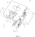
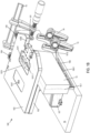
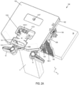
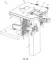
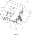
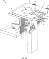
- the tenoning guide 1012.1 can be used as a template for the guide bushing of the router to begin cutting the tenon with the router support plate 103 in a first position relative to the base plate 102 ( see Figs. 2A and 2B ).
- the router support plate lever 104 is engaged to move the router support plate 103 from the first position (shown in Figs. 2A and 2B ) to the second position (shown in Figs. 3A and 3B ).
- the guide bushing of the router uses a second tenon guide surface (e.g ., the rear surface 1032 of the opening 1031) to cut the remainder of the tenon.
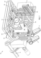
- the mortise and tenon jig system 100 includes a front mount 106, a left side mount 107, and/or a right side mount 108.
- the front mount 106 is attached to a front edge of the base plate 102.
- the left side mount 107 and right side mount 108 are each attached to a lower surface of the base plate 102 and to a rear surface of the front mount 106.
- the left side mount 107 and/or the right side mount 108 may be attached to a platform 16 as shown in Figs. 1A-3B (or may be directly attached to a table or workbench).
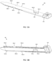
- the router support plate 103 may include at least one recess 1034 for interfacing with the guide 101 ( see Figs. 4 and 5A ).
- the router support plate 103 may include a left front recess 1034.1, a right front recess 1034.2, a left rear recess 1034.3, and a right rear recess 1034.4.
- the recesses 1034.1-1034.4 each have an approximately rectangular cross section and extend through an entire thickness of the router support plate 103.
- the router support plate 103 may also include a front central recess 1034.5 and a rear central recess 1034.6.
- the first protrusion 1013.1 of the guide 101 engages the right rear recess 1034.4 of the router support plate 103
- the second protrusion 1013.2 of the guide 101 engages the left rear recess 1034.3 of the router support plate 103
- the third protrusion 1013.3 of the guide 101 engages the right front recess 1034.2 of the router support plate 103
- the fourth protrusion 1013.4 of the guide 101 engages the left front recess 1034.1 of the router support plate 103.
- the router support plate 103 and the guide 101 may include any number, shape, combination, and arrangement of recesses/protrusions and/or any other appropriate object.
- the guide attachment portion 105 slides along the length of channel 1038 (typically by moving handle 1051) such that the proximal end 1052.1 of the slot 1052 contacts or is located adjacent to pin 1038.1.
- the distal tongues 1053.1 and 1053.3 of the guide attachment portion 105 engage the protrusions 1013 of the guide 101 extending through left front recess 1034.1 and left rear recess 1034.3 of the router support plate 103.
- proximal tongues 1053.2 and 1053.4 of the guide attachment portion 105 engage the protrusions 1013 of the guide 101 extending through right front recess 1034.2 and right rear recess 1034.4 of the router support plate 103.
- first longitudinal member 1043.1 interfaces with the tapered surface of the inside rib 1036.1 and the second longitudinal member 1043.2 interfaces with the tapered surface of the outside rib 1036.3.
- the inner surfaces of the longitudinal members 1043.1 and 1043.2 of the router support plate lever 104 engage the outer tapered surfaces of the protrusion 1024 of the base plate 102 ( see Fig. 9A ).
Landscapes
- Life Sciences & Earth Sciences (AREA)
- Engineering & Computer Science (AREA)
- Mechanical Engineering (AREA)
- Wood Science & Technology (AREA)
- Forests & Forestry (AREA)
- Milling, Drilling, And Turning Of Wood (AREA)
Claims (20)
- Verzapfungsvorrichtung (100), umfassend:eine Grundplatte (102);eine Fräserstützplatte (103), die an einer oberen Oberfläche der Grundplatte angebracht ist, die Fräserstützplatte umfassend eine Öffnung (1031); undeine Führung (101, 101b, 101c), die an der Fräserstützplatte angebracht ist, wobei:die Führung ein erstes Ende und ein zweites Ende umfasst;das erste Ende eine Zapfenlochführungsoberfläche (1011.1) umfasst;das zweite Ende eine Zapfenverbindungsführungsoberfläche (1012.1) umfasst und dadurch gekennzeichnet ist, dassdie Verzapfungsvorrichtung eine erste Konfiguration, wobei die Zapfenlochführungsoberfläche an der Öffnung ausgerichtet ist, und eine zweite Konfiguration umfasst, wobei die Zapfenverbindungsführungsoberfläche an der Öffnung ausgerichtet ist, wobei die Öffnung geformt ist, um alternativ das erste Ende der Führung aufzunehmen, wenn die Verzapfungsvorrichtung in der ersten Konfiguration ist, und das zweite Ende der Führung aufzunehmen, wenn die Verzapfungsvorrichtung in der zweiten Konfiguration ist.
- Verzapfungsvorrichtung (100) nach Anspruch 1, wobei:die Zapfenlochführungsoberfläche (1011.1) ein Loch umfasst, das etwa einer gewünschten Zapfenlochgröße entspricht; unddie Zapfenverbindungsführungsoberfläche (1012.1) einen Vorsprung umfasst, der etwa einer gewünschten Zapfenverbindungsgröße entspricht.
- Verzapfungsvorrichtung (100) nach Anspruch 1, wobei, in der zweiten Konfiguration, die Führung (101, 101b, 101c) von der ersten Konfiguration um etwa 180° gedreht ist.
- Verzapfungsvorrichtung (100) nach Anspruch 1, wobei die Führung (101, 101b, 101c) mindestens eines von (i) einer Vielzahl von Vorsprüngen (1013, 1013.1, 1013.2, 1013.3, 1013.4), die die Fräserstützplatte (103) in Eingriff nehmen, und (ii) einer Vielzahl von Aussparungen (1014, 1014.1, 1014.2) zum Ineingriffnehmen der Fräserstützplatte umfasst.
- Verzapfungsvorrichtung (100) nach Anspruch 1, wobei die Fräserstützplatte (103) an der Grundplatte (102) verschiebbar angebracht ist.
- Verzapfungsvorrichtung (100) nach Anspruch 5, wobei:die Fräserstützplatte (103) eine erste Position und eine zweite Position relativ zu der Grundplatte (102) umfasst; unddie Fräserstützplatte eine Achse zwischen der ersten und der zweiten Position entlanggleitet.
- Verzapfungsvorrichtung (100) nach Anspruch 6, wobei:in der ersten Position ein Abschnitt der Führung (101, 101b, 101c) etwa an dem Werkstück (10) ausgerichtet ist; undin der zweiten Position eine Kante der Öffnung (1031) etwa an dem Werkstück ausgerichtet ist.
- Verzapfungsvorrichtung (100) nach Anspruch 1, ferner umfassend eine vordere Halterung (106), die an einer Vorderkante der Grundplatte (102) angebracht ist.
- Verzapfungsvorrichtung (100) nach Anspruch 1, wobei:die Zapfenlochführungsoberfläche (1011.1) ein Loch umfasst, das etwa einer gewünschten Zapfenlochgröße entspricht;die Zapfenverbindungsführungsoberfläche (1012.1) einen Vorsprung umfasst, der etwa einer gewünschten Zapfenverbindungsgröße entspricht; unddie Führung (101, 101b, 101c) durch eine zweite Führung austauschbar ist, die ein Loch mit anderer Größe und einen Vorsprung mit anderer Größe umfasst.
- Verfahren zum Schneiden einer Holzverbindung, umfassend:
Befestigen eines ersten Werkstücks (10) an einer Vorrichtung (100), die Vorrichtung umfassend:eine Grundplatte;eine Fräserstützplatte (103), die an einer oberen Oberfläche der Grundplatte (102) angebracht ist, die Fräserstützplatte umfassend eine Öffnung (1031); undeine Führung (101, 101b, 101c), die an der Fräserstützplatte angebracht ist, wobei:die Führung ein erstes Ende und ein zweites Ende umfasst; unddie Vorrichtung eine erste Konfiguration, wobei das erste Ende der Führung etwa an der Öffnung ausgerichtet ist, und eine zweite Konfiguration umfasst, wobei das zweite Ende der Führung etwa an der Öffnung ausgerichtet ist, wobei die Öffnung geformt ist, um alternativ das erste Ende der Führung aufzunehmen, wenn die Verzapfungsvorrichtung in der ersten Konfiguration ist, und das zweite Ende der Führung aufzunehmen, wenn die Verzapfungsvorrichtung in der zweiten Konfiguration ist;Schneiden eines Zapfenlochs in das erste Werkstück mit der Vorrichtung in der ersten Konfiguration;Entfernen der Führung von der Fräserstützplatte;Anbringen der Führung an der Fräserstützplatte in der zweiten Konfiguration;Befestigen eines zweiten Werkstücks (11) an der Vorrichtung; undSchneiden von Abfallmaterial des zweiten Werkstücks, um mit der Vorrichtung in der zweiten Konfiguration mindestens einen Abschnitt einer Zapfenverbindung auszubilden. - Verfahren nach Anspruch 10, wobei das Schneiden des Zapfenlochs in das erste Werkstück (10) ein Bewegen einer Handfräse umfasst, die einer Schablone basierend auf einem Loch in dem ersten Ende der Führung (101, 101b, 101c) folgt.
- Verfahren nach Anspruch 10, wobei das Schneiden von Abfallmaterial des zweiten Werkstücks (11), um mindestens einen Abschnitt einer Zapfenverbindung auszubilden, das Bewegen einer Handfräse umfasst, die einer Schablone basierend auf einem Vorsprung an dem zweiten Ende der Führung (101, 101b, 101c) folgt.
- Verfahren nach Anspruch 10, wobei, nach dem Entfernen der Führung (101, 101b, 101c) von der Fräserstützplatte (103) und vor dem Anbringen der Führung an der Fräserstützplatte in der zweiten Konfiguration, das Verfahren ferner ein Drehen der Führung um etwa 180° umfasst.
- Verfahren nach Anspruch 10, ferner umfassend:Einstellen einer Stelle der Fräserstützplatte (103) relativ zu der Grundplatte (102) entlang einer Achse, um die Führung (101, 101b, 101c) an eine gewünschte Stelle von mindestens einem von dem ersten Werkstück (10) und dem zweiten Werkstück (11) auszurichten; undBefestigen der Fräserstützplatte relativ zu der Grundplatte.
- Verfahren nach Anspruch 10, wobei:die Fräserstützplatte (103) eine erste Position und eine zweite Position relativ zu der Grundplatte (102) umfasst;nach dem Schneiden von Abfallmaterial des zweiten Werkstücks (11), um mit der Vorrichtung (100) in der zweiten Konfiguration mindestens einen Abschnitt einer Zapfenverbindung auszubilden, das Verfahren ferner das Verschieben der Fräserstützplatte relativ zu der Grundplatte von der ersten Position in die zweite Position entlang einer Achse umfasst; undwenn die Fräserstützplatte in der zweiten Position ist, Schneiden eines Rests des Abfallmaterials des zweiten Werkstücks, um die Zapfenverbindung auszubilden.
- Verfahren zum Schneiden einer Holzverbindung unter Verwendung der Verzapfungsvorrichtung (100) nach den Ansprüchen 1 bis 9, das Verfahren umfassend:Befestigen eines Werkstücks (10) an der Grundplatte (102), die in der Vorrichtung enthalten ist;Bewegen der Fräserstützplatte (103), die in der Vorrichtung enthalten ist, relativ zu der Grundplatte entlang einer ersten Achse, um die Fräserstütze relativ zu dem Werkstück auszurichten;Befestigen einer Zapfenverbindungsführung in der Öffnung (1031) der Fräserstützplatte, wobei die Öffnung geformt ist, um die Zapfenverbindungsführung aufzunehmen, die Zapfenverbindungsführung (1012.1) umfassend eine erste Zapfenverbindungsführungsoberfläche und die Öffnung umfassend eine zweite Zapfenverbindungsführungsoberfläche (1032);wenn die erste Zapfenverbindungsführungsoberfläche an einer vorgesehenen Stelle für einen ersten Abschnitt einer Zapfenverbindung ausgerichtet ist, Verwenden eines Fräsers, um den ersten Abschnitt der Zapfenverbindung in dem Werkstück auszubilden, während der Fräser auf der Fräserstützplatte gestützt wird und eine Bewegung des Fräsers unter Verwendung der ersten Zapfenverbindungsführungsoberfläche geführt wird;Bewegen der Fräserstützplatte entlang der ersten Achse, um die zweite Zapfenverbindungsführungsoberfläche an einer vorgesehenen Stelle für einen zweiten Abschnitt der Zapfenverbindung auszurichten; undwenn die zweite Zapfenverbindungsführungsoberfläche an der vorgesehenen Stelle für den zweiten Abschnitt der Zapfenverbindung ausgerichtet ist, Verwenden des Fräsers, um den zweiten Abschnitt der Zapfenverbindung in dem Werkstück auszubilden, während der Fräser auf der Fräserstützplatte gestützt wird und die Bewegung des Fräsers unter Verwendung der zweiten Zapfenverbindungsführungsoberfläche geführt wird.
- Verfahren nach Anspruch 16, ferner umfassend:Befestigen eines zweiten Werkstücks (11) an der Vorrichtung (100);Befestigen einer Zapfenlochführung (1011.1) in der Öffnung (1031) der Fräserstützplatte (103), die Zapfenlochführung umfassend eine Zapfenlochführungsoberfläche; undwenn die Zapfenlochführungsoberfläche an einer vorgesehenen Stelle für ein Zapfenloch ausgerichtet ist, Verwenden des Fräsers, um das Zapfenloch in dem zweiten Werkstück auszubilden, während der Fräser auf der Fräserstütze gestützt wird und die Bewegung des Fräsers unter Verwendung der Zapfenlochführungsoberfläche geführt wird.
- Verfahren nach Anspruch 17, wobei die Zapfenverbindungsführung (1012.1) an einem ersten Ende (1012) eines Führungsabschnitts (101, 101b, 101c) ist und die Zapfenlochführung (1011.1) an einem zweiten Ende (1011) des Führungsabschnitts ist.
- Verfahren nach Anspruch 16, ferner umfassend das Ineingriffnehmen eines Plattenbefestigungshebels (109), um die Fräserstützplatte (103) relativ zu der Grundplatte (102) festzuhalten.
- Verfahren nach Anspruch 16, wobei das Bewegen der Fräserstützplatte (103) entlang der ersten Achse zwischen (i) der vorgesehenen Stelle für den ersten Abschnitt der Zapfenverbindung und (ii) der vorgesehenen Stelle für den zweiten Abschnitt der Zapfenverbindung das Bewegen eines Fräserstützplattenhebels (104) umfasst.
Applications Claiming Priority (2)
| Application Number | Priority Date | Filing Date | Title |
|---|---|---|---|
| US201762516306P | 2017-06-07 | 2017-06-07 | |
| PCT/IB2018/054127 WO2018225013A1 (en) | 2017-06-07 | 2018-06-07 | Mortise and tenon jig |
Publications (4)
| Publication Number | Publication Date |
|---|---|
| EP3634702A1 EP3634702A1 (de) | 2020-04-15 |
| EP3634702A4 EP3634702A4 (de) | 2021-03-10 |
| EP3634702C0 EP3634702C0 (de) | 2024-07-10 |
| EP3634702B1 true EP3634702B1 (de) | 2024-07-10 |
Family
ID=64562898
Family Applications (1)
| Application Number | Title | Priority Date | Filing Date |
|---|---|---|---|
| EP18814193.1A Active EP3634702B1 (de) | 2017-06-07 | 2018-06-07 | Zapfenloch- und zapfenschneidvorrichtung |
Country Status (5)
| Country | Link |
|---|---|
| US (1) | US10363643B2 (de) |
| EP (1) | EP3634702B1 (de) |
| AU (1) | AU2018279310B2 (de) |
| CA (1) | CA3066552A1 (de) |
| WO (1) | WO2018225013A1 (de) |
Families Citing this family (7)
| Publication number | Priority date | Publication date | Assignee | Title |
|---|---|---|---|---|
| AU2018279310B2 (en) | 2017-06-07 | 2024-05-23 | Lee Valley Tools Ltd. | Mortise and tenon jig |
| US12350775B2 (en) * | 2018-01-26 | 2025-07-08 | Bam Ip Holding Llc | Multi-joining system |
| US11351644B2 (en) | 2019-11-18 | 2022-06-07 | Donald Browning | Mortise cutting jig and router guidance system for wood working |
| US11780111B1 (en) | 2019-11-20 | 2023-10-10 | Luke Eckes | Tool and system for forming multiple woodworking joints |
| US12539642B1 (en) | 2019-11-20 | 2026-02-03 | Luke Eckes | Tool and system for forming multiple woodworking joints |
| USD1003141S1 (en) * | 2022-05-24 | 2023-10-31 | Super Power Tools Co., Ltd. | Tenon jig |
| KR102575556B1 (ko) * | 2023-05-24 | 2023-09-07 | 서정우 | 결구홈 절단 가이드 장치 |
Family Cites Families (12)
| Publication number | Priority date | Publication date | Assignee | Title |
|---|---|---|---|---|
| US4479523A (en) | 1982-09-30 | 1984-10-30 | Dale Peterson | Mortise and tenon jig |
| US4595040A (en) | 1985-10-10 | 1986-06-17 | Glismann Rudy L | Mortise and tenon jig |
| US4787432A (en) | 1988-06-15 | 1988-11-29 | Williams James D | Apparatus and method for producing mortise and tenon joints |
| US5123463A (en) * | 1991-04-24 | 1992-06-23 | Grisley Kenneth M | Mortise and tenon jig for a router |
| US5285832A (en) * | 1992-09-03 | 1994-02-15 | Leichtung, Inc. | Device for mortise, tenon and dovetail joinery |
| US5762115A (en) * | 1997-02-25 | 1998-06-09 | Shouse; Gary A. | Door template for use with a drill and a router |
| US5862848A (en) * | 1997-07-23 | 1999-01-26 | Beall; Jerrold R. | Hinge mortising fixture |
| US6076575A (en) * | 1998-03-03 | 2000-06-20 | Harkness; Richard C. | Apparatus for forming dovetail, box and related joints |
| US6112783A (en) * | 1998-12-09 | 2000-09-05 | Newman; Roger R. | Router guide and clamping apparatus |
| US8016005B1 (en) | 2010-03-10 | 2011-09-13 | General Tools & Instruments Company Llc | Combination mortise and tenon jig |
| US8534329B2 (en) * | 2010-12-02 | 2013-09-17 | Leigh Industries, Ltd. | Joint making jig |
| AU2018279310B2 (en) | 2017-06-07 | 2024-05-23 | Lee Valley Tools Ltd. | Mortise and tenon jig |
-
2018
- 2018-06-07 AU AU2018279310A patent/AU2018279310B2/en active Active
- 2018-06-07 WO PCT/IB2018/054127 patent/WO2018225013A1/en not_active Ceased
- 2018-06-07 EP EP18814193.1A patent/EP3634702B1/de active Active
- 2018-06-07 US US16/002,923 patent/US10363643B2/en active Active
- 2018-06-07 CA CA3066552A patent/CA3066552A1/en active Pending
Also Published As
| Publication number | Publication date |
|---|---|
| AU2018279310B2 (en) | 2024-05-23 |
| EP3634702A1 (de) | 2020-04-15 |
| US10363643B2 (en) | 2019-07-30 |
| WO2018225013A1 (en) | 2018-12-13 |
| AU2018279310A1 (en) | 2020-01-02 |
| EP3634702C0 (de) | 2024-07-10 |
| US20180354086A1 (en) | 2018-12-13 |
| EP3634702A4 (de) | 2021-03-10 |
| CA3066552A1 (en) | 2018-12-13 |
Similar Documents
| Publication | Publication Date | Title |
|---|---|---|
| AU2018279310B2 (en) | Mortise and tenon jig | |
| US4630656A (en) | Router attachment | |
| EP1375060B1 (de) | Führungsschiene für Handgerät | |
| US7857020B2 (en) | Jig apparatus | |
| US7434604B2 (en) | Jig apparatus | |
| US5289861A (en) | Multi-purpose quick-change work surface platform for use with power tools | |
| CN1727140B (zh) | 夹具装置 | |
| EP3022000B1 (de) | Multifunktionnelle führung eines schneidswerkeuges. | |
| US20030233926A1 (en) | Multi-function woodworking system | |
| EP3703912B1 (de) | Stützzusatzeinrichtung für eine werkstückauflageeinrichtung | |
| CA2755601A1 (en) | Universal fence assemblies for power tool tables having multi-position stop assemblies | |
| US20030233925A1 (en) | Multi-function woodworking adapter | |
| US8096219B2 (en) | Apparatus for conveying a workpiece to make a straight-line cut | |
| US20210178627A1 (en) | Power tool guide with positive alignment | |
| US11780111B1 (en) | Tool and system for forming multiple woodworking joints | |
| US11628588B2 (en) | Adjustable woodworking squaring jig | |
| EP4417347A1 (de) | Zapfenlochlehre | |
| US7195043B1 (en) | Router guide | |
| US20220040879A1 (en) | Table saw with a rip fence locking device | |
| EP2117770B1 (de) | Aufspannvorrichtung | |
| US20140331839A1 (en) | Precision rapid dado tool | |
| DE102010029797A1 (de) | Handwerkzeugführungsvorrichtung | |
| JP2003112303A (ja) | 木工用道具三点セット |
Legal Events
| Date | Code | Title | Description |
|---|---|---|---|
| STAA | Information on the status of an ep patent application or granted ep patent |
Free format text: STATUS: THE INTERNATIONAL PUBLICATION HAS BEEN MADE |
|
| PUAI | Public reference made under article 153(3) epc to a published international application that has entered the european phase |
Free format text: ORIGINAL CODE: 0009012 |
|
| STAA | Information on the status of an ep patent application or granted ep patent |
Free format text: STATUS: REQUEST FOR EXAMINATION WAS MADE |
|
| 17P | Request for examination filed |
Effective date: 20191205 |
|
| AK | Designated contracting states |
Kind code of ref document: A1 Designated state(s): AL AT BE BG CH CY CZ DE DK EE ES FI FR GB GR HR HU IE IS IT LI LT LU LV MC MK MT NL NO PL PT RO RS SE SI SK SM TR |
|
| AX | Request for extension of the european patent |
Extension state: BA ME |
|
| DAV | Request for validation of the european patent (deleted) | ||
| DAX | Request for extension of the european patent (deleted) | ||
| A4 | Supplementary search report drawn up and despatched |
Effective date: 20210208 |
|
| RIC1 | Information provided on ipc code assigned before grant |
Ipc: B27C 5/10 20060101AFI20210202BHEP Ipc: B27F 1/08 20060101ALI20210202BHEP |
|
| STAA | Information on the status of an ep patent application or granted ep patent |
Free format text: STATUS: EXAMINATION IS IN PROGRESS |
|
| 17Q | First examination report despatched |
Effective date: 20221019 |
|
| GRAP | Despatch of communication of intention to grant a patent |
Free format text: ORIGINAL CODE: EPIDOSNIGR1 |
|
| RAP1 | Party data changed (applicant data changed or rights of an application transferred) |
Owner name: LEE VALLEY TOOLS LTD. |
|
| STAA | Information on the status of an ep patent application or granted ep patent |
Free format text: STATUS: GRANT OF PATENT IS INTENDED |
|
| INTG | Intention to grant announced |
Effective date: 20240118 |
|
| GRAS | Grant fee paid |
Free format text: ORIGINAL CODE: EPIDOSNIGR3 |
|
| GRAA | (expected) grant |
Free format text: ORIGINAL CODE: 0009210 |
|
| STAA | Information on the status of an ep patent application or granted ep patent |
Free format text: STATUS: THE PATENT HAS BEEN GRANTED |
|
| AK | Designated contracting states |
Kind code of ref document: B1 Designated state(s): AL AT BE BG CH CY CZ DE DK EE ES FI FR GB GR HR HU IE IS IT LI LT LU LV MC MK MT NL NO PL PT RO RS SE SI SK SM TR |
|
| REG | Reference to a national code |
Ref country code: CH Ref legal event code: EP |
|
| REG | Reference to a national code |
Ref country code: DE Ref legal event code: R096 Ref document number: 602018071644 Country of ref document: DE |
|
| U01 | Request for unitary effect filed |
Effective date: 20240717 |
|
| U07 | Unitary effect registered |
Designated state(s): AT BE BG DE DK EE FI FR IT LT LU LV MT NL PT SE SI Effective date: 20240729 |
|
| PG25 | Lapsed in a contracting state [announced via postgrant information from national office to epo] |
Ref country code: NO Free format text: LAPSE BECAUSE OF FAILURE TO SUBMIT A TRANSLATION OF THE DESCRIPTION OR TO PAY THE FEE WITHIN THE PRESCRIBED TIME-LIMIT Effective date: 20241010 |
|
| PG25 | Lapsed in a contracting state [announced via postgrant information from national office to epo] |
Ref country code: GR Free format text: LAPSE BECAUSE OF FAILURE TO SUBMIT A TRANSLATION OF THE DESCRIPTION OR TO PAY THE FEE WITHIN THE PRESCRIBED TIME-LIMIT Effective date: 20241011 Ref country code: PL Free format text: LAPSE BECAUSE OF FAILURE TO SUBMIT A TRANSLATION OF THE DESCRIPTION OR TO PAY THE FEE WITHIN THE PRESCRIBED TIME-LIMIT Effective date: 20240710 |
|
| PG25 | Lapsed in a contracting state [announced via postgrant information from national office to epo] |
Ref country code: IS Free format text: LAPSE BECAUSE OF FAILURE TO SUBMIT A TRANSLATION OF THE DESCRIPTION OR TO PAY THE FEE WITHIN THE PRESCRIBED TIME-LIMIT Effective date: 20241110 |
|
| PG25 | Lapsed in a contracting state [announced via postgrant information from national office to epo] |
Ref country code: HR Free format text: LAPSE BECAUSE OF FAILURE TO SUBMIT A TRANSLATION OF THE DESCRIPTION OR TO PAY THE FEE WITHIN THE PRESCRIBED TIME-LIMIT Effective date: 20240710 |
|
| PG25 | Lapsed in a contracting state [announced via postgrant information from national office to epo] |
Ref country code: ES Free format text: LAPSE BECAUSE OF FAILURE TO SUBMIT A TRANSLATION OF THE DESCRIPTION OR TO PAY THE FEE WITHIN THE PRESCRIBED TIME-LIMIT Effective date: 20240710 Ref country code: RS Free format text: LAPSE BECAUSE OF FAILURE TO SUBMIT A TRANSLATION OF THE DESCRIPTION OR TO PAY THE FEE WITHIN THE PRESCRIBED TIME-LIMIT Effective date: 20241010 |
|
| PG25 | Lapsed in a contracting state [announced via postgrant information from national office to epo] |
Ref country code: RS Free format text: LAPSE BECAUSE OF FAILURE TO SUBMIT A TRANSLATION OF THE DESCRIPTION OR TO PAY THE FEE WITHIN THE PRESCRIBED TIME-LIMIT Effective date: 20241010 Ref country code: PL Free format text: LAPSE BECAUSE OF FAILURE TO SUBMIT A TRANSLATION OF THE DESCRIPTION OR TO PAY THE FEE WITHIN THE PRESCRIBED TIME-LIMIT Effective date: 20240710 Ref country code: NO Free format text: LAPSE BECAUSE OF FAILURE TO SUBMIT A TRANSLATION OF THE DESCRIPTION OR TO PAY THE FEE WITHIN THE PRESCRIBED TIME-LIMIT Effective date: 20241010 Ref country code: IS Free format text: LAPSE BECAUSE OF FAILURE TO SUBMIT A TRANSLATION OF THE DESCRIPTION OR TO PAY THE FEE WITHIN THE PRESCRIBED TIME-LIMIT Effective date: 20241110 Ref country code: HR Free format text: LAPSE BECAUSE OF FAILURE TO SUBMIT A TRANSLATION OF THE DESCRIPTION OR TO PAY THE FEE WITHIN THE PRESCRIBED TIME-LIMIT Effective date: 20240710 Ref country code: GR Free format text: LAPSE BECAUSE OF FAILURE TO SUBMIT A TRANSLATION OF THE DESCRIPTION OR TO PAY THE FEE WITHIN THE PRESCRIBED TIME-LIMIT Effective date: 20241011 Ref country code: ES Free format text: LAPSE BECAUSE OF FAILURE TO SUBMIT A TRANSLATION OF THE DESCRIPTION OR TO PAY THE FEE WITHIN THE PRESCRIBED TIME-LIMIT Effective date: 20240710 |
|
| PG25 | Lapsed in a contracting state [announced via postgrant information from national office to epo] |
Ref country code: SM Free format text: LAPSE BECAUSE OF FAILURE TO SUBMIT A TRANSLATION OF THE DESCRIPTION OR TO PAY THE FEE WITHIN THE PRESCRIBED TIME-LIMIT Effective date: 20240710 |
|
| PG25 | Lapsed in a contracting state [announced via postgrant information from national office to epo] |
Ref country code: CZ Free format text: LAPSE BECAUSE OF FAILURE TO SUBMIT A TRANSLATION OF THE DESCRIPTION OR TO PAY THE FEE WITHIN THE PRESCRIBED TIME-LIMIT Effective date: 20240710 |
|
| PG25 | Lapsed in a contracting state [announced via postgrant information from national office to epo] |
Ref country code: SK Free format text: LAPSE BECAUSE OF FAILURE TO SUBMIT A TRANSLATION OF THE DESCRIPTION OR TO PAY THE FEE WITHIN THE PRESCRIBED TIME-LIMIT Effective date: 20240710 |
|
| PLBE | No opposition filed within time limit |
Free format text: ORIGINAL CODE: 0009261 |
|
| STAA | Information on the status of an ep patent application or granted ep patent |
Free format text: STATUS: NO OPPOSITION FILED WITHIN TIME LIMIT |
|
| 26N | No opposition filed |
Effective date: 20250411 |
|
| U20 | Renewal fee for the european patent with unitary effect paid |
Year of fee payment: 8 Effective date: 20250602 |
|
| REG | Reference to a national code |
Ref country code: CH Ref legal event code: H13 Free format text: ST27 STATUS EVENT CODE: U-0-0-H10-H13 (AS PROVIDED BY THE NATIONAL OFFICE) Effective date: 20260127 |
|
| PG25 | Lapsed in a contracting state [announced via postgrant information from national office to epo] |
Ref country code: MC Free format text: LAPSE BECAUSE OF FAILURE TO SUBMIT A TRANSLATION OF THE DESCRIPTION OR TO PAY THE FEE WITHIN THE PRESCRIBED TIME-LIMIT Effective date: 20240710 |
|
| GBPC | Gb: european patent ceased through non-payment of renewal fee |
Effective date: 20250607 |
|
| PG25 | Lapsed in a contracting state [announced via postgrant information from national office to epo] |
Ref country code: GB Free format text: LAPSE BECAUSE OF NON-PAYMENT OF DUE FEES Effective date: 20250607 |
|
| PG25 | Lapsed in a contracting state [announced via postgrant information from national office to epo] |
Ref country code: IE Free format text: LAPSE BECAUSE OF NON-PAYMENT OF DUE FEES Effective date: 20250607 |
|
| PG25 | Lapsed in a contracting state [announced via postgrant information from national office to epo] |
Ref country code: RO Free format text: LAPSE BECAUSE OF FAILURE TO SUBMIT A TRANSLATION OF THE DESCRIPTION OR TO PAY THE FEE WITHIN THE PRESCRIBED TIME-LIMIT Effective date: 20240710 |
|
| PG25 | Lapsed in a contracting state [announced via postgrant information from national office to epo] |
Ref country code: CH Free format text: LAPSE BECAUSE OF NON-PAYMENT OF DUE FEES Effective date: 20250630 |