EP3634730B1 - Verfahren zum herstellen eines windenergieanlagen-rotorblattes - Google Patents
Verfahren zum herstellen eines windenergieanlagen-rotorblattes Download PDFInfo
- Publication number
- EP3634730B1 EP3634730B1 EP18731035.4A EP18731035A EP3634730B1 EP 3634730 B1 EP3634730 B1 EP 3634730B1 EP 18731035 A EP18731035 A EP 18731035A EP 3634730 B1 EP3634730 B1 EP 3634730B1
- Authority
- EP
- European Patent Office
- Prior art keywords
- spar
- rotor blade
- wind turbine
- cap
- mold
- Prior art date
- Legal status (The legal status is an assumption and is not a legal conclusion. Google has not performed a legal analysis and makes no representation as to the accuracy of the status listed.)
- Active
Links
Images


Classifications
-
- B—PERFORMING OPERATIONS; TRANSPORTING
- B29—WORKING OF PLASTICS; WORKING OF SUBSTANCES IN A PLASTIC STATE IN GENERAL
- B29D—PRODUCING PARTICULAR ARTICLES FROM PLASTICS OR FROM SUBSTANCES IN A PLASTIC STATE
- B29D99/00—Subject matter not provided for in other groups of this subclass
- B29D99/0025—Producing blades or the like, e.g. blades for turbines, propellers, or wings
- B29D99/0028—Producing blades or the like, e.g. blades for turbines, propellers, or wings hollow blades
-
- B—PERFORMING OPERATIONS; TRANSPORTING
- B29—WORKING OF PLASTICS; WORKING OF SUBSTANCES IN A PLASTIC STATE IN GENERAL
- B29C—SHAPING OR JOINING OF PLASTICS; SHAPING OF MATERIAL IN A PLASTIC STATE, NOT OTHERWISE PROVIDED FOR; AFTER-TREATMENT OF THE SHAPED PRODUCTS, e.g. REPAIRING
- B29C65/00—Joining or sealing of preformed parts, e.g. welding of plastics materials; Apparatus therefor
- B29C65/56—Joining or sealing of preformed parts, e.g. welding of plastics materials; Apparatus therefor using mechanical means or mechanical connections, e.g. form-fits
-
- B—PERFORMING OPERATIONS; TRANSPORTING
- B29—WORKING OF PLASTICS; WORKING OF SUBSTANCES IN A PLASTIC STATE IN GENERAL
- B29C—SHAPING OR JOINING OF PLASTICS; SHAPING OF MATERIAL IN A PLASTIC STATE, NOT OTHERWISE PROVIDED FOR; AFTER-TREATMENT OF THE SHAPED PRODUCTS, e.g. REPAIRING
- B29C70/00—Shaping composites, i.e. plastics material comprising reinforcements, fillers or preformed parts, e.g. inserts
- B29C70/04—Shaping composites, i.e. plastics material comprising reinforcements, fillers or preformed parts, e.g. inserts comprising reinforcements only, e.g. self-reinforcing plastics
- B29C70/28—Shaping operations therefor
- B29C70/30—Shaping by lay-up, i.e. applying fibres, tape or broadsheet on a mould, former or core; Shaping by spray-up, i.e. spraying of fibres on a mould, former or core
- B29C70/302—Details of the edges of fibre composites, e.g. edge finishing or means to avoid delamination
-
- B—PERFORMING OPERATIONS; TRANSPORTING
- B29—WORKING OF PLASTICS; WORKING OF SUBSTANCES IN A PLASTIC STATE IN GENERAL
- B29C—SHAPING OR JOINING OF PLASTICS; SHAPING OF MATERIAL IN A PLASTIC STATE, NOT OTHERWISE PROVIDED FOR; AFTER-TREATMENT OF THE SHAPED PRODUCTS, e.g. REPAIRING
- B29C70/00—Shaping composites, i.e. plastics material comprising reinforcements, fillers or preformed parts, e.g. inserts
- B29C70/04—Shaping composites, i.e. plastics material comprising reinforcements, fillers or preformed parts, e.g. inserts comprising reinforcements only, e.g. self-reinforcing plastics
- B29C70/28—Shaping operations therefor
- B29C70/30—Shaping by lay-up, i.e. applying fibres, tape or broadsheet on a mould, former or core; Shaping by spray-up, i.e. spraying of fibres on a mould, former or core
- B29C70/304—In-plane lamination by juxtaposing or interleaving of plies, e.g. scarf joining
-
- B—PERFORMING OPERATIONS; TRANSPORTING
- B29—WORKING OF PLASTICS; WORKING OF SUBSTANCES IN A PLASTIC STATE IN GENERAL
- B29C—SHAPING OR JOINING OF PLASTICS; SHAPING OF MATERIAL IN A PLASTIC STATE, NOT OTHERWISE PROVIDED FOR; AFTER-TREATMENT OF THE SHAPED PRODUCTS, e.g. REPAIRING
- B29C70/00—Shaping composites, i.e. plastics material comprising reinforcements, fillers or preformed parts, e.g. inserts
- B29C70/04—Shaping composites, i.e. plastics material comprising reinforcements, fillers or preformed parts, e.g. inserts comprising reinforcements only, e.g. self-reinforcing plastics
- B29C70/28—Shaping operations therefor
- B29C70/30—Shaping by lay-up, i.e. applying fibres, tape or broadsheet on a mould, former or core; Shaping by spray-up, i.e. spraying of fibres on a mould, former or core
- B29C70/34—Shaping by lay-up, i.e. applying fibres, tape or broadsheet on a mould, former or core; Shaping by spray-up, i.e. spraying of fibres on a mould, former or core and shaping or impregnating by compression, i.e. combined with compressing after the lay-up operation
- B29C70/342—Shaping by lay-up, i.e. applying fibres, tape or broadsheet on a mould, former or core; Shaping by spray-up, i.e. spraying of fibres on a mould, former or core and shaping or impregnating by compression, i.e. combined with compressing after the lay-up operation using isostatic pressure
-
- B—PERFORMING OPERATIONS; TRANSPORTING
- B29—WORKING OF PLASTICS; WORKING OF SUBSTANCES IN A PLASTIC STATE IN GENERAL
- B29C—SHAPING OR JOINING OF PLASTICS; SHAPING OF MATERIAL IN A PLASTIC STATE, NOT OTHERWISE PROVIDED FOR; AFTER-TREATMENT OF THE SHAPED PRODUCTS, e.g. REPAIRING
- B29C70/00—Shaping composites, i.e. plastics material comprising reinforcements, fillers or preformed parts, e.g. inserts
- B29C70/04—Shaping composites, i.e. plastics material comprising reinforcements, fillers or preformed parts, e.g. inserts comprising reinforcements only, e.g. self-reinforcing plastics
- B29C70/28—Shaping operations therefor
- B29C70/54—Component parts, details or accessories; Auxiliary operations, e.g. feeding or storage of prepregs or SMC after impregnation or during ageing
- B29C70/545—Perforating, cutting or machining during or after moulding
-
- B—PERFORMING OPERATIONS; TRANSPORTING
- B29—WORKING OF PLASTICS; WORKING OF SUBSTANCES IN A PLASTIC STATE IN GENERAL
- B29C—SHAPING OR JOINING OF PLASTICS; SHAPING OF MATERIAL IN A PLASTIC STATE, NOT OTHERWISE PROVIDED FOR; AFTER-TREATMENT OF THE SHAPED PRODUCTS, e.g. REPAIRING
- B29C70/00—Shaping composites, i.e. plastics material comprising reinforcements, fillers or preformed parts, e.g. inserts
- B29C70/68—Shaping composites, i.e. plastics material comprising reinforcements, fillers or preformed parts, e.g. inserts by incorporating or moulding on preformed parts, e.g. inserts or layers, e.g. foam blocks
- B29C70/681—Component parts, details or accessories; Auxiliary operations
-
- B—PERFORMING OPERATIONS; TRANSPORTING
- B29—WORKING OF PLASTICS; WORKING OF SUBSTANCES IN A PLASTIC STATE IN GENERAL
- B29D—PRODUCING PARTICULAR ARTICLES FROM PLASTICS OR FROM SUBSTANCES IN A PLASTIC STATE
- B29D99/00—Subject matter not provided for in other groups of this subclass
- B29D99/0025—Producing blades or the like, e.g. blades for turbines, propellers, or wings
-
- F—MECHANICAL ENGINEERING; LIGHTING; HEATING; WEAPONS; BLASTING
- F03—MACHINES OR ENGINES FOR LIQUIDS; WIND, SPRING, OR WEIGHT MOTORS; PRODUCING MECHANICAL POWER OR A REACTIVE PROPULSIVE THRUST, NOT OTHERWISE PROVIDED FOR
- F03D—WIND MOTORS
- F03D1/00—Wind motors with rotation axis substantially parallel to the air flow entering the rotor
- F03D1/06—Rotors
- F03D1/065—Rotors characterised by their construction elements
- F03D1/0675—Rotors characterised by their construction elements of the blades
- F03D1/0679—Load carrying structures, e.g. beams
- F03D1/0681—Spar caps
-
- B—PERFORMING OPERATIONS; TRANSPORTING
- B29—WORKING OF PLASTICS; WORKING OF SUBSTANCES IN A PLASTIC STATE IN GENERAL
- B29C—SHAPING OR JOINING OF PLASTICS; SHAPING OF MATERIAL IN A PLASTIC STATE, NOT OTHERWISE PROVIDED FOR; AFTER-TREATMENT OF THE SHAPED PRODUCTS, e.g. REPAIRING
- B29C2793/00—Shaping techniques involving a cutting or machining operation
- B29C2793/0081—Shaping techniques involving a cutting or machining operation before shaping
-
- B—PERFORMING OPERATIONS; TRANSPORTING
- B29—WORKING OF PLASTICS; WORKING OF SUBSTANCES IN A PLASTIC STATE IN GENERAL
- B29L—INDEXING SCHEME ASSOCIATED WITH SUBCLASS B29C, RELATING TO PARTICULAR ARTICLES
- B29L2031/00—Other particular articles
- B29L2031/08—Blades for rotors, stators, fans, turbines or the like, e.g. screw propellers
- B29L2031/082—Blades, e.g. for helicopters
- B29L2031/085—Wind turbine blades
-
- Y—GENERAL TAGGING OF NEW TECHNOLOGICAL DEVELOPMENTS; GENERAL TAGGING OF CROSS-SECTIONAL TECHNOLOGIES SPANNING OVER SEVERAL SECTIONS OF THE IPC; TECHNICAL SUBJECTS COVERED BY FORMER USPC CROSS-REFERENCE ART COLLECTIONS [XRACs] AND DIGESTS
- Y02—TECHNOLOGIES OR APPLICATIONS FOR MITIGATION OR ADAPTATION AGAINST CLIMATE CHANGE
- Y02P—CLIMATE CHANGE MITIGATION TECHNOLOGIES IN THE PRODUCTION OR PROCESSING OF GOODS
- Y02P70/00—Climate change mitigation technologies in the production process for final industrial or consumer products
- Y02P70/50—Manufacturing or production processes characterised by the final manufactured product
Definitions
- Fig. 1 shows a schematic cross-section of a rotor blade of a wind turbine.
- the rotor blade typically consists of two shells, with a first shell 10 representing the suction side and a second shell 20 representing the pressure side. Furthermore, the rotor blade has a spar flange 40 on the suction side and the pressure side as well as webs 30 which connect the spar flanges 40 on the suction side and pressure side to one another.
- the spar flanges 40 are firmly connected to the material of the suction side and/or pressure side.
- the spar belt consists of a plurality of individual layers of a glass fiber or carbon fiber fabric, which are placed in a mold. A vacuum film is then placed and epoxy resin is infused through the volume limited by the mold and the vacuum film. When the resin has dried, the belt can be reused.
- the belt can then be provided on an inner side of the first or second shell (suction side or pressure side).
- the side walls of the mold can have a slight incline, so that the ends of the spar belt can also be slightly inclined.
- the individual layers of fabric should be scarfed crosswise.
- Foam wedges or foam triangles of different thicknesses can be used to achieve the scarfing.
- the straps are provided with a straight edge or end.
- a first wedge made of a softer material is provided and a second wedge made of a harder material can be provided on the first wedge so that the strap has a softer material on its outer part.
- the straps are manufactured with a rectangular cross-section.
- a cross-shaft can be simulated by foam wedges, especially at the edges.
- foam wedges especially at the edges.
- a lower layer of glass fiber can be inserted and a foam strip can be placed on the edges of the mold.
- This foam strip is then designed as a wedge, which has been negatively serrated towards the inside.
- the glass fabric can then be placed in this negative serration.
- the glass fiber fabrics, which form the main part of the spar cap, must be serrated in the transverse direction in order to provide smooth transitions between the spar cap, which is designed as a structural component, and the sandwich, which borders the upper and lower edges of the blade.
- the foam strip, which is provided on the edge of the spar cap can have a different thickness, which makes it very expensive to manufacture.
- German Patent and Trademark Office has researched the following documents: DE 10 2009 047 570 A1 , DE 10 2012 219 226 A1 , DE 10 2010 002 432 A1 , DE 103 36 461 A1 and US 2017/0 001 387 A1 .
- a foam wedge or a foam part can be used.
- This foam part can have a resin channel. Core material can then be provided.
- US 2015/314537 A1 shows a method for manufacturing a wind turbine rotor blade, wherein a mold is provided for a spar cap.
- the cap is provided with two lips and the cap is embedded in a core material.
- a method of manufacturing a wind turbine rotor blade is provided.
- a mold for a spar cap is provided.
- the mold has at least one negative cap edge.
- Glass fiber layers are laid into the mold and the negative cap edge to achieve a transverse shank at the ends of the glass fiber layers so that a spar cap with a negative shank is provided.
- the spar cap with the negative shank is installed in a core material of the rotor blade.
- the cap edge has an angle between 20° and 40°.
- the mold comprises a part having a scarf.
- the mold has at least one resin channel.
- the invention relates to the idea of providing a spar cap for a wind turbine rotor blade without foam strips at the ends of the spar cap.
- This can be achieved in particular by providing the foam wedges as part of the mold or by already integrating the wedges or foam wedges into the mold for producing the spar cap. Although this leads to a more complicated mold, it improves the manufacturing process or the manufacture of the spar cap.
- Glass fiber layers can then be sheathed in the mold according to the invention.
- the glass fiber layup layers can be sheathed up on the negative edge of the cap. This makes it possible to achieve a desired transverse sheathing.
- the mold obtained in this way can fit a machine-made sandwich foam mold, whereby the sandwich foam can be introduced under or into the negative sheathing.
- the spar cap is manufactured with a negative scarf.
- the spar cap can be manufactured from glass fiber fabric and the material of the spar cap is thus a hard material or a hardened material.
- the foam part can have a scarf and a resin channel.
- the foam part which is used to provide the resin channel can be scarfed positively so that it then matches the negative scarf of the spar cap.
- a transition between a hard and a soft material can be provided at the transition between the fabric of the spar cap and the foam part.
- a scarf joint represents an end of a part or element (e.g. the spar flange) that is bevelled at an acute angle.
- the scarf joint can reduce peel stresses, so that the strength of the connection is increased.
- spar flanges are typically manufactured in a box shape and flange edge strips are used at the spar flange transition to the core material, gaps can occur between the spar flange and the core material.
- inventive transverse seaming of the fabric provides a fixed width of the spar flange, which is stepped or seamed in the transverse direction. This makes it possible to provide a form-fitting and essentially gap-free transition between the core material, the rotor blade shell and the spar flange. This is achieved in particular by the negative seaming of the spar flange.
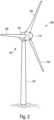
- Fig. 2 shows a schematic representation of a wind turbine according to the invention.
- the wind turbine 100 has a tower 102 and a nacelle 104 on the tower 102.
- An aerodynamic rotor 106 with three rotor blades 200 and a spinner 110 is provided on the nacelle 104.
- the aerodynamic rotor 106 is set in rotation by the wind during operation of the wind turbine and thus also rotates a rotor or runner of a generator which is directly or indirectly coupled to the aerodynamic rotor 106.
- the electrical generator is arranged in the nacelle 104 and generates electrical energy.
- the pitch angles of the rotor blades 200 can be changed by pitch motors on the rotor blade roots of the respective rotor blades 200.
- Fig. 3A to 3D show various schematic sectional views of a part of the rotor blade 200 according to the invention during the manufacture of a spar cap.
- Fig. 3B is a schematic sectional view along section A - A and in Fig. 3C a schematic sectional view along section B - B is shown.
- the method according to the invention for producing a spar cap 400 for a rotor blade 200 of a wind turbine uses a mold 300 with specially designed mold edges 310, 320.
- a leading edge 201 of the spar cap is shown.
- a core material 210 of the rotor blade 200 is shown in Fig. 3A shown.
- the mold 300 with the mold edges 310, 320 and the spar flange 400 with a first and second end 401, 402 are shown.
- the angle of a first mold edge 310 can be 35° and the angle of a second mold edge 320 can be 22°. According to one aspect of the present invention, these angles can be designed to be constant.
- a narrow belt 410 and/or a wide belt 420 may be provided.
- FIG. 3C An alternative embodiment of the mold 300 with a second mold edge 320 is provided.
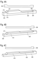
- Fig. 4A to 4C show various schematic sectional views of a spar cap according to the invention.
- the form 300 (above) and the form 300 with the spar 400 are shown.
- the design of the form 300 and the spar flange 400 according to Fig. 4A essentially corresponds to the design of the shape and the spar flange of Fig. 3B .
- the design of the shape and the spar flange according to Fig. 4B essentially corresponds to the design of the form 300 and the spar flange 400 of Fig. 3C .
- Fig. 5 shows a schematic cross section of a part of a rotor blade according to an embodiment of the invention.
- core material 210 a spar cap 400 with a first and second end 401, 402 and optionally a foam insert 500 are shown.
- the first and second ends 401, 402 of the spar cap each have a negative scarf.
- the foam insert 500 has a beveled end 510 and optionally a resin channel 520.
- the resin channel 520 can be provided on the opposite side to the end 510.
- a spar cap 400 with its two ends, each of which has a negative curvature, is provided in a core material 210 of the rotor blade.
- the flat angle of the spar cap in combination with that of the core material 210 will enable a large-area, form-fitting and gap-free transition between the spar cap and the core material of the rotor blade.
Landscapes
- Engineering & Computer Science (AREA)
- Mechanical Engineering (AREA)
- Chemical & Material Sciences (AREA)
- Composite Materials (AREA)
- Life Sciences & Earth Sciences (AREA)
- Sustainable Development (AREA)
- Sustainable Energy (AREA)
- Combustion & Propulsion (AREA)
- General Engineering & Computer Science (AREA)
- Wind Motors (AREA)
- Moulding By Coating Moulds (AREA)
Description
-
Fig. 1 zeigt einen schematischen Querschnitt eines Rotorblatts einer Windenergieanlage. Das Rotorblatt besteht typischerweise aus zwei Schalen, wobei eine erste Schale 10 die Saugseite und eine zweite Schale 20 die Druckseite darstellt. Ferner weist das Rotorblatt jeweils einen Holmgurt 40 an der Saugseite und der Druckseite sowie Stege 30 auf, welche die Holmgurte 40 an der Saugseite und Druckseite miteinander verbinden. Die Holmgurte 40 sind dabei mit dem Material der Saugseite und/oder Druckseite fest verbunden. -
DE 10 2009 047 570 A1 beschreibt einen Holmgurt einer Windenergieanlage sowie die Herstellung eines derartigen Holmgurtes. Der Holmgurt besteht aus einer Mehrzahl von Einzellagen aus einem Glasfaser- oder Kohlenfasergelege, welche in einer Form platziert werden. Anschließend wird eine Vakuumfolie platziert und Epoxidharz wird durch das das Volumen, welches durch die Form und die Vakuumfolie begrenzt ist, infundiert. Wenn das Harz getrocknet ist, dann kann der Gurt weiterverwendet werden. Der Gurt kann dann an einer Innenseite der ersten oder zweiten Schale (Saugseite oder Druckseite) vorgesehen werden. Die Seitenwände der Form können eine leichte Neigung aufweisen, so dass die Enden des Holmgurtes ebenfalls leicht geneigt sein können. - Bei der Herstellung von Holmgurten sollen die einzelnen Gelegebahnen quer geschäftet werden. Zur Erreichung der Schäftung können Schaumkeile oder Schaumdreiecke in unterschiedlichen Dicken verwendet werden.
- Typischerweise werden die Gurte mit einem geraden Rand bzw. Ende vorgesehen. Dazu wird ein erster Keil aus einem weicheren Material vorgesehen und auf dem ersten Keil kann ein zweiter Keil mit einem härteren Material vorgesehen werden, so dass der Gurt an seinem Außenbereich ein weicheres Material aufweist.
- Typischerweise werden die Gurte im Querschnitt rechteckig gefertigt. Während dieses Prozesses kann eine Querschäftung durch Schaumkeile simuliert werden, insbesondere an den Rändern kann der Schaumstoffkeil vorgesehen werden. Dies ist jedoch hinsichtlich der Transportierbarkeit der Holmgurte nachteilig, da die weichen Schaumkeile beschädigt werden können.
- Beim Herstellen des Holmgurtes kann eine untere Glasfaserlage eingelegt und an den Formrändern kann ein Schaumstoffstreifen platziert werden. Dieser Schaumstoffstreifen ist dann als Keil ausgestaltet, welcher nach innen negativ reingeschäftet worden ist. In diese negative Schäftung kann dann das Glasgelege platziert werden. Die Glasfasergelege, welche den Hauptteil des Holmgurtes ausbilden, müssen in Querrichtung geschäftet werden, um weiche Übergänge zwischen dem als strukturellen Bauteil ausgestalteten Holmgurt und dem Sandwich vorzusehen, welches an der Blattober und -unterkante angrenzt. Der Schaumstreifen, welcher am Rand des Holmgurtes vorgesehen wird, kann eine unterschiedliche Dicke aufweisen, wodurch er sehr teuer in der Herstellung ist.
- In der prioritätsbegründenden deutschen Patentanmeldung hat das Deutsche Patent- und Markenamt die folgenden Dokumente recherchiert:
DE 10 2009 047 570 A1 ,DE 10 2012 219 226 A1 ,DE 10 2010 002 432 A1 ,DE 103 36 461 A1 undUS 2017/0 001 387 A1 . - Beim Einbau des Gurtes in ein Rotorblatt einer Windenergieanlage kann ein Schaumstoffkeil bzw. ein Schaumteil verwendet. Dieses Schaumteil kann einen Harzkanal aufweisen. Anschließend kann Kernmaterial vorgesehen sein.
-
US 2015/314537 A1 zeigt ein Verfahren zum Herstellen eines Windenergieanlagen-Rotorblattes, wobei eine Form für einen Holmgurt vorgesehen wird. Der Gurt wird mit zwei Lippen vorgesehen und der Gurt ist in ein Kernmaterial eingebettet. - Es ist eine Aufgabe der vorliegenden Erfindung, ein Verfahren zur verbesserten Herstellung eines Windenergieanlagen-Rotorblattes vorzusehen. Insbesondere ist es eine Aufgabe der vorliegenden Erfindung, die Herstellung von Holmgurten für Windenergieanlagen-Rotorblätter zu verbessern.
- Diese Aufgabe wird durch ein Verfahren zum Herstellen eines Windenergieanlagen-Rotorblattes gemäß Anspruch 1 gelöst.
- Somit wird ein Verfahren zum Herstellen eines Windenergieanlagen-Rotorblattes vorgesehen. Eine Form für einen Holmgurt wird bereitgestellt. Die Form weist mindestens einen negativen Gurtrand auf. Glasfaserlagen werden in die Form und den negativen Gurtrand eingelegt, um eine Querschäftung an den Enden der Glasfaserlagen zu erreichen, so dass ein Holmgurt mit einer negativen Schäftung vorgesehen wird. Der Holmgurt mit der negativen Schäftung wird in ein Kernmaterial des Rotorblattes eingebaut. Der Gurtrand weist einen Winkel zwischen 20° und 40° auf.
- Gemäß einem Aspekt der vorliegenden Erfindung weist die Form ein Teil auf, welches eine Schäftung aufweist.
- Gemäß einem weiteren Aspekt der vorliegenden Erfindung weist die Form mindestens einen Harzkanal auf.
- Die Erfindung betrifft den Gedanken, einen Holmgurt für ein Windenergieanlagen-Rotorblatt ohne Schaumstreifen an den Enden des Holmgurtes vorzusehen. Dies kann insbesondere dadurch erreicht werden, dass die Schaumkeile als Teil der Form vorgesehen sind bzw. die Keile oder Schaumkeile in die Form zum Herstellen des Holmgurtes bereits integriert sind. Dies führt zwar zu einer komplizierteren Form, verbessert jedoch das Herstellverfahren bzw. die Herstellung des Holmgurtes. In die erfindungsgemäße Form können dann Glasfaserlagen geschäftet werden. Insbesondere können die Glasfasergelegelagen an dem negativen Gurtrand hochgeschäftet werden. Damit kann eine gewünschte Querschäftung erreicht werden. Die dabei erhaltene Abformung kann zu einer maschinell hergestellten Sandwich-Schaumform passen, wobei der Sandwich-Schaum unter bzw. in die Negativschäftung eingeführt werden kann.
- Gemäß der Erfindung wird der Holmgurt mit einer negativen Schäftung hergestellt. Der Holmgurt kann aus Glasfasergelegen hergestellt werden und das Material des Holmgurtes stellt somit ein hartes Material bzw. ein ausgehärtetes Material dar.
- Das Schaumteil kann eine Schäftung und einen Harzkanal aufweisen. Das Schaumteil, welches für das Vorsehen des Harzkanals verwendet wird, kann positiv geschäftet werden, so dass dies dann mit der negativen Schäftung des Holmgurtes zusammenpasst. Hierbei kann ein Übergang zwischen einem harten und einem weichen Material am Übergang zwischen dem Gelege des Holmgurtes und dem Schaumteil vorgesehen sein.
- Durch die erfindungsgemäße Herstellung des Holmgurtes werden keine zusätzlichen Kernmaterialstreifen zum Höhenausgleich benötigt. Die Querschäftungen der einzelnen Gelegebauteile werden beibehalten, ein spaltfreier Formschluss zum Kernmaterial der Rotorschale wird gewährleistet und das Bauteil kann besäumfrei gefertigt werden.
- Gemäß einem Aspekt der Erfindung stellt eine Schäftung ein Ende eines Teils oder Elementes (z. B. des Holmgurtes) dar, das in einem spitzen Winkel abgeschrägt ist. Durch die Schäftung können Schälspannungen reduziert werden, so dass die Festigkeit der Verbindung gesteigert wird.
- Während im Stand der Technik Holmgurte typischerweise in einer Kastenform hergestellt werden und am Holmgurtübergang zum Kernmaterial Gurtrandstreifen verwendet werden, kann es zu Spalten zwischen dem Holmgurt und dem Kernmaterial kommen. Im Gegensatz dazu wird mit der erfindungsgemäßen Querschäftung der Gelege eine fest definierte Gelegebreite des Holmgurtes vorgesehen, welcher in Querrichtung abgestuft bzw. geschäftet ist. Damit kann ein formschlüssiger und im Wesentlicher spaltfreier Übergang zwischen dem Kernmaterial, der Rotorblattschale und dem Holmgurt vorgesehen werden. Dies wird insbesondere durch die negative Schäftung des Holmgurtes erreicht.
- Weitere Ausgestaltungen der Erfindung sind Gegenstand der Unteransprüche.
- Vorteile und Ausführungsbeispiele der Erfindung werden nachstehend unter Bezugnahme auf die Zeichnung näher erläutert.
- Fig. 1
- zeigt einen schematischen Querschnitt eines Windenergieanlagen-Rotorblattes gemäß dem Stand der Technik,
- Fig. 2
- zeigt eine schematische Darstellung einer Windenergieanlage gemäß der Erfindung,
- Fig. 3A
- zeigt eine schematische Schnittansicht eines Teils eines Rotorblattes,
- Fig. 3B
- zeigt eine schematische Schnittansicht A-A von
Fig. 3A , - Fig. 3C
- zeigt eine schematische Schnittansicht B-B des Schnitts von
Fig. 3A , - Fig. 4A
- zeigt eine schematische Schnittansicht eines Holmgurtes bei seiner Herstellung,
- Fig. 4B
- zeigt eine weitere schematische Schnittansicht eines Holmgurtes bei seiner Herstellung,
- Fig. 4C
- zeigt eine weitere schematische Schnittansicht eines Holmgurtes bei seiner Herstellung, und
- Fig. 5
- zeigt einen schematischen Querschnitt eines Teils eines Rotorblattes gemäß einem Ausführungsbeispiel der Erfindung.
-
Fig. 2 zeigt eine schematische Darstellung einer Windenergieanlage gemäß der Erfindung. Die Windenergieanlage 100 weist einen Turm 102 und eine Gondel 104 auf dem Turm 102 auf. An der Gondel 104 ist ein aerodynamischer Rotor 106 mit drei Rotorblättern 200 und einem Spinner 110 vorgesehen. Der aerodynamische Rotor 106 wird im Betrieb der Windenergieanlage durch den Wind in eine Drehbewegung versetzt und dreht somit auch einen Rotor oder Läufer eines Generators, welcher direkt oder indirekt mit dem aerodynamischen Rotor 106 gekoppelt ist. Der elektrische Generator ist in der Gondel 104 angeordnet und erzeugt elektrische Energie. Die Pitchwinkel der Rotorblätter 200 können durch Pitchmotoren an den Rotorblattwurzeln der jeweiligen Rotorblätter 200 verändert werden. -
Fig. 3A bis 3D zeigen verschiedene schematische Schnittansichten eines Teils des Rotorblattes 200 gemäß der Erfindung bei der Herstellung eines Holmgurtes. InFig. 3B ist eine schematische Schnittansicht entlang des Schnitts A - A und inFig. 3C ist eine schematische Schnittansicht entlang des Schnitts B - B gezeigt. - Das erfindungsgemäße Verfahren zum Herstellen eines Holmgurtes 400 für ein Rotorblatt 200 einer Windenergieanlage verwendet eine Form 300 mit speziell ausgestalteten Formrändern 310, 320. In den
Fig. 3A bis 3C ist eine Vorderkante 201 des Holmgurtes gezeigt. Ferner ist ein Kernmaterial 210 des Rotorblattes 200 inFig. 3A gezeigt. InFig. 3B und 3C ist die Form 300 mit den Formrändern 310, 320 sowie der Holmgurt 400 mit einem ersten und zweiten Ende 401, 402 gezeigt. - Gemäß einem Aspekt der vorliegenden Erfindung kann der Winkel eines ersten Formrandes 310 35° und der Winkel eines zweiten Formrandes 320 22° betragen. Gemäß einem Aspekt der vorliegenden Erfindung können diese Winkel gleichbleibend ausgestaltet sein.
- In
Fig. 3B kann ein schmaler Gurt 410 und/oder ein breiter Gurt 420 vorgesehen sein. - In
Fig. 3C ist eine alternative Ausgestaltung der Form 300 mit einem zweiten Formrand 320 vorgesehen. -
Fig. 4A bis 4C zeigen verschiedene schematische Schnittansichten eines Holmgurtes gemäß der Erfindung. In denFigs. 4A bis 4C ist jeweils die Form 300 (oben) sowie die Form 300 mit dem Holm 400 gezeigt. Die Ausgestaltung der Form 300 und des Holmgurtes 400 gemäßFig. 4A entspricht im Wesentlichen der Ausgestaltung der Form und des Holmgurtes vonFig. 3B . Die Ausgestaltung der Form und des Holmgurtes gemäßFig. 4B entspricht im Wesentlichen der Ausgestaltung der Form 300 und des Holmgurtes 400 vonFig. 3C . -
Fig. 5 zeigt einen schematischen Querschnitt eines Teils eines Rotorblattes gemäß einem Ausführungsbeispiel der Erfindung. InFig. 5 ist Kernmaterial 210, ein Holmgurt 400 mit einem ersten und zweiten Ende 401, 402 sowie optional einem Schaumeinleger 500 dargestellt. Das erste und zweite Ende 401, 402 des Holmgurtes weisen jeweils eine negative Schäftung auf. Der Schaumeinleger 500 weist ein schräges Ende 510 und optional einen Harzkanal 520 auf. Der Harzkanal 520 kann an der gegenüberliegenden Seite zu dem Ende 510 vorgesehen sein. - Wie in
Fig. 5 zu sehen, ist ein Holmgurt 400 mit seinen beiden Enden, welche jeweils eine negative Schäftung aufweisen, in einem Kernmaterial 210 des Rotorblattes vorgesehen. Durch den flachen Winkel des Holmgurtes in Kombination mit der des Kernmaterials 210 wird ein großflächiger formschlüssiger und spaltfreier Übergang zwischen dem Holmgurt und dem Kernmaterial des Rotorblattes ermöglicht werden.
Claims (3)
- Verfahren zum Herstellen eines Windenergieanlagen-Rotorblattes (200), mit den Schritten:Bereitstellen einer Form (300) für einen Holmgurt (400),wobei die Form (300) mindestens einen negativen Gurtrand (310, 320) aufweist,Einlegen von Glasfaserlagen in die Form (300) und den negativen Gurtrand (310, 320), um eine Querschäftung an den Enden der Glasfaserlagen zu erreichen, so dass ein Holmgurt (400) mit einem ersten und zweiten Ende (401, 402) vorgesehen wird, wobei das erste und/oder zweite Ende (401, 402) eine negativen Schäftung aufweist, undformschlüssiges Einbauen des ersten und/oder zweiten Endes (401, 402) des Holmgurtes (400) in ein Kernmaterial (210) des Rotorblattes (200),wobei der Gurtrand (310, 320) einen Winkel zwischen 20° und 40° aufweist.
- Verfahren zum Herstellen eines Windenergieanlagen-Rotorblattes nach Anspruch 1, wobei
die Form (300) ein Teil aufweist, welches die Schäftung aufweist. - Verfahren zum Herstellen eines Windenergieanlagen-Rotorblattes nach Anspruch 1 oder 2, wobei
in der Form (300) mindestens ein Harzkanal vorgesehen ist.
Applications Claiming Priority (2)
| Application Number | Priority Date | Filing Date | Title |
|---|---|---|---|
| DE102017112721.6A DE102017112721A1 (de) | 2017-06-09 | 2017-06-09 | Verfahren zum Herstellen eines Windenergieanlagen-Rotorblattes |
| PCT/EP2018/065131 WO2018224638A1 (de) | 2017-06-09 | 2018-06-08 | Verfahren zum herstellen eines windenergieanlagen-rotorblattes |
Publications (3)
| Publication Number | Publication Date |
|---|---|
| EP3634730A1 EP3634730A1 (de) | 2020-04-15 |
| EP3634730B1 true EP3634730B1 (de) | 2025-01-08 |
| EP3634730C0 EP3634730C0 (de) | 2025-01-08 |
Family
ID=62599580
Family Applications (1)
| Application Number | Title | Priority Date | Filing Date |
|---|---|---|---|
| EP18731035.4A Active EP3634730B1 (de) | 2017-06-09 | 2018-06-08 | Verfahren zum herstellen eines windenergieanlagen-rotorblattes |
Country Status (10)
| Country | Link |
|---|---|
| US (1) | US20200207032A1 (de) |
| EP (1) | EP3634730B1 (de) |
| JP (1) | JP2020522400A (de) |
| KR (1) | KR20200016367A (de) |
| CN (1) | CN110709232A (de) |
| BR (1) | BR112019024261A2 (de) |
| CA (1) | CA3063298A1 (de) |
| DE (1) | DE102017112721A1 (de) |
| RU (1) | RU2019143487A (de) |
| WO (1) | WO2018224638A1 (de) |
Families Citing this family (4)
| Publication number | Priority date | Publication date | Assignee | Title |
|---|---|---|---|---|
| DE102019000054A1 (de) * | 2019-01-08 | 2020-07-09 | Senvion Gmbh | Rotorblattschale Rotorblatt und Windenergieanlage |
| CN113074089B (zh) * | 2021-03-19 | 2022-05-03 | 三一重能股份有限公司 | 叶片主梁层结构、叶片、风电机组以及主梁成型工艺 |
| KR102433672B1 (ko) | 2021-05-04 | 2022-08-18 | 두산에너빌리티 주식회사 | 풍력 발전기 블레이드의 제작 방법 |
| EP4463309A1 (de) * | 2022-01-13 | 2024-11-20 | Invibio Device Component Manufacturing Limited | Formgepresster körper |
Family Cites Families (13)
| Publication number | Priority date | Publication date | Assignee | Title |
|---|---|---|---|---|
| DE10336461A1 (de) * | 2003-08-05 | 2005-03-03 | Aloys Wobben | Verfahren zur Herstellung eines Rotorblattes einer Windenergieanlage |
| DK1754589T3 (en) * | 2005-08-17 | 2016-01-04 | Gen Electric | Use of the continuous laminate, in particular suitable as a beam cover or other part of a vindmøllerotorvinge |
| JP4699255B2 (ja) * | 2006-03-24 | 2011-06-08 | 三菱重工業株式会社 | 風車翼 |
| DE102009047570A1 (de) | 2009-12-07 | 2011-06-09 | Repower Systems Ag | Gurt eines Rotorblatts einer Windenergieanlage |
| DE102010002432A1 (de) * | 2010-02-26 | 2011-09-01 | Repower Systems Ag | Rotorblatt für eine Windenergieanlage, Windenergieanlage und Verfahren zum Herstellen eines Rotorblatts |
| DE102012219226A1 (de) * | 2012-10-22 | 2014-04-24 | Repower Systems Se | Vorrichtung und Verfahren zur Herstellung eines Rotorblattgurts |
| TR201807650T4 (tr) * | 2012-12-18 | 2018-06-21 | Lm Wind Power Int Tech Ii Aps | Bir rüzgar türbini kanadı için bir aerodinamik kabuk parçası üretme usulü. |
| US10179439B2 (en) * | 2014-01-31 | 2019-01-15 | Lm Wp Patent Holding A/S | Wind turbine blade part manufactured in two steps |
| EP3099477B1 (de) * | 2014-01-31 | 2020-12-23 | LM WP Patent Holding A/S | Windturbinenschaufel mit verbessertem faserübergang |
| US20160040651A1 (en) * | 2014-08-07 | 2016-02-11 | General Electric Company | Methods of manufacturing rotor blades of a wind turbine |
| GB201509148D0 (en) * | 2015-05-28 | 2015-07-15 | Blade Dynamics Ltd | A method and tool for forming a scarf joint |
| CN106378942B (zh) * | 2016-11-16 | 2018-10-09 | 连云港中复连众复合材料集团有限公司 | 一种兆瓦级风力发电机叶片主梁梁帽的制备及其安装方法 |
| CN108691728A (zh) * | 2017-04-10 | 2018-10-23 | 远景能源(江苏)有限公司 | 具有翼梁帽的风力涡轮机叶片及其制备方法和用于该风力涡轮机叶片的翼梁帽单元 |
-
2017
- 2017-06-09 DE DE102017112721.6A patent/DE102017112721A1/de not_active Withdrawn
-
2018
- 2018-06-08 US US16/615,096 patent/US20200207032A1/en not_active Abandoned
- 2018-06-08 CA CA3063298A patent/CA3063298A1/en not_active Abandoned
- 2018-06-08 EP EP18731035.4A patent/EP3634730B1/de active Active
- 2018-06-08 RU RU2019143487A patent/RU2019143487A/ru unknown
- 2018-06-08 BR BR112019024261-9A patent/BR112019024261A2/pt not_active Application Discontinuation
- 2018-06-08 WO PCT/EP2018/065131 patent/WO2018224638A1/de not_active Ceased
- 2018-06-08 CN CN201880037468.4A patent/CN110709232A/zh active Pending
- 2018-06-08 KR KR1020207000648A patent/KR20200016367A/ko not_active Ceased
- 2018-06-08 JP JP2019563763A patent/JP2020522400A/ja active Pending
Also Published As
| Publication number | Publication date |
|---|---|
| RU2019143487A3 (de) | 2021-07-09 |
| US20200207032A1 (en) | 2020-07-02 |
| CA3063298A1 (en) | 2019-12-04 |
| CN110709232A (zh) | 2020-01-17 |
| JP2020522400A (ja) | 2020-07-30 |
| DE102017112721A1 (de) | 2018-12-13 |
| KR20200016367A (ko) | 2020-02-14 |
| EP3634730C0 (de) | 2025-01-08 |
| WO2018224638A1 (de) | 2018-12-13 |
| EP3634730A1 (de) | 2020-04-15 |
| BR112019024261A2 (pt) | 2020-06-02 |
| RU2019143487A (ru) | 2021-07-09 |
Similar Documents
| Publication | Publication Date | Title |
|---|---|---|
| EP2731789B1 (de) | Einrichtung und verfahren zur fertigung eines bauteils | |
| EP3634730B1 (de) | Verfahren zum herstellen eines windenergieanlagen-rotorblattes | |
| EP3018342B2 (de) | Verfahren zum herstellen eines rotorblatts einer windenergieanlage | |
| WO2013007351A1 (de) | Verfahren zum herstellen eines rotorblatts für eine windenergieanlage, sandwich-preform und rotorblatt für eine windenergieanlage | |
| DE102016009640A1 (de) | Gurt aus vorgefertigten Elementen mit Gelege und ein Verfahren zu seiner Fertigung | |
| EP2740583B1 (de) | Verfahren zur Herstellung eines Windenergieanlagenrotorblatts mit einem ersten und einem zweiten Blattsegment und Windenergieanlagenrotorblatt | |
| DE102015007289A1 (de) | Rotorblatt, Rotorblattgurt und Verfahren zum Herstellen eines Rotorblattgurts | |
| EP3377758B1 (de) | Windenergieanlagen-rotorblatt und windenergieanlage | |
| EP3887116B1 (de) | Rotorblattform und verfahren zur herstellung eines rotorblattes für eine windenergieanlage | |
| DE102010002131A1 (de) | Verfahren zum Herstellen von Windenergieanlagen-Rotorblättern und Windenergieanlagen-Rotorblatt | |
| WO2017021350A1 (de) | Windenergieanlagen-rotorblatt | |
| EP3069858B1 (de) | Verfahren und Vorrichtung zur Herstellung eines Windenergieanlagenbauteils aus einem Faserverbundwerkstoff | |
| EP3559417B1 (de) | Verfahren zum herstellen eines windenergieanlagen-rotorblattes und windenergieanlagen-rotorblatt | |
| EP3486476B1 (de) | Steg für ein rotorblatt einer windenergieanlage und verfahren zum herstellen eines stegs | |
| WO2014095865A1 (de) | Variable formvorrichtung zur herstellung einer halbschale für ein rotorblatt für eine windenergieanlage | |
| EP3604797A1 (de) | Verjüngter pultrudatgurt und ein verfahren zu seiner herstellung | |
| DE102017113769A1 (de) | Pultrudiertes Profil mit Abreißgewebe | |
| EP3564523B1 (de) | Flanschanschluss für ein windenergieanlagenrotorblatt, versteifungslage für einen flanschanschluss, flanscheinleger, windenergieanlagenrotorblatt, windenergieanlage sowie verfahren zum herstellen eines flanschanschlusses | |
| EP3781808A1 (de) | Windenergieanlagen-rotorblatt und windenergieanlage | |
| WO2014095856A2 (de) | Variable formvorrichtung zur herstellung einer halbschale für ein rotorblatt für eine windenergieanlage | |
| EP3015702B1 (de) | Rotorblatt für eine windkraftanlage und verfahren zum herstellen eines rotorblatts | |
| EP3561292A1 (de) | Befestigungsschraubbolzen für die herstellung eines flanschanschlusses eines windenergieanlagenrotorblatts, system, verfahren, flanscheinleger, rotorblatt sowie windenergieanlage | |
| DE102009010613A1 (de) | Verfahren zum Anbringen bzw. Herstellen eines geschlossenen Deckbandes für eine Laufbeschaufelung einer Turbinenstufe sowie Laufbeschaufelung einer Turbinenstufe für eine Turbine | |
| EP3653872A1 (de) | Verfahren zum herstellen zweier rotorblattsegmente, rotorblattsegment sowie geteiltes rotorblatt | |
| DE102020113677A1 (de) | Verbindung umfassend eine erste Komponente, eine zweite Komponente und eine Verbindungsanordnung |
Legal Events
| Date | Code | Title | Description |
|---|---|---|---|
| STAA | Information on the status of an ep patent application or granted ep patent |
Free format text: STATUS: UNKNOWN |
|
| STAA | Information on the status of an ep patent application or granted ep patent |
Free format text: STATUS: THE INTERNATIONAL PUBLICATION HAS BEEN MADE |
|
| PUAI | Public reference made under article 153(3) epc to a published international application that has entered the european phase |
Free format text: ORIGINAL CODE: 0009012 |
|
| STAA | Information on the status of an ep patent application or granted ep patent |
Free format text: STATUS: REQUEST FOR EXAMINATION WAS MADE |
|
| 17P | Request for examination filed |
Effective date: 20200109 |
|
| AK | Designated contracting states |
Kind code of ref document: A1 Designated state(s): AL AT BE BG CH CY CZ DE DK EE ES FI FR GB GR HR HU IE IS IT LI LT LU LV MC MK MT NL NO PL PT RO RS SE SI SK SM TR |
|
| AX | Request for extension of the european patent |
Extension state: BA ME |
|
| DAV | Request for validation of the european patent (deleted) | ||
| DAX | Request for extension of the european patent (deleted) | ||
| STAA | Information on the status of an ep patent application or granted ep patent |
Free format text: STATUS: EXAMINATION IS IN PROGRESS |
|
| 17Q | First examination report despatched |
Effective date: 20220822 |
|
| GRAP | Despatch of communication of intention to grant a patent |
Free format text: ORIGINAL CODE: EPIDOSNIGR1 |
|
| STAA | Information on the status of an ep patent application or granted ep patent |
Free format text: STATUS: GRANT OF PATENT IS INTENDED |
|
| INTG | Intention to grant announced |
Effective date: 20240816 |
|
| RIN1 | Information on inventor provided before grant (corrected) |
Inventor name: BETHGE, TORSTEN Inventor name: STOPS, FLORIAN |
|
| GRAS | Grant fee paid |
Free format text: ORIGINAL CODE: EPIDOSNIGR3 |
|
| GRAA | (expected) grant |
Free format text: ORIGINAL CODE: 0009210 |
|
| STAA | Information on the status of an ep patent application or granted ep patent |
Free format text: STATUS: THE PATENT HAS BEEN GRANTED |
|
| AK | Designated contracting states |
Kind code of ref document: B1 Designated state(s): AL AT BE BG CH CY CZ DE DK EE ES FI FR GB GR HR HU IE IS IT LI LT LU LV MC MK MT NL NO PL PT RO RS SE SI SK SM TR |
|
| REG | Reference to a national code |
Ref country code: GB Ref legal event code: FG4D Free format text: NOT ENGLISH |
|
| REG | Reference to a national code |
Ref country code: CH Ref legal event code: EP |
|
| REG | Reference to a national code |
Ref country code: DE Ref legal event code: R096 Ref document number: 502018015487 Country of ref document: DE |
|
| REG | Reference to a national code |
Ref country code: IE Ref legal event code: FG4D Free format text: LANGUAGE OF EP DOCUMENT: GERMAN |
|
| U01 | Request for unitary effect filed |
Effective date: 20250116 |
|
| U07 | Unitary effect registered |
Designated state(s): AT BE BG DE DK EE FI FR IT LT LU LV MT NL PT RO SE SI Effective date: 20250122 |
|
| U20 | Renewal fee for the european patent with unitary effect paid |
Year of fee payment: 8 Effective date: 20250521 |
|
| PG25 | Lapsed in a contracting state [announced via postgrant information from national office to epo] |
Ref country code: RS Free format text: LAPSE BECAUSE OF FAILURE TO SUBMIT A TRANSLATION OF THE DESCRIPTION OR TO PAY THE FEE WITHIN THE PRESCRIBED TIME-LIMIT Effective date: 20250408 |
|
| PG25 | Lapsed in a contracting state [announced via postgrant information from national office to epo] |
Ref country code: PL Free format text: LAPSE BECAUSE OF FAILURE TO SUBMIT A TRANSLATION OF THE DESCRIPTION OR TO PAY THE FEE WITHIN THE PRESCRIBED TIME-LIMIT Effective date: 20250108 |
|
| PG25 | Lapsed in a contracting state [announced via postgrant information from national office to epo] |
Ref country code: ES Free format text: LAPSE BECAUSE OF FAILURE TO SUBMIT A TRANSLATION OF THE DESCRIPTION OR TO PAY THE FEE WITHIN THE PRESCRIBED TIME-LIMIT Effective date: 20250108 |
|
| PG25 | Lapsed in a contracting state [announced via postgrant information from national office to epo] |
Ref country code: NO Free format text: LAPSE BECAUSE OF FAILURE TO SUBMIT A TRANSLATION OF THE DESCRIPTION OR TO PAY THE FEE WITHIN THE PRESCRIBED TIME-LIMIT Effective date: 20250408 Ref country code: IS Free format text: LAPSE BECAUSE OF FAILURE TO SUBMIT A TRANSLATION OF THE DESCRIPTION OR TO PAY THE FEE WITHIN THE PRESCRIBED TIME-LIMIT Effective date: 20250508 |
|
| PG25 | Lapsed in a contracting state [announced via postgrant information from national office to epo] |
Ref country code: HR Free format text: LAPSE BECAUSE OF FAILURE TO SUBMIT A TRANSLATION OF THE DESCRIPTION OR TO PAY THE FEE WITHIN THE PRESCRIBED TIME-LIMIT Effective date: 20250108 |
|
| PG25 | Lapsed in a contracting state [announced via postgrant information from national office to epo] |
Ref country code: GR Free format text: LAPSE BECAUSE OF FAILURE TO SUBMIT A TRANSLATION OF THE DESCRIPTION OR TO PAY THE FEE WITHIN THE PRESCRIBED TIME-LIMIT Effective date: 20250409 |
|
| PG25 | Lapsed in a contracting state [announced via postgrant information from national office to epo] |
Ref country code: SM Free format text: LAPSE BECAUSE OF FAILURE TO SUBMIT A TRANSLATION OF THE DESCRIPTION OR TO PAY THE FEE WITHIN THE PRESCRIBED TIME-LIMIT Effective date: 20250108 |
|
| PG25 | Lapsed in a contracting state [announced via postgrant information from national office to epo] |
Ref country code: CZ Free format text: LAPSE BECAUSE OF FAILURE TO SUBMIT A TRANSLATION OF THE DESCRIPTION OR TO PAY THE FEE WITHIN THE PRESCRIBED TIME-LIMIT Effective date: 20250108 |
|
| PG25 | Lapsed in a contracting state [announced via postgrant information from national office to epo] |
Ref country code: SK Free format text: LAPSE BECAUSE OF FAILURE TO SUBMIT A TRANSLATION OF THE DESCRIPTION OR TO PAY THE FEE WITHIN THE PRESCRIBED TIME-LIMIT Effective date: 20250108 |
|
| PLBE | No opposition filed within time limit |
Free format text: ORIGINAL CODE: 0009261 |
|
| STAA | Information on the status of an ep patent application or granted ep patent |
Free format text: STATUS: NO OPPOSITION FILED WITHIN TIME LIMIT |
|
| REG | Reference to a national code |
Ref country code: CH Ref legal event code: L10 Free format text: ST27 STATUS EVENT CODE: U-0-0-L10-L00 (AS PROVIDED BY THE NATIONAL OFFICE) Effective date: 20251119 |
|
| 26N | No opposition filed |
Effective date: 20251009 |
|
| REG | Reference to a national code |
Ref country code: CH Ref legal event code: H13 Free format text: ST27 STATUS EVENT CODE: U-0-0-H10-H13 (AS PROVIDED BY THE NATIONAL OFFICE) Effective date: 20260127 |
|
| PG25 | Lapsed in a contracting state [announced via postgrant information from national office to epo] |
Ref country code: MC Free format text: LAPSE BECAUSE OF FAILURE TO SUBMIT A TRANSLATION OF THE DESCRIPTION OR TO PAY THE FEE WITHIN THE PRESCRIBED TIME-LIMIT Effective date: 20250108 |
|
| GBPC | Gb: european patent ceased through non-payment of renewal fee |
Effective date: 20250608 |
|
| PG25 | Lapsed in a contracting state [announced via postgrant information from national office to epo] |
Ref country code: GB Free format text: LAPSE BECAUSE OF NON-PAYMENT OF DUE FEES Effective date: 20250608 |
|
| PG25 | Lapsed in a contracting state [announced via postgrant information from national office to epo] |
Ref country code: IE Free format text: LAPSE BECAUSE OF NON-PAYMENT OF DUE FEES Effective date: 20250608 |