EP3634789B1 - Drehaktuator einer wankstabilisierung für ein kraftfahrzeug - Google Patents
Drehaktuator einer wankstabilisierung für ein kraftfahrzeug Download PDFInfo
- Publication number
- EP3634789B1 EP3634789B1 EP18724189.8A EP18724189A EP3634789B1 EP 3634789 B1 EP3634789 B1 EP 3634789B1 EP 18724189 A EP18724189 A EP 18724189A EP 3634789 B1 EP3634789 B1 EP 3634789B1
- Authority
- EP
- European Patent Office
- Prior art keywords
- housing
- ring
- transmission output
- securing
- rotary actuator
- Prior art date
- Legal status (The legal status is an assumption and is not a legal conclusion. Google has not performed a legal analysis and makes no representation as to the accuracy of the status listed.)
- Active
Links
Images


Classifications
-
- B—PERFORMING OPERATIONS; TRANSPORTING
- B60—VEHICLES IN GENERAL
- B60G—VEHICLE SUSPENSION ARRANGEMENTS
- B60G21/00—Interconnection systems for two or more resiliently-suspended wheels, e.g. for stabilising a vehicle body with respect to acceleration, deceleration or centrifugal forces
- B60G21/02—Interconnection systems for two or more resiliently-suspended wheels, e.g. for stabilising a vehicle body with respect to acceleration, deceleration or centrifugal forces permanently interconnected
- B60G21/04—Interconnection systems for two or more resiliently-suspended wheels, e.g. for stabilising a vehicle body with respect to acceleration, deceleration or centrifugal forces permanently interconnected mechanically
- B60G21/05—Interconnection systems for two or more resiliently-suspended wheels, e.g. for stabilising a vehicle body with respect to acceleration, deceleration or centrifugal forces permanently interconnected mechanically between wheels on the same axle but on different sides of the vehicle, i.e. the left and right wheel suspensions being interconnected
- B60G21/055—Stabiliser bars
- B60G21/0551—Mounting means therefor
- B60G21/0553—Mounting means therefor adjustable
- B60G21/0555—Mounting means therefor adjustable including an actuator inducing vehicle roll
-
- F—MECHANICAL ENGINEERING; LIGHTING; HEATING; WEAPONS; BLASTING
- F16—ENGINEERING ELEMENTS AND UNITS; GENERAL MEASURES FOR PRODUCING AND MAINTAINING EFFECTIVE FUNCTIONING OF MACHINES OR INSTALLATIONS; THERMAL INSULATION IN GENERAL
- F16C—SHAFTS; FLEXIBLE SHAFTS; ELEMENTS OR CRANKSHAFT MECHANISMS; ROTARY BODIES OTHER THAN GEARING ELEMENTS; BEARINGS
- F16C35/00—Rigid support of bearing units; Housings, e.g. caps, covers
- F16C35/04—Rigid support of bearing units; Housings, e.g. caps, covers in the case of ball or roller bearings
- F16C35/06—Mounting or dismounting of ball or roller bearings; Fixing them onto shaft or in housing
- F16C35/063—Fixing them on the shaft
-
- F—MECHANICAL ENGINEERING; LIGHTING; HEATING; WEAPONS; BLASTING
- F16—ENGINEERING ELEMENTS AND UNITS; GENERAL MEASURES FOR PRODUCING AND MAINTAINING EFFECTIVE FUNCTIONING OF MACHINES OR INSTALLATIONS; THERMAL INSULATION IN GENERAL
- F16C—SHAFTS; FLEXIBLE SHAFTS; ELEMENTS OR CRANKSHAFT MECHANISMS; ROTARY BODIES OTHER THAN GEARING ELEMENTS; BEARINGS
- F16C35/00—Rigid support of bearing units; Housings, e.g. caps, covers
- F16C35/04—Rigid support of bearing units; Housings, e.g. caps, covers in the case of ball or roller bearings
- F16C35/06—Mounting or dismounting of ball or roller bearings; Fixing them onto shaft or in housing
- F16C35/067—Fixing them in a housing
-
- B—PERFORMING OPERATIONS; TRANSPORTING
- B60—VEHICLES IN GENERAL
- B60G—VEHICLE SUSPENSION ARRANGEMENTS
- B60G2204/00—Indexing codes related to suspensions per se or to auxiliary parts
- B60G2204/40—Auxiliary suspension parts; Adjustment of suspensions
- B60G2204/418—Bearings, e.g. ball or roller bearings
-
- B—PERFORMING OPERATIONS; TRANSPORTING
- B60—VEHICLES IN GENERAL
- B60G—VEHICLE SUSPENSION ARRANGEMENTS
- B60G2206/00—Indexing codes related to the manufacturing of suspensions: constructional features, the materials used, procedures or tools
- B60G2206/01—Constructional features of suspension elements, e.g. arms, dampers, springs
- B60G2206/80—Manufacturing procedures
- B60G2206/82—Joining
- B60G2206/8207—Joining by screwing
-
- F—MECHANICAL ENGINEERING; LIGHTING; HEATING; WEAPONS; BLASTING
- F16—ENGINEERING ELEMENTS AND UNITS; GENERAL MEASURES FOR PRODUCING AND MAINTAINING EFFECTIVE FUNCTIONING OF MACHINES OR INSTALLATIONS; THERMAL INSULATION IN GENERAL
- F16C—SHAFTS; FLEXIBLE SHAFTS; ELEMENTS OR CRANKSHAFT MECHANISMS; ROTARY BODIES OTHER THAN GEARING ELEMENTS; BEARINGS
- F16C2226/00—Joining parts; Fastening; Assembling or mounting parts
- F16C2226/50—Positive connections
- F16C2226/60—Positive connections with threaded parts, e.g. bolt and nut connections
-
- F—MECHANICAL ENGINEERING; LIGHTING; HEATING; WEAPONS; BLASTING
- F16—ENGINEERING ELEMENTS AND UNITS; GENERAL MEASURES FOR PRODUCING AND MAINTAINING EFFECTIVE FUNCTIONING OF MACHINES OR INSTALLATIONS; THERMAL INSULATION IN GENERAL
- F16C—SHAFTS; FLEXIBLE SHAFTS; ELEMENTS OR CRANKSHAFT MECHANISMS; ROTARY BODIES OTHER THAN GEARING ELEMENTS; BEARINGS
- F16C2380/00—Electrical apparatus
- F16C2380/26—Dynamo-electric machines or combinations therewith, e.g. electro-motors and generators
- F16C2380/27—Motor coupled with a gear, e.g. worm gears
Definitions
- the invention relates to a rotary actuator of a roll stabilization for a motor vehicle according to the preamble of patent claim 1.
- a rotary actuator also known as a swivel motor, became known for roll stabilization of a motor vehicle, with the rotary actuator being arranged between two halves of a stabilizer designed as torsion bar halves.
- the rotary actuator has an electric motor and a multi-stage planetary gear, which is non-rotatably connected to a stabilizer half on the output side.
- the transmission output member designed as a planetary carrier, is mounted in relation to the housing via roller bearings, the inner and outer rings being fixed in the axial direction in relation to the planetary carrier and the housing via securing elements.
- a rotary actuator of a roll stabilization for a motor vehicle is known.
- An inner ring of the roller bearing shown there for supporting the planet carrier is axially prestressed by a prestressing element.
- the biasing element includes a union nut and a spring element.
- the union nut is screwed against a stop and is thus in an axially defined position on the planet carrier in order to exert a defined prestressing force on the inner ring by means of the spring element.
- An outer ring of the rolling bearing has two ball grooves. Axially adjacent thereto is an undesignated component. The document does not clearly state whether and how the outer ring of the bearing is secured within the housing.
- the transmission output member designed as a planetary carrier being mounted in relation to the housing via a double-row angular contact ball bearing and being axially fixed in relation to the housing by retaining rings.
- One object of the invention is to further improve the securing of the roller bearing in a rotary actuator of the type mentioned at the outset.
- the invention comprises the features of patent claim 1.
- the outer ring of the roller bearing is secured to the housing of the rotary actuator by means of a threaded ring, the housing having an internal thread and the threaded ring, also known as an eyebolt, having an external thread and being able to be screwed into the housing.
- the preload acting on the outer ring can be adjusted by selecting the tightening torque of the threaded ring.
- the threaded ring is secured against loosening due to its pretension, but can be additionally secured by other suitable, known securing means, for example a hardening adhesive. In contrast to the known locking ring, no loss of the locking element can occur as a result of the threaded ring according to the invention.
- the first securing element which secures the inner ring on the transmission output member, is designed as a lock nut.
- the inner ring of the roller bearing is supported on the one hand on a shaft shoulder and on the other hand is pressed against the shaft shoulder by a lock nut.
- a thread is arranged on the transmission output member, onto which the lock nut is screwed and secured.
- an annular or radial gap is left between the lock nut and the threaded ring; this ensures that both screwable securing elements can be rotated freely in relation to one another and, on the other hand, there is enough space in the radial direction to insert a tool, e.g. B. in the form of a socket wrench.
- the nut and the lock nut have approximately the same width, i. H. the same extension in the axial direction.
- the arrangement according to the invention of a threaded ring with an external thread to secure the outer ring means no additional installation space.
- the lock nut has an outer profile which is designed as a carrier profile for the engagement of a rotary tool for tightening the lock nut. This ensures that the lock nut can be installed in a simple manner.
- the threaded ring has an inner profile which is designed as a carrier profile for the engagement of a further turning tool. This ensures that the threaded ring can also be easily installed and tightened with a defined torque.
- a further advantage is the possibility of tightening both the lock nut on the shaft and the threaded ring in the housing bore at the same time, i.e. with one tool, the tool having on the one hand an inner driving profile for the locking nut and on the other hand an outer driving profile for the threaded ring.
- the gear output member is part of a planetary gear of the swivel motor or rotary actuator.
- the gear output member is preferably designed as a planet carrier of the multi-stage planetary gear.
- the planetary carrier is exposed to increased loads from radial forces and bending moments - the roller bearing must be designed and secured accordingly. This requirement is met to a particular degree by the threaded ring according to the invention, which makes a significant contribution to the safety of this component of active roll stabilization.
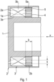
- the housing 2 is part of a rotary actuator 10, as is shown in 3 shown and described below, and corresponds to its housing 11.
- the transmission output shaft 1 corresponds to the planet carrier 14 in 3 .
- the roller bearing 3 has an inner ring 3a, which is arranged on the transmission output shaft 1, and an outer ring 3b, which is arranged in a bore (without reference number) of the housing 2.
- the transmission output member 1 has a shoulder 1a on which the inner ring 3a is supported in the axial direction.
- the inner ring 3a is fixed in the axial direction by a first securing element 4, designed as a securing nut 4, which is screwed onto the transmission output shaft 1.
- the housing 2 has a stop 2a, on which the outer ring 3b rests.
- the inner ring 3a is thus fixed in the axial direction on the transmission output member 1 and the outer ring 3b relative to the housing 2 in the axial direction.
- the lock nut 4 has an outer profile 6 designed as a driving profile, which—according to a preferred embodiment—has a multiplicity of acute-angled notches 6a, pointed notches 6a, running in the axial direction.
- the threaded ring 5 has an inner profile 7 designed as a driver profile, which--according to a preferred embodiment--has a multiplicity of semicircular notches 7a, round notches 7a.
- the outer profile 6 and the inner profile 7 are used to produce a form-fitting connection with a correspondingly profiled tool, with which the securing elements are screwed and clamped in relation to the inner or outer ring.
- a single tool can be used for both securing elements 4, 5.
- the shape of the notches 6a, 7a can be replaced by other profile elements.
- the oscillating motor 10 has an approximately cylindrical housing 11 in which an electric motor 12 and a multi-stage planetary gear 13 are arranged.
- the planetary gear 13 which can be driven by the electric motor 12, has a gear output member designed as a planetary carrier 14 14, which - which is not shown - is connected to a first stabilizer half.
- the second stabilizer half (not shown) is connected to the end face 11a of the housing 11 .
- the planetary carrier 14 is mounted relative to the housing 11 via a double-row angular contact ball bearing 15 and is axially fixed relative to the planetary carrier 14 by a first securing element 16 and relative to the housing 11 by a second securing element 17 .
- the fuse elements 16, 17 according to the prior art 3 replaced by the securing elements 4 and 5 according to the invention.
- the transmission output member 1 corresponds to the planetary carrier 14, the housing 2 to the housing 11 and the roller bearing 3 to the angular contact ball bearing 15.
- the bearing arrangement according to 1 and 2 In particular with the second designed as a threaded ring 5 securing element 5 is thus part of the rotary actuator 10 according to an active roll stabilization of a motor vehicle 3 .
Landscapes
- Engineering & Computer Science (AREA)
- General Engineering & Computer Science (AREA)
- Mechanical Engineering (AREA)
- Retarders (AREA)
Description
- Die Erfindung betrifft einen Drehaktuator einer Wankstabilisierung für ein Kraftfahrzeug nach dem Oberbegriff des Patentanspruches 1.
- Es ist bekannt, Getriebewellen gegenüber einem Gehäuse über ein Wälzlager, welches einen auf der Welle angeordneten Innenring und einen im Gehäuse angeordneten Außenring aufweist, zu lagern. Zur axialen Sicherung des Innenringes weist die Welle eine Wellenschulter auf, gegenüber welcher sich der Innenring nach einer Seite hin abstützt, während auf der anderen Seite ein Sicherungselement, beispielsweise ein Sicherungsring, auch Sprengring genannt, in einer Ringnut der Welle angeordnet ist. In ähnlicher Weise wird der Außenring des Wälzlagers im Gehäuse fixiert, wobei ebenfalls ein Sprengring, ausgebildet für eine Ringnut in einer Bohrung, verwendet wird. Derartige Sicherungsringe weisen den Vorteil eines geringen Bauraumbedarfes auf, da sie in axialer Richtung nur eine geringe Breite beanspruchen. Andererseits besteht die Gefahr, dass Sicherungsringe nicht die erforderliche konstante Anpresskraft aufbringen und infolge einer Wanderbewegung aus ihrer Ringnut austreten.
- Durch die
DE 198 50 169 C1 wurde ein Drehaktuator, auch Schwenkmotor genannt, für eine Wankstabilisierung eines Kraftfahrzeuges bekannt, wobei der Drehaktuator zwischen zwei Hälften eines Stabilisators, ausgebildet als Torsionsstabhälften, angeordnet ist. Der Drehaktuator weist einen Elektromotor sowie ein mehrstufiges Planetengetriebe auf, welches ausgangsseitig mit einer Stabilisatorhälfte drehfest verbunden ist. Das Getriebeausgangsglied, ausgebildet als Planetenträger, ist über Wälzlager gegenüber dem Gehäuse gelagert, wobei Innen- und Außenringe über Sicherungselemente gegenüber dem Planetenträger und dem Gehäuse in axialer Richtung fixiert sind. - Aus
DE 10 2014 202 829 A1 ist ein Drehaktuator einer Wankstabilisierung für ein Kraftfahrzeug bekannt. Ein Innenring des dort gezeigten Wälzlagers zur Lagerung des Planetenträgers wird axial durch ein Vorspannelement vorgespannt. Das Vorspannelement umfasst eine Überwurfmutter und ein Federelement. Die Überwurfmutter ist gegen einen Anschlag geschraubt und befindet sich so in einer axial fest definierten Position auf dem Planetenträger, um mittels des Federelements eine definierte Vorspannkraft auf den Innenring auszuüben. Ein Außenring des Wälzlagers weist zwei Kugelrillen auf. Axial daran angrenzend befindet sich ein nicht bezeichnetes Bauteil. Ob und wie der Außenring des Lagers innerhalb des Gehäuses gesichert ist, lässt sich dem Dokument nicht klar entnehmen. - Durch die den Oberbegriff des Anspruchs 1 aufzeigende Patentschrift
DE 10 2014 205 261 A1 der Anmelderin wurde ebenfalls ein Schwenkmotor eines Wankstabilisators für Kraftfahrzeuge bekannt, wobei das als Planetenträger ausgebildete Getriebeausgangsglied über ein zweireihiges Schrägkugellager gegenüber dem Gehäuse gelagert und durch Sicherungsringe gegenüber dem Gehäuse axial fixiert ist. - Eine Aufgabe der Erfindung besteht darin, bei einem Drehaktuator der eingangs genannten Art die Sicherung des Wälzlagers weiter zu verbessern.
- Die Erfindung umfasst die Merkmale des Patentanspruches 1.
- Erfindungsgemäß ist vorgesehen, dass der Außenring des Wälzlagers gegenüber dem Gehäuse des Drehaktuators mittels eines Gewinderinges gesichert wird, wobei das Gehäuse ein Innengewinde und der Gewindering, auch Ringschraube genannt, ein Außengewinde aufweist und in das Gehäuse eingeschraubt werden kann. Durch Wahl des Anzugmomentes des Gewinderinges kann die Vorspannung, welche auf den Außenring wirkt, eingestellt werden. Der Gewindering ist an sich aufgrund seiner Vorspannung gegen Losdrehen gesichert, kann jedoch durch weitere geeignete, an sich bekannte Sicherungsmittel zusätzlich gesichert werden, beispielsweise eine aushärtende Klebemasse. Im Unterschied zu dem bekannten Sicherungsring kann durch den erfindungsgemäßen Gewindering kein Verlust des Sicherungselements auftreten.
- Erfindungsgemäß ist das erste Sicherungselement, welches den Innenring auf dem Getriebeausgangsglied sichert, als Sicherungsmutter ausgebildet. Der Innenring des Wälzlagers stützt sich einerseits an einer Wellenschulter ab und wird andererseits durch eine Sicherungsmutter gegen die Wellenschulter gepresst. Auf dem Getriebeausgangsglied ist ein Gewinde angeordnet, auf welches die Sicherungsmutter aufgeschraubt und gesichert wird.
- Erfindungsgemäß ist zwischen der Sicherungsmutter und dem Gewindering ein Ring- oder Radialspalt belassen; damit ist sichergestellt, dass beide schraubbaren Sicherungselemente frei gegeneinander verdrehbar sind und andererseits genügend Raum in radialer Richtung vorhanden ist, um ein Werkzeug, z. B. in Form eines Steckschlüssels einzuführen.
- Erfindungsgemäß weisen der Gewindering und die Sicherungsmutter ungefähr die gleiche Breite, d. h. die gleiche Erstreckung in axialer Richtung auf. Geht man davon aus, dass der Innenring eines Wälzlagers in der Regel durch eine Sicherungsmutter auf der Welle fixiert wird, so bedeutet die erfindungsgemäße Anordnung eines Gewinderinges mit Außengewinde zur Sicherung des Außenringes keinen zusätzlichen Bauraum.
- Erfindungsgemäß weist die Sicherungsmutter ein Außenprofil auf, welches als Mitnahmeprofil für den Eingriff eines Drehwerkzeuges zum Festziehen der Sicherungsmutter ausgebildet ist. Damit wird erreicht, dass die Sicherungsmutter auf einfache Weise montiert werden kann.
- Erfindungsgemäß weist der Gewindering ein Innenprofil auf, welches als Mitnahmeprofil für den Eingriff eines weiteren Drehwerkzeuges ausgebildet ist. Damit wird erreicht, dass der Gewindering ebenfalls leicht montiert und mit einem definierten Drehmoment angezogen werden kann. Als weiterer Vorteil ergibt sich die Möglichkeit, sowohl die Sicherungsmutter auf der Welle als auch den Gewindering in der Gehäusebohrung gleichzeitig, d. h. mit einem Werkzeug anzuziehen, wobei das Werkzeug einerseits ein inneres Mitnahmeprofil für die Sicherungsmutter und andererseits ein äußeres Mitnahmeprofil für den Gewindering aufweist.
- Erfindungsgemäß ist das Getriebeausgangsglied Teil eines Planetengetriebes des Schwenkmotors respektive des Drehaktuators. Bevorzugt ist das Getriebeausgangsglied als Planetenträger des mehrstufigen Planetengetriebes ausgebildet. Der Planetenträger ist einer erhöhten Belastung durch Radialkräfte und Biegemomente ausgesetzt - dementsprechend ist die Wälzlagerung beanspruchungsgerecht auszulegen und zu sichern. Diese Forderung wird durch den erfindungsgemäßen Gewindering in besonderem Maße erfüllt, womit ein wesentlicher Beitrag für die Sicherheit dieser Komponente einer aktiven Wankstabilisierung geleistet wird.
- Ein Ausführungsbeispiel der Erfindung ist in der Zeichnung dargestellt und wird im Folgenden näher beschrieben, wobei sich aus der Beschreibung und/oder der Zeichnung weitere Merkmale und/oder Vorteile ergeben können. Es zeigen
- Fig. 1
- einen Axialschnitt einer Lagerung eines Planetenträgers in einem Gehäuse eines Drehaktuators,
- Fig. 2
- eine Ansicht in axialer Richtung auf die Sicherungselemente von Innen- und Außenring des Wälzlagers und
- Fig. 3
- einen Drehaktuator einer Wankstabilisierung nach dem Stand der Technik.
-
Fig. 1 zeigt eine Anordnung zur Lagerung eines Getriebeausgangsgliedes, insbesondere einer Getriebeausgangswelle 1 in einem Gehäuse 2 mittels eines Wälzlagers 3, ausgebildet als zweireihiges Schrägkugellager 3. Das Gehäuse 2 ist Teil eines Drehaktuators 10, wie er inFig. 3 dargestellt und unten beschrieben ist, und entspricht dessen Gehäuse 11.Die Getriebeausgangswelle 1 entspricht dem Planetenträger 14 inFig. 3 . Das Wälzlager 3 weist einen Innenring 3a auf, welcher auf der Getriebeausgangswelle 1 angeordnet ist, sowie einen Außenring 3b, welcher in einer Bohrung (ohne Bezugszahl) des Gehäuses 2 angeordnet ist. Das Getriebeausgangsglied 1 weist eine Schulter 1a auf, an welcher sich der Innenring 3a in axialer Richtung abstützt. Durch ein erstes Sicherungselement 4, ausgebildet als Sicherungsmutter 4, welche auf die Getriebeausgangswelle 1 aufgeschraubt ist, wird der Innenring 3a in axialer Richtung fixiert. Das Gehäuse 2 weist einen Anschlag 2a auf, an welchem der Außenring 3b anliegt. Ein zweites Sicherungselement 5, ausgebildet als Gewindering 5 mit einem Außengewinde 5a, ist in ein Innengewinde 2a des Gehäuses 2 eingeschraubt und verspannt den Außenring 3b gegenüber dem Anschlag 2a. Der Innenring 3a ist somit in axialer Richtung auf dem Getriebeausgangsglied 1 und der Außenring 3b gegenüber dem Gehäuse 2 in axialer Richtung fixiert. Zwischen der Sicherungsmutter 4 und dem Gewindering 5 ist ein Ringspalt s belassen, in welchen ein nicht dargestelltes Drehwerkzeug zum Anziehen der Sicherungselemente 4, 5 zwecks Erzeugung einer Vorspannung einführbar ist. Beide Sicherungselemente, d. h. die Sicherungsmutter 4 und der Gewindering 5, auch Ringschraube 5 genannt, weisen etwa die gleiche Breite b auf, insofern benötigen beide koaxial angeordneten Sicherungselemente 4, 5 denselben Bauraum in axialer Richtung. -
Fig. 2 zeigt eine Ansicht in axialer Richtung, d. h. in Richtung des Pfeils X inFig. 1 auf die Lageranordnung mit dem Gewindering 5 und der Sicherungsmutter 4, zwischen denen der Ringspalt s belassen ist. Die Sicherungsmutter 4 weist ein als Mitnahmeprofil ausgebildetes Außenprofil 6 auf, welches - nach einer bevorzugten Ausführungsform - eine Vielzahl von spitzwinkligen, in Axialrichtung verlaufenden Kerben 6a, Spitzkerben 6a, aufweist. Der Gewindering 5 weist ein als Mitnahmeprofil ausgebildetes Innenprofil 7 auf, welches - nach einer bevorzugten Ausführungsform - eine Vielzahl von halbkreisförmig ausgebildeten Kerben 7a, Rundkerben 7a, aufweist. Das Außenprofil 6 und das Innenprofil 7 dienen der Herstellung einer formschlüssigen Verbindung mit einem entsprechend profilierten Werkzeug, mit dem die Sicherungselemente gegenüber dem Innen- bzw. dem Außenring verschraubt und verspannt werden. Nach einer bevorzugten Ausführungsform kann ein einziges Werkzeug für beide Sicherungselemente 4, 5 verwendet werden. Die Kerben 6a, 7a können hinsichtlich ihrer Form durch andere Profilelemente ersetzt werden. -
Fig. 3 zeigt einen Drehaktuator 10, auch Schwenkmotor 10 genannt, nach dem Stand der Technik, bekannt durch die eingangs genannteDE 10 2014 205 261 A1 der Anmelderin. Der Schwenkmotor 10 weist ein etwa zylinderförmig ausgebildetes Gehäuse 11 auf, in welchem ein Elektromotor 12 und ein mehrstufiges Planetengetriebe 13 angeordnet sind. Das Planetengetriebe 13, welches durch den Elektromotor 12 antreibbar ist, weist ein als Planetenträger 14 ausgebildetes Getriebeausgangsglied 14 auf, welches - was nicht dargestellt ist - mit einer ersten Stabilisatorhälfte verbunden wird. Die zweite Stabilisatorhälfte (nicht dargestellt) ist mit der Stirnseite 11a des Gehäuses 11 verbunden. Der Planetenträger 14 ist über ein zweireihiges Schrägkugellager 15 gegenüber dem Gehäuse 11 gelagert und über ein erstes Sicherungselement 16 gegenüber dem Planetenträger 14 und ein zweites Sicherungselement 17 gegenüber dem Gehäuse 11 axial fixiert. - Erfindungsgemäß werden die Sicherungselemente 16, 17 nach dem Stand der Technik gemäß
Fig. 3 ersetzt durch die erfindungsgemäßen Sicherungselemente 4 und 5. Dabei entsprechen - wie oben erwähnt - das Getriebeausgangsglied 1 dem Planetenträger 14, das Gehäuse 2 dem Gehäuse 11 und das Wälzlager 3 dem Schrägkugellager 15. Die Lageranordnung gemäßFig. 1 undFig. 2 , insbesondere mit dem zweiten als Gewindering 5 ausgebildeten Sicherungselement 5 ist damit Teil des Drehaktuators 10 einer aktiven Wankstabilisierung eines Kraftfahrzeuges gemäßFig. 3 . -
- 1
- Getriebeausgangsglied
- 1a
- Schulter
- 2
- Gehäuse
- 2a
- Anschlag/Gehäuse
- 2b
- Innengewinde/Gehäuse
- 3
- Wälzlager
- 3a
- Innenring
- 3b
- Außenring
- 4
- erstes Sicherungselement/Sicherungsmutter
- 5
- zweites Sicherungselement/Gewindering
- 6
- Außenprofil
- 6a
- Spitzkerbe
- 7
- Innenprofil
- 7a
- Rundkerbe
- 10
- Drehaktuator/Schwenkmotor
- 11
- Gehäuse
- 11a
- Stirnseite
- 12
- Elektromotor
- 13
- Planetengetriebe
- 14
- Planetenträger
- 15
- Wälzlager
- 16
- erstes Sicherungselement
- 17
- zweites Sicherungselement
- s
- Ringspalt
- b
- Breite der Sicherungselemente
Claims (1)
- Drehaktuator für eine Wankstabilisierung für ein Kraftfahrzeug, wobei der Drehaktuator ein Wälzlager, eine Anordnung zur Sicherung des Wälzlagers (3), ein Gehäuse (2) und ein Getriebeausgangsglied umfasst, das Wälzlager aufweisend einen Innenring (3a) und einen Außenring (3b), wobei sich in dem Gehäuse (2) die Anordnung zur Lagerung des Getriebeausgangsglieds mittels des Wälzlagers befindet, wobei der Innenring (3a) auf einem Getriebeausgangsglied (1) angeordnet und durch ein erstes Sicherungselement (4) axial fixiert und der Außenring (3b) in einer Bohrung des Gehäuses (2) angeordnet und durch ein zweites Sicherungselement (5) axial fixiert ist, wobei am Gehäuse (2) ein Anschlag (2a) ausgebildet ist, an dem der Außenring (3b) anliegt, wobei das Getriebeausgangsglied (1) als Planetenträger eines Planetengetriebes des Drehaktuators in Form einer Getriebeausgangswelle ausgebildet ist und eine Schulter (1a) aufweist, an welcher sich der Innenring (3a) in axialer Richtung abstützt, dadurch gekennzeichnet, dass das erste Sicherungselement (4) als Sicherungsmutter ausgebildet ist, welche auf die Getriebeausgangswelle (1) aufgeschraubt ist, wobei das zweite Sicherungselement als Gewindering (5) mit einem Außengewinde (5a) ausgebildet ist, wobei im Gehäuse (2) ein Innengewinde (2b) angeordnet ist und wobei der Gewindering (5) in das Innengewinde (2b) des Gehäuses (2) einschraubbar und gegen den Außenring (3b) verspannbar ist, um den Außenring (3b) gegenüber dem Anschlag (2a) zu verspannen, wobei zwischen dem ersten Sicherungselement (4) und dem Gewindering (5) ein Ringspalt (s) belassen ist, in welchen ein Drehwerkzeug zum Anziehen der Sicherungselemente (4, 5) zwecks Erzeugung einer Vorspannung einführbar ist, wobei beide Sicherungselemente (4, 5) etwa die gleiche Breite (b) aufweisen, und wobei die Sicherungsmutter (4) ein als Mitnahmeprofil ausgebildetes Außenprofil und der Gewindering (5) ein als Mitnahmeprofil ausgebildetes Innenprofil aufweist.
Applications Claiming Priority (2)
| Application Number | Priority Date | Filing Date | Title |
|---|---|---|---|
| DE102017209686.1A DE102017209686A1 (de) | 2017-06-08 | 2017-06-08 | Drehaktuator einer Wankstabilisierung für ein Kraftfahrzeug |
| PCT/EP2018/061691 WO2018224226A1 (de) | 2017-06-08 | 2018-05-07 | Drehaktuator einer wankstabilisierung für ein kraftfahrzeug |
Publications (2)
| Publication Number | Publication Date |
|---|---|
| EP3634789A1 EP3634789A1 (de) | 2020-04-15 |
| EP3634789B1 true EP3634789B1 (de) | 2023-06-07 |
Family
ID=62152542
Family Applications (1)
| Application Number | Title | Priority Date | Filing Date |
|---|---|---|---|
| EP18724189.8A Active EP3634789B1 (de) | 2017-06-08 | 2018-05-07 | Drehaktuator einer wankstabilisierung für ein kraftfahrzeug |
Country Status (3)
| Country | Link |
|---|---|
| EP (1) | EP3634789B1 (de) |
| DE (1) | DE102017209686A1 (de) |
| WO (1) | WO2018224226A1 (de) |
Families Citing this family (1)
| Publication number | Priority date | Publication date | Assignee | Title |
|---|---|---|---|---|
| DE102020202910B4 (de) * | 2020-03-06 | 2025-12-04 | Zf Friedrichshafen Ag | Drehaktuator für eine Wankstabilisierung eines Kraftfahrzeugs |
Family Cites Families (17)
| Publication number | Priority date | Publication date | Assignee | Title |
|---|---|---|---|---|
| DE1047213B (de) * | 1956-07-17 | 1958-12-24 | Maschf Augsburg Nuernberg Ag | Lagerung der Zylinder von Druckmaschinen |
| DE2603685A1 (de) * | 1976-01-31 | 1977-08-04 | Kugelfischer G Schaefer & Co | Befestigung zweier schraeglager |
| US4160608A (en) * | 1978-02-03 | 1979-07-10 | Fmc Corporation | Preloading nut for wedge sleeve |
| EP0245402A1 (de) * | 1985-11-16 | 1987-11-19 | ZF FRIEDRICHSHAFEN Aktiengesellschaft | Verfahren und vorrichtung zur einstellung und justierung von getriebeelementen |
| JP2586503B2 (ja) * | 1987-08-17 | 1997-03-05 | 日本精工株式会社 | 軸受の取付装置 |
| DE9216915U1 (de) * | 1992-12-11 | 1993-02-11 | Knott GmbH, 8201 Eggstätt | Radnabenlager, insbesondere für Anhängerachsen |
| JPH07284244A (ja) * | 1994-04-05 | 1995-10-27 | Mitsuba Electric Mfg Co Ltd | モータ回転軸の支持構造およびその製造方法 |
| WO1998025772A1 (en) * | 1996-12-10 | 1998-06-18 | Kelsey Hayes Company | Vehicle wheel hub and bearing retention system and method for producing same |
| DE19850169C1 (de) | 1998-10-30 | 2000-07-27 | Heynau Antriebstechnik Gmbh | Antriebsaggregat |
| DE10251387B4 (de) * | 2002-11-01 | 2006-04-27 | Ralf Kosan | Elektrische Preßvorrichtung |
| DE102006055733A1 (de) * | 2006-11-25 | 2008-05-29 | Zf Friedrichshafen Ag | Stabilisatoranordnung |
| DE102007031203A1 (de) * | 2007-07-04 | 2009-01-08 | Zf Friedrichshafen Ag | Stabilisatoranordnung |
| DE102013201520A1 (de) * | 2013-01-30 | 2014-07-31 | Schaeffler Technologies Gmbh & Co. Kg | Umlaufrädergetriebe |
| DE102014202829B4 (de) * | 2014-02-17 | 2026-01-08 | Schaeffler Technologies AG & Co. KG | Wankstabilisator für ein Kraftfahrzeug |
| DE102014205261A1 (de) | 2014-03-20 | 2015-09-24 | Zf Friedrichshafen Ag | Schwenkmotor eines aktiven Wankstabilisators für Kraftfahrzeuge |
| DE102014205262A1 (de) * | 2014-03-20 | 2015-09-24 | Zf Friedrichshafen Ag | Aktiver Wankstabilisator für Kraftfahrzeuge |
| DE102015220176A1 (de) * | 2015-02-20 | 2016-08-25 | Schaeffler Technologies AG & Co. KG | Aktorikvorrichtung für einen Wankstabilisator sowie Wankstabilisator und Fahrzeug |
-
2017
- 2017-06-08 DE DE102017209686.1A patent/DE102017209686A1/de not_active Withdrawn
-
2018
- 2018-05-07 EP EP18724189.8A patent/EP3634789B1/de active Active
- 2018-05-07 WO PCT/EP2018/061691 patent/WO2018224226A1/de not_active Ceased
Also Published As
| Publication number | Publication date |
|---|---|
| DE102017209686A1 (de) | 2018-12-13 |
| WO2018224226A1 (de) | 2018-12-13 |
| EP3634789A1 (de) | 2020-04-15 |
Similar Documents
| Publication | Publication Date | Title |
|---|---|---|
| DE102014206934B4 (de) | Stellmotor | |
| WO2008122277A2 (de) | Radlageranordnung | |
| DE102016200102B4 (de) | Aktuator, insbesondere für eine Hinterachslenkung eines Kraftfahrzeuges | |
| DE102017124388A1 (de) | Elektromechanischer Lenkungsaktuator | |
| EP2025951A2 (de) | Kolben/Zylinder-Einheit | |
| WO2020164654A1 (de) | Planetenwälzgewindetrieb und aktuator für eine hinterachslenkung eines kraftfahrzeuges mit einem derartigen planetenwälzgewindetrieb | |
| DE102019125310A1 (de) | Planetenwälzgetriebe | |
| DE69408577T2 (de) | Toleranzringe | |
| DE10141457A1 (de) | Einstellanordnung für Axialspiel und Vorbelastung bei Lagern | |
| DE102017211461B4 (de) | Lenkgetriebe | |
| EP2527676B1 (de) | Verfahren zum Erzeugen einer mechanischen Spannung und Vorrichtung zum mechanischen Verspannen mindestens einer Verschraubung | |
| EP3634789B1 (de) | Drehaktuator einer wankstabilisierung für ein kraftfahrzeug | |
| DE2530052A1 (de) | Kupplung zum drehfesten verbinden einander zugeordneter abschnitte einer lieferwelle fuer textilmaschinen | |
| WO2009129808A1 (de) | Baueinheit | |
| DE102014225340A1 (de) | Planetengetriebe mit einem einwandigen Planetenträger | |
| WO1990008272A1 (de) | Drehfeste flanschverbindung | |
| EP1845038B1 (de) | Tragrolle für eine Staurollenbahn | |
| DE102014212433A1 (de) | Stabilisator | |
| DE102016212812A1 (de) | Lenkung für ein Kraftfahrzeug, insbesondere für ein Nutzfahrzeug, mit Lenkwelle und Kugelgewindemutter | |
| DE10344726B4 (de) | Zahnstangenlenkung für ein Kraftfahrzeug | |
| DE112014004828B4 (de) | Gratbeständige Befestigungsmittel-montierte Lageranordnung | |
| EP2450584A2 (de) | Lageranordnung für eine Welle | |
| DE102016012978A1 (de) | Planetengetriebe mit einem Planetenträger und einer Planetenradachse | |
| EP3622201B1 (de) | Planetengetriebe und schwenkmotor eines wankstabilisators mit planetengetriebe | |
| WO2016155724A1 (de) | Planetenwälzgewindetrieb (pwg) und aktor mit einem planetenwälzgewindetrieb |
Legal Events
| Date | Code | Title | Description |
|---|---|---|---|
| STAA | Information on the status of an ep patent application or granted ep patent |
Free format text: STATUS: UNKNOWN |
|
| STAA | Information on the status of an ep patent application or granted ep patent |
Free format text: STATUS: THE INTERNATIONAL PUBLICATION HAS BEEN MADE |
|
| PUAI | Public reference made under article 153(3) epc to a published international application that has entered the european phase |
Free format text: ORIGINAL CODE: 0009012 |
|
| STAA | Information on the status of an ep patent application or granted ep patent |
Free format text: STATUS: REQUEST FOR EXAMINATION WAS MADE |
|
| 17P | Request for examination filed |
Effective date: 20191105 |
|
| AK | Designated contracting states |
Kind code of ref document: A1 Designated state(s): AL AT BE BG CH CY CZ DE DK EE ES FI FR GB GR HR HU IE IS IT LI LT LU LV MC MK MT NL NO PL PT RO RS SE SI SK SM TR |
|
| AX | Request for extension of the european patent |
Extension state: BA ME |
|
| DAV | Request for validation of the european patent (deleted) | ||
| DAX | Request for extension of the european patent (deleted) | ||
| STAA | Information on the status of an ep patent application or granted ep patent |
Free format text: STATUS: EXAMINATION IS IN PROGRESS |
|
| 17Q | First examination report despatched |
Effective date: 20210309 |
|
| GRAP | Despatch of communication of intention to grant a patent |
Free format text: ORIGINAL CODE: EPIDOSNIGR1 |
|
| STAA | Information on the status of an ep patent application or granted ep patent |
Free format text: STATUS: GRANT OF PATENT IS INTENDED |
|
| INTG | Intention to grant announced |
Effective date: 20230118 |
|
| GRAS | Grant fee paid |
Free format text: ORIGINAL CODE: EPIDOSNIGR3 |
|
| GRAA | (expected) grant |
Free format text: ORIGINAL CODE: 0009210 |
|
| STAA | Information on the status of an ep patent application or granted ep patent |
Free format text: STATUS: THE PATENT HAS BEEN GRANTED |
|
| AK | Designated contracting states |
Kind code of ref document: B1 Designated state(s): AL AT BE BG CH CY CZ DE DK EE ES FI FR GB GR HR HU IE IS IT LI LT LU LV MC MK MT NL NO PL PT RO RS SE SI SK SM TR |
|
| REG | Reference to a national code |
Ref country code: GB Ref legal event code: FG4D Free format text: NOT ENGLISH |
|
| REG | Reference to a national code |
Ref country code: CH Ref legal event code: EP Ref country code: AT Ref legal event code: REF Ref document number: 1573970 Country of ref document: AT Kind code of ref document: T Effective date: 20230615 Ref country code: DE Ref legal event code: R096 Ref document number: 502018012349 Country of ref document: DE |
|
| REG | Reference to a national code |
Ref country code: LT Ref legal event code: MG9D |
|
| REG | Reference to a national code |
Ref country code: NL Ref legal event code: MP Effective date: 20230607 |
|
| PG25 | Lapsed in a contracting state [announced via postgrant information from national office to epo] |
Ref country code: SE Free format text: LAPSE BECAUSE OF FAILURE TO SUBMIT A TRANSLATION OF THE DESCRIPTION OR TO PAY THE FEE WITHIN THE PRESCRIBED TIME-LIMIT Effective date: 20230607 Ref country code: NO Free format text: LAPSE BECAUSE OF FAILURE TO SUBMIT A TRANSLATION OF THE DESCRIPTION OR TO PAY THE FEE WITHIN THE PRESCRIBED TIME-LIMIT Effective date: 20230907 Ref country code: ES Free format text: LAPSE BECAUSE OF FAILURE TO SUBMIT A TRANSLATION OF THE DESCRIPTION OR TO PAY THE FEE WITHIN THE PRESCRIBED TIME-LIMIT Effective date: 20230607 |
|
| PG25 | Lapsed in a contracting state [announced via postgrant information from national office to epo] |
Ref country code: RS Free format text: LAPSE BECAUSE OF FAILURE TO SUBMIT A TRANSLATION OF THE DESCRIPTION OR TO PAY THE FEE WITHIN THE PRESCRIBED TIME-LIMIT Effective date: 20230607 Ref country code: NL Free format text: LAPSE BECAUSE OF FAILURE TO SUBMIT A TRANSLATION OF THE DESCRIPTION OR TO PAY THE FEE WITHIN THE PRESCRIBED TIME-LIMIT Effective date: 20230607 Ref country code: LV Free format text: LAPSE BECAUSE OF FAILURE TO SUBMIT A TRANSLATION OF THE DESCRIPTION OR TO PAY THE FEE WITHIN THE PRESCRIBED TIME-LIMIT Effective date: 20230607 Ref country code: LT Free format text: LAPSE BECAUSE OF FAILURE TO SUBMIT A TRANSLATION OF THE DESCRIPTION OR TO PAY THE FEE WITHIN THE PRESCRIBED TIME-LIMIT Effective date: 20230607 Ref country code: HR Free format text: LAPSE BECAUSE OF FAILURE TO SUBMIT A TRANSLATION OF THE DESCRIPTION OR TO PAY THE FEE WITHIN THE PRESCRIBED TIME-LIMIT Effective date: 20230607 Ref country code: GR Free format text: LAPSE BECAUSE OF FAILURE TO SUBMIT A TRANSLATION OF THE DESCRIPTION OR TO PAY THE FEE WITHIN THE PRESCRIBED TIME-LIMIT Effective date: 20230908 |
|
| PG25 | Lapsed in a contracting state [announced via postgrant information from national office to epo] |
Ref country code: FI Free format text: LAPSE BECAUSE OF FAILURE TO SUBMIT A TRANSLATION OF THE DESCRIPTION OR TO PAY THE FEE WITHIN THE PRESCRIBED TIME-LIMIT Effective date: 20230607 |
|
| PG25 | Lapsed in a contracting state [announced via postgrant information from national office to epo] |
Ref country code: SK Free format text: LAPSE BECAUSE OF FAILURE TO SUBMIT A TRANSLATION OF THE DESCRIPTION OR TO PAY THE FEE WITHIN THE PRESCRIBED TIME-LIMIT Effective date: 20230607 |
|
| PG25 | Lapsed in a contracting state [announced via postgrant information from national office to epo] |
Ref country code: IS Free format text: LAPSE BECAUSE OF FAILURE TO SUBMIT A TRANSLATION OF THE DESCRIPTION OR TO PAY THE FEE WITHIN THE PRESCRIBED TIME-LIMIT Effective date: 20231007 |
|
| PG25 | Lapsed in a contracting state [announced via postgrant information from national office to epo] |
Ref country code: SM Free format text: LAPSE BECAUSE OF FAILURE TO SUBMIT A TRANSLATION OF THE DESCRIPTION OR TO PAY THE FEE WITHIN THE PRESCRIBED TIME-LIMIT Effective date: 20230607 Ref country code: SK Free format text: LAPSE BECAUSE OF FAILURE TO SUBMIT A TRANSLATION OF THE DESCRIPTION OR TO PAY THE FEE WITHIN THE PRESCRIBED TIME-LIMIT Effective date: 20230607 Ref country code: RO Free format text: LAPSE BECAUSE OF FAILURE TO SUBMIT A TRANSLATION OF THE DESCRIPTION OR TO PAY THE FEE WITHIN THE PRESCRIBED TIME-LIMIT Effective date: 20230607 Ref country code: PT Free format text: LAPSE BECAUSE OF FAILURE TO SUBMIT A TRANSLATION OF THE DESCRIPTION OR TO PAY THE FEE WITHIN THE PRESCRIBED TIME-LIMIT Effective date: 20231009 Ref country code: IS Free format text: LAPSE BECAUSE OF FAILURE TO SUBMIT A TRANSLATION OF THE DESCRIPTION OR TO PAY THE FEE WITHIN THE PRESCRIBED TIME-LIMIT Effective date: 20231007 Ref country code: EE Free format text: LAPSE BECAUSE OF FAILURE TO SUBMIT A TRANSLATION OF THE DESCRIPTION OR TO PAY THE FEE WITHIN THE PRESCRIBED TIME-LIMIT Effective date: 20230607 Ref country code: CZ Free format text: LAPSE BECAUSE OF FAILURE TO SUBMIT A TRANSLATION OF THE DESCRIPTION OR TO PAY THE FEE WITHIN THE PRESCRIBED TIME-LIMIT Effective date: 20230607 |
|
| PG25 | Lapsed in a contracting state [announced via postgrant information from national office to epo] |
Ref country code: PL Free format text: LAPSE BECAUSE OF FAILURE TO SUBMIT A TRANSLATION OF THE DESCRIPTION OR TO PAY THE FEE WITHIN THE PRESCRIBED TIME-LIMIT Effective date: 20230607 |
|
| REG | Reference to a national code |
Ref country code: DE Ref legal event code: R097 Ref document number: 502018012349 Country of ref document: DE |
|
| PLBE | No opposition filed within time limit |
Free format text: ORIGINAL CODE: 0009261 |
|
| STAA | Information on the status of an ep patent application or granted ep patent |
Free format text: STATUS: NO OPPOSITION FILED WITHIN TIME LIMIT |
|
| PG25 | Lapsed in a contracting state [announced via postgrant information from national office to epo] |
Ref country code: DK Free format text: LAPSE BECAUSE OF FAILURE TO SUBMIT A TRANSLATION OF THE DESCRIPTION OR TO PAY THE FEE WITHIN THE PRESCRIBED TIME-LIMIT Effective date: 20230607 |
|
| PG25 | Lapsed in a contracting state [announced via postgrant information from national office to epo] |
Ref country code: SI Free format text: LAPSE BECAUSE OF FAILURE TO SUBMIT A TRANSLATION OF THE DESCRIPTION OR TO PAY THE FEE WITHIN THE PRESCRIBED TIME-LIMIT Effective date: 20230607 |
|
| 26N | No opposition filed |
Effective date: 20240308 |
|
| PG25 | Lapsed in a contracting state [announced via postgrant information from national office to epo] |
Ref country code: SI Free format text: LAPSE BECAUSE OF FAILURE TO SUBMIT A TRANSLATION OF THE DESCRIPTION OR TO PAY THE FEE WITHIN THE PRESCRIBED TIME-LIMIT Effective date: 20230607 Ref country code: IT Free format text: LAPSE BECAUSE OF FAILURE TO SUBMIT A TRANSLATION OF THE DESCRIPTION OR TO PAY THE FEE WITHIN THE PRESCRIBED TIME-LIMIT Effective date: 20230607 |
|
| PG25 | Lapsed in a contracting state [announced via postgrant information from national office to epo] |
Ref country code: BG Free format text: LAPSE BECAUSE OF FAILURE TO SUBMIT A TRANSLATION OF THE DESCRIPTION OR TO PAY THE FEE WITHIN THE PRESCRIBED TIME-LIMIT Effective date: 20230607 |
|
| PG25 | Lapsed in a contracting state [announced via postgrant information from national office to epo] |
Ref country code: BG Free format text: LAPSE BECAUSE OF FAILURE TO SUBMIT A TRANSLATION OF THE DESCRIPTION OR TO PAY THE FEE WITHIN THE PRESCRIBED TIME-LIMIT Effective date: 20230607 |
|
| REG | Reference to a national code |
Ref country code: CH Ref legal event code: PL |
|
| PG25 | Lapsed in a contracting state [announced via postgrant information from national office to epo] |
Ref country code: MC Free format text: LAPSE BECAUSE OF FAILURE TO SUBMIT A TRANSLATION OF THE DESCRIPTION OR TO PAY THE FEE WITHIN THE PRESCRIBED TIME-LIMIT Effective date: 20230607 |
|
| PG25 | Lapsed in a contracting state [announced via postgrant information from national office to epo] |
Ref country code: LU Free format text: LAPSE BECAUSE OF NON-PAYMENT OF DUE FEES Effective date: 20240507 |
|
| GBPC | Gb: european patent ceased through non-payment of renewal fee |
Effective date: 20240507 |
|
| PG25 | Lapsed in a contracting state [announced via postgrant information from national office to epo] |
Ref country code: MC Free format text: LAPSE BECAUSE OF FAILURE TO SUBMIT A TRANSLATION OF THE DESCRIPTION OR TO PAY THE FEE WITHIN THE PRESCRIBED TIME-LIMIT Effective date: 20230607 Ref country code: LU Free format text: LAPSE BECAUSE OF NON-PAYMENT OF DUE FEES Effective date: 20240507 Ref country code: CH Free format text: LAPSE BECAUSE OF NON-PAYMENT OF DUE FEES Effective date: 20240531 |
|
| REG | Reference to a national code |
Ref country code: BE Ref legal event code: MM Effective date: 20240531 |
|
| PG25 | Lapsed in a contracting state [announced via postgrant information from national office to epo] |
Ref country code: IE Free format text: LAPSE BECAUSE OF NON-PAYMENT OF DUE FEES Effective date: 20240507 |
|
| PG25 | Lapsed in a contracting state [announced via postgrant information from national office to epo] |
Ref country code: BE Free format text: LAPSE BECAUSE OF NON-PAYMENT OF DUE FEES Effective date: 20240531 |
|
| PG25 | Lapsed in a contracting state [announced via postgrant information from national office to epo] |
Ref country code: FR Free format text: LAPSE BECAUSE OF NON-PAYMENT OF DUE FEES Effective date: 20240531 |
|
| PG25 | Lapsed in a contracting state [announced via postgrant information from national office to epo] |
Ref country code: GB Free format text: LAPSE BECAUSE OF NON-PAYMENT OF DUE FEES Effective date: 20240507 |
|
| PGFP | Annual fee paid to national office [announced via postgrant information from national office to epo] |
Ref country code: DE Payment date: 20250311 Year of fee payment: 8 |
|
| REG | Reference to a national code |
Ref country code: AT Ref legal event code: MM01 Ref document number: 1573970 Country of ref document: AT Kind code of ref document: T Effective date: 20240507 |
|
| PG25 | Lapsed in a contracting state [announced via postgrant information from national office to epo] |
Ref country code: AT Free format text: LAPSE BECAUSE OF NON-PAYMENT OF DUE FEES Effective date: 20240507 |
|
| PG25 | Lapsed in a contracting state [announced via postgrant information from national office to epo] |
Ref country code: CY Free format text: LAPSE BECAUSE OF FAILURE TO SUBMIT A TRANSLATION OF THE DESCRIPTION OR TO PAY THE FEE WITHIN THE PRESCRIBED TIME-LIMIT; INVALID AB INITIO Effective date: 20180507 |
|
| PG25 | Lapsed in a contracting state [announced via postgrant information from national office to epo] |
Ref country code: HU Free format text: LAPSE BECAUSE OF FAILURE TO SUBMIT A TRANSLATION OF THE DESCRIPTION OR TO PAY THE FEE WITHIN THE PRESCRIBED TIME-LIMIT; INVALID AB INITIO Effective date: 20180507 |