EP3635193B1 - Revêtement mural - Google Patents
Revêtement mural Download PDFInfo
- Publication number
- EP3635193B1 EP3635193B1 EP18733676.3A EP18733676A EP3635193B1 EP 3635193 B1 EP3635193 B1 EP 3635193B1 EP 18733676 A EP18733676 A EP 18733676A EP 3635193 B1 EP3635193 B1 EP 3635193B1
- Authority
- EP
- European Patent Office
- Prior art keywords
- fitting
- corner
- wall cladding
- rib
- protective
- Prior art date
- Legal status (The legal status is an assumption and is not a legal conclusion. Google has not performed a legal analysis and makes no representation as to the accuracy of the status listed.)
- Active
Links
Images


Classifications
-
- E—FIXED CONSTRUCTIONS
- E04—BUILDING
- E04F—FINISHING WORK ON BUILDINGS, e.g. STAIRS, FLOORS
- E04F13/00—Coverings or linings, e.g. for walls or ceilings
- E04F13/07—Coverings or linings, e.g. for walls or ceilings composed of covering or lining elements; Sub-structures therefor; Fastening means therefor
- E04F13/21—Fastening means specially adapted for covering or lining elements
- E04F13/24—Hidden fastening means on the rear of the covering or lining elements
-
- E—FIXED CONSTRUCTIONS
- E04—BUILDING
- E04F—FINISHING WORK ON BUILDINGS, e.g. STAIRS, FLOORS
- E04F13/00—Coverings or linings, e.g. for walls or ceilings
- E04F13/07—Coverings or linings, e.g. for walls or ceilings composed of covering or lining elements; Sub-structures therefor; Fastening means therefor
- E04F13/072—Coverings or linings, e.g. for walls or ceilings composed of covering or lining elements; Sub-structures therefor; Fastening means therefor composed of specially adapted, structured or shaped covering or lining elements
- E04F13/073—Coverings or linings, e.g. for walls or ceilings composed of covering or lining elements; Sub-structures therefor; Fastening means therefor composed of specially adapted, structured or shaped covering or lining elements for particular building parts, e.g. corners or columns
- E04F13/0733—Coverings or linings, e.g. for walls or ceilings composed of covering or lining elements; Sub-structures therefor; Fastening means therefor composed of specially adapted, structured or shaped covering or lining elements for particular building parts, e.g. corners or columns for corners
-
- E—FIXED CONSTRUCTIONS
- E04—BUILDING
- E04F—FINISHING WORK ON BUILDINGS, e.g. STAIRS, FLOORS
- E04F13/00—Coverings or linings, e.g. for walls or ceilings
- E04F13/07—Coverings or linings, e.g. for walls or ceilings composed of covering or lining elements; Sub-structures therefor; Fastening means therefor
- E04F13/08—Coverings or linings, e.g. for walls or ceilings composed of covering or lining elements; Sub-structures therefor; Fastening means therefor composed of a plurality of similar covering or lining elements
- E04F13/0801—Separate fastening elements
- E04F13/0803—Separate fastening elements with load-supporting elongated furring elements between wall and covering elements
- E04F13/0805—Separate fastening elements with load-supporting elongated furring elements between wall and covering elements with additional fastening elements between furring elements and the wall
-
- E—FIXED CONSTRUCTIONS
- E04—BUILDING
- E04F—FINISHING WORK ON BUILDINGS, e.g. STAIRS, FLOORS
- E04F13/00—Coverings or linings, e.g. for walls or ceilings
- E04F13/07—Coverings or linings, e.g. for walls or ceilings composed of covering or lining elements; Sub-structures therefor; Fastening means therefor
- E04F13/08—Coverings or linings, e.g. for walls or ceilings composed of covering or lining elements; Sub-structures therefor; Fastening means therefor composed of a plurality of similar covering or lining elements
- E04F13/0801—Separate fastening elements
- E04F13/0803—Separate fastening elements with load-supporting elongated furring elements between wall and covering elements
- E04F13/081—Separate fastening elements with load-supporting elongated furring elements between wall and covering elements with additional fastening elements between furring elements and covering elements
- E04F13/083—Hooking means on the back side of the covering elements
-
- E—FIXED CONSTRUCTIONS
- E04—BUILDING
- E04B—GENERAL BUILDING CONSTRUCTIONS; WALLS, e.g. PARTITIONS; ROOFS; FLOORS; CEILINGS; INSULATION OR OTHER PROTECTION OF BUILDINGS
- E04B2/00—Walls, e.g. partitions, for buildings; Wall construction with regard to insulation; Connections specially adapted to walls
- E04B2/74—Removable non-load-bearing partitions; Partitions with a free upper edge
- E04B2/7407—Removable non-load-bearing partitions; Partitions with a free upper edge assembled using frames with infill panels or coverings only; made-up of panels and a support structure incorporating posts
- E04B2/7416—Removable non-load-bearing partitions; Partitions with a free upper edge assembled using frames with infill panels or coverings only; made-up of panels and a support structure incorporating posts with free upper edge, e.g. for use as office space dividers
- E04B2002/7446—Post-like profiles for connecting panels at an angle
-
- E—FIXED CONSTRUCTIONS
- E04—BUILDING
- E04C—STRUCTURAL ELEMENTS; BUILDING MATERIALS
- E04C2/00—Building elements of relatively thin form for the construction of parts of buildings, e.g. sheet materials, slabs, or panels
- E04C2/30—Building elements of relatively thin form for the construction of parts of buildings, e.g. sheet materials, slabs, or panels characterised by the shape or structure
- E04C2/32—Building elements of relatively thin form for the construction of parts of buildings, e.g. sheet materials, slabs, or panels characterised by the shape or structure formed of corrugated or otherwise indented sheet-like material; composed of such layers with or without layers of flat sheet-like material
- E04C2/322—Building elements of relatively thin form for the construction of parts of buildings, e.g. sheet materials, slabs, or panels characterised by the shape or structure formed of corrugated or otherwise indented sheet-like material; composed of such layers with or without layers of flat sheet-like material with parallel corrugations
Definitions
- the present invention relates to a wall cladding comprising two walls which adjoin each other in a common rib at an angle, each wall comprising:
- Such wall claddings are typically used to clad walls, such as internal or external walls. However, it is also possible to configure such wall claddings in such a way that they can be used to form freestanding walls.
- the wall cladding elements of such wall claddings may assume all kinds of forms, from tiles to slats, and may be made from all kinds of materials, such as wood, plastic, aluminium, etc.
- the protective corner profiles of such wall claddings are configured as angle profiles, but may also assume all kinds of other shapes. These may be, for example, rounded or profiled of provided with decorations, etc.
- FR 2 121 393 A2 , DE 196 20 134 A1 , DE 44 18 291 A1 and WO 2008/064896 A2 describe and illustrate similar wall claddings, but without said protective corner profiles which are nevertheless often used in practice.
- the wall cladding elements overlap each other at said corners.
- a protective corner profile is often provided in order to partly protect the wall cladding elements at the location of such a corner.
- the wall cladding according to GB2012342A shows the features of the preamble of claim 1.
- This object of the invention is achieved by providing a wall cladding according to claim 1.
- such a protective corner profile is now attached to corner attachment elements which are provided for the purpose and are displaceable with respect to corresponding bearing sections of only one of the walls. Due to this displaceability, this protective corner profile can be accurately positioned with respect to the corner in all kinds of circumstances, even where the bearing section itself cannot be fitted as far as the corner or up to a certain distance therefrom.
- Said length direction of the bearing section is a direction viewed at the location of said corner attachment element.
- the bearing section may for example also be of a curved design.
- the attachment elements of the protective corner profile preferably form an integral part of this protective corner profile.
- the protective corner profile may for example be manufactured by extrusion, with the attachment elements thereof being manufacturable by extrusion.
- attachment elements of the protective corner profile could also be designed as separate elements which are attached to this protective corner profile.
- the corner attachment element and the protective corner profile are mutually displaceable along the length direction of the rib in the mutually coupled position.
- the protective corner profile may then be attached first to the corner attachment element, following which the position of this protective corner profile may be adjusted along this length direction of the rib, if necessary.
- Such a displaceability also makes quick installation possible, with tolerances and differences in thermal expansions being readily absorbable.
- the displaceable attachments are in each case preferably constructed as slideable attachments.
- the bearing section comprises a cavity having an access opening at said end, in which the attachment body of the corner attachment element is at least partly fittable in order to attach the corner attachment element to the bearing section.
- such a bearing section may be manufactured, for example, by extrusion, in which case this cavity extends along the entire length of this bearing section.
- the attachment elements are mutually coupleable by means of a form-fitting.
- a part of the attachment elements of the protective corner profile or the corner attachment element may be mounted in a cavity of the attachment elements of the corner attachment element or the protective corner profile, respectively, with the shape of this part being such that this part is locked in the cavity in the directions desired for attachment.
- These directions are directions in which the protective corner profile, in use, is typically subjected to load at the location of this connection.
- corner attachment element may to this end be provided with a fitting slot or fitting rib as fitting element and the protective corner profile may be provided with a corresponding fitting rib or fitting slot as fitting element, wherein the fitting rib is fittable in the corresponding fitting slot in a form-fitting manner.
- the attachment elements are mutually coupleable by means of a click-fit connection.
- a click-fit connection allows a particularly quick mutual connection.
- Such a click-fit connection is in this case preferably constructed in a direction at right angles to the rib.
- the protective corner profile may, more specifically, comprise a fitting rib with a widened head as fitting element and the corner attachment element may comprise a corresponding elastically displaceable fitting rib which partly delimits a fitting slot as fitting element in order to arrange the widened head therein.
- This elastically displaceable fitting rib is then preferably provided with an undercut, so that, when the fitting rib of the protective corner profile is fitted in the fitting slot of the corner attachment element, this elastically displaceable fitting rib is forced away by means of the widened head and returns, so that the head of the protective corner profile engages behind the undercut in the coupled position of the protective corner profile and the corner attachment element.
- such an undercut prevents the fitting rib of the protective corner profile from coming loose again, because the widened head engaged therebehind.
- the protective corner profile may comprise such a fitting slot which is partly delimited by an elastically displaceable fitting rib and the corner attachment element may comprise a corresponding fitting rib having a widened head.
- said fitting slot of the corner attachment element is delimited on either side by such an elastically displaceable fitting rib.
- the protective corner profile with two corresponding fitting ribs having widened heads, both of which may be fitted in this fitting slot together.
- These fitting ribs of the protective corner profile may, if desired, also be of an elastically displaceable design. For the sake of simplicity of installation, preferably only one corresponding fitting rib with widened head is provided so as to be fittable in this fitting slot.
- Such elastically displaceable fitting ribs which together delimit a fitting slot, are preferably of a symmetrical design together with the fitting slot which they delimit.
- the fitting rib with a widened head of the protective corner profile is then also preferably of a symmetrical design.
- the corner attachment element comprises several such fitting slots which, viewed in the fitted position, are arranged distributed at right angles to the rib.
- the protective corner profile preferably comprises several corresponding fitting ribs with a widened head, so that this protective corner profile can be fixed with respect to the corner attachment element at several positions simultaneously in order to achieve a strong connection.
- a corner attachment element with a said elastically displaceable fitting rib furthermore preferably comprises a guide element which is arranged adjacent to the elastically displaceable fitting rib or forms part thereof in order to guide the widened head of the fitting rib from the protective corner profile towards the fitting slot during coupling of the protective corner profile and the corner attachment element.
- the guide element may advantageously be configured as a guide arc which is arranged between these two adjacent elastically displaceable fitting ribs.
- Such a guide arc prevents the fitting rib of the protective corner profile from inadvertently being arranged between both adjacent fitting ribs.
- the attachment elements of a wall cladding according to the present invention are furthermore preferably mutually coupleable along a direction at an angle with respect to each of the two walls.
- the wall cladding elements are configured as slats.
- slats may in this case be placed horizontally or vertically or obliquely.
- Such slats may be manufactured, for example, by extrusion. Attachment elements by means of which these slats can be attached to the bearing section can then be manufactured by extrusion at the same time.
- the protective corner profile is furthermore preferably provided with a protective leg in order, in the fitted position, to partly overlap said wall cladding elements.
- the corner attachment element is preferably made of plastic. This may be performed, for example, by injection-moulding. This corner attachment element may be made from one plastic or from several plastics. The plastic is preferably chosen such that it can readily absorb thermal expansion from other materials and that it is easy to construct elastically displaceable fitting ribs therefrom.
- the slatted wall (1) illustrated in the figures comprises two walls (2, 3) which adjoin each other at an angle ( ⁇ ) in a common rib (4).
- these walls (2, 3) extend substantially vertically and substantially straight.
- such walls could also be configured to be substantially curved.
- These walls could also be arranged at an angle.
- One of these walls may also be arranged horizontally.
- the illustrated slatted wall (1) comprises several bearing sections (5) which are arranged parallel to each other.
- the bearing sections (5) of the various walls (2, 3) adjoin each other at the same angle ( ⁇ ) as the angle ( ⁇ ) at which the walls (2, 3) adjoin each other.
- these bearing sections (5) could, for example, be fixed to walls which adjoin each other at this same angle ( ⁇ ), directly or, for example, in a floating manner or using an intermediate structure in order to be able to provide insulation between the wall and the wall cladding.
- These could, for example, also be fixed to posts.
- the bearing sections (5) extend substantially horizontally.
- the bearing sections of one of the walls could also extend substantially vertically and could, for example, themselves serve as posts.
- the bearing sections could also be arranged at an angle.
- the bearing sections (5) illustrated in the figures are configured to be substantially straight along their length direction. These could also be configured to be curved, for example.
- the illustrated bearing sections (5) may be made, for example, from aluminium, for example by extrusion.
- Structure attachment elements (17) are in each case attached to the bearing sections (5) and slats (6) are attached to the former.
- fitting ribs (20) of the slats (6) are click-fitted in fitting slots (19) of the structure attachment elements (17) which are partly delimited by elastically displaceable fitting ribs (18).
- the illustrated structure attachment elements (17) may, for example, be made from plastic, for example by injection-moulding.
- the illustrated slats (6) may be made, for example, from aluminium, for example by extrusion.
- the slats (6) may also have any kind of other shape. These may also be made from other materials. Instead of slats (6), other wall cladding elements (6) could also be provided.
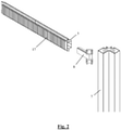
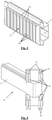
- the slatted wall (1) additionally also comprises a protective corner profile (7) which is attached to bearing sections (5) of one of the walls (2) by means of corner attachment elements (8).
- these bearing sections (5) are of a hollow design, with the cavity (13) being accessible via an end of these bearing sections (5).
- Each corner attachment element (8) comprises a corresponding attachment body (9) which is fittable in this cavity (13).
- the corner attachment element (8) After the attachment body (9) of the corner attachment element (8) has been fitted in the cavity (13) of the corresponding bearing section (5), the corner attachment element (8) is slideable with respect to this bearing section (5) along the length direction of the bearing section (5).
- the shape of the attachment body (9) corresponds to the shape of the cavity (13) to this end.
- Each corner attachment element (8) is furthermore provided with fitting slots (11) which are protected on either side by an elastically displaceable fitting rib (12).
- the protective corner profile (7) is provided with corresponding fitting ribs (10) comprising a widened head (14) which can be click-fitted into the fitting slots (11).
- click-fitting the protective corner profile (7) takes place along a direction (A) at right angles to the rib (4) and at an angle ( ⁇ , ⁇ ') with respect to each of the two walls (2, 3).
- the elastically displaceable fitting ribs (12) of the corner attachment element (8) are provided with an undercut (15) behind which, in the installed position, the widened head (14) of the corresponding fitting rib (10) of the protective corner profile (7) engages.
- the fitting ribs (10) thereof are guided from the corner attachment element (8) to the corresponding fitting slots (11) by guiding surfaces (23) of the fitting ribs (12).
- the widened head (14) of the fitting ribs (10) of the protective corner profile (7) then first pushes the elastically displaceable fitting ribs (12) away, after which these elastic fitting ribs (12) reassume their original position.
- each fitting rib (10) of the protective corner profile (7) is click-fitted between the corresponding elastically displaceable fitting ribs (12) of the corner attachment element (8).
- the undercuts (15) prevent the head (14) from coming out of the fitting slot (11).
- the protective corner profile (7) is then still slideable with respect to the corner attachment element (8) along the length direction of the rib (4).
- the protective corner profile (7) is furthermore provided with protective legs (16) by means of which this protective corner profile (7), in the fitted position, partly overlaps the adjacent slats (6).
- the slats (6) are also provided with a protective leg (21) which is provided in order to be able, in the fitted position, to partly overlap a projecting flange (22) of an adjacent slat (6).
- this protective corner profile (7), in the fitted position will then either overlap this protective leg (21) of an adjacent slat (6), as can be seen in Fig. 6 , or such a projecting flange (22).
Landscapes
- Engineering & Computer Science (AREA)
- Architecture (AREA)
- Civil Engineering (AREA)
- Structural Engineering (AREA)
- Finishing Walls (AREA)
- Details Of Indoor Wiring (AREA)
Claims (13)
- Revêtement mural (1) comprenant deux parois (2, 3) qui se rejoignent à un angle (α) dans une nervure commune (4), chaque paroi comprenant :des sections de support (5), dont une extrémité se termine à la position de la nervure (4) ;des éléments de revêtement mural (6) qui sont fixés aux sections de support (5), revêtant ainsi ces sections de support (5) ; etun profil de protection d'angle(7) afin de former la nervure (4) ; caractérisé en ce que le revêtement mural comprend en outre :des éléments de fixation d'angle (8) qui sont fixés aux sections de support (5), pouvant être déplacés par rapport à ces sections de support (5) dans le sens de la longueur de ces sections de support (5), jusqu'à l'extérieur du côté avant de ces sections de support (5) sur une extrémité et dans lequel chaque élément de fixation d'angle (8) et le profil de protection d'angle (7) sont munis d'éléments de fixation correspondants (10, 11) qui peuvent être mutuellement couplés afin de fixer l'élément de fixation d'angle (8) et le profil de protection d'angle (7) l'un à l'autre ;moyennant que chaque élément de fixation d'angle (8) est fixé à une section de support (5) d'une seule des parois.
- Revêtement mural (1) selon la revendication 1, caractérisé en ce que l'élément de fixation d'angle (8) et le profil de protection d'angle(7) peuvent être mutuellement déplacés dans le sens de la longueur de la nervure (4) dans la position de couplage mutuel.
- Revêtement mural (1) selon l'une des revendications précédentes, caractérisé en ce que la section de support (5) comprend une cavité (13) ayant une ouverture d'accès à ladite extrémité, dans laquelle le corps de fixation (9) de l'élément de fixation d'angle (8) est au moins en partie ajusté afin de fixer l'élément de fixation d'angle (8) à la section de support (5).
- Revêtement mural (1) selon l'une des revendications précédentes, caractérisé en ce que les éléments de fixation (10, 11) sont couplés mutuellement par emboîtement.
- Revêtement mural (1) selon la revendication 4, caractérisé en ce que l'élément de fixation d'angle (8) est muni d'une fente de fixation (11) ou d'une nervure de fixation en tant qu'élément de fixation (11), et en ce que le profil de protection d'angle (7) est muni d'une nervure de fixation (10) ou d'une fente de fixation correspondante en tant qu'élément de fixation (10), dans lequel la nervure de fixation (10) est fixée dans la fente de fixation correspondante (11) par emboîtement.
- Revêtement mural (1) selon l'une des revendications précédentes, caractérisé en ce que les éléments de fixation (10, 11) sont couplés mutuellement au moyen d'une liaison par encliquetage.
- Revêtement mural (1) selon la revendication 6, caractérisé en ce que le profil de protection d'angle (7) comprend une nervure de fixation (10) ayant une tête élargie (14) en tant qu'élément de fixation (10), et en ce que l'élément de fixation d'angle (8) comprend une nervure de fixation correspondante à déplacement élastique (12) qui délimite en partie une fente de fixation (11) en tant qu'élément de fixation (11) afin d'agencer la tête élargie (14) à l'intérieur et qui est munie d'une encoche (15), de sorte que, lorsque la nervure de fixation (10) du profil de protection d'angle (7) est ajusté dans la fente de fixation (11) de l'élément de fixation d'angle (8), cette nervure de fixation à déplacement élastique (12) est éloignée de force au moyen de la tête élargie (14) et revient, de sorte que la tête (14) du profil de protection d'angle (7) vient en prise derrière l'encoche (15) dans la position couplée du profil de protection d'angle(7) et de l'élément de fixation d'angle (8).
- Revêtement mural (1) selon la revendication 7, caractérisé en ce que l'élément de fixation d'angle (8) comprend un élément guide (23) qui est disposé adjacent à la nervure de fixation à déplacement élastique (12) ou fait partie de celle-ci afin de guider la tête élargie (14) de la nervure de fixation (10) depuis le profil de protection d'angle (7) en direction de la fente de fixation (11) pendant le couplage du profil de protection d'angle (7) et de l'élément de fixation d'angle (8).
- Revêtement mural (1) selon la revendication 8, caractérisé en ce que l'élément guide est conçu comme un arc de guidage qui est disposé entre deux nervures de fixation à déplacement élastique (12) qui délimitent en partie des fentes adjacentes de délimitation (11).
- Revêtement mural (1) selon l'une des revendications précédentes, caractérisé en ce que les éléments de fixation (10, 11) sont mutuellement couplés le long d'une direction (A) à un angle (β, β') par rapport à chacune des deux parois (2, 3).
- Revêtement mural (1) selon l'une des revendications précédentes, caractérisé en ce que les éléments de revêtement mural (6) sont conçus sous forme de montants (6) .
- Revêtement mural (1) selon l'une des revendications précédentes, caractérisé en ce que le profil de protection d'angle (7) est muni d'une jambe de protection (16) afin de chevaucher en partie, dans la position fixée, lesdits éléments de revêtement mural (6).
- Revêtement mural (1) selon l'une des revendications précédentes, caractérisé en ce que l'élément de fixation d'angle (8) est constitué de plastique.
Priority Applications (1)
| Application Number | Priority Date | Filing Date | Title |
|---|---|---|---|
| PL18733676T PL3635193T3 (pl) | 2017-05-31 | 2018-05-23 | Okładzina ścienna |
Applications Claiming Priority (2)
| Application Number | Priority Date | Filing Date | Title |
|---|---|---|---|
| BE2017/5391A BE1025257B1 (nl) | 2017-05-31 | 2017-05-31 | Wandbekleding |
| PCT/IB2018/053641 WO2018220481A1 (fr) | 2017-05-31 | 2018-05-23 | Revêtement mural |
Publications (2)
| Publication Number | Publication Date |
|---|---|
| EP3635193A1 EP3635193A1 (fr) | 2020-04-15 |
| EP3635193B1 true EP3635193B1 (fr) | 2022-03-09 |
Family
ID=59014407
Family Applications (1)
| Application Number | Title | Priority Date | Filing Date |
|---|---|---|---|
| EP18733676.3A Active EP3635193B1 (fr) | 2017-05-31 | 2018-05-23 | Revêtement mural |
Country Status (5)
| Country | Link |
|---|---|
| EP (1) | EP3635193B1 (fr) |
| BE (1) | BE1025257B1 (fr) |
| ES (1) | ES2911405T3 (fr) |
| PL (1) | PL3635193T3 (fr) |
| WO (1) | WO2018220481A1 (fr) |
Citations (1)
| Publication number | Priority date | Publication date | Assignee | Title |
|---|---|---|---|---|
| US6634824B2 (en) * | 2001-08-23 | 2003-10-21 | Yu-An Liu | Connective device in a partition screen system |
Family Cites Families (5)
| Publication number | Priority date | Publication date | Assignee | Title |
|---|---|---|---|---|
| FR2121393B2 (fr) * | 1971-01-08 | 1973-11-30 | Prost Georges | |
| DE4418291A1 (de) * | 1994-05-26 | 1995-03-23 | Siegfried Hatzlhoffer | Befestigungssystem zur Montage von Profilbrettern, Paneelen oder Kassetten |
| DE19620134A1 (de) * | 1996-05-18 | 1997-11-20 | Otto Dr Ing Wolf | Fliese zum Verlegen auf einem durch eine Wand oder einen Boden gebildeten Tragkörper und Einrichtung zur Aufnahme und zur Lagefixierung der Fliese |
| DE202006018241U1 (de) * | 2006-12-01 | 2007-07-12 | Hamel, Werner | System von Verblendplatten und Halteelementen zur Verblendung von Baukörpern |
| KR101462789B1 (ko) * | 2013-06-21 | 2014-11-21 | 안계원 | 주택형 이동 조립텐트 |
-
2017
- 2017-05-31 BE BE2017/5391A patent/BE1025257B1/nl not_active IP Right Cessation
-
2018
- 2018-05-23 WO PCT/IB2018/053641 patent/WO2018220481A1/fr not_active Ceased
- 2018-05-23 EP EP18733676.3A patent/EP3635193B1/fr active Active
- 2018-05-23 PL PL18733676T patent/PL3635193T3/pl unknown
- 2018-05-23 ES ES18733676T patent/ES2911405T3/es active Active
Patent Citations (1)
| Publication number | Priority date | Publication date | Assignee | Title |
|---|---|---|---|---|
| US6634824B2 (en) * | 2001-08-23 | 2003-10-21 | Yu-An Liu | Connective device in a partition screen system |
Also Published As
| Publication number | Publication date |
|---|---|
| PL3635193T3 (pl) | 2022-05-23 |
| WO2018220481A1 (fr) | 2018-12-06 |
| BE1025257B1 (nl) | 2019-01-07 |
| BE1025257A1 (nl) | 2019-01-03 |
| ES2911405T3 (es) | 2022-05-19 |
| EP3635193A1 (fr) | 2020-04-15 |
Similar Documents
| Publication | Publication Date | Title |
|---|---|---|
| US8789900B2 (en) | Door for a household appliance | |
| US10072687B2 (en) | Board interlocking structure | |
| CA2793054A1 (fr) | Espaceur ajustable a longueur variable | |
| ITPD20000048U1 (it) | Struttura di gabbia componibile. | |
| JP2009127420A (ja) | 異形材レールシステム | |
| EP3469166B1 (fr) | Revêtement mural | |
| US12054954B2 (en) | Fire-safe wall cladding | |
| US20190186153A1 (en) | Railing system | |
| US20070214738A1 (en) | Extendable drip edge | |
| WO2016009073A1 (fr) | Système de raccordement de panneaux muraux destiné à des unités de construction modulaires | |
| KR20170129103A (ko) | 솔라패널 부착용 장치 | |
| EP3635193B1 (fr) | Revêtement mural | |
| RU2676794C1 (ru) | Архитектурные жалюзи (варианты) | |
| KR200459675Y1 (ko) | 콘센트 고정용 전기박스 | |
| EP2771531B1 (fr) | Trappes d'accès | |
| US8984820B1 (en) | Geometrics window system | |
| AU2024201542B2 (en) | Waterproof Wall Cladding | |
| KR20150133063A (ko) | 다용도 조립식 패널 | |
| KR102421686B1 (ko) | 탈거방지를 위한 조립식 결로방지패드 및 이를 포함하는 창호브라켓 | |
| EP2891434B1 (fr) | Couverture de store et connecteur de couverture de store | |
| JP5264568B2 (ja) | 床下点検口 | |
| JP6851162B2 (ja) | パネル、パネル組立体、及びユニット式ルーム | |
| KR20170105261A (ko) | 건축물 외장패널 | |
| JP6120170B2 (ja) | 戸枠 | |
| JP2017133349A (ja) | 窓額縁および建具 |
Legal Events
| Date | Code | Title | Description |
|---|---|---|---|
| STAA | Information on the status of an ep patent application or granted ep patent |
Free format text: STATUS: UNKNOWN |
|
| STAA | Information on the status of an ep patent application or granted ep patent |
Free format text: STATUS: THE INTERNATIONAL PUBLICATION HAS BEEN MADE |
|
| PUAI | Public reference made under article 153(3) epc to a published international application that has entered the european phase |
Free format text: ORIGINAL CODE: 0009012 |
|
| STAA | Information on the status of an ep patent application or granted ep patent |
Free format text: STATUS: REQUEST FOR EXAMINATION WAS MADE |
|
| 17P | Request for examination filed |
Effective date: 20191211 |
|
| AK | Designated contracting states |
Kind code of ref document: A1 Designated state(s): AL AT BE BG CH CY CZ DE DK EE ES FI FR GB GR HR HU IE IS IT LI LT LU LV MC MK MT NL NO PL PT RO RS SE SI SK SM TR |
|
| AX | Request for extension of the european patent |
Extension state: BA ME |
|
| RAP1 | Party data changed (applicant data changed or rights of an application transferred) |
Owner name: RENSON VENTILATION NV |
|
| DAV | Request for validation of the european patent (deleted) | ||
| DAX | Request for extension of the european patent (deleted) | ||
| STAA | Information on the status of an ep patent application or granted ep patent |
Free format text: STATUS: EXAMINATION IS IN PROGRESS |
|
| 17Q | First examination report despatched |
Effective date: 20210114 |
|
| GRAP | Despatch of communication of intention to grant a patent |
Free format text: ORIGINAL CODE: EPIDOSNIGR1 |
|
| STAA | Information on the status of an ep patent application or granted ep patent |
Free format text: STATUS: GRANT OF PATENT IS INTENDED |
|
| INTG | Intention to grant announced |
Effective date: 20211104 |
|
| GRAS | Grant fee paid |
Free format text: ORIGINAL CODE: EPIDOSNIGR3 |
|
| GRAA | (expected) grant |
Free format text: ORIGINAL CODE: 0009210 |
|
| STAA | Information on the status of an ep patent application or granted ep patent |
Free format text: STATUS: THE PATENT HAS BEEN GRANTED |
|
| AK | Designated contracting states |
Kind code of ref document: B1 Designated state(s): AL AT BE BG CH CY CZ DE DK EE ES FI FR GB GR HR HU IE IS IT LI LT LU LV MC MK MT NL NO PL PT RO RS SE SI SK SM TR |
|
| REG | Reference to a national code |
Ref country code: CH Ref legal event code: EP Ref country code: AT Ref legal event code: REF Ref document number: 1474277 Country of ref document: AT Kind code of ref document: T Effective date: 20220315 |
|
| REG | Reference to a national code |
Ref country code: IE Ref legal event code: FG4D |
|
| REG | Reference to a national code |
Ref country code: DE Ref legal event code: R096 Ref document number: 602018031977 Country of ref document: DE |
|
| REG | Reference to a national code |
Ref country code: NL Ref legal event code: FP |
|
| REG | Reference to a national code |
Ref country code: ES Ref legal event code: FG2A Ref document number: 2911405 Country of ref document: ES Kind code of ref document: T3 Effective date: 20220519 |
|
| REG | Reference to a national code |
Ref country code: LT Ref legal event code: MG9D |
|
| PG25 | Lapsed in a contracting state [announced via postgrant information from national office to epo] |
Ref country code: SE Free format text: LAPSE BECAUSE OF FAILURE TO SUBMIT A TRANSLATION OF THE DESCRIPTION OR TO PAY THE FEE WITHIN THE PRESCRIBED TIME-LIMIT Effective date: 20220309 Ref country code: RS Free format text: LAPSE BECAUSE OF FAILURE TO SUBMIT A TRANSLATION OF THE DESCRIPTION OR TO PAY THE FEE WITHIN THE PRESCRIBED TIME-LIMIT Effective date: 20220309 Ref country code: NO Free format text: LAPSE BECAUSE OF FAILURE TO SUBMIT A TRANSLATION OF THE DESCRIPTION OR TO PAY THE FEE WITHIN THE PRESCRIBED TIME-LIMIT Effective date: 20220609 Ref country code: LT Free format text: LAPSE BECAUSE OF FAILURE TO SUBMIT A TRANSLATION OF THE DESCRIPTION OR TO PAY THE FEE WITHIN THE PRESCRIBED TIME-LIMIT Effective date: 20220309 Ref country code: HR Free format text: LAPSE BECAUSE OF FAILURE TO SUBMIT A TRANSLATION OF THE DESCRIPTION OR TO PAY THE FEE WITHIN THE PRESCRIBED TIME-LIMIT Effective date: 20220309 Ref country code: BG Free format text: LAPSE BECAUSE OF FAILURE TO SUBMIT A TRANSLATION OF THE DESCRIPTION OR TO PAY THE FEE WITHIN THE PRESCRIBED TIME-LIMIT Effective date: 20220609 |
|
| PG25 | Lapsed in a contracting state [announced via postgrant information from national office to epo] |
Ref country code: LV Free format text: LAPSE BECAUSE OF FAILURE TO SUBMIT A TRANSLATION OF THE DESCRIPTION OR TO PAY THE FEE WITHIN THE PRESCRIBED TIME-LIMIT Effective date: 20220309 Ref country code: GR Free format text: LAPSE BECAUSE OF FAILURE TO SUBMIT A TRANSLATION OF THE DESCRIPTION OR TO PAY THE FEE WITHIN THE PRESCRIBED TIME-LIMIT Effective date: 20220610 Ref country code: FI Free format text: LAPSE BECAUSE OF FAILURE TO SUBMIT A TRANSLATION OF THE DESCRIPTION OR TO PAY THE FEE WITHIN THE PRESCRIBED TIME-LIMIT Effective date: 20220309 |
|
| PG25 | Lapsed in a contracting state [announced via postgrant information from national office to epo] |
Ref country code: SM Free format text: LAPSE BECAUSE OF FAILURE TO SUBMIT A TRANSLATION OF THE DESCRIPTION OR TO PAY THE FEE WITHIN THE PRESCRIBED TIME-LIMIT Effective date: 20220309 Ref country code: SK Free format text: LAPSE BECAUSE OF FAILURE TO SUBMIT A TRANSLATION OF THE DESCRIPTION OR TO PAY THE FEE WITHIN THE PRESCRIBED TIME-LIMIT Effective date: 20220309 Ref country code: RO Free format text: LAPSE BECAUSE OF FAILURE TO SUBMIT A TRANSLATION OF THE DESCRIPTION OR TO PAY THE FEE WITHIN THE PRESCRIBED TIME-LIMIT Effective date: 20220309 Ref country code: PT Free format text: LAPSE BECAUSE OF FAILURE TO SUBMIT A TRANSLATION OF THE DESCRIPTION OR TO PAY THE FEE WITHIN THE PRESCRIBED TIME-LIMIT Effective date: 20220711 Ref country code: EE Free format text: LAPSE BECAUSE OF FAILURE TO SUBMIT A TRANSLATION OF THE DESCRIPTION OR TO PAY THE FEE WITHIN THE PRESCRIBED TIME-LIMIT Effective date: 20220309 |
|
| PG25 | Lapsed in a contracting state [announced via postgrant information from national office to epo] |
Ref country code: IS Free format text: LAPSE BECAUSE OF FAILURE TO SUBMIT A TRANSLATION OF THE DESCRIPTION OR TO PAY THE FEE WITHIN THE PRESCRIBED TIME-LIMIT Effective date: 20220709 Ref country code: AL Free format text: LAPSE BECAUSE OF FAILURE TO SUBMIT A TRANSLATION OF THE DESCRIPTION OR TO PAY THE FEE WITHIN THE PRESCRIBED TIME-LIMIT Effective date: 20220309 |
|
| REG | Reference to a national code |
Ref country code: DE Ref legal event code: R097 Ref document number: 602018031977 Country of ref document: DE |
|
| PLBE | No opposition filed within time limit |
Free format text: ORIGINAL CODE: 0009261 |
|
| STAA | Information on the status of an ep patent application or granted ep patent |
Free format text: STATUS: NO OPPOSITION FILED WITHIN TIME LIMIT |
|
| PG25 | Lapsed in a contracting state [announced via postgrant information from national office to epo] |
Ref country code: MC Free format text: LAPSE BECAUSE OF FAILURE TO SUBMIT A TRANSLATION OF THE DESCRIPTION OR TO PAY THE FEE WITHIN THE PRESCRIBED TIME-LIMIT Effective date: 20220309 Ref country code: DK Free format text: LAPSE BECAUSE OF FAILURE TO SUBMIT A TRANSLATION OF THE DESCRIPTION OR TO PAY THE FEE WITHIN THE PRESCRIBED TIME-LIMIT Effective date: 20220309 |
|
| 26N | No opposition filed |
Effective date: 20221212 |
|
| PG25 | Lapsed in a contracting state [announced via postgrant information from national office to epo] |
Ref country code: SI Free format text: LAPSE BECAUSE OF FAILURE TO SUBMIT A TRANSLATION OF THE DESCRIPTION OR TO PAY THE FEE WITHIN THE PRESCRIBED TIME-LIMIT Effective date: 20220309 |
|
| PG25 | Lapsed in a contracting state [announced via postgrant information from national office to epo] |
Ref country code: IE Free format text: LAPSE BECAUSE OF NON-PAYMENT OF DUE FEES Effective date: 20220523 |
|
| P01 | Opt-out of the competence of the unified patent court (upc) registered |
Effective date: 20230327 |
|
| PG25 | Lapsed in a contracting state [announced via postgrant information from national office to epo] |
Ref country code: MK Free format text: LAPSE BECAUSE OF FAILURE TO SUBMIT A TRANSLATION OF THE DESCRIPTION OR TO PAY THE FEE WITHIN THE PRESCRIBED TIME-LIMIT Effective date: 20220309 Ref country code: CY Free format text: LAPSE BECAUSE OF FAILURE TO SUBMIT A TRANSLATION OF THE DESCRIPTION OR TO PAY THE FEE WITHIN THE PRESCRIBED TIME-LIMIT Effective date: 20220309 |
|
| PG25 | Lapsed in a contracting state [announced via postgrant information from national office to epo] |
Ref country code: HU Free format text: LAPSE BECAUSE OF FAILURE TO SUBMIT A TRANSLATION OF THE DESCRIPTION OR TO PAY THE FEE WITHIN THE PRESCRIBED TIME-LIMIT; INVALID AB INITIO Effective date: 20180523 |
|
| REG | Reference to a national code |
Ref country code: LU Ref legal event code: HC Owner name: RENSON NV; BE Free format text: FORMER OWNER: RENSON VENTILATION NV Effective date: 20240830 |
|
| PG25 | Lapsed in a contracting state [announced via postgrant information from national office to epo] |
Ref country code: MT Free format text: LAPSE BECAUSE OF FAILURE TO SUBMIT A TRANSLATION OF THE DESCRIPTION OR TO PAY THE FEE WITHIN THE PRESCRIBED TIME-LIMIT Effective date: 20220309 |
|
| REG | Reference to a national code |
Ref country code: NL Ref legal event code: HC Owner name: RENSON NV; BE Free format text: DETAILS ASSIGNMENT: CHANGE OF OWNER(S), CHANGE OF OWNER(S) NAME; FORMER OWNER NAME: RENSON VENTILATION NV Effective date: 20241023 |
|
| REG | Reference to a national code |
Ref country code: BE Ref legal event code: HC Owner name: RENSON NV; BE Free format text: DETAILS ASSIGNMENT: CHANGE OF OWNER(S), CHANGE OF OWNER(S) NAME; FORMER OWNER NAME: RENSON VENTILATION NV Effective date: 20240909 |
|
| REG | Reference to a national code |
Ref country code: AT Ref legal event code: HC Ref document number: 1474277 Country of ref document: AT Kind code of ref document: T Owner name: RENSON NV, BE Effective date: 20241205 |
|
| REG | Reference to a national code |
Ref country code: ES Ref legal event code: PC2A Owner name: RENSON NV Effective date: 20250327 |
|
| PGFP | Annual fee paid to national office [announced via postgrant information from national office to epo] |
Ref country code: NL Payment date: 20250521 Year of fee payment: 8 |
|
| PGFP | Annual fee paid to national office [announced via postgrant information from national office to epo] |
Ref country code: PL Payment date: 20250418 Year of fee payment: 8 Ref country code: DE Payment date: 20250521 Year of fee payment: 8 |
|
| PGFP | Annual fee paid to national office [announced via postgrant information from national office to epo] |
Ref country code: GB Payment date: 20250527 Year of fee payment: 8 |
|
| PGFP | Annual fee paid to national office [announced via postgrant information from national office to epo] |
Ref country code: LU Payment date: 20250521 Year of fee payment: 8 Ref country code: BE Payment date: 20250521 Year of fee payment: 8 Ref country code: IT Payment date: 20250527 Year of fee payment: 8 |
|
| PGFP | Annual fee paid to national office [announced via postgrant information from national office to epo] |
Ref country code: FR Payment date: 20250528 Year of fee payment: 8 |
|
| PGFP | Annual fee paid to national office [announced via postgrant information from national office to epo] |
Ref country code: CH Payment date: 20250601 Year of fee payment: 8 |
|
| PGFP | Annual fee paid to national office [announced via postgrant information from national office to epo] |
Ref country code: AT Payment date: 20250522 Year of fee payment: 8 |
|
| PGFP | Annual fee paid to national office [announced via postgrant information from national office to epo] |
Ref country code: CZ Payment date: 20250515 Year of fee payment: 8 |
|
| REG | Reference to a national code |
Ref country code: DE Ref legal event code: R081 Ref document number: 602018031977 Country of ref document: DE Owner name: RENSON NV, BE Free format text: FORMER OWNER: RENSON VENTILATION NV, WAREGEM, BE |
|
| PGFP | Annual fee paid to national office [announced via postgrant information from national office to epo] |
Ref country code: ES Payment date: 20250630 Year of fee payment: 8 |
|
| PG25 | Lapsed in a contracting state [announced via postgrant information from national office to epo] |
Ref country code: TR Free format text: LAPSE BECAUSE OF FAILURE TO SUBMIT A TRANSLATION OF THE DESCRIPTION OR TO PAY THE FEE WITHIN THE PRESCRIBED TIME-LIMIT Effective date: 20220309 |