EP3635211B1 - Support d'échelle - Google Patents
Support d'échelle Download PDFInfo
- Publication number
- EP3635211B1 EP3635211B1 EP18732427.2A EP18732427A EP3635211B1 EP 3635211 B1 EP3635211 B1 EP 3635211B1 EP 18732427 A EP18732427 A EP 18732427A EP 3635211 B1 EP3635211 B1 EP 3635211B1
- Authority
- EP
- European Patent Office
- Prior art keywords
- wall
- ladder
- base
- side walls
- dimensional space
- Prior art date
- Legal status (The legal status is an assumption and is not a legal conclusion. Google has not performed a legal analysis and makes no representation as to the accuracy of the status listed.)
- Active
Links
Images




Classifications
-
- E—FIXED CONSTRUCTIONS
- E06—DOORS, WINDOWS, SHUTTERS, OR ROLLER BLINDS IN GENERAL; LADDERS
- E06C—LADDERS
- E06C7/00—Component parts, supporting parts, or accessories
- E06C7/42—Ladder feet; Supports therefor
- E06C7/426—Height adjustable supports for receiving both ladder feet
-
- E—FIXED CONSTRUCTIONS
- E06—DOORS, WINDOWS, SHUTTERS, OR ROLLER BLINDS IN GENERAL; LADDERS
- E06C—LADDERS
- E06C5/00—Ladders characterised by being mounted on undercarriages or vehicles Securing ladders on vehicles
- E06C5/32—Accessories, e.g. brakes on ladders
- E06C5/36—Safety devices against slipping or falling of ladders; Safety devices against overloading ladders
-
- E—FIXED CONSTRUCTIONS
- E06—DOORS, WINDOWS, SHUTTERS, OR ROLLER BLINDS IN GENERAL; LADDERS
- E06C—LADDERS
- E06C7/00—Component parts, supporting parts, or accessories
- E06C7/003—Indicating devices, e.g. user warnings or inclinators
-
- E—FIXED CONSTRUCTIONS
- E06—DOORS, WINDOWS, SHUTTERS, OR ROLLER BLINDS IN GENERAL; LADDERS
- E06C—LADDERS
- E06C7/00—Component parts, supporting parts, or accessories
- E06C7/42—Ladder feet; Supports therefor
- E06C7/46—Non-skid equipment
Definitions
- the present invention relates to a ladder stabiliser and, particularly, but not exclusively, to a ladder stabiliser that obviates the existing requirement for a leaning ladder to be physically secured to a building and/or "footed" near the ground by a second person.
- Guidance issued by the HSE states that ladders must be prevented from slipping during use by adopting one of the following options (presented in diminishing order of preference): (i) tying both stiles of the ladder to secure anchor points; (ii) using a ladder stability device; (iii) securely wedging the stiles of the ladder against a wall; and finally (iv) only if none of the foregoing is possible, "footing" of the ladder by a second person.
- option (i) above requires appropriate anchor points to be available or invasively installed, e.g. on a building facade, and so is often not desirable or practicable, particularly if - as is often the case - the job at hand requires regular movement of a ladder to a new position.
- option (ii) many existing stability devices provide only limited protection (as discussed further below) and require a degree of diligence on the part of the user for safe usage.
- Option (iii) is rarely available and, even when it is, it significantly constrains the placement of the feet of a ladder and its angle of inclination. For those reasons, the most commonly adopted option is footing of the ladder by a second person.
- human factors such as the tendency for a person to become distracted or complacent mean that this is an unreliable method of ensuring the safety of a person working at height.
- the present invention therefore seeks to provide an improved ladder stabiliser which addresses, or at least ameliorates, one or more of the aforementioned disadvantages by ensuring that a single person can safely use a ladder in all circumstances. In preferred embodiments, this is achieved whilst also satisfying existing legislative safety requirements.
- US6053284A discloses a support frame for a ladder.
- US8042651B1 discloses a ladder support device.
- US8393586B1 discloses a hitch mountable ladder support.
- US20020166723A1 discloses an adapter for connection between a vehicle and a ladder.
- a ladder stabiliser according to claim 1.
- an increased height of said at least one wall provides additional support to a ladder and reduces or eliminates unwanted movement of its lowermost distal ends.
- said at least one wall extends to a height above the base of at least 25 cm, this being the generally expected minimum spacing of ladder rungs.
- the first rung on a ladder will usually be located a distance of less than 25cm from the ladder feet and so this wall height will, in the vast majority of cases, exceed the height of the lowermost ladder rung.
- said first three-dimensional space is defined, at least in part, by substantially planar spaced apart side walls each extending upwards from the base.
- Said first three-dimensional space is defined, at least in part, by a substantially planar first wall extending upwards from the base.
- the first wall extends between the spaced apart side walls.
- the first wall is inclined at an angle of inclination with respect to the base for providing support, in use, to the rear surfaces of ladder stiles located within the first three-dimensional space defined by the base, the first wall, and the side walls.
- the angle of inclination of the first wall relative to the base is between 75 degrees and 77 degrees.
- the angle of inclination of the first wall relative to the base is 75.96 degrees.
- an angle of inclination of 75.96 degrees corresponds to the optimum "1 in 4" gradient rule whereby for every four units of height to be climbed, the base of the ladder moves one unit out.
- a pair of laterally adjustable clamps are arranged within the first three-dimensional space for selectively engaging, in use, respective outer lateral side surfaces of ladder stiles.
- the laterally adjustable clamps are attached to the respective opposing side walls of the first three-dimensional space.
- Said first three-dimensional space is defined, at least in part, by a substantially planar second wall extending upwards from the base.
- the second wall is spaced from the first wall and extends between the spaced apart side walls.
- At least one of the respective side walls, the first wall and the second wall extends to a height above the base which is greater, in use, than that of the lowermost rung of an inclined ladder.
- the presence of the second wall will resist: (i) slippage of both ladder stiles in a direction away from the inclined first wall; and (ii) forward movement of a single ladder stile in a twisting movement away from general plane of the inclined first wall.
- the second wall has a hinged connection with the base and is moveable between an open and closed positions.
- a lock is provided for selectively securing the second wall in the closed position.
- the open position of the second wall facilitates movement of a ladder into and out of the first three-dimensional space.
- the second wall When in the closed position, the second wall is inclined relative to the base, its angle of inclination being substantially equal to that of the first wall.
- the first and second walls and the side walls together delineate a rectangular shape in cross-section through a plane parallel to the base.
- a central recessed portion is formed in the first wall.
- the central recessed portion is provided with a base, opposing side walls and a rear wall.
- a central cut-out portion is provided on the second wall to generally coincide with the central recessed portion formed in the first wall.
- the two lateral inclined faces of the first wall either side of the central recessed portion are arranged to coincide with the position of the spaced stiles of a ladder when it is located within the first three-dimensional space; and the central recessed portion is dimensioned to accommodate the part of a user's foot which, during use, extends beyond the lowermost rung of a ladder.
- a substantially planar third wall extends upwards from the base.
- the third wall is spaced from the first wall and extends between the spaced apart side walls.
- a second open-topped three-dimensional space is defined by the spaced apart first and third walls, and the spaced apart side walls.
- At least one removable ballast weight is receivable within the second three-dimensional space.
- the cumulative weight of the ballast within the second three-dimensional space will be sufficient to anchor the ladder stabiliser and its associated ladder.
- the particular weight required to do so may vary dependent on various factors including the height of the ladder, the weight of the user and any materials being carried.
- the cumulative overall ballast weight may be distributed between multiple ballasts of lesser individual weight.
- An optimum weight for each individual ballast will be no more than 25kg which is generally accepted as being the maximum safe weight to be carried manually by a male.
- height-adjustable feet are connected to the base and/or side walls for levelling the ladder stabiliser before use.
- the height-adjustable feet are located at fixed positions proximate each corner of the base and/or side walls.
- the height-adjustable feet are provided on struts which are pivotably deployable away from each side wall.
- a fourth wall is spaced from the third wall and extends between the spaced apart side walls to define a third open-topped three-dimensional space.
- the third open-topped three-dimensional space may be used as a storage space.
- the third open-topped three-dimensional space may be used to store collapsible fluorescent warning cones for placement around the ladder stabiliser during use.
- At least two spirit levels are provided on at least two of the respective side walls, the first wall, the second wall, the third wall, and the fourth wall for indicating the inclination of the ladder stabiliser in two perpendicular directions.
- drainage holes are provided in the base.
- graspable handles are formed in, or attached to, at least the side walls to facilitate lifting and manoeuvring of the ladder stabiliser.
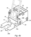
- the ladder stabiliser of the present invention takes the form of a box-like structure 10 comprising: a planar, rectangular base 12 (see Figs. 4a , 4b ) having front, rear, and opposite side peripheral edges 12a-d; two planar side walls 14a, 14b extending vertically from the opposite side peripheral edges 12c, 12d of the base 12; a first planar wall 16 extending upwards from the base 12 at an inclined angle, and extending between the side walls 14a, 14b at a position proximate, but spaced from the front peripheral edge 12a; a second planar wall 18 pivotably attached to the base 12 at its front peripheral edge 12a, and extending between the side walls 14a, 14b; a third planar wall 20 extending vertically from the base 12, and extending between the side walls 14a, 14b at a position proximate, but spaced from and parallel to the rear peripheral edge 12b; and a fourth planar wall 22 extending vertically from the base 12 at its rear peripheral edge
- the second wall 18 is pivotable between a fully open position (see Fig. 4a ) in which it extends substantially parallel to the base 12; and a fully closed position (see Fig. 2 ) in which it extends at an inclined angle which is substantially equal to that of the first wall 16.
- a pair of locks 19 is provided for locking the second wall 18 in the closed position.
- a first open-topped three-dimensional space 24 is defined between the internal surfaces of: the base 12, the first and second inclined walls 16, 18, and the vertical side wall portions 14a, 14b.
- the first and second walls 16, 18, and the side walls 14a, 14b each extend to a vertical height above the base 12. In a preferred embodiment the vertical height is at least 25 cm. It will be appreciated that this height will, in the vast majority of cases, be greater than the height of the first rung of a standard ladder 100 (shown in phantom lines) when arranged, in use, at its optimal angle of inclination.
- the first wall 16 is inclined at an angle of inclination relative to the base 12 which accords with the "1 in 4" gradient rule governing the optimal position for safe ladder use.
- the first wall 16 is provided with a central recess 26 which causes its surface to adopt a general U-shape.
- the central recess 26 is provided with a base 26a, opposing side walls 26b, and a rear wall 26c. Inclined surface portions 16a, 16b are located at either side of the central recess 26.
- a central cut-out portion 28 is provided in the second wall 18, the side walls of which generally coincide and align with those of the central recess 26 formed in the first wall 16.
- the lowermost edge 28a of the central cut-out portion 28 may be arranged to be marginally lower than the base 26a of the central recess 26 within the first wall 16 to provide a degree of clearance for a user's foot as it is placed on, and removed from, the lowermost rung during use of the ladder 100.
- a pair of laterally adjustable clamps 30 are attached to the opposing side wall portions 14a, 14b within the first three-dimensional space 24.
- a detachable and adjustable bracing member 19 is provided within the first open-topped three-dimensional space 24 proximate the base 12.
- the bracing member 19 is generally T-shaped to thereby match the outline shape of the lower part of the pivotable wall 18; and is inclined to match the angle of inclination of the first wall 16 and the pivotable wall 18.
- the bracing member 19 is securable to the inclined first wall 16.
- the spacing of the bracing member 19 from the inclined first wall 16 may be adjusted by, for example, screw threads (not shown) which extend through apertures (not shown) provided in the inclined first wall 16 and fastened behind it with wing nuts (not shown).
- a second open-topped three-dimensional space 32 is defined between the internal surfaces of: the base 12, the first inclined wall 16, the third vertical wall 20, and vertical side wall portions 14a, 14b.
- a third open-topped three-dimensional space 34 is defined between the internal surfaces of: the base 12, the third and fourth vertical walls 20, 22, and vertical side wall portions 14a, 14b.
- Figs 1 to 4b there is provided four height-adjustable feet 36 proximate each lower corner of the box-like structure 10.
- the height-adjustable feet 36 are each attached to a side wall 14a, 14b at a position above its lowermost edge such that they may be vertically retracted and extended above and below the height of the base 12.
- the four height-adjustable feet 136 are attached to elongate triangular struts 138 which are pivotably deployable between: (i) a collapsed/folded position (see Fig. 5a ) whereby they are arranged to overlap and lie substantially parallel to their respective side walls 14a, 14b; and (ii) an extended position (see Fig. 5b ) whereby they are pivoted away from their respective side walls 14a, 14b.
- the ladder stabiliser 10 is positioned proximate a working site in accordance with the aforementioned "1 in 4" rule.
- ballast weights 50 are introduced into the second open-topped three-dimensional space 32 to anchor the ladder stabiliser 10 in position.
- the user may then view the spirit levels provided at the upper edges of the side walls 14a, 14b and the third vertical wall 20 to determine whether the ladder stabiliser 10 is level on the ground. If not, appropriate adjustments are made to the height-adjustable feet 36 to level the ladder stabiliser 10.
- the triangular struts 138 are first deployed by pivoting them away from the respective side walls 14a, 14b before effecting any adjustments via the height-adjustable feet 136.
- a ladder 100 is positioned horizontally with its feet placed against, or proximate to, the first wall 16.
- the ladder 100 is then raised from its opposite end such that the lowermost ends of its stiles lie proximate to, or rest against, the inclined first wall 16; and the uppermost ends of its stiles lie against a supporting surface, e.g. a building wall.
- the user should verify that the ladder stabiliser remains secure and level, and that the "1 in 4" spacing rule is being satisfied. If not, any necessary adjustments to the ladder length and/or positioning or levelling of the ladder stabiliser 10 can be made.
- the second wall 18 is pivoted to its closed position and the locks 19 are re-engaged.
- the lowermost end of the ladder 100 is thereby enclosed within the first open-topped three-dimensional space 24 with its lowermost rung extending across the cut-out portion 28 formed within the second wall 18.
- the ladder 100 may now be used safe in the knowledge that the first, second and side walls 16, 18, 14a, 14b, in combination with the clamps 30, will prevent the full range of unwanted ladder movements associated with "high fall” accidents, i.e. including lateral slippage of a ladder at its upper contact point, and flipping or pivoting of a ladder at its upper end each tend to cause one foot to disengage with the ground.
- the bracing member 19 may, if necessary, be attached and moved in the direction of the inclined first wall 16 to take up any free space between the pivotable wall 18 and the front surfaces of the ladder stiles. Once secured in place, the bracing member 19 provides additional support against unwanted ladder movement that may otherwise arise when, for example, smaller sized ladders 100 are used.
- the ladder stabiliser of the present invention is therefore entirely universal and suitable for use in any industry sectors and countries, irrespective of ladder types and dimensions.
- a user may, by virtue of the central recess 26 and central cut-out portion 28, place his/her foot onto the lowermost ladder rung within the first open-topped three-dimensional space 24 and proceed to climb the ladder.
- the rear surfaces of the ladder stiles are supported by the two lateral inclined portions of the first wall 16; the outside surfaces of the ladder stiles are supported by clamps 30; and significant movement of the ladder away from a supporting surface (such as a building wall) is prevented by the second wall 18. Accordingly, unwanted movement of the ladder is prevented, or at least significantly inhibited, in all directions.
- Graspable handles may be attached to or - as shown in the figures - formed in the side walls 14a, 14b to facilitate lifting and manoeuvring of the ladder stabiliser.
- suitable sized apertures may be formed proximate the lower corners of the first and second walls 16, 18 and the side walls 14a, 14b, as illustrated in the figures. This will ensure that the ladder stabiliser 10 is able to accept different foot structures.
- the ladder stabiliser 10 may be provided with a set of spacers (not shown) which can be introduced into the first open-topped three-dimensional space 24 to fill any gaps in front of and/or behind the stiles. This will ensure that the ladder stabiliser 10 is able to secure all ladders against unwanted movement in a direction perpendicular to the plane of the first wall 16 irrespective of stile thickness.
- the spacers may be stored inside the third open-topped three-dimensional space 34 when not in use.
- a strap and buckle arrangement is attached to the first wall 16 proximate the likely position of the lowermost rung of the ladder 100. This may be used to secure the lowermost rung and prevent it from "kicking up” should it become top heavy as it is raised into position against a supporting surface.
- full opening of the second wall may be inhibited by the presence of the locks 19 on the outside of the second wall 18. This may impede the process of positioning a ladder 100 into the ladder stabiliser 10. Accordingly, in addition to the height adjustable feet 36, 136 shown in the figures, further fixed feet (not shown) may be provided on the underside of the base 12 for the purpose of raising the base above the ground by a distance which is at least equal to the depth distance of the locks 19. This will ensure that the second wall 18 can always be opened to be at least parallel with the base 12.
Landscapes
- Engineering & Computer Science (AREA)
- Mechanical Engineering (AREA)
- Ladders (AREA)
Claims (14)
- Stabilisateur d'échelle comprenant :(i) une base (12) pour supporter, en utilisation, les deux pieds d'une échelle ; et(ii) au moins une première (16) et une deuxième (18) parois sensiblement planes s'étendant vers le haut à partir de la base, et définissant avec la base un premier espace tridimensionnel à sommet ouvert (24) pour recevoir et renfermer au moins partiellement les extrémités distales inférieures d'une échelle ;dans lequel au moins une partie desdites au moins deux parois s'étend jusqu'à une hauteur au-dessus de la base qui, en utilisation, est égale ou supérieure à celle du barreau le plus bas d'une échelle inclinée ;
caractérisé en ce que la deuxième paroi sensiblement plane présente une liaison articulée avec la base et est mobile entre des positions ouverte et fermée. - Stabilisateur d'échelle selon la revendication 1, dans lequel ledit premier espace tridimensionnel est défini, au moins en partie, par des parois latérales espacées sensiblement planes (14a, 14b) s'étendant chacune vers le haut à partir de la base.
- Stabilisateur d'échelle selon la revendication 1, dans lequel la première paroi s'étend entre des parois latérales espacées sensiblement planes (14a, 14b) s'étendant chacune vers le haut à partir de la base.
- Stabilisateur d'échelle selon la revendication 3, dans lequel la première paroi est inclinée selon un angle d'inclinaison par rapport à la base pour fournir un support, en utilisation, aux surfaces arrière de montants d'échelle situés à l'intérieur du premier espace tridimensionnel défini par la base, la première paroi et/ou les parois latérales.
- Stabilisateur d'échelle selon la revendication 4, dans lequel l'angle d'inclinaison de la première paroi par rapport à la base est compris entre 75 degrés et 77 degrés.
- Stabilisateur d'échelle selon la revendication 5, dans lequel l'angle d'inclinaison de la première paroi par rapport à la base est de 75,96 degrés.
- Stabilisateur d'échelle selon la revendication 1, dans lequel une paire d'agrafes réglables latéralement (30) sont agencées à l'intérieur du premier espace tridimensionnel pour venir en prise sélectivement, en utilisation, avec des surfaces latérales externes respectives de montants d'échelle, et, facultativement, dans lequel, lorsqu'il dépend de la revendication 2, les agrafes réglables latéralement sont fixées à des parois latérales opposées du premier espace tridimensionnel.
- Stabilisateur d'échelle selon la revendication 1 : dans lequel la deuxième paroi est espacée de la première paroi et s'étend entre les parois latérales espacées ; et/ou dans lequel, lorsqu'il dépend de la revendication 2, au moins l'une des parois latérales respectives s'étend jusqu'à une hauteur au-dessus de la base qui est supérieure, en utilisation, à celle du barreau le plus bas d'une échelle inclinée.
- Stabilisateur d'échelle selon la revendication 1 ou 8, dans lequel un verrou (19) est prévu pour immobiliser sélectivement la deuxième paroi dans la position fermée.
- Stabilisateur d'échelle selon l'une quelconque des revendications 1 à 9, dans lequel une partie évidée centrale (26) est formée dans la première paroi, et, facultativement dans lequel la partie évidée centrale est pourvue d'une base, de parois latérales opposées et d'une paroi arrière ; et/ou dans lequel une partie découpée centrale est prévue sur la deuxième paroi pour coïncider de manière générale avec la partie évidée centrale formée dans la première paroi.
- Stabilisateur d'échelle selon l'une quelconque des revendications 1 à 10, dans lequel une troisième paroi sensiblement plane (20) s'étend vers le haut à partir de la base, et, facultativement dans lequel la troisième paroi est espacée de la première paroi et s'étend entre les parois latérales espacées ; et/ou dans lequel un deuxième espace tridimensionnel à sommet ouvert (32) est défini par les première et troisième parois espacées, et les parois latérales espacées, et, facultativement dans lequel au moins un poids de lestage amovible peut être reçu à l'intérieur du deuxième espace tridimensionnel.
- Stabilisateur d'échelle selon l'une quelconque des revendications 2 à 11, dans lequel des pieds réglables en hauteur (36) sont reliés à la base et/ou aux parois latérales pour mettre à niveau le stabilisateur d'échelle avant utilisation, et, facultativement dans lequel les pieds réglables en hauteur sont situés à des positions fixes à proximité de chaque coin de la base et/ou des parois latérales ; ou dans lequel les pieds réglables en hauteur sont prévus sur des entretoises (138) qui peuvent être déployées de manière pivotante à l'écart de chaque paroi latérale.
- Stabilisateur d'échelle selon la revendication 11 ou 12, dans lequel une quatrième paroi (22) est espacée de la troisième paroi et s'étend entre les parois latérales espacées pour définir un troisième espace tridimensionnel à sommet ouvert, et, facultativement dans lequel au moins deux niveaux à bulle sont prévus sur au moins deux des parois latérales respectives, la première paroi, la deuxième paroi, la troisième paroi et la quatrième paroi, pour indiquer l'inclinaison du stabilisateur d'échelle dans deux directions perpendiculaires.
- Stabilisateur d'échelle selon une quelconque revendication précédente, dans lequel des trous de drainage sont prévus dans la base ; et/ou dans lequel, lorsqu'il dépend de la revendication 2, des poignées pouvant être saisies sont formées dans, ou fixées à, au moins les parois latérales pour faciliter un levage et une manœuvre du stabilisateur d'échelle.
Applications Claiming Priority (2)
| Application Number | Priority Date | Filing Date | Title |
|---|---|---|---|
| GBGB1709044.0A GB201709044D0 (en) | 2017-06-07 | 2017-06-07 | Ladder stabiliser |
| PCT/GB2018/051549 WO2018224832A1 (fr) | 2017-06-07 | 2018-06-06 | Support d'échelle |
Publications (2)
| Publication Number | Publication Date |
|---|---|
| EP3635211A1 EP3635211A1 (fr) | 2020-04-15 |
| EP3635211B1 true EP3635211B1 (fr) | 2021-11-10 |
Family
ID=59349923
Family Applications (1)
| Application Number | Title | Priority Date | Filing Date |
|---|---|---|---|
| EP18732427.2A Active EP3635211B1 (fr) | 2017-06-07 | 2018-06-06 | Support d'échelle |
Country Status (7)
| Country | Link |
|---|---|
| US (1) | US11499371B2 (fr) |
| EP (1) | EP3635211B1 (fr) |
| AU (1) | AU2018280960B2 (fr) |
| CA (1) | CA3065448A1 (fr) |
| ES (1) | ES2905886T3 (fr) |
| GB (2) | GB201709044D0 (fr) |
| WO (1) | WO2018224832A1 (fr) |
Families Citing this family (3)
| Publication number | Priority date | Publication date | Assignee | Title |
|---|---|---|---|---|
| US11814898B2 (en) * | 2021-10-25 | 2023-11-14 | Joseph Emanuel Falzon | Relation to ladder stabilisation |
| US20240059257A1 (en) * | 2022-08-16 | 2024-02-22 | Sargento Foods Inc. | Cart For Cleaning Trailer Outer Surfaces |
| JP2025170925A (ja) * | 2024-05-08 | 2025-11-20 | 有限会社高橋土木 | 梯子固定装置 |
Family Cites Families (20)
| Publication number | Priority date | Publication date | Assignee | Title |
|---|---|---|---|---|
| US4679652A (en) * | 1986-03-17 | 1987-07-14 | Cervantes Sr Ramiro E | Automatically adjustable ladder support |
| US4846305A (en) * | 1988-11-28 | 1989-07-11 | Kupfert Bernard J | Apparatus for rotatably positioning a ladder within a stairway |
| GB2286621A (en) | 1994-02-10 | 1995-08-23 | Peter Anthony Gerard Mccolgan | Ladder support |
| US6053284A (en) * | 1997-02-18 | 2000-04-25 | Fountain; John W. | Support frame for a ladder |
| US6044929A (en) * | 1999-01-27 | 2000-04-04 | Wishner; David Matthew | Ladder leveling device |
| US6378656B1 (en) * | 1999-11-09 | 2002-04-30 | Thomas Paul Kohler | Ladder leveler |
| US6745869B2 (en) * | 2001-01-22 | 2004-06-08 | Roofmates, Incorporated | Roofmates™ roofing accessories |
| US20080105489A1 (en) * | 2001-01-22 | 2008-05-08 | Robert Garrett | Roofmates gablemaster ladder support |
| US6547036B1 (en) * | 2001-04-10 | 2003-04-15 | Boyce N. Carter | Ladder leg support apparatus |
| US20020166723A1 (en) * | 2001-05-09 | 2002-11-14 | Carol McKee | Adapter for connection between vehicle and ladder |
| GB2449728A (en) * | 2006-08-29 | 2008-12-03 | Steven Le Masurier | A safety device for stabilising a ladder on uneven ground |
| JP2008179972A (ja) * | 2007-01-24 | 2008-08-07 | Sekisui House Ltd | 梯子用滑り止め具 |
| US8042651B1 (en) * | 2010-03-04 | 2011-10-25 | Alisa Michnik | Ladder support device |
| US8393586B1 (en) * | 2011-04-20 | 2013-03-12 | Conrad Mercure | Hitch mountable ladder support |
| US20130119213A1 (en) * | 2011-09-13 | 2013-05-16 | Tom Watson | Ladder Retaining Apparatus |
| AU2011253570A1 (en) * | 2011-11-21 | 2013-06-06 | Gandini, Frank Mr | Ladder stabilising assembly |
| US9574400B2 (en) * | 2014-01-03 | 2017-02-21 | Raymond Cox | Vehicle hitch ladder support device |
| US9556675B2 (en) * | 2015-05-28 | 2017-01-31 | Eutimio Reyes | Mobile ladder support assembly |
| US9810023B2 (en) * | 2016-01-11 | 2017-11-07 | Craig Stewart | Climbing system |
| US10815729B2 (en) * | 2018-01-04 | 2020-10-27 | thyssenkrupp Elevator Innovation & Operations GmbH | Ladder landing support apparatus |
-
2017
- 2017-06-07 GB GBGB1709044.0A patent/GB201709044D0/en not_active Ceased
-
2018
- 2018-06-06 EP EP18732427.2A patent/EP3635211B1/fr active Active
- 2018-06-06 AU AU2018280960A patent/AU2018280960B2/en active Active
- 2018-06-06 US US16/620,476 patent/US11499371B2/en active Active
- 2018-06-06 WO PCT/GB2018/051549 patent/WO2018224832A1/fr not_active Ceased
- 2018-06-06 GB GB1809319.5A patent/GB2565205B/en active Active
- 2018-06-06 CA CA3065448A patent/CA3065448A1/fr active Pending
- 2018-06-06 ES ES18732427T patent/ES2905886T3/es active Active
Also Published As
| Publication number | Publication date |
|---|---|
| US20200095827A1 (en) | 2020-03-26 |
| WO2018224832A1 (fr) | 2018-12-13 |
| US11499371B2 (en) | 2022-11-15 |
| AU2018280960B2 (en) | 2024-05-23 |
| EP3635211A1 (fr) | 2020-04-15 |
| CA3065448A1 (fr) | 2018-12-13 |
| GB201709044D0 (en) | 2017-07-19 |
| AU2018280960A1 (en) | 2020-01-23 |
| GB201809319D0 (en) | 2018-07-25 |
| GB2565205B (en) | 2021-03-03 |
| ES2905886T3 (es) | 2022-04-12 |
| GB2565205A (en) | 2019-02-06 |
Similar Documents
| Publication | Publication Date | Title |
|---|---|---|
| CA2531461C (fr) | Bati d'echafaudage avec montant de balustrade integre | |
| AU2018280960B2 (en) | Ladder support | |
| EP3995665B1 (fr) | Appareil d'échelle de plate-forme | |
| US20250277407A1 (en) | Deep ladder tray | |
| US8382056B2 (en) | Safety device | |
| US20170014989A1 (en) | Scaffold tray and tool case | |
| DK1556563T3 (en) | CONSTRUCTION UNIT | |
| US5975240A (en) | Platform for ladders | |
| BR112020025436A2 (pt) | Escada telescópica, escada telescópica, sistema de elevação de carga e kit | |
| US20200024900A1 (en) | Adjustable ladder and stair system | |
| AU2007231762A1 (en) | A stand | |
| WO2012139154A1 (fr) | Système de barrière de sécurité réglable | |
| ES2907564T3 (es) | Entibación de zanjas con un sistema de escaleras | |
| US7077239B1 (en) | Expandable dual tube scaffold hatch structure | |
| WO2016151307A1 (fr) | Échafaudage réglable | |
| US7121382B2 (en) | Independently adjustable extensions leveling a ladder | |
| GB2037357A (en) | Ladders | |
| GB2435489A (en) | Stabiliser for base of ladder | |
| EP1785548A2 (fr) | Tour d'échafaudage avec dispositifs de sécurité intégrés | |
| GB2417280A (en) | Adjustable ladder apparatus | |
| US3429399A (en) | Flexible ladder rendered rigid by use | |
| AU2020102598A4 (en) | Improved Portable Ladder Configuration | |
| GB2409491A (en) | Safety rails for trestle platform | |
| GB2612992A (en) | Improvements relating to ladder platforms | |
| EP3064111B1 (fr) | Procédé de montage d'un bac de douche |
Legal Events
| Date | Code | Title | Description |
|---|---|---|---|
| STAA | Information on the status of an ep patent application or granted ep patent |
Free format text: STATUS: UNKNOWN |
|
| STAA | Information on the status of an ep patent application or granted ep patent |
Free format text: STATUS: THE INTERNATIONAL PUBLICATION HAS BEEN MADE |
|
| PUAI | Public reference made under article 153(3) epc to a published international application that has entered the european phase |
Free format text: ORIGINAL CODE: 0009012 |
|
| STAA | Information on the status of an ep patent application or granted ep patent |
Free format text: STATUS: REQUEST FOR EXAMINATION WAS MADE |
|
| 17P | Request for examination filed |
Effective date: 20191231 |
|
| AK | Designated contracting states |
Kind code of ref document: A1 Designated state(s): AL AT BE BG CH CY CZ DE DK EE ES FI FR GB GR HR HU IE IS IT LI LT LU LV MC MK MT NL NO PL PT RO RS SE SI SK SM TR |
|
| AX | Request for extension of the european patent |
Extension state: BA ME |
|
| DAV | Request for validation of the european patent (deleted) | ||
| DAX | Request for extension of the european patent (deleted) | ||
| GRAP | Despatch of communication of intention to grant a patent |
Free format text: ORIGINAL CODE: EPIDOSNIGR1 |
|
| STAA | Information on the status of an ep patent application or granted ep patent |
Free format text: STATUS: GRANT OF PATENT IS INTENDED |
|
| INTG | Intention to grant announced |
Effective date: 20210615 |
|
| GRAS | Grant fee paid |
Free format text: ORIGINAL CODE: EPIDOSNIGR3 |
|
| GRAA | (expected) grant |
Free format text: ORIGINAL CODE: 0009210 |
|
| STAA | Information on the status of an ep patent application or granted ep patent |
Free format text: STATUS: THE PATENT HAS BEEN GRANTED |
|
| AK | Designated contracting states |
Kind code of ref document: B1 Designated state(s): AL AT BE BG CH CY CZ DE DK EE ES FI FR GB GR HR HU IE IS IT LI LT LU LV MC MK MT NL NO PL PT RO RS SE SI SK SM TR |
|
| RAP3 | Party data changed (applicant data changed or rights of an application transferred) |
Owner name: SKELHORN, DYLAN |
|
| REG | Reference to a national code |
Ref country code: GB Ref legal event code: FG4D |
|
| RIN1 | Information on inventor provided before grant (corrected) |
Inventor name: SKELHORN, DYLAN |
|
| REG | Reference to a national code |
Ref country code: AT Ref legal event code: REF Ref document number: 1446275 Country of ref document: AT Kind code of ref document: T Effective date: 20211115 Ref country code: CH Ref legal event code: EP |
|
| REG | Reference to a national code |
Ref country code: DE Ref legal event code: R096 Ref document number: 602018026459 Country of ref document: DE |
|
| REG | Reference to a national code |
Ref country code: IE Ref legal event code: FG4D |
|
| REG | Reference to a national code |
Ref country code: LT Ref legal event code: MG9D |
|
| REG | Reference to a national code |
Ref country code: NL Ref legal event code: MP Effective date: 20211110 |
|
| REG | Reference to a national code |
Ref country code: ES Ref legal event code: FG2A Ref document number: 2905886 Country of ref document: ES Kind code of ref document: T3 Effective date: 20220412 |
|
| REG | Reference to a national code |
Ref country code: AT Ref legal event code: MK05 Ref document number: 1446275 Country of ref document: AT Kind code of ref document: T Effective date: 20211110 |
|
| PG25 | Lapsed in a contracting state [announced via postgrant information from national office to epo] |
Ref country code: RS Free format text: LAPSE BECAUSE OF FAILURE TO SUBMIT A TRANSLATION OF THE DESCRIPTION OR TO PAY THE FEE WITHIN THE PRESCRIBED TIME-LIMIT Effective date: 20211110 Ref country code: LT Free format text: LAPSE BECAUSE OF FAILURE TO SUBMIT A TRANSLATION OF THE DESCRIPTION OR TO PAY THE FEE WITHIN THE PRESCRIBED TIME-LIMIT Effective date: 20211110 Ref country code: FI Free format text: LAPSE BECAUSE OF FAILURE TO SUBMIT A TRANSLATION OF THE DESCRIPTION OR TO PAY THE FEE WITHIN THE PRESCRIBED TIME-LIMIT Effective date: 20211110 Ref country code: BG Free format text: LAPSE BECAUSE OF FAILURE TO SUBMIT A TRANSLATION OF THE DESCRIPTION OR TO PAY THE FEE WITHIN THE PRESCRIBED TIME-LIMIT Effective date: 20220210 Ref country code: AT Free format text: LAPSE BECAUSE OF FAILURE TO SUBMIT A TRANSLATION OF THE DESCRIPTION OR TO PAY THE FEE WITHIN THE PRESCRIBED TIME-LIMIT Effective date: 20211110 |
|
| PG25 | Lapsed in a contracting state [announced via postgrant information from national office to epo] |
Ref country code: IS Free format text: LAPSE BECAUSE OF FAILURE TO SUBMIT A TRANSLATION OF THE DESCRIPTION OR TO PAY THE FEE WITHIN THE PRESCRIBED TIME-LIMIT Effective date: 20220310 Ref country code: SE Free format text: LAPSE BECAUSE OF FAILURE TO SUBMIT A TRANSLATION OF THE DESCRIPTION OR TO PAY THE FEE WITHIN THE PRESCRIBED TIME-LIMIT Effective date: 20211110 Ref country code: PT Free format text: LAPSE BECAUSE OF FAILURE TO SUBMIT A TRANSLATION OF THE DESCRIPTION OR TO PAY THE FEE WITHIN THE PRESCRIBED TIME-LIMIT Effective date: 20220310 Ref country code: PL Free format text: LAPSE BECAUSE OF FAILURE TO SUBMIT A TRANSLATION OF THE DESCRIPTION OR TO PAY THE FEE WITHIN THE PRESCRIBED TIME-LIMIT Effective date: 20211110 Ref country code: NO Free format text: LAPSE BECAUSE OF FAILURE TO SUBMIT A TRANSLATION OF THE DESCRIPTION OR TO PAY THE FEE WITHIN THE PRESCRIBED TIME-LIMIT Effective date: 20220210 Ref country code: NL Free format text: LAPSE BECAUSE OF FAILURE TO SUBMIT A TRANSLATION OF THE DESCRIPTION OR TO PAY THE FEE WITHIN THE PRESCRIBED TIME-LIMIT Effective date: 20211110 Ref country code: LV Free format text: LAPSE BECAUSE OF FAILURE TO SUBMIT A TRANSLATION OF THE DESCRIPTION OR TO PAY THE FEE WITHIN THE PRESCRIBED TIME-LIMIT Effective date: 20211110 Ref country code: HR Free format text: LAPSE BECAUSE OF FAILURE TO SUBMIT A TRANSLATION OF THE DESCRIPTION OR TO PAY THE FEE WITHIN THE PRESCRIBED TIME-LIMIT Effective date: 20211110 Ref country code: GR Free format text: LAPSE BECAUSE OF FAILURE TO SUBMIT A TRANSLATION OF THE DESCRIPTION OR TO PAY THE FEE WITHIN THE PRESCRIBED TIME-LIMIT Effective date: 20220211 |
|
| PG25 | Lapsed in a contracting state [announced via postgrant information from national office to epo] |
Ref country code: SM Free format text: LAPSE BECAUSE OF FAILURE TO SUBMIT A TRANSLATION OF THE DESCRIPTION OR TO PAY THE FEE WITHIN THE PRESCRIBED TIME-LIMIT Effective date: 20211110 Ref country code: SK Free format text: LAPSE BECAUSE OF FAILURE TO SUBMIT A TRANSLATION OF THE DESCRIPTION OR TO PAY THE FEE WITHIN THE PRESCRIBED TIME-LIMIT Effective date: 20211110 Ref country code: RO Free format text: LAPSE BECAUSE OF FAILURE TO SUBMIT A TRANSLATION OF THE DESCRIPTION OR TO PAY THE FEE WITHIN THE PRESCRIBED TIME-LIMIT Effective date: 20211110 Ref country code: EE Free format text: LAPSE BECAUSE OF FAILURE TO SUBMIT A TRANSLATION OF THE DESCRIPTION OR TO PAY THE FEE WITHIN THE PRESCRIBED TIME-LIMIT Effective date: 20211110 Ref country code: DK Free format text: LAPSE BECAUSE OF FAILURE TO SUBMIT A TRANSLATION OF THE DESCRIPTION OR TO PAY THE FEE WITHIN THE PRESCRIBED TIME-LIMIT Effective date: 20211110 Ref country code: CZ Free format text: LAPSE BECAUSE OF FAILURE TO SUBMIT A TRANSLATION OF THE DESCRIPTION OR TO PAY THE FEE WITHIN THE PRESCRIBED TIME-LIMIT Effective date: 20211110 |
|
| REG | Reference to a national code |
Ref country code: DE Ref legal event code: R097 Ref document number: 602018026459 Country of ref document: DE |
|
| PLBE | No opposition filed within time limit |
Free format text: ORIGINAL CODE: 0009261 |
|
| STAA | Information on the status of an ep patent application or granted ep patent |
Free format text: STATUS: NO OPPOSITION FILED WITHIN TIME LIMIT |
|
| 26N | No opposition filed |
Effective date: 20220811 |
|
| PG25 | Lapsed in a contracting state [announced via postgrant information from national office to epo] |
Ref country code: AL Free format text: LAPSE BECAUSE OF FAILURE TO SUBMIT A TRANSLATION OF THE DESCRIPTION OR TO PAY THE FEE WITHIN THE PRESCRIBED TIME-LIMIT Effective date: 20211110 |
|
| PG25 | Lapsed in a contracting state [announced via postgrant information from national office to epo] |
Ref country code: SI Free format text: LAPSE BECAUSE OF FAILURE TO SUBMIT A TRANSLATION OF THE DESCRIPTION OR TO PAY THE FEE WITHIN THE PRESCRIBED TIME-LIMIT Effective date: 20211110 |
|
| PG25 | Lapsed in a contracting state [announced via postgrant information from national office to epo] |
Ref country code: MC Free format text: LAPSE BECAUSE OF FAILURE TO SUBMIT A TRANSLATION OF THE DESCRIPTION OR TO PAY THE FEE WITHIN THE PRESCRIBED TIME-LIMIT Effective date: 20211110 |
|
| REG | Reference to a national code |
Ref country code: CH Ref legal event code: PL |
|
| REG | Reference to a national code |
Ref country code: BE Ref legal event code: MM Effective date: 20220630 |
|
| PG25 | Lapsed in a contracting state [announced via postgrant information from national office to epo] |
Ref country code: LU Free format text: LAPSE BECAUSE OF NON-PAYMENT OF DUE FEES Effective date: 20220606 Ref country code: LI Free format text: LAPSE BECAUSE OF NON-PAYMENT OF DUE FEES Effective date: 20220630 Ref country code: CH Free format text: LAPSE BECAUSE OF NON-PAYMENT OF DUE FEES Effective date: 20220630 |
|
| PG25 | Lapsed in a contracting state [announced via postgrant information from national office to epo] |
Ref country code: IT Free format text: LAPSE BECAUSE OF FAILURE TO SUBMIT A TRANSLATION OF THE DESCRIPTION OR TO PAY THE FEE WITHIN THE PRESCRIBED TIME-LIMIT Effective date: 20211110 Ref country code: BE Free format text: LAPSE BECAUSE OF NON-PAYMENT OF DUE FEES Effective date: 20220630 |
|
| P01 | Opt-out of the competence of the unified patent court (upc) registered |
Effective date: 20230613 |
|
| PG25 | Lapsed in a contracting state [announced via postgrant information from national office to epo] |
Ref country code: MK Free format text: LAPSE BECAUSE OF FAILURE TO SUBMIT A TRANSLATION OF THE DESCRIPTION OR TO PAY THE FEE WITHIN THE PRESCRIBED TIME-LIMIT Effective date: 20211110 Ref country code: CY Free format text: LAPSE BECAUSE OF FAILURE TO SUBMIT A TRANSLATION OF THE DESCRIPTION OR TO PAY THE FEE WITHIN THE PRESCRIBED TIME-LIMIT Effective date: 20211110 |
|
| PG25 | Lapsed in a contracting state [announced via postgrant information from national office to epo] |
Ref country code: HU Free format text: LAPSE BECAUSE OF FAILURE TO SUBMIT A TRANSLATION OF THE DESCRIPTION OR TO PAY THE FEE WITHIN THE PRESCRIBED TIME-LIMIT; INVALID AB INITIO Effective date: 20180606 |
|
| PG25 | Lapsed in a contracting state [announced via postgrant information from national office to epo] |
Ref country code: TR Free format text: LAPSE BECAUSE OF FAILURE TO SUBMIT A TRANSLATION OF THE DESCRIPTION OR TO PAY THE FEE WITHIN THE PRESCRIBED TIME-LIMIT Effective date: 20211110 |
|
| PG25 | Lapsed in a contracting state [announced via postgrant information from national office to epo] |
Ref country code: MT Free format text: LAPSE BECAUSE OF FAILURE TO SUBMIT A TRANSLATION OF THE DESCRIPTION OR TO PAY THE FEE WITHIN THE PRESCRIBED TIME-LIMIT Effective date: 20211110 |
|
| PGFP | Annual fee paid to national office [announced via postgrant information from national office to epo] |
Ref country code: DE Payment date: 20250626 Year of fee payment: 8 |
|
| PGFP | Annual fee paid to national office [announced via postgrant information from national office to epo] |
Ref country code: GB Payment date: 20250627 Year of fee payment: 8 |
|
| PGFP | Annual fee paid to national office [announced via postgrant information from national office to epo] |
Ref country code: FR Payment date: 20250625 Year of fee payment: 8 |
|
| PGFP | Annual fee paid to national office [announced via postgrant information from national office to epo] |
Ref country code: IE Payment date: 20250624 Year of fee payment: 8 |
|
| PGFP | Annual fee paid to national office [announced via postgrant information from national office to epo] |
Ref country code: ES Payment date: 20250714 Year of fee payment: 8 |