EP3635226B1 - Dispositif de récupération de la chaleur d'un gaz d'échappement - Google Patents
Dispositif de récupération de la chaleur d'un gaz d'échappement Download PDFInfo
- Publication number
- EP3635226B1 EP3635226B1 EP18726467.6A EP18726467A EP3635226B1 EP 3635226 B1 EP3635226 B1 EP 3635226B1 EP 18726467 A EP18726467 A EP 18726467A EP 3635226 B1 EP3635226 B1 EP 3635226B1
- Authority
- EP
- European Patent Office
- Prior art keywords
- flow channel
- exhaust gas
- heat exchanger
- fluid
- tube
- Prior art date
- Legal status (The legal status is an assumption and is not a legal conclusion. Google has not performed a legal analysis and makes no representation as to the accuracy of the status listed.)
- Active
Links
Images


Classifications
-
- F—MECHANICAL ENGINEERING; LIGHTING; HEATING; WEAPONS; BLASTING
- F01—MACHINES OR ENGINES IN GENERAL; ENGINE PLANTS IN GENERAL; STEAM ENGINES
- F01N—GAS-FLOW SILENCERS OR EXHAUST APPARATUS FOR MACHINES OR ENGINES IN GENERAL; GAS-FLOW SILENCERS OR EXHAUST APPARATUS FOR INTERNAL-COMBUSTION ENGINES
- F01N3/00—Exhaust or silencing apparatus having means for purifying, rendering innocuous, or otherwise treating exhaust
- F01N3/02—Exhaust or silencing apparatus having means for purifying, rendering innocuous, or otherwise treating exhaust for cooling, or for removing solid constituents of, exhaust
- F01N3/0205—Exhaust or silencing apparatus having means for purifying, rendering innocuous, or otherwise treating exhaust for cooling, or for removing solid constituents of, exhaust using heat exchangers
-
- F—MECHANICAL ENGINEERING; LIGHTING; HEATING; WEAPONS; BLASTING
- F01—MACHINES OR ENGINES IN GENERAL; ENGINE PLANTS IN GENERAL; STEAM ENGINES
- F01N—GAS-FLOW SILENCERS OR EXHAUST APPARATUS FOR MACHINES OR ENGINES IN GENERAL; GAS-FLOW SILENCERS OR EXHAUST APPARATUS FOR INTERNAL-COMBUSTION ENGINES
- F01N3/00—Exhaust or silencing apparatus having means for purifying, rendering innocuous, or otherwise treating exhaust
- F01N3/08—Exhaust or silencing apparatus having means for purifying, rendering innocuous, or otherwise treating exhaust for rendering innocuous
- F01N3/10—Exhaust or silencing apparatus having means for purifying, rendering innocuous, or otherwise treating exhaust for rendering innocuous by thermal or catalytic conversion of noxious components of exhaust
- F01N3/18—Exhaust or silencing apparatus having means for purifying, rendering innocuous, or otherwise treating exhaust for rendering innocuous by thermal or catalytic conversion of noxious components of exhaust characterised by methods of operation; Control
- F01N3/20—Exhaust or silencing apparatus having means for purifying, rendering innocuous, or otherwise treating exhaust for rendering innocuous by thermal or catalytic conversion of noxious components of exhaust characterised by methods of operation; Control specially adapted for catalytic conversion
- F01N3/206—Adding periodically or continuously substances to exhaust gases for promoting purification, e.g. catalytic material in liquid form, NOx reducing agents
- F01N3/2066—Selective catalytic reduction [SCR]
-
- F—MECHANICAL ENGINEERING; LIGHTING; HEATING; WEAPONS; BLASTING
- F01—MACHINES OR ENGINES IN GENERAL; ENGINE PLANTS IN GENERAL; STEAM ENGINES
- F01N—GAS-FLOW SILENCERS OR EXHAUST APPARATUS FOR MACHINES OR ENGINES IN GENERAL; GAS-FLOW SILENCERS OR EXHAUST APPARATUS FOR INTERNAL-COMBUSTION ENGINES
- F01N5/00—Exhaust or silencing apparatus combined or associated with devices profiting by exhaust energy
- F01N5/02—Exhaust or silencing apparatus combined or associated with devices profiting by exhaust energy the devices using heat
-
- F—MECHANICAL ENGINEERING; LIGHTING; HEATING; WEAPONS; BLASTING
- F02—COMBUSTION ENGINES; HOT-GAS OR COMBUSTION-PRODUCT ENGINE PLANTS
- F02G—HOT GAS OR COMBUSTION-PRODUCT POSITIVE-DISPLACEMENT ENGINE PLANTS; USE OF WASTE HEAT OF COMBUSTION ENGINES; NOT OTHERWISE PROVIDED FOR
- F02G5/00—Profiting from waste heat of combustion engines, not otherwise provided for
- F02G5/02—Profiting from waste heat of exhaust gases
-
- F—MECHANICAL ENGINEERING; LIGHTING; HEATING; WEAPONS; BLASTING
- F28—HEAT EXCHANGE IN GENERAL
- F28D—HEAT-EXCHANGE APPARATUS, NOT PROVIDED FOR IN ANOTHER SUBCLASS, IN WHICH THE HEAT-EXCHANGE MEDIA DO NOT COME INTO DIRECT CONTACT
- F28D21/00—Heat-exchange apparatus not covered by any of the groups F28D1/00 - F28D20/00
- F28D21/0001—Recuperative heat exchangers
- F28D21/0003—Recuperative heat exchangers the heat being recuperated from exhaust gases
-
- F—MECHANICAL ENGINEERING; LIGHTING; HEATING; WEAPONS; BLASTING
- F28—HEAT EXCHANGE IN GENERAL
- F28D—HEAT-EXCHANGE APPARATUS, NOT PROVIDED FOR IN ANOTHER SUBCLASS, IN WHICH THE HEAT-EXCHANGE MEDIA DO NOT COME INTO DIRECT CONTACT
- F28D7/00—Heat-exchange apparatus having stationary tubular conduit assemblies for both heat-exchange media, the media being in contact with different sides of a conduit wall
- F28D7/02—Heat-exchange apparatus having stationary tubular conduit assemblies for both heat-exchange media, the media being in contact with different sides of a conduit wall the conduits being helically coiled
- F28D7/024—Heat-exchange apparatus having stationary tubular conduit assemblies for both heat-exchange media, the media being in contact with different sides of a conduit wall the conduits being helically coiled the conduits of only one medium being helically coiled tubes, the coils having a cylindrical configuration
-
- F—MECHANICAL ENGINEERING; LIGHTING; HEATING; WEAPONS; BLASTING
- F28—HEAT EXCHANGE IN GENERAL
- F28F—DETAILS OF HEAT-EXCHANGE AND HEAT-TRANSFER APPARATUS, OF GENERAL APPLICATION
- F28F1/00—Tubular elements; Assemblies of tubular elements
- F28F1/10—Tubular elements and assemblies thereof with means for increasing heat-transfer area, e.g. with fins, with projections, with recesses
- F28F1/12—Tubular elements and assemblies thereof with means for increasing heat-transfer area, e.g. with fins, with projections, with recesses the means being only outside the tubular element
- F28F1/34—Tubular elements and assemblies thereof with means for increasing heat-transfer area, e.g. with fins, with projections, with recesses the means being only outside the tubular element and extending obliquely
- F28F1/36—Tubular elements and assemblies thereof with means for increasing heat-transfer area, e.g. with fins, with projections, with recesses the means being only outside the tubular element and extending obliquely the means being helically wound fins or wire spirals
-
- F—MECHANICAL ENGINEERING; LIGHTING; HEATING; WEAPONS; BLASTING
- F28—HEAT EXCHANGE IN GENERAL
- F28F—DETAILS OF HEAT-EXCHANGE AND HEAT-TRANSFER APPARATUS, OF GENERAL APPLICATION
- F28F27/00—Control arrangements or safety devices specially adapted for heat-exchange or heat-transfer apparatus
- F28F27/02—Control arrangements or safety devices specially adapted for heat-exchange or heat-transfer apparatus for controlling the distribution of heat-exchange media between different channels
-
- F—MECHANICAL ENGINEERING; LIGHTING; HEATING; WEAPONS; BLASTING
- F01—MACHINES OR ENGINES IN GENERAL; ENGINE PLANTS IN GENERAL; STEAM ENGINES
- F01N—GAS-FLOW SILENCERS OR EXHAUST APPARATUS FOR MACHINES OR ENGINES IN GENERAL; GAS-FLOW SILENCERS OR EXHAUST APPARATUS FOR INTERNAL-COMBUSTION ENGINES
- F01N2240/00—Combination or association of two or more different exhaust treating devices, or of at least one such device with an auxiliary device, not covered by indexing codes F01N2230/00 or F01N2250/00, one of the devices being
- F01N2240/36—Combination or association of two or more different exhaust treating devices, or of at least one such device with an auxiliary device, not covered by indexing codes F01N2230/00 or F01N2250/00, one of the devices being an exhaust flap
-
- F—MECHANICAL ENGINEERING; LIGHTING; HEATING; WEAPONS; BLASTING
- F01—MACHINES OR ENGINES IN GENERAL; ENGINE PLANTS IN GENERAL; STEAM ENGINES
- F01N—GAS-FLOW SILENCERS OR EXHAUST APPARATUS FOR MACHINES OR ENGINES IN GENERAL; GAS-FLOW SILENCERS OR EXHAUST APPARATUS FOR INTERNAL-COMBUSTION ENGINES
- F01N2410/00—By-passing, at least partially, exhaust from inlet to outlet of apparatus, to atmosphere or to other device
-
- F—MECHANICAL ENGINEERING; LIGHTING; HEATING; WEAPONS; BLASTING
- F01—MACHINES OR ENGINES IN GENERAL; ENGINE PLANTS IN GENERAL; STEAM ENGINES
- F01N—GAS-FLOW SILENCERS OR EXHAUST APPARATUS FOR MACHINES OR ENGINES IN GENERAL; GAS-FLOW SILENCERS OR EXHAUST APPARATUS FOR INTERNAL-COMBUSTION ENGINES
- F01N2610/00—Adding substances to exhaust gases
- F01N2610/02—Adding substances to exhaust gases the substance being ammonia or urea
-
- F—MECHANICAL ENGINEERING; LIGHTING; HEATING; WEAPONS; BLASTING
- F28—HEAT EXCHANGE IN GENERAL
- F28F—DETAILS OF HEAT-EXCHANGE AND HEAT-TRANSFER APPARATUS, OF GENERAL APPLICATION
- F28F2250/00—Arrangements for modifying the flow of the heat exchange media, e.g. flow guiding means; Particular flow patterns
- F28F2250/06—Derivation channels, e.g. bypass
-
- Y—GENERAL TAGGING OF NEW TECHNOLOGICAL DEVELOPMENTS; GENERAL TAGGING OF CROSS-SECTIONAL TECHNOLOGIES SPANNING OVER SEVERAL SECTIONS OF THE IPC; TECHNICAL SUBJECTS COVERED BY FORMER USPC CROSS-REFERENCE ART COLLECTIONS [XRACs] AND DIGESTS
- Y02—TECHNOLOGIES OR APPLICATIONS FOR MITIGATION OR ADAPTATION AGAINST CLIMATE CHANGE
- Y02T—CLIMATE CHANGE MITIGATION TECHNOLOGIES RELATED TO TRANSPORTATION
- Y02T10/00—Road transport of goods or passengers
- Y02T10/10—Internal combustion engine [ICE] based vehicles
- Y02T10/12—Improving ICE efficiencies
Definitions
- the invention relates to a device for heat recovery from an exhaust gas which flows through an exhaust system when a waste heat source generating the exhaust gas is in operation.
- the exhaust system here has at least one exhaust gas aftertreatment device and at least one heat exchanger arrangement, the heat exchanger arrangement being arranged downstream of a component of the exhaust gas aftertreatment device and within the exhaust gas aftertreatment device and the heat exchanger arrangement having a main flow channel surrounded by a secondary flow channel during operation of the waste heat source for transferring heat into a working fluid from the Exhaust gas and the working fluid is flowed through.
- a generic exhaust system for trucks in particular disclosed in this context WO 2015/197088 A1 wherein the exhaust tract arrangement also has an exhaust gas aftertreatment component in addition to two heat exchange devices.
- the heat exchange devices are arranged directly in the exhaust gas tract of an internal combustion engine and the exhaust gas from the internal combustion engine flows through each of them.
- One of the heat exchange devices is intended to supply heat to the exhaust gas, while the second heat exchange device is intended to extract heat from the exhaust gas.
- the heat exchange device that supplies heat to the exhaust gas is arranged upstream, and the heat exchanger device that removes heat from the exhaust gas is arranged downstream of the exhaust gas aftertreatment component. Both heat exchange devices are connected to a fluid circuit which enables heat to be transported.
- the heat exchange device supplying heat to the exhaust gas is arranged in a secondary branch of the fluid circuit and is used to bypass an auxiliary engine that acts on the drive train of a motor vehicle in addition to the internal combustion engine, particularly in operating states with low loads.
- the second heat exchange device which extracts heat from the exhaust gas, can also be an integral part of the exhaust gas aftertreatment in this context.
- the exhaust gas flows through the heat exchange device which extracts heat from the exhaust gas in every operating state, which can lead to overheating of the heat exchange device in particular in cases of high load.
- the DE 10 2011 016 886 A1 describes the arrangement of a heat exchange device designed as a thermoelectric generator within the exhaust gas tract of an internal combustion engine of a motor vehicle.
- the exhaust tract can also have further exhaust gas aftertreatment components.
- the heat exchange device is designed in such a way that it has a plurality of heat exchanger tubes which are arranged spaced apart on a circular path and which are arranged between a housing and a feed-through line serving as a bypass.
- a control flap is arranged, by means of which the feed-through line is designed to be closable.
- the exhaust gas flowing into the heat exchanger device passes radially through openings over the heat exchanger pipes into an interspace between the feed-through line and the housing, via which it then reaches the outlet area.
- the heat exchanger tubes have an inner channel through which cooling fluid flows. Due to the temperature gradient generated by the exhaust gas and cooling fluid, thermal energy can be converted into electrical energy by means of the thermoelectric elements. Due to the arrangement of the control flap within the heat exchange device, a flap shaft which moves the locking flap must disadvantageously have a great length in order to reach into the interior of the feed-through line. This requires low manufacturing tolerances for the flap shafts and their storage, which, in conjunction with the temperatures reached in the exhaust tract, leads to distortion and malfunctions of the shut-off flap.
- the revelation of the DE 10 2013 114 815 A1 includes one to the DE 10 2011 016 886 A1 Generic heat exchange device, which is also suitable for arrangement in the exhaust tract of a vehicle, which in particular also includes trucks. This heat exchange device also uses thermoelectric elements to convert thermal energy into electrical energy.
- the US 2012/036 850 A1 also describes the exhaust tract of an internal combustion engine, several exhaust gas aftertreatment devices, such as a particle filter and an SCR catalytic converter, being arranged in this exhaust tract. Adjacent to the SCR catalytic converter, a heat exchanger is also designed, which has a bypass that can be controlled via a regulating flap arranged on the outlet side of the heat exchanger.
- the exhaust gas aftertreatment devices and the heat exchanger can be embodied in an integrated assembly.
- the JP 2008 - 133 782 A (D5) likewise shows a heat exchanger with an internal bypass pipe, but with a regulating flap arranged on the inlet side in order to direct an exhaust gas flow through a heat exchanger duct or the bypass pipe.
- a pipe system through which a medium can flow is arranged around the bypass pipe in the heat exchanger duct.
- the invention is based on the object of designing the device of the type mentioned at the outset in such a way that the device for heat recovery requires little installation space and is less susceptible to errors than the solutions disclosed in the prior art.
- a device for heat recovery from an exhaust gas is provided, the exhaust gas flowing through an exhaust system when a waste heat source generating the exhaust gas is in operation.
- the exhaust system has at least one exhaust gas aftertreatment device and at least one heat exchanger arrangement, the heat exchanger arrangement being arranged downstream of a component of the exhaust gas aftertreatment device and within the exhaust gas aftertreatment device.
- the exhaust gas and the working fluid also flow through the heat exchanger arrangement during operation of the waste heat source for the transfer of heat into a working fluid.
- the heat exchanger arrangement has a main flow channel surrounded by a secondary flow channel and a heat exchanger element arranged within the secondary flow channel.
- a channel closure element is arranged downstream of an outlet of the main flow channel of the heat exchanger arrangement and outside the exhaust gas aftertreatment device, which serves to regulate the volume flow of the exhaust gas through the main flow channel and / or the secondary flow channel.
- Regulating can be understood in the sense of regulating and / or controlling, with the proportions of the volume flow through Main flow channel and secondary flow channel can be regulated as a function of an opening rate, that is to say the ratio of the cross-sectional area of the main flow channel that can be flowed through to the total cross-sectional area of the main flow channel of the channel closure element.
- the opening rate is at a maximum here, the exhaust gas essentially flows through the main flow channel, which thus serves as a bypass for the secondary flow channel. If, on the other hand, the opening rate is minimal, the exhaust gas essentially flows through the secondary flow channel, as a result of which heat is transferred from the exhaust gas via the heat exchanger element into the working fluid.
- the duct closure element not integrated into the heat exchanger arrangement is arranged downstream of the heat exchanger arrangement and according to the invention downstream of the exhaust gas aftertreatment device, it being conceivable that the duct closure element connects directly to the outlet of the main flow duct.
- This makes it possible to simplify the structure of the heat exchanger arrangement and / or the exhaust gas aftertreatment device in which the heat exchanger arrangement is preferably arranged.
- channel closure elements that are already available on the market can be used profitably on the basis of such a configuration.
- the channel closure element can be designed as an exhaust gas flap, the angular position of which regulates the volume flow through the main flow channel and / or the secondary flow channel. Due to the arrangement downstream and, according to the invention, outside the heat exchanger arrangement, higher manufacturing tolerances would be possible, as a result of which the possibility of a malfunction, for example when heated, can be reduced.
- the waste heat source it is acceptable that it can be used as an internal combustion engine, e.g. B. is designed as an internal combustion engine of a motor vehicle, in particular a truck.
- the internal combustion engine is a gasoline engine, but in particular a diesel engine.
- the working fluid should pass from the liquid to the gaseous phase due to the heat transferred through the heat transfer element, and consequently be evaporated, whereby the working fluid can be designed as water, for example, but also as an alcohol such as ethanol.
- refrigerants of various types could be used as the working fluid.
- the heat exchanger element is designed as a coiled tubing through which the working fluid can flow and made of a tube running essentially in a spiral shape. It is conceivable that on an outer surface of the spiral-shaped pipe and in the longitudinal direction of the pipe, at least sections of the central axis of the pipe are arranged in opposite directions, by means of which the heat flow from the exhaust gas via the coiled pipe into the working fluid can be increased.
- a design of the heat exchanger element as a coiled tubing offers the advantage over a design variant with several straight and essentially parallel to each other and parallel to the main and secondary flow ducts that there is no uneven distribution of the volume flow of the heating fluid, resulting in local overheating and / or undercooling can be avoided by single pipes. In such a case, uneven evaporation or even no evaporation of the working fluid and / or a defect in the locally overheated individual pipes could occur.
- a diffuser is used, for example, in plate heat exchangers, which consequently could advantageously be dispensed with in the case of an embodiment with a coiled tube.
- the exhaust gas aftertreatment device or a component of the exhaust gas aftertreatment device can also be designed as an SCR catalytic converter, with an SCR catalytic converter representing a catalytic converter for reducing the nitrogen oxide content in the exhaust gas by means of a selective catalytic reaction which is achieved by introducing a urea solution takes place in the exhaust system upstream of the SCR catalytic converter and / or directly into the SCR catalytic converter.
- an SCR catalytic converter representing a catalytic converter for reducing the nitrogen oxide content in the exhaust gas by means of a selective catalytic reaction which is achieved by introducing a urea solution takes place in the exhaust system upstream of the SCR catalytic converter and / or directly into the SCR catalytic converter.
- Another extremely profitable embodiment of the invention is characterized in that the heat exchanger arrangement and / or an inlet of the main flow channel of the heat exchanger arrangement through a transition element with the exhaust gas aftertreatment device or the Component of the exhaust gas aftertreatment device, is operatively connected in a fluid-carrying manner.
- the exhaust gas aftertreatment device and / or the component of the exhaust gas aftertreatment device and / or the heat exchanger arrangement within the exhaust gas aftertreatment device with the component of the exhaust gas aftertreatment device arranged in a compact design parallel and orthogonally to the respective flow direction spaced from one another, for example one below the other can be.
- the transition element could be shaped like a funnel in order to connect an outlet of the exhaust gas aftertreatment device or the component of the exhaust gas aftertreatment device to the inlet of the heat exchanger arrangement and / or the inlet of the main flow channel of the heat exchanger arrangement in a fluid-permeable manner.
- An embodiment of the invention in which the heat exchanger arrangement or the main flow channel of the heat exchanger arrangement has a silencer structure and / or a silencer structure is part of the main flow channel of the heat exchanger arrangement is to be regarded as particularly beneficial.
- the main flow channel is formed by a fluid tube enclosed by a housing and / or the secondary flow channel having an inlet and an outlet is formed by a fluid space which is formed between the fluid tube and the housing surrounding the fluid tube, a basic structure of the main flow channel and / or secondary flow channel can be realized, which has an extremely low susceptibility to errors.
- the housing should only enclose the fluid tube forming the main flow channel to the extent that exhaust gas can continue to flow into the main flow channel via the inlet of the main flow channel and thus via the end of the fluid tube forming the inlet of the main flow channel.
- the secondary flow channel should be connected to the main flow channel exclusively via its inlet, this being for example through an opening or several openings could be formed in the wall of the fluid tube forming the main flow channel.
- the opening or the openings per se could be formed at the end of the fluid tube in the fluid tube that forms the inlet of the main flow channel.
- the outlet of the secondary flow channel is not operatively connected to the main flow channel, but at least not directly to the main flow channel in a fluid-carrying manner, wherein fluid-carrying operatively connected can also be described as fluid-permeable.
- the fluid-carrying, operatively connected or fluid-permeable connection means in this context a substance-permeable connection which is permeable at least to fluids and gases.
- permeability for solid substances is not excluded. It is also to be taken for granted that energy can also be transmitted via this fluid-permeable connection.
- the main flow channel is formed by the fluid tube and a damper tube arranged within the fluid tube, the inlet of the main flow channel being formed in the fluid tube and the outlet of the main flow channel being formed in the damper tube.
- the damper tube could advantageously have a smaller diameter than the fluid tube surrounding the damper tube, whereby low-frequency acoustic emissions in particular would be attenuated when the exhaust gas flows through due to the smaller diameter compared to the fluid tube.
- the damper tube can have a downstream protrusion compared to the fluid tube and the fluid tube can be closed on one side at its downstream end, directed in the direction of the damper tube, so that no exhaust gas escapes through the fluid tube.
- the fluid tube and the damper tube form a unit, that is to say are designed in one piece.
- a multi-part design of the damper tube and fluid tube is also possible.
- the damper tube and fluid tube should also be aligned and arranged coaxially to one another.
- the damper tube also has at least two sections, a first section having a smaller outside diameter and / or inside diameter than the fluid tube and / or a second section of the damper tube being designed as a funnel-shaped transition area, an outside diameter of the transition area corresponding to an inside diameter of the fluid tube , then due to the second section of the Damper tube in the form of the funnel-shaped transition area allows the exhaust gas to flow from the fluid tube into the damper tube without the occurrence of strong turbulence in the exhaust gas, due to which an increased occurrence of acoustic emissions would be conceivable.
- An advantageous design of the second, funnel-shaped section of the damper tube can be that at the end of the second section facing the inlet of the main flow channel, a circumferential collar is formed which supports the damper tube radially on the inner wall of the fluid tube. This would also increase the contact surface between the second section of the damper tube and the fluid tube and thereby increase the tightness with respect to the inflowing exhaust gas.
- the space available in the heat exchanger and the exhaust gas aftertreatment device can be used be used in an optimal way, on the one hand to achieve heat recovery from the exhaust gas flowing through the heat exchanger and on the other hand to achieve damping of the acoustic emissions.
- the damper tube would have to have damper openings penetrating the wall of the damper tube in the radial direction in its first section, the damper volume being enclosed by the first and second sections of the damper tube and the fluid tube closed on one side.
- the secondary flow channel and / or the outlet of the secondary flow channel is connected in a fluid-permeable manner to the exhaust system or the secondary flow channel and / or the outlet of the secondary flow channel to the environment via a closure bypass channel downstream of the closure element.
- the exhaust gas that has flown into the secondary flow channel is passed back via the closure bypass channel into the exhaust system downstream of the channel closure element, whereby the channel bridges the channel closure element accordingly. This is done in order to allow the exhaust gas located in the secondary flow channel to flow out of this again.
- the secondary flow channel Exhaust gas flowing through is introduced directly into the environment via the outlet of the secondary flow channel.
- the outlet of the secondary flow channel can thus function as a second outlet of the exhaust system.
- the direct introduction of the exhaust gas into the environment is to be regarded as uncritical because, due to the arrangement of the heat exchanger arrangement, according to the invention, the exhaust gas has already been subjected to the exhaust gas aftertreatment downstream of the component or the components of the exhaust gas aftertreatment device within the exhaust gas aftertreatment device.
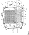
- Figure 1 shows a sectional view of a device 1 according to the invention for recovering heat from an exhaust gas.
- the exhaust gas flows through the exhaust system 2 when a waste heat source generating the exhaust gas is in operation
- Figure 1 The further development shown on the exhaust gas aftertreatment device 3 and the heat exchanger arrangement 4.
- the heat exchanger arrangement 4 is arranged downstream and within the exhaust gas aftertreatment device 3 and has a main flow channel 6 surrounded by the secondary flow channel 5 and the heat exchanger element 7 arranged within the secondary flow channel 5. During operation of the waste heat source, this serves to transfer heat into a working fluid flowing through the heat exchanger element 7.
- the channel closure element 9 is arranged, which serves to regulate the volume flow through the main flow channel 6 and the secondary flow channel 5.
- the volume flow of the exhaust gas through the main flow channel 6 and the secondary flow channel 5 can be regulated as a function of the opening rate of the channel closure element 9 arranged downstream of the heat exchanger arrangement 4.
- the secondary flow channel 5 is connected to the main flow channel 6 in a fluid-permeable manner exclusively via the inlet 17 of the secondary flow channel 5.
- the channel closure element 9 is in this Further development, partially open, so that the exhaust gas flows both through the main flow channel 6 and into the secondary flow channel 5 via the inlet 17. After passing through the secondary flow channel 5 and the main flow channel 6, the exhaust gas flows on the one hand through the exhaust system 2 downstream of the channel closure element 9. The flow of the exhaust gas can be seen from the arrows 28.
- FIG. 2 represents a further development of the device 1 which is not according to the invention.
- the component 11 itself is designed as an SCR catalytic converter.
- the heat exchanger arrangement 4 in turn shows the main flow channel 6 surrounded by the secondary flow channel 5 as well as the heat exchanger element 7 arranged within the secondary flow channel 5, this being designed as the coiled tubing 10.
- the main flow channel 6 is formed by the fluid pipe 16 enclosed by the housing 15 and the damper pipe 20 arranged within the fluid pipe 16.
- the inlet 12 of the main flow channel 6 is formed in the fluid tube 16 and the outlet 8 of the main flow channel 6 is formed in the damper tube 20.
- the secondary flow channel 5 is essentially formed by the fluid space 19, which is formed between the fluid tube 16 and the housing 15 enclosing the fluid tube 16.
- the heat exchanger arrangement 4 shows the silencer structure 14, which is part of the main flow channel 6 of the heat exchanger arrangement 4.
- the muffler structure 14 consists of the fluid pipe 16, the damper pipe 20 and the damper material 24, the damper material 24 being arranged between the fluid pipe 16 and the damper pipe 20.
- the secondary flow channel 5 and here the outlet 18 of the secondary flow channel 5 are connected to the environment 27 in a fluid-permeable manner, so that an exhaust gas flowing via the secondary flow channel is expelled into the environment 27 surrounding the exhaust gas aftertreatment device 3.
- the exhaust gas After passing through the main flow channel 6, on the other hand, the exhaust gas would, following the passage of the channel closure element 9, be introduced within the exhaust system 2 adjoining the channel closure element 9.
- FIG 3 is a representation of the heat exchanger arrangement 4 shown in detail.
- the damper tube 20 has at least two sections 21, 22 has, wherein the first section 21 has a smaller outer diameter and inner diameter than the fluid tube 16.
- the second section 22 of the damper tube 20 is also designed as a funnel-shaped transition area 23, the outer diameter of the transition area 23 corresponding to the inner diameter of the fluid tube 16.
- the second, funnel-shaped section 22 of the damper tube 20 has a circumferential collar 29 formed on the end of the second section 22 facing the inlet 12 of the main flow channel 6 to support the inner wall of the fluid pipe 16 and to enlarge the contact surface between the second section 22 of the damper pipe 20 and the fluid pipe 21 and thereby to increase the tightness against the inflowing exhaust gas.
- the damper tube 20 also has damper openings 30 which break through the wall of the damper tube 20 in the radial direction and which connect the main flow channel 6 to the damper volume 25 in a fluid-permeable manner.
- the damper volume 25 is enclosed by the first and second sections 21, 22 of the damper tube 20 and the fluid tube 16, which is closed on one side.
- the secondary flow channel 5 and here the outlet 18 of the secondary flow channel 5 is in contrast to the in Figure 1 as Figure 2 Further developments shown are connected in a fluid-permeable manner to the exhaust system 2 via the closure bypass channel 26 downstream of the channel closure element 9.
Landscapes
- Engineering & Computer Science (AREA)
- Chemical & Material Sciences (AREA)
- Mechanical Engineering (AREA)
- General Engineering & Computer Science (AREA)
- Combustion & Propulsion (AREA)
- Physics & Mathematics (AREA)
- Thermal Sciences (AREA)
- Chemical Kinetics & Catalysis (AREA)
- Health & Medical Sciences (AREA)
- Toxicology (AREA)
- Geometry (AREA)
- Exhaust Gas After Treatment (AREA)
- Exhaust Silencers (AREA)
Claims (10)
- Dispositif (1) de récupération de la chaleur d'un gaz d'échappement qui traverse un système de gaz d'échappement (2) pendant le fonctionnement d'une source de chaleur perdue produisant le gaz d'échappement, le système de gaz d'échappement (2) comportant au moins un dispositif de post-traitement des gaz d'échappement (3) ainsi qu'au moins un ensemble échangeur thermique (4), l'ensemble échangeur thermique (4) étant ici disposé en aval d'un composant du dispositif de post-traitement des gaz d'échappement (3) et à l'intérieur du dispositif de post-traitement des gaz d'échappement (3) et l'ensemble échangeur thermique (4) comportant un canal d'écoulement principal (6) entouré par un canal d'écoulement secondaire (5) étant traversé en fonctionnement de la source de chaleur perdue par le gaz d'échappement ainsi que par un fluide de travail pour le transfert de chaleur dans le fluide de travail, caractérisé en ce que l'ensemble échangeur thermique (4) comporte en outre un élément échangeur de chaleur (7) disposé à l'intérieur du canal d'écoulement secondaire (5), dans lequel un élément de fermeture de canal (9) est disposé en aval d'une sortie (8) du canal d'écoulement principal (6) et ainsi en dehors du dispositif de post-traitement des gaz d'échappement (3), lequel sert à réguler le débit volumétrique à travers le canal d'écoulement principal (6) et/ou le canal d'écoulement secondaire (5).
- Dispositif (1) selon la revendication 1, caractérisé en ce que l'élément échangeur de chaleur (7) est conçu comme un serpentin hélicoïdal (10) pouvant être traversé par le fluide de travail à partir d'un tube s'étendant essentiellement en forme de spirale.
- Dispositif (1) selon les revendications 1 ou 2, caractérisé en ce que le dispositif de post-traitement des gaz d'échappement (3) ou un composant (11) du dispositif de post-traitement des gaz d'échappement (3) est conçu comme un catalyseur SCR.
- Dispositif (1) selon au moins l'une des revendications précédentes, caractérisé en ce que l'ensemble échangeur thermique (4) et/ou une entrée (12) du canal d'écoulement principal (6) de l'ensemble échangeur thermique (4) est relié(e) par une liaison active à conduction de fluide, par le biais d'un élément de transition (13) disposé en amont de l'ensemble échangeur thermique (4), compensant des contours de section transversale différents, avec le dispositif de post-traitement des gaz d'échappement (3) ou le composant (11) du dispositif de post-traitement des gaz d'échappement (3).
- Dispositif (1) selon au moins l'une des revendications précédentes, caractérisé en ce que l'ensemble échangeur thermique (4) ou le canal d'écoulement principal (6) de l'ensemble échangeur thermique (4) comporte une structure de silencieux (14) et/ou une structure de silencieux (14) forme une partie du canal d'écoulement principal (6) de l'ensemble échangeur thermique (4).
- Dispositif (1) selon au moins l'une des revendications précédentes, caractérisé en ce que le canal d'écoulement principal (6) est formé par un tube de fluide (16) entouré par un boîtier (15) et/ou le tube d'écoulement secondaire (5) comportant une entrée (17) et une sortie (18) est formé par un espace de fluide (19), qui est conçu entre le tube de fluide (16) et le boîtier (15) entourant le tube de fluide (16).
- Dispositif (1) selon au moins l'une des revendications précédentes, caractérisé en ce que le canal d'écoulement principal (6) est formé par le tube de fluide (16) et un tube d'amortisseur (20) disposé à l'intérieur du tube de fluide (16), dans lequel l'entrée (12) du canal d'écoulement principal (6) est conçue dans le tube de fluide (16) et la sortie (8) du canal d'écoulement principal (6) est conçue dans le tube d'amortisseur (20).
- Dispositif (1) selon au moins l'une des revendications précédentes, caractérisé en ce que le tube d'amortisseur (20) comporte au moins deux sections (21, 22), dans lequel une première section (21) présente un diamètre externe et/ou diamètre interne inférieur au tube de fluide (16) et/ou une seconde section (22) du tube d'amortisseur (20) est conçue comme une zone de transition (23) en forme d'entonnoir, dans lequel un diamètre externe de la zone de transition (23) correspond à un diamètre interne du tube de fluide (16).
- Dispositif (1) selon au moins l'une des revendications précédentes, caractérisé en ce que la structure de silencieux (14) est formée par le tube de fluide (16), le tube d'amortisseur (20) et un matériau d'amortisseur (24), dans lequel le matériau d'amortisseur (24) est disposé dans un volume d'amortisseur (25) marqué entre le tube de fluide (16) et le tube d'amortisseur (20).
- Dispositif (1) selon au moins l'une des revendications précédentes, caractérisé en ce que le canal d'écoulement secondaire (5) et/ou la sortie (18) du canal d'écoulement secondaire (5) est relié(e) de manière perméable au fluide par le biais d'un canal de dérivation de fermeture (26) en aval de l'élément de fermeture de canal (9) avec le système de gaz d'échappement (2) ou le canal d'écoulement secondaire (5) et/ou la sortie (18) du canal d'écoulement secondaire (5) avec l'environnement (27).
Applications Claiming Priority (2)
| Application Number | Priority Date | Filing Date | Title |
|---|---|---|---|
| DE102017209726.4A DE102017209726A1 (de) | 2017-06-08 | 2017-06-08 | Vorrichtung zur Wärmerückgewinnung aus einem Abgas |
| PCT/EP2018/063430 WO2018224302A1 (fr) | 2017-06-08 | 2018-05-23 | Dispositif de récupération de la chaleur d'un gaz d'echappement |
Publications (2)
| Publication Number | Publication Date |
|---|---|
| EP3635226A1 EP3635226A1 (fr) | 2020-04-15 |
| EP3635226B1 true EP3635226B1 (fr) | 2021-08-04 |
Family
ID=62222693
Family Applications (1)
| Application Number | Title | Priority Date | Filing Date |
|---|---|---|---|
| EP18726467.6A Active EP3635226B1 (fr) | 2017-06-08 | 2018-05-23 | Dispositif de récupération de la chaleur d'un gaz d'échappement |
Country Status (4)
| Country | Link |
|---|---|
| EP (1) | EP3635226B1 (fr) |
| DE (1) | DE102017209726A1 (fr) |
| RU (1) | RU2735048C1 (fr) |
| WO (1) | WO2018224302A1 (fr) |
Families Citing this family (1)
| Publication number | Priority date | Publication date | Assignee | Title |
|---|---|---|---|---|
| CN112576340A (zh) * | 2019-09-30 | 2021-03-30 | 中联重科股份有限公司 | 尾气排放系统和工程车辆 |
Family Cites Families (15)
| Publication number | Priority date | Publication date | Assignee | Title |
|---|---|---|---|---|
| DE19817340A1 (de) * | 1997-05-02 | 1998-11-05 | Volkswagen Ag | Verfahren zur Erwärmung der Kühlflüssigkeit bei einem Kraftfahrzeug und Abgasanlage |
| CA2247759C (fr) * | 1998-09-18 | 2008-04-15 | Easton Bennett | Echangeur de chaleur pour le systeme d'echappement d'un vehicule automobile |
| JP4566055B2 (ja) * | 2004-09-10 | 2010-10-20 | フタバ産業株式会社 | 排気熱回収マフラ |
| WO2006090725A1 (fr) * | 2005-02-23 | 2006-08-31 | Sango Co., Ltd. | Dispositif de recuperation de chaleur de rejet |
| GB2436855A (en) * | 2006-04-05 | 2007-10-10 | David Davies | Combustion apparatus, eg diesel engine, with exhaust gas recirculation |
| JP2008133782A (ja) * | 2006-11-29 | 2008-06-12 | Calsonic Kansei Corp | 排気熱回収装置 |
| KR101125004B1 (ko) * | 2009-12-04 | 2012-03-27 | 기아자동차주식회사 | 냉각수 및 오일 통합 열교환형 배기열 회수장치 |
| DE102010011472A1 (de) * | 2010-03-15 | 2011-09-15 | Bayerische Motoren Werke Aktiengesellschaft | Vorrichtung zur Abgaswärmenutzung |
| US8752378B2 (en) * | 2010-08-09 | 2014-06-17 | Cummins Intellectual Properties, Inc. | Waste heat recovery system for recapturing energy after engine aftertreatment systems |
| DE102011016886A1 (de) | 2011-04-13 | 2012-10-18 | Emitec Gesellschaft Für Emissionstechnologie Mbh | Vorrichtung mit einem Wärmetauscher für einen thermoelektrischen Generator eines Kraftfahrzeugs |
| JP5769675B2 (ja) * | 2012-08-10 | 2015-08-26 | フタバ産業株式会社 | 排気熱回収装置 |
| KR101421958B1 (ko) | 2013-08-06 | 2014-07-22 | 현대자동차주식회사 | 차량의 배기열 활용 구조 |
| KR101499221B1 (ko) * | 2013-11-14 | 2015-03-05 | 현대자동차주식회사 | 밸브 액추에이터 내장형 배기열 회수장치 |
| RU147861U1 (ru) * | 2014-02-17 | 2014-11-20 | Игорь Юрьевич Исаев | Вторичный паросиловой контур двс транспортного средства |
| EP3161288B1 (fr) | 2014-06-26 | 2018-09-26 | Volvo Truck Corporation | Agencement de gaz d'échappement |
-
2017
- 2017-06-08 DE DE102017209726.4A patent/DE102017209726A1/de not_active Withdrawn
-
2018
- 2018-05-23 WO PCT/EP2018/063430 patent/WO2018224302A1/fr not_active Ceased
- 2018-05-23 EP EP18726467.6A patent/EP3635226B1/fr active Active
- 2018-05-23 RU RU2019143436A patent/RU2735048C1/ru active
Non-Patent Citations (1)
| Title |
|---|
| None * |
Also Published As
| Publication number | Publication date |
|---|---|
| WO2018224302A1 (fr) | 2018-12-13 |
| RU2735048C1 (ru) | 2020-10-27 |
| EP3635226A1 (fr) | 2020-04-15 |
| DE102017209726A1 (de) | 2018-12-27 |
Similar Documents
| Publication | Publication Date | Title |
|---|---|---|
| DE102011103110B4 (de) | Abgassystem mit Kreislaufwärmerohr | |
| EP2708712B1 (fr) | Échangeur de chaleur de gaz d'échappement | |
| EP2324217B1 (fr) | Association échangeur de chaleur et catalyseur en tant que composant d'un système d'échappement | |
| DE102018222512B4 (de) | Verfahren zum Betreiben einer Antriebseinrichtung sowie entsprechende Antriebseinrichtung | |
| EP2715086B1 (fr) | Échangeur de chaleur | |
| DE102010010624A1 (de) | Koaxialer Wärmetauscher für eine Kraftfahrzeug-Abgasanlage | |
| EP3500737B1 (fr) | Composante d'un système des gaz d'échappement et procédé de post-traitement des gaz d'échappement | |
| DE202010003049U1 (de) | Vorrichtung zur Abgaswärmenutzung | |
| EP3406869B1 (fr) | Installation d'échappement de gaz pour un véhicule automobile ainsi que automobile correspondant | |
| EP3635320B1 (fr) | Dispositif de récupération de chaleur d'un fluide chauffant | |
| DE102013111033B4 (de) | Verfahren und Vorrichtung für Thermomanagement einer Kfz-Abgasanlage | |
| DE10228619B4 (de) | Abgasrohr für die Abgasanlage eines Kraftfahrzeugs | |
| WO2018224302A1 (fr) | Dispositif de récupération de la chaleur d'un gaz d'echappement | |
| WO2018158286A1 (fr) | Dispositif de chauffage | |
| EP3635314B1 (fr) | Dispositif de récupération de chaleur | |
| EP3306045B1 (fr) | Épurateur de gaz d'échappement, dispositif d'entraînement ainsi que procédé de fonctionnement d'un dispositif d'entraînement | |
| DE102009055686A1 (de) | Wärmeübertrager für eine mobile Heizeinrichtung, mobile Heizeinrichtung und Kraftfahrzeug | |
| EP1496327B1 (fr) | Echangeur de chaleur | |
| DE102012210338A1 (de) | Aufheizvorrichtung für Abgasreinigungsanlage | |
| EP2853706B1 (fr) | Élément de refroidissement et installation de gaz d'échappement, comprenant un élément de refroidissement | |
| DE102014215521A1 (de) | Abgasrückführungsanordnung | |
| EP1690057B1 (fr) | Echangeur thermique, en particulier echangeur thermique de gaz d'echappement | |
| EP3722694A1 (fr) | Module d'échangeur de chaleur | |
| DE102010054508A1 (de) | Abgasrückführvorrichtung für eine Verbrennungskraftmaschine | |
| DE102019203847A1 (de) | Antriebseinrichtung für ein Kraftfahrzeug mit einer Abgasleitung, einem Vorratsbehälter für ein Betriebsmittel und einem Wärmerohr sowie Verfahren zum Betreiben einer Antriebseinrichtung |
Legal Events
| Date | Code | Title | Description |
|---|---|---|---|
| STAA | Information on the status of an ep patent application or granted ep patent |
Free format text: STATUS: UNKNOWN |
|
| STAA | Information on the status of an ep patent application or granted ep patent |
Free format text: STATUS: THE INTERNATIONAL PUBLICATION HAS BEEN MADE |
|
| PUAI | Public reference made under article 153(3) epc to a published international application that has entered the european phase |
Free format text: ORIGINAL CODE: 0009012 |
|
| STAA | Information on the status of an ep patent application or granted ep patent |
Free format text: STATUS: REQUEST FOR EXAMINATION WAS MADE |
|
| 17P | Request for examination filed |
Effective date: 20200108 |
|
| AK | Designated contracting states |
Kind code of ref document: A1 Designated state(s): AL AT BE BG CH CY CZ DE DK EE ES FI FR GB GR HR HU IE IS IT LI LT LU LV MC MK MT NL NO PL PT RO RS SE SI SK SM TR |
|
| AX | Request for extension of the european patent |
Extension state: BA ME |
|
| STAA | Information on the status of an ep patent application or granted ep patent |
Free format text: STATUS: EXAMINATION IS IN PROGRESS |
|
| DAV | Request for validation of the european patent (deleted) | ||
| DAX | Request for extension of the european patent (deleted) | ||
| 17Q | First examination report despatched |
Effective date: 20200910 |
|
| GRAP | Despatch of communication of intention to grant a patent |
Free format text: ORIGINAL CODE: EPIDOSNIGR1 |
|
| STAA | Information on the status of an ep patent application or granted ep patent |
Free format text: STATUS: GRANT OF PATENT IS INTENDED |
|
| INTG | Intention to grant announced |
Effective date: 20210517 |
|
| GRAS | Grant fee paid |
Free format text: ORIGINAL CODE: EPIDOSNIGR3 |
|
| GRAA | (expected) grant |
Free format text: ORIGINAL CODE: 0009210 |
|
| STAA | Information on the status of an ep patent application or granted ep patent |
Free format text: STATUS: THE PATENT HAS BEEN GRANTED |
|
| AK | Designated contracting states |
Kind code of ref document: B1 Designated state(s): AL AT BE BG CH CY CZ DE DK EE ES FI FR GB GR HR HU IE IS IT LI LT LU LV MC MK MT NL NO PL PT RO RS SE SI SK SM TR |
|
| REG | Reference to a national code |
Ref country code: GB Ref legal event code: FG4D Free format text: NOT ENGLISH |
|
| REG | Reference to a national code |
Ref country code: AT Ref legal event code: REF Ref document number: 1417198 Country of ref document: AT Kind code of ref document: T Effective date: 20210815 |
|
| REG | Reference to a national code |
Ref country code: CH Ref legal event code: EP |
|
| REG | Reference to a national code |
Ref country code: DE Ref legal event code: R096 Ref document number: 502018006430 Country of ref document: DE |
|
| REG | Reference to a national code |
Ref country code: IE Ref legal event code: FG4D Free format text: LANGUAGE OF EP DOCUMENT: GERMAN |
|
| REG | Reference to a national code |
Ref country code: LT Ref legal event code: MG9D |
|
| REG | Reference to a national code |
Ref country code: NL Ref legal event code: MP Effective date: 20210804 |
|
| PG25 | Lapsed in a contracting state [announced via postgrant information from national office to epo] |
Ref country code: BG Free format text: LAPSE BECAUSE OF FAILURE TO SUBMIT A TRANSLATION OF THE DESCRIPTION OR TO PAY THE FEE WITHIN THE PRESCRIBED TIME-LIMIT Effective date: 20211104 Ref country code: LT Free format text: LAPSE BECAUSE OF FAILURE TO SUBMIT A TRANSLATION OF THE DESCRIPTION OR TO PAY THE FEE WITHIN THE PRESCRIBED TIME-LIMIT Effective date: 20210804 Ref country code: PT Free format text: LAPSE BECAUSE OF FAILURE TO SUBMIT A TRANSLATION OF THE DESCRIPTION OR TO PAY THE FEE WITHIN THE PRESCRIBED TIME-LIMIT Effective date: 20211206 Ref country code: NO Free format text: LAPSE BECAUSE OF FAILURE TO SUBMIT A TRANSLATION OF THE DESCRIPTION OR TO PAY THE FEE WITHIN THE PRESCRIBED TIME-LIMIT Effective date: 20211104 Ref country code: ES Free format text: LAPSE BECAUSE OF FAILURE TO SUBMIT A TRANSLATION OF THE DESCRIPTION OR TO PAY THE FEE WITHIN THE PRESCRIBED TIME-LIMIT Effective date: 20210804 Ref country code: FI Free format text: LAPSE BECAUSE OF FAILURE TO SUBMIT A TRANSLATION OF THE DESCRIPTION OR TO PAY THE FEE WITHIN THE PRESCRIBED TIME-LIMIT Effective date: 20210804 Ref country code: HR Free format text: LAPSE BECAUSE OF FAILURE TO SUBMIT A TRANSLATION OF THE DESCRIPTION OR TO PAY THE FEE WITHIN THE PRESCRIBED TIME-LIMIT Effective date: 20210804 Ref country code: RS Free format text: LAPSE BECAUSE OF FAILURE TO SUBMIT A TRANSLATION OF THE DESCRIPTION OR TO PAY THE FEE WITHIN THE PRESCRIBED TIME-LIMIT Effective date: 20210804 Ref country code: SE Free format text: LAPSE BECAUSE OF FAILURE TO SUBMIT A TRANSLATION OF THE DESCRIPTION OR TO PAY THE FEE WITHIN THE PRESCRIBED TIME-LIMIT Effective date: 20210804 |
|
| PG25 | Lapsed in a contracting state [announced via postgrant information from national office to epo] |
Ref country code: PL Free format text: LAPSE BECAUSE OF FAILURE TO SUBMIT A TRANSLATION OF THE DESCRIPTION OR TO PAY THE FEE WITHIN THE PRESCRIBED TIME-LIMIT Effective date: 20210804 Ref country code: LV Free format text: LAPSE BECAUSE OF FAILURE TO SUBMIT A TRANSLATION OF THE DESCRIPTION OR TO PAY THE FEE WITHIN THE PRESCRIBED TIME-LIMIT Effective date: 20210804 Ref country code: GR Free format text: LAPSE BECAUSE OF FAILURE TO SUBMIT A TRANSLATION OF THE DESCRIPTION OR TO PAY THE FEE WITHIN THE PRESCRIBED TIME-LIMIT Effective date: 20211105 |
|
| PG25 | Lapsed in a contracting state [announced via postgrant information from national office to epo] |
Ref country code: NL Free format text: LAPSE BECAUSE OF FAILURE TO SUBMIT A TRANSLATION OF THE DESCRIPTION OR TO PAY THE FEE WITHIN THE PRESCRIBED TIME-LIMIT Effective date: 20210804 |
|
| PG25 | Lapsed in a contracting state [announced via postgrant information from national office to epo] |
Ref country code: DK Free format text: LAPSE BECAUSE OF FAILURE TO SUBMIT A TRANSLATION OF THE DESCRIPTION OR TO PAY THE FEE WITHIN THE PRESCRIBED TIME-LIMIT Effective date: 20210804 |
|
| REG | Reference to a national code |
Ref country code: DE Ref legal event code: R097 Ref document number: 502018006430 Country of ref document: DE |
|
| PG25 | Lapsed in a contracting state [announced via postgrant information from national office to epo] |
Ref country code: SM Free format text: LAPSE BECAUSE OF FAILURE TO SUBMIT A TRANSLATION OF THE DESCRIPTION OR TO PAY THE FEE WITHIN THE PRESCRIBED TIME-LIMIT Effective date: 20210804 Ref country code: SK Free format text: LAPSE BECAUSE OF FAILURE TO SUBMIT A TRANSLATION OF THE DESCRIPTION OR TO PAY THE FEE WITHIN THE PRESCRIBED TIME-LIMIT Effective date: 20210804 Ref country code: RO Free format text: LAPSE BECAUSE OF FAILURE TO SUBMIT A TRANSLATION OF THE DESCRIPTION OR TO PAY THE FEE WITHIN THE PRESCRIBED TIME-LIMIT Effective date: 20210804 Ref country code: EE Free format text: LAPSE BECAUSE OF FAILURE TO SUBMIT A TRANSLATION OF THE DESCRIPTION OR TO PAY THE FEE WITHIN THE PRESCRIBED TIME-LIMIT Effective date: 20210804 Ref country code: CZ Free format text: LAPSE BECAUSE OF FAILURE TO SUBMIT A TRANSLATION OF THE DESCRIPTION OR TO PAY THE FEE WITHIN THE PRESCRIBED TIME-LIMIT Effective date: 20210804 Ref country code: AL Free format text: LAPSE BECAUSE OF FAILURE TO SUBMIT A TRANSLATION OF THE DESCRIPTION OR TO PAY THE FEE WITHIN THE PRESCRIBED TIME-LIMIT Effective date: 20210804 |
|
| PLBE | No opposition filed within time limit |
Free format text: ORIGINAL CODE: 0009261 |
|
| STAA | Information on the status of an ep patent application or granted ep patent |
Free format text: STATUS: NO OPPOSITION FILED WITHIN TIME LIMIT |
|
| 26N | No opposition filed |
Effective date: 20220506 |
|
| PG25 | Lapsed in a contracting state [announced via postgrant information from national office to epo] |
Ref country code: IT Free format text: LAPSE BECAUSE OF FAILURE TO SUBMIT A TRANSLATION OF THE DESCRIPTION OR TO PAY THE FEE WITHIN THE PRESCRIBED TIME-LIMIT Effective date: 20210804 |
|
| PG25 | Lapsed in a contracting state [announced via postgrant information from national office to epo] |
Ref country code: SI Free format text: LAPSE BECAUSE OF FAILURE TO SUBMIT A TRANSLATION OF THE DESCRIPTION OR TO PAY THE FEE WITHIN THE PRESCRIBED TIME-LIMIT Effective date: 20210804 |
|
| REG | Reference to a national code |
Ref country code: CH Ref legal event code: PL |
|
| REG | Reference to a national code |
Ref country code: BE Ref legal event code: MM Effective date: 20220531 |
|
| PG25 | Lapsed in a contracting state [announced via postgrant information from national office to epo] |
Ref country code: MC Free format text: LAPSE BECAUSE OF FAILURE TO SUBMIT A TRANSLATION OF THE DESCRIPTION OR TO PAY THE FEE WITHIN THE PRESCRIBED TIME-LIMIT Effective date: 20210804 Ref country code: LU Free format text: LAPSE BECAUSE OF NON-PAYMENT OF DUE FEES Effective date: 20220523 Ref country code: LI Free format text: LAPSE BECAUSE OF NON-PAYMENT OF DUE FEES Effective date: 20220531 Ref country code: CH Free format text: LAPSE BECAUSE OF NON-PAYMENT OF DUE FEES Effective date: 20220531 |
|
| PG25 | Lapsed in a contracting state [announced via postgrant information from national office to epo] |
Ref country code: IE Free format text: LAPSE BECAUSE OF NON-PAYMENT OF DUE FEES Effective date: 20220523 |
|
| PG25 | Lapsed in a contracting state [announced via postgrant information from national office to epo] |
Ref country code: BE Free format text: LAPSE BECAUSE OF NON-PAYMENT OF DUE FEES Effective date: 20220531 |
|
| P01 | Opt-out of the competence of the unified patent court (upc) registered |
Effective date: 20230523 |
|
| PG25 | Lapsed in a contracting state [announced via postgrant information from national office to epo] |
Ref country code: MK Free format text: LAPSE BECAUSE OF FAILURE TO SUBMIT A TRANSLATION OF THE DESCRIPTION OR TO PAY THE FEE WITHIN THE PRESCRIBED TIME-LIMIT Effective date: 20210804 Ref country code: CY Free format text: LAPSE BECAUSE OF FAILURE TO SUBMIT A TRANSLATION OF THE DESCRIPTION OR TO PAY THE FEE WITHIN THE PRESCRIBED TIME-LIMIT Effective date: 20210804 |
|
| PG25 | Lapsed in a contracting state [announced via postgrant information from national office to epo] |
Ref country code: HU Free format text: LAPSE BECAUSE OF FAILURE TO SUBMIT A TRANSLATION OF THE DESCRIPTION OR TO PAY THE FEE WITHIN THE PRESCRIBED TIME-LIMIT; INVALID AB INITIO Effective date: 20180523 |
|
| PGFP | Annual fee paid to national office [announced via postgrant information from national office to epo] |
Ref country code: GB Payment date: 20240521 Year of fee payment: 7 |
|
| PGFP | Annual fee paid to national office [announced via postgrant information from national office to epo] |
Ref country code: DE Payment date: 20240531 Year of fee payment: 7 |
|
| REG | Reference to a national code |
Ref country code: AT Ref legal event code: MM01 Ref document number: 1417198 Country of ref document: AT Kind code of ref document: T Effective date: 20230523 |
|
| PG25 | Lapsed in a contracting state [announced via postgrant information from national office to epo] |
Ref country code: AT Free format text: LAPSE BECAUSE OF NON-PAYMENT OF DUE FEES Effective date: 20230523 |
|
| PG25 | Lapsed in a contracting state [announced via postgrant information from national office to epo] |
Ref country code: AT Free format text: LAPSE BECAUSE OF NON-PAYMENT OF DUE FEES Effective date: 20230523 |
|
| PGFP | Annual fee paid to national office [announced via postgrant information from national office to epo] |
Ref country code: FR Payment date: 20240527 Year of fee payment: 7 |
|
| PG25 | Lapsed in a contracting state [announced via postgrant information from national office to epo] |
Ref country code: MT Free format text: LAPSE BECAUSE OF FAILURE TO SUBMIT A TRANSLATION OF THE DESCRIPTION OR TO PAY THE FEE WITHIN THE PRESCRIBED TIME-LIMIT Effective date: 20210804 |
|
| REG | Reference to a national code |
Ref country code: DE Ref legal event code: R119 Ref document number: 502018006430 Country of ref document: DE |
|
| PG25 | Lapsed in a contracting state [announced via postgrant information from national office to epo] |
Ref country code: TR Free format text: LAPSE BECAUSE OF FAILURE TO SUBMIT A TRANSLATION OF THE DESCRIPTION OR TO PAY THE FEE WITHIN THE PRESCRIBED TIME-LIMIT Effective date: 20210804 |
|
| GBPC | Gb: european patent ceased through non-payment of renewal fee |
Effective date: 20250523 |
|
| PG25 | Lapsed in a contracting state [announced via postgrant information from national office to epo] |
Ref country code: GB Free format text: LAPSE BECAUSE OF NON-PAYMENT OF DUE FEES Effective date: 20250523 |
|
| PG25 | Lapsed in a contracting state [announced via postgrant information from national office to epo] |
Ref country code: DE Free format text: LAPSE BECAUSE OF NON-PAYMENT OF DUE FEES Effective date: 20251202 |
|
| PGFP | Annual fee paid to national office [announced via postgrant information from national office to epo] |
Ref country code: AT Payment date: 20260410 Year of fee payment: 5 |
|
| PG25 | Lapsed in a contracting state [announced via postgrant information from national office to epo] |
Ref country code: FR Free format text: LAPSE BECAUSE OF NON-PAYMENT OF DUE FEES Effective date: 20250531 |