EP3635249B1 - Montage de tour pour une turbine a vent et méthode de réglage d'une telle tour - Google Patents
Montage de tour pour une turbine a vent et méthode de réglage d'une telle tour Download PDFInfo
- Publication number
- EP3635249B1 EP3635249B1 EP18799377.9A EP18799377A EP3635249B1 EP 3635249 B1 EP3635249 B1 EP 3635249B1 EP 18799377 A EP18799377 A EP 18799377A EP 3635249 B1 EP3635249 B1 EP 3635249B1
- Authority
- EP
- European Patent Office
- Prior art keywords
- tower
- section
- length
- defining
- tower section
- Prior art date
- Legal status (The legal status is an assumption and is not a legal conclusion. Google has not performed a legal analysis and makes no representation as to the accuracy of the status listed.)
- Active
Links
Images



Classifications
-
- E—FIXED CONSTRUCTIONS
- E04—BUILDING
- E04H—BUILDINGS OR LIKE STRUCTURES FOR PARTICULAR PURPOSES; SWIMMING OR SPLASH BATHS OR POOLS; MASTS; FENCING; TENTS OR CANOPIES, IN GENERAL
- E04H12/00—Towers; Masts or poles; Chimney stacks; Water-towers; Methods of erecting such structures
- E04H12/34—Arrangements for erecting or lowering towers, masts, poles, chimney stacks, or the like
- E04H12/342—Arrangements for stacking tower sections on top of each other
-
- F—MECHANICAL ENGINEERING; LIGHTING; HEATING; WEAPONS; BLASTING
- F03—MACHINES OR ENGINES FOR LIQUIDS; WIND, SPRING, OR WEIGHT MOTORS; PRODUCING MECHANICAL POWER OR A REACTIVE PROPULSIVE THRUST, NOT OTHERWISE PROVIDED FOR
- F03D—WIND MOTORS
- F03D13/00—Assembly, mounting or commissioning of wind motors; Arrangements specially adapted for transporting wind motor components
- F03D13/20—Arrangements for mounting or supporting wind motors; Masts or towers for wind motors
-
- F—MECHANICAL ENGINEERING; LIGHTING; HEATING; WEAPONS; BLASTING
- F05—INDEXING SCHEMES RELATING TO ENGINES OR PUMPS IN VARIOUS SUBCLASSES OF CLASSES F01-F04
- F05B—INDEXING SCHEME RELATING TO WIND, SPRING, WEIGHT, INERTIA OR LIKE MOTORS, TO MACHINES OR ENGINES FOR LIQUIDS COVERED BY SUBCLASSES F03B, F03D AND F03G
- F05B2230/00—Manufacture
- F05B2230/60—Assembly methods
-
- F—MECHANICAL ENGINEERING; LIGHTING; HEATING; WEAPONS; BLASTING
- F05—INDEXING SCHEMES RELATING TO ENGINES OR PUMPS IN VARIOUS SUBCLASSES OF CLASSES F01-F04
- F05B—INDEXING SCHEME RELATING TO WIND, SPRING, WEIGHT, INERTIA OR LIKE MOTORS, TO MACHINES OR ENGINES FOR LIQUIDS COVERED BY SUBCLASSES F03B, F03D AND F03G
- F05B2240/00—Components
- F05B2240/90—Mounting on supporting structures or systems
- F05B2240/91—Mounting on supporting structures or systems on a stationary structure
- F05B2240/912—Mounting on supporting structures or systems on a stationary structure on a tower
-
- F—MECHANICAL ENGINEERING; LIGHTING; HEATING; WEAPONS; BLASTING
- F05—INDEXING SCHEMES RELATING TO ENGINES OR PUMPS IN VARIOUS SUBCLASSES OF CLASSES F01-F04
- F05B—INDEXING SCHEME RELATING TO WIND, SPRING, WEIGHT, INERTIA OR LIKE MOTORS, TO MACHINES OR ENGINES FOR LIQUIDS COVERED BY SUBCLASSES F03B, F03D AND F03G
- F05B2240/00—Components
- F05B2240/90—Mounting on supporting structures or systems
- F05B2240/91—Mounting on supporting structures or systems on a stationary structure
- F05B2240/915—Mounting on supporting structures or systems on a stationary structure which is vertically adjustable
-
- Y—GENERAL TAGGING OF NEW TECHNOLOGICAL DEVELOPMENTS; GENERAL TAGGING OF CROSS-SECTIONAL TECHNOLOGIES SPANNING OVER SEVERAL SECTIONS OF THE IPC; TECHNICAL SUBJECTS COVERED BY FORMER USPC CROSS-REFERENCE ART COLLECTIONS [XRACs] AND DIGESTS
- Y02—TECHNOLOGIES OR APPLICATIONS FOR MITIGATION OR ADAPTATION AGAINST CLIMATE CHANGE
- Y02E—REDUCTION OF GREENHOUSE GAS [GHG] EMISSIONS, RELATED TO ENERGY GENERATION, TRANSMISSION OR DISTRIBUTION
- Y02E10/00—Energy generation through renewable energy sources
- Y02E10/70—Wind energy
- Y02E10/72—Wind turbines with rotation axis in wind direction
-
- Y—GENERAL TAGGING OF NEW TECHNOLOGICAL DEVELOPMENTS; GENERAL TAGGING OF CROSS-SECTIONAL TECHNOLOGIES SPANNING OVER SEVERAL SECTIONS OF THE IPC; TECHNICAL SUBJECTS COVERED BY FORMER USPC CROSS-REFERENCE ART COLLECTIONS [XRACs] AND DIGESTS
- Y02—TECHNOLOGIES OR APPLICATIONS FOR MITIGATION OR ADAPTATION AGAINST CLIMATE CHANGE
- Y02E—REDUCTION OF GREENHOUSE GAS [GHG] EMISSIONS, RELATED TO ENERGY GENERATION, TRANSMISSION OR DISTRIBUTION
- Y02E10/00—Energy generation through renewable energy sources
- Y02E10/70—Wind energy
- Y02E10/727—Offshore wind turbines
-
- Y—GENERAL TAGGING OF NEW TECHNOLOGICAL DEVELOPMENTS; GENERAL TAGGING OF CROSS-SECTIONAL TECHNOLOGIES SPANNING OVER SEVERAL SECTIONS OF THE IPC; TECHNICAL SUBJECTS COVERED BY FORMER USPC CROSS-REFERENCE ART COLLECTIONS [XRACs] AND DIGESTS
- Y02—TECHNOLOGIES OR APPLICATIONS FOR MITIGATION OR ADAPTATION AGAINST CLIMATE CHANGE
- Y02E—REDUCTION OF GREENHOUSE GAS [GHG] EMISSIONS, RELATED TO ENERGY GENERATION, TRANSMISSION OR DISTRIBUTION
- Y02E10/00—Energy generation through renewable energy sources
- Y02E10/70—Wind energy
- Y02E10/728—Onshore wind turbines
-
- Y—GENERAL TAGGING OF NEW TECHNOLOGICAL DEVELOPMENTS; GENERAL TAGGING OF CROSS-SECTIONAL TECHNOLOGIES SPANNING OVER SEVERAL SECTIONS OF THE IPC; TECHNICAL SUBJECTS COVERED BY FORMER USPC CROSS-REFERENCE ART COLLECTIONS [XRACs] AND DIGESTS
- Y02—TECHNOLOGIES OR APPLICATIONS FOR MITIGATION OR ADAPTATION AGAINST CLIMATE CHANGE
- Y02P—CLIMATE CHANGE MITIGATION TECHNOLOGIES IN THE PRODUCTION OR PROCESSING OF GOODS
- Y02P70/00—Climate change mitigation technologies in the production process for final industrial or consumer products
- Y02P70/50—Manufacturing or production processes characterised by the final manufactured product
Definitions
- the present invention relates generally to a tower assembly according to claim 1 and a method according to claim 7 for adjusting a tower of a wind turbine, and more particularly, to tower assemblies for wind turbines having adjustable hub heights.
- Wind power is considered one of the cleanest, most environmentally friendly energy sources presently available, and wind turbines have gained increased attention in this regard.
- a modern wind turbine typically includes a tower, a generator, a gearbox, a nacelle, and one or more rotor blades.
- the rotor blades capture kinetic energy from wind using known airfoil principles and transmit the kinetic energy through rotational energy to turn a main shaft coupling the rotor blades to a gearbox, or if a gearbox is not used, directly to the generator.
- the generator then converts the mechanical energy to electrical energy that may be deployed to a utility grid.
- the wind turbine tower typically includes a base tower section secured to a foundation and one or more upper tower sections secured atop the base tower section to form a tower of a certain height.
- the foundation may be a concrete slab foundation, an anchor cage foundation, or any other suitable foundation capable of supporting loads produced by the wind and/or gravitational forces.
- each tower section generally includes a cylindrical wall defining an outer diameter and an inner diameter separated by a radial thickness that is uniform along the entire length of the sections.
- WO 2017/039922 A1 relates to a concrete equipment tower with tensioning tendon guide slot.
- the tower may include a foundation, a bottom tower portion, a middle tower portion, a top tower portion and a steel tip adapter.
- the steel tip adapter may be used to support a nacelle of a wind turbine.
- Each tower portion may be formed with a plurality of tower segments, respectively, that may be formed of precast concrete. Transition segments may be positioned between appropriate tower portions to accommodate a progressive change in the diameter of tower segments from the bottom to the top of equipment tower.
- US 2013/0174508 A1 relates to a platform assembly for a wind turbine tower.
- EP 2 060 706 A2 relates to a tower with a platform.
- the overall tower height of wind turbines may be dependent on a number of factors.
- the tower height may vary based on environmental conditions at the wind turbine site and/or costs of materials.
- increasing the tower height allows for longer rotor blades which in turn produce more power.
- conventional tower heights can be increased or decreased by modifying the number of tower sections stacked together.
- additional manufacturing steps are required to ensure that the tower can withstand site and component loading. More specifically, if a certain site requires a tower with an increased height to harvest higher wind speeds, the cylindrical walls of the corresponding wall sections are designed with a thicker radial thickness to account for higher loads.
- the cylindrical walls of the corresponding wall sections are designed with a thinner radial thickness to save material costs.
- a tower is designed with a thicker or thinner radial thickness, it is difficult for an operator to tell the difference when assembling the tower.
- tower heights have to be specifically designed for differing site and loading conditions.
- additional efforts are spent identifying and locating which tower sections should be used for which tower, e.g. at a wind farm.
- the present disclosure is directed to a tower assembly for a wind turbine having an adjustable hub height that does not require a redesign for every site.
- a tower assembly for a wind turbine having an adjustable height includes at least one base tower section having a cylindrical base wall defining an overall length extending from a first end to a second end.
- the cylindrical base wall further defines an outer diameter that is uniform along the entire length from the first end to the second end.
- the tower assembly also includes an adjustable upper tower section arranged atop the base tower section.
- the upper tower section includes a first tower portion integral with a second tower portion.
- the first tower portion includes a first tower wall portion defining a first length extending from a first end to a second end. Further, the first tower wall portion includes a tapering cross-section from the first end to the second end of the first length thereof.
- the second tower portion includes a second tower wall portion defining a second length extending from a first end to a second end. Further, the second tower wall portion defines a uniform cylindrical cross-section from the first end to the second end of the second length thereof.
- the tapering cross-section of the first tower wall portion may taper towards the second tower portion.
- the tower assembly may further include a transitional tower section arranged between the base tower section and the upper tower section.
- the transitional tower section includes an outer wall defining a length extending from a first end to a second end. Further, in certain embodiments, the outer wall of the transitional tower section may define an outer diameter that tapers along the length thereof.
- the second tower portion of the upper tower section may include an upper tower can mountable to a nacelle of the wind turbine.
- the second tower portion of the upper tower section may be constructed of one or more removable tower cans arranged below the upper tower can.
- the tower assembly may further include at least one platform in any one of the base tower section, the transitional tower section, and/or the upper tower section.
- the tower assembly may include at least one platform in the second tower portion of the upper tower section.
- the present disclosure is directed to an adjustable upper tower section for a tower of a wind turbine.
- the upper tower section includes a first tower portion having a first tower wall portion defining a first length extending from a first end to a second end.
- the first tower wall portion includes a tapering cross-section from the first end to the second end of the first length thereof.
- the upper tower section also includes a second tower portion integral with the first tower portion.
- the second tower portion includes a second tower wall portion defining a second length extending from a first end to a second end.
- the second tower wall portion defines a uniform cylindrical cross-section from the first end to the second end of the second length thereof. It should also be understood that the upper tower section may further include any of the additional features as described herein.
- a method for adjusting a tower height of a wind turbine includes securing a base tower section to a foundation.
- the base tower section has a cylindrical base wall defining an outer diameter that is uniform along its entire length.
- the method also includes mounting an adjustable upper tower section atop the base tower section.
- the upper tower section has a first tower portion integral with an adjustable second tower portion.
- the first tower portion has a first tower wall portion defining a first length extending from a first end to a second end. Further, the first tower wall portion has a tapering cross-section from the first end to the second end of the first length thereof.
- the second tower portion has a second tower wall portion defining a second length extending from a first end to a second end. Moreover, the second tower wall portion defines a uniform cylindrical cross-section from the first end to the second end of the second length thereof.
- the method further includes evaluating at least one of site conditions or loading conditions of the wind turbine and adjusting a height of the second tower portion based on the evaluation.
- the step of adjusting the height of the second tower portion based on the evaluation may include adding or removing at least one tower can of the second tower portion. More specifically, in certain embodiments, the step of adding or removing at least one tower can to the second tower portion may include adding or removing at least one tower can below an upper tower can of the second tower portion.
- the method may include mounting a transitional tower section between the base tower section and the upper tower section.
- the transitional tower section may include an outer wall defining a length extending from a first end to a second end. More specifically, as mentioned, the outer wall of the transitional tower section may define an outer diameter that tapers along the length thereof.
- the method may also include installing at least one platform in the second tower portion after adding or removing at least one tower can thereto. It should be understood that the method may further include any of the additional steps, features and/or embodiments as described herein.
- the present disclosure is directed to a tower assembly for a wind turbine having an adjustable height.
- the hub height can be adjusted to 100% tower capacity so as to maximize energy production.
- the tower assembly includes an adjustable upper tower section having a first tower portion integral with a second tower portion.
- the first tower portion includes a first tower wall portion defining a first length extending from a first end to a second end. Further, the first tower wall portion includes a tapering cross-section from the first end to the second end of the first length thereof.
- the second tower portion includes a second tower wall portion defining a second length extending from a first end to a second end. Further, the second tower wall portion defines a uniform cylindrical cross-section from the first end to the second end of the second length thereof.
- the second tower portion is constructed of a plurality of removable tower cans that can be added or removed to adjust an overall height of the tower assembly.
- the adjustable upper tower section has a partially cylindrical cross-section providing many advantages not present in the prior art.
- the tower assembly of the present disclosure is configured to optimize the tower height (and therefore hub height) based on site and/or loading conditions. Further, by providing a tower assembly with a height can that be easily increased, higher energy levels can be achieved at multiple wind turbine sites. Moreover, the tower assembly of the present disclosure provides a flexible assembly that can be easily sourced multiple wind turbine sites. In addition, the tower assembly of the present disclosure allows for positioning of the same platform for multiple configurations or heights of the tower assembly.
- the adjustable upper tower section can extend higher in order to harvest the higher winds and utilize 100% original tower capacity.
- the adjustable upper tower section can be shortened to accommodate the lower winds and not exceed 100% original tower capacity.
- the tower sections described herein that are below the upper tower section are identical and the upper section differs only by the length of the cylindrical segment.
- FIG. 1 illustrates a perspective view of one embodiment of a wind turbine 10 according to the present disclosure.
- the wind turbine 10 generally includes a tower 12, a nacelle 14 mounted on the tower 12, and a rotor 16 coupled to the nacelle 14.
- the tower 12 extends generally perpendicular to a foundation or support surface 17 may be secured to the foundation 17 using any suitable means, such as anchor bolts (not shown).
- the tower 12 also generally referred to herein as a tower assembly 22
- the rotor 16 includes a rotatable hub 18 and at least one rotor blade 20 coupled to and extending outwardly from the hub 18.
- the rotor 16 includes three rotor blades 20.
- the rotor 16 may include more or less than three rotor blades 20.
- Each rotor blade 20 may be spaced about the hub 18 to facilitate rotating the rotor 16 to enable kinetic energy to be transferred from the wind into usable mechanical energy, and subsequently, electrical energy.
- the hub 18 may be rotatably coupled to an electric generator (not shown) positioned within the nacelle 14 to permit electrical energy to be produced.
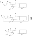
- FIG. 2 various embodiments of a tower assembly 22 for a wind turbine 10 having an adjustable height according to the present disclosure is illustrated. More specifically, as shown, FIG. 2 illustrates three variations of the tower assembly 22, namely, a baseline configuration 24, a reduced height configuration 26, and an increased height configuration 28. Further, as shown, the tower assembly 22 includes at least one base tower section 15. As shown in FIGS. 3 and 4 , the base tower section 15 has a substantially cylindrical base wall 23 defining an overall length 25 extending from a first end 27 to a second end 29. The cylindrical base wall 23 further defines an outer diameter 30 that is uniform along the entire length 25 from the first end 27 to the second end 29.
- the tower assembly 22 also includes at least one upper tower section 13 arranged atop the base tower section 15. More specifically, as shown in FIG. 2 , the upper tower section(s) 13 includes at least an adjustable height upper tower section 32.
- the adjustable upper tower section 32 includes a first tower portion 36 integral with a second tower portion 34.
- the first tower portion 36 includes a first tower wall portion 35 defining a first length 39 extending from a first end 41 to a second end 42.
- the first tower wall portion 35 includes a tapering cross-section from the first end 41 to the second end 42 of the first length 39 thereof. More specifically, as shown, the tapering cross-section of the first tower wall portion 35 may taper towards the second tower portion 34. In alternative embodiments, the tapering cross-section of the first tower wall portion 35 may taper away from the second tower portion 34.
- the second tower portion 34 includes a second tower wall portion 37 defining a second length 40 extending from a first end 43 to a second end 44.
- the second tower wall portion 37 defines a uniform cylindrical cross-section from the first end 43 to the second end 44 of the second length 40 thereof.
- the adjustable upper tower section 32 is a partially-cylindrical, partially-tapered tower section.
- the second tower portion 34 of the adjustable upper tower section 32 may be constructed of one or more tower cans 52 (as indicated by the dotted lines), which allow the overall tower height to be adjusted.
- the baseline configuration 24 of the tower assembly may include a predetermined number of tower cans 52 suitable for a tower height at a wind turbine site with normal wind conditions. If the tower assembly 22 is needed at a site having lower wind speeds, however, as shown in the reduced height configuration 26, one or more of the tower cans 52 may be removed. Alternatively, as shown in the increased height configuration 28, if the tower assembly 22 is needed at a site having higher wind speeds, one or more of the tower cans 52 may be added.
- the second tower portion 34 of the adjustable upper tower section 32 may further include an upper tower can 50 mountable to the nacelle 14 of the wind turbine 10.
- the upper tower can 50 may be specifically designed (e.g. with flanges, bolt holes, etc.) for mounting the tower assembly 22 to the nacelle 14 and/or a yaw bearing configured between the nacelle 14 and the top of the tower 12.
- one or more of the lower tower cans 52 are removed or added, leaving the upper tower can 50 in place.
- the upper tower section(s) 13 may also include one or more transitional tower sections 33 arranged between the base tower section 15 and the adjustable upper tower section 32.
- the transitional tower section 33 includes an outer wall 38 defining a length 45 extending from a first end 46 to a second end 47. Further, as shown, the outer wall 38 of the transitional tower section 33 may define an outer diameter 48 that tapers along the length 45 thereof.
- the tower assembly 10 may further include at least one platform 54 in any one of the base tower section 15, the transitional tower section 33, and/or the adjustable upper tower section 32.
- the tower assembly 22 includes a platform 54 in each of the illustrated sections. More specifically, as shown, the tower assembly 22 includes a platform 54 in the second tower portion 34 of the adjustable upper tower section 32.
- the same platform 54 can be used for all configurations 24, 26, 28 of the tower assembly 22.
- the upper platform elevation changes since the platform is typically always at the same distance from the top of the upper tower section 32 to allow for service and maintenance of the top section joint. Since the upper tower section 32 is also tapered to connect the maximum ground diameter to the required machine support diameter, the diameter of that platform changes as well and requires a redesign. Providing a cylindrical region at the top of the upper tower section 32 allows for using the same platform with the same diameter for each adjusted elevation.
- the method 100 includes securing the base tower section 15 of the tower assembly 22 to a foundation 17.
- the method 100 includes mounting the adjustable upper tower section 32 atop the base tower section 15.
- the method 100 evaluating site conditions and/or loading conditions of the wind turbine 10.
- the method 100 adjusting the height of the second tower portion 34 of the tower assembly 22 based on the evaluation. More specifically, in one embodiment, the height of the second tower portion 34 may be adjusted by adding or removing at least one tower can 52 of the second tower portion.
- the method 100 may include adding or removing at least one tower can 52 below the upper tower can 50 of the second tower portion 34.
- the method 100 may include mounting the transitional tower section 33 between the base tower section 15 and the adjustable upper tower section 32. In additional embodiments, the method 100 may also include installing at least one platform 54 in the second tower portion 34 after adding or removing at least one tower 52 can thereto.
Landscapes
- Engineering & Computer Science (AREA)
- Architecture (AREA)
- Civil Engineering (AREA)
- Structural Engineering (AREA)
- Life Sciences & Earth Sciences (AREA)
- Sustainable Development (AREA)
- Sustainable Energy (AREA)
- Chemical & Material Sciences (AREA)
- Combustion & Propulsion (AREA)
- Mechanical Engineering (AREA)
- General Engineering & Computer Science (AREA)
- Wind Motors (AREA)
Claims (10)
- Ensemble tour pour une éolienne (10), ayant une hauteur réglable, l'ensemble tour comprenant :au moins une section de tour de base (15) comprenant une paroi de base cylindrique (23) définissant une longueur totale (25) s'étendant d'une première extrémité (27) à une seconde extrémité (29), la paroi de base cylindrique (23) définissant en outre un diamètre extérieur (30) qui est uniforme sur toute la longueur (25) de la première extrémité (27) à la seconde extrémité (29) ; et,une section de tour supérieure réglable (13) disposée sur la section de tour de base (15), la section de tour supérieure (13) comprenant une première partie de tour (36) solidaire d'une seconde partie de tour (34), la première partie de tour (36) comprenant une première partie de paroi de tour (35) définissant une première longueur (39) s'étendant d'une première extrémité (41) à une seconde extrémité (42), la première partie de paroi de tour (35) comprenant une section transversale effilée de la première extrémité (41) à la seconde extrémité (42) de la première longueur (39) de celle-ci, la seconde partie de tour (34) comprenant une seconde partie de paroi de tour (37) définissant une seconde longueur (40) s'étendant d'une première extrémité (43) à une seconde extrémité (44), la seconde partie de paroi de tour (37) définissant une section transversale cylindrique uniforme à partir de la première extrémité (43) à la seconde extrémité (44) de la seconde longueur (40) de celle-ci ;dans lequel la seconde partie de tour (34) de la section de tour supérieure (13) comprend en outre une boîte de tour supérieure (50) pouvant être montée sur une nacelle (14) de l'éolienne (10), la boîte de tour supérieure (50) fournissant une région cylindrique au sommet de la section de tour supérieure (13) ; et dans lequel la seconde partie de tour (34) de la section supérieure de tour (13) est constituée d'une ou plusieurs boîtes de tour amovibles (52) disposées sous la boîte de tour supérieure (50).
- Ensemble tour selon la revendication 1, dans lequel la section transversale de la première partie de paroi de tour (35) se rétrécit vers la seconde partie de tour (34).
- Ensemble tour selon les revendications 1 ou 2, comprenant en outre une section de tour de transition (33) disposée entre la section de tour de base (15) et la section de tour supérieure (13), la section de tour de transition (33) comprenant une paroi extérieure (38) définissant une longueur (45) s'étendant d'une première extrémité (46) à une seconde extrémité (47).
- Ensemble tour selon la revendication 2, dans lequel la paroi extérieure (38) de la section de tour transitoire (33) définit en outre un diamètre extérieur (48) qui se rétrécit sur sa longueur (45).
- Ensemble tour selon l'une quelconque des revendications précédentes, comprenant en outre au moins une plate-forme (54) dans au moins l'une des sections de la tour de base (15), la section de la tour de transition (33), ou la section de la tour supérieure (13).
- Ensemble tour selon la revendication 5, comprenant en outre au moins une plate-forme (54) dans la seconde partie de tour (34) de la section supérieure de tour (13).
- Procédé destiné à régler une hauteur de tour d'une éolienne (10), le procédé comprenant :la fixation d'une section de tour de base (15) à une fondation, la section de tour de base (15) ayant une paroi de base cylindrique (23) définissant un diamètre extérieur qui est uniforme sur toute sa longueur ;le montage d'une section de tour supérieure réglable (13) sur la section de tour de base (15), la section de tour supérieure (13) ayant une première partie de tour (36) solidaire d'une seconde partie de tour (34) réglable, la première partie de tour (36) ayant une première partie de paroi de tour (35) définissant une première longueur (39) s'étendant d'une première extrémité à une seconde extrémité, la première partie de paroi de tour (35) a une section transversale effilée de la première extrémité à la seconde extrémité de la première longueur (39), la seconde partie de tour (34) a une seconde partie de paroi de tour (37) définissant une seconde longueur (40) s'étendant d'une première extrémité à une seconde extrémité, la seconde partie de paroi de tour (37) définissant une section transversale cylindrique uniforme de la première extrémité à la seconde extrémité de la seconde longueur (40) de celle-ci ;l'évaluation d'au moins l'une des conditions du site ou des conditions de charge de l'éolienne (10) ; et,le réglage de la hauteur de la seconde partie de tour (34) sur la base de l'évaluation ;dans lequel le réglage de la hauteur de la seconde partie de tour (34) sur la base de l'évaluation comprend en outre l'ajout ou le retrait d'au moins une boîte de tour de la seconde partie de tour (34) ; et dans lequel l'ajout ou le retrait d'au moins une boîte de tour à la seconde partie de tour (34) comprend en outre l'ajout ou le retrait d'au moins une boîte de tour sous une boîte de tour supérieure (55) de la seconde partie de tour (34), la boîte de tour supérieure (55) pouvant être montée sur une nacelle (14) de l'éolienne (10), et la boîte de tour supérieure (50) fournissant une région cylindrique au sommet de la section de tour supérieure (13).
- Procédé selon la revendication 7, comprenant en outre le montage d'une section de tour de transition (33) entre la section de tour de base (15) et la section de tour supérieure (13), la section de tour de transition (33) comprenant une paroi extérieure (38) définissant une longueur (45) s'étendant d'une première extrémité (46) à une seconde extrémité (47).
- Procédé selon la revendication 8, dans lequel la paroi extérieure (38) de la section de tour de transition (33) définit en outre un diamètre extérieur (48) qui se rétrécit sur la longueur (45) de celle-ci.
- Procédé selon la revendication 7, 8 ou 9, comprenant en outre l'installation d'au moins une plate-forme (54) dans la seconde partie de tour (34) après avoir ajouté ou retiré au moins une boîte de tour (52).
Applications Claiming Priority (2)
| Application Number | Priority Date | Filing Date | Title |
|---|---|---|---|
| US15/591,176 US20180328343A1 (en) | 2017-05-10 | 2017-05-10 | Tower Assembly for a Wind Turbine |
| PCT/US2018/031321 WO2018208648A2 (fr) | 2017-05-10 | 2018-05-07 | Ensemble mât pour éolienne |
Publications (3)
| Publication Number | Publication Date |
|---|---|
| EP3635249A2 EP3635249A2 (fr) | 2020-04-15 |
| EP3635249A4 EP3635249A4 (fr) | 2021-03-03 |
| EP3635249B1 true EP3635249B1 (fr) | 2024-09-11 |
Family
ID=64097088
Family Applications (1)
| Application Number | Title | Priority Date | Filing Date |
|---|---|---|---|
| EP18799377.9A Active EP3635249B1 (fr) | 2017-05-10 | 2018-05-07 | Montage de tour pour une turbine a vent et méthode de réglage d'une telle tour |
Country Status (5)
| Country | Link |
|---|---|
| US (1) | US20180328343A1 (fr) |
| EP (1) | EP3635249B1 (fr) |
| DK (1) | DK3635249T3 (fr) |
| ES (1) | ES2996785T3 (fr) |
| WO (1) | WO2018208648A2 (fr) |
Family Cites Families (23)
| Publication number | Priority date | Publication date | Assignee | Title |
|---|---|---|---|---|
| US415325A (en) * | 1889-11-19 | Pole for electric wires | ||
| US1870770A (en) * | 1927-04-02 | 1932-08-09 | Taper Tube Pole Co | Steel pole |
| US6191355B1 (en) * | 1997-11-28 | 2001-02-20 | Hans P. Edelstein | Multi-sectional utility pole having slip-joint conical connections |
| DE50011774D1 (de) * | 2000-03-23 | 2006-01-05 | Dewind Technik Gmbh | Turm für windenergieanlagen |
| US6335709B1 (en) * | 2000-06-28 | 2002-01-01 | Utility Service Company | Integrated service tower |
| US6467233B1 (en) * | 2000-11-09 | 2002-10-22 | Beaird Industries, Inc | Wind tower |
| US6532700B1 (en) * | 2000-11-09 | 2003-03-18 | Beaird Industries, Inc. | Flange with cut for wind tower |
| JP4355949B2 (ja) * | 2002-10-01 | 2009-11-04 | ゼネラル・エレクトリック・カンパニイ | 風力タービンタワー用のモジュラーキット |
| EP1654460B1 (fr) * | 2003-08-09 | 2007-02-14 | General Electric Company | Fondation de tour pour turbine eolienne |
| ES1058539Y (es) * | 2004-10-11 | 2005-04-01 | Inneo21 S L | Estructura perfeccionada de torre modular para turbinas eolicas y otras aplicaciones. |
| DE102007031065B4 (de) * | 2007-06-28 | 2011-05-05 | Nordex Energy Gmbh | Windenergieanlagenturm |
| US8763313B2 (en) * | 2007-11-15 | 2014-07-01 | General Electric Company | Methods and systems for assembling a tower |
| US8458970B2 (en) * | 2008-06-13 | 2013-06-11 | Tindall Corporation | Base support for wind-driven power generators |
| US20100019050A1 (en) * | 2008-07-25 | 2010-01-28 | Gm Global Technology Operations, Inc. | Automatic Climate Control for a Vehicle |
| US8192160B2 (en) * | 2010-09-01 | 2012-06-05 | General Electric Company | Wind turbine having variable height and method for operating the same |
| DE102011102316A1 (de) * | 2011-05-25 | 2012-11-29 | Philipp Wagner | Mehrstufiges Verfahren zur Errichtung und Wartung von Windenergieanlagen |
| US9057205B2 (en) * | 2012-01-06 | 2015-06-16 | General Electric Company | Platform assembly for a wind turbine tower |
| WO2013149619A1 (fr) * | 2012-04-04 | 2013-10-10 | Forida Development A/S | Turbine éolienne comprenant une partie de tour d'un composite renforcé de fibre ultra haute performance |
| UA122866C2 (uk) * | 2014-10-30 | 2021-01-13 | Біо Тауерс, С.Л. | Спосіб встановлення порожнистої бетонної вежі, виготовленої із більш ніж одного сегмента, і відповідна порожниста бетонна вежа |
| WO2017040019A1 (fr) * | 2015-08-31 | 2017-03-09 | Siemens Energy, Inc. | Segment de tour et procédé utilisant une plaque de portée segmentée |
| MX2018002590A (es) * | 2015-08-31 | 2018-11-09 | Wind Tower Tech Llc | Sistema y metodo para instalar un tendon tensado en una torre de turbina de viento. |
| MX2018002413A (es) * | 2015-08-31 | 2018-08-24 | Wind Tower Tech Llc | Instalacion de escalera para torre de equipo. |
| CN108603379B (zh) * | 2015-08-31 | 2020-11-10 | 西门子歌美飒可再生能源有限公司 | 具有张紧筋体导引槽口的混凝土设备塔架 |
-
2017
- 2017-05-10 US US15/591,176 patent/US20180328343A1/en not_active Abandoned
-
2018
- 2018-05-07 WO PCT/US2018/031321 patent/WO2018208648A2/fr not_active Ceased
- 2018-05-07 ES ES18799377T patent/ES2996785T3/es active Active
- 2018-05-07 EP EP18799377.9A patent/EP3635249B1/fr active Active
- 2018-05-07 DK DK18799377.9T patent/DK3635249T3/da active
Also Published As
| Publication number | Publication date |
|---|---|
| DK3635249T3 (da) | 2024-12-09 |
| ES2996785T3 (en) | 2025-02-13 |
| WO2018208648A3 (fr) | 2019-01-24 |
| EP3635249A2 (fr) | 2020-04-15 |
| EP3635249A4 (fr) | 2021-03-03 |
| US20180328343A1 (en) | 2018-11-15 |
| WO2018208648A2 (fr) | 2018-11-15 |
Similar Documents
| Publication | Publication Date | Title |
|---|---|---|
| US8556591B2 (en) | Systems and methods for assembling a rotor lock assembly for use in a wind turbine | |
| US9394886B2 (en) | System and method for re-indexing a pitch bearing of a wind turbine | |
| EP2310672B1 (fr) | Générateur d'énergie éolienne | |
| EP2372144B1 (fr) | Eolienne, tour et un procédé de fabrication de la même | |
| EP2484902A2 (fr) | Palier à semelle pour socle d'éolienne | |
| EP3431751A1 (fr) | Système et procédé pour suspendre une pale de rotor d'une tour supérieure d'éolienne | |
| EP3460238B1 (fr) | Éolienne | |
| US11415106B2 (en) | Retrofitted wind turbine installation and a method of retrofitting a wind turbine installation with a replacement wind turbine | |
| CN114641611B (zh) | 对带有能量产生单元的风力涡轮机进行改造的方法 | |
| JP2014167273A (ja) | 風力発電装置 | |
| US8441142B2 (en) | Bearing device for a wind turbine nacelle | |
| US20140064971A1 (en) | Stiffener plate for a wind turbine | |
| EP3625451B1 (fr) | Tour assemblage comprenant une bride de tour | |
| EP3690239A1 (fr) | Agencement de palier d'une éolienne et éolienne | |
| US9777705B2 (en) | Method for re-indexing a pitch bearing of a wind turbine | |
| US20180328343A1 (en) | Tower Assembly for a Wind Turbine | |
| JP6887933B2 (ja) | 風力発電装置 | |
| EP3431756B1 (fr) | Procédé de remplacement d'un cadre de générateur d'une éolienne | |
| JP7645025B1 (ja) | 位置決め構造及び風力発電装置 | |
| EP3267032B1 (fr) | Agencement de palier de pales pour une éolienne | |
| CN115030871A (zh) | 风力发电塔筒和具有它的风力发电装置 | |
| EP2889474A1 (fr) | Raccord à bride pour éolienne à action directe |
Legal Events
| Date | Code | Title | Description |
|---|---|---|---|
| STAA | Information on the status of an ep patent application or granted ep patent |
Free format text: STATUS: THE INTERNATIONAL PUBLICATION HAS BEEN MADE |
|
| PUAI | Public reference made under article 153(3) epc to a published international application that has entered the european phase |
Free format text: ORIGINAL CODE: 0009012 |
|
| STAA | Information on the status of an ep patent application or granted ep patent |
Free format text: STATUS: REQUEST FOR EXAMINATION WAS MADE |
|
| 17P | Request for examination filed |
Effective date: 20191209 |
|
| AK | Designated contracting states |
Kind code of ref document: A2 Designated state(s): AL AT BE BG CH CY CZ DE DK EE ES FI FR GB GR HR HU IE IS IT LI LT LU LV MC MK MT NL NO PL PT RO RS SE SI SK SM TR |
|
| A4 | Supplementary search report drawn up and despatched |
Effective date: 20210201 |
|
| RIC1 | Information provided on ipc code assigned before grant |
Ipc: F03D 13/20 20160101AFI20210126BHEP Ipc: E02D 27/42 20060101ALI20210126BHEP |
|
| STAA | Information on the status of an ep patent application or granted ep patent |
Free format text: STATUS: EXAMINATION IS IN PROGRESS |
|
| 17Q | First examination report despatched |
Effective date: 20211221 |
|
| GRAP | Despatch of communication of intention to grant a patent |
Free format text: ORIGINAL CODE: EPIDOSNIGR1 |
|
| P01 | Opt-out of the competence of the unified patent court (upc) registered |
Effective date: 20230530 |
|
| STAA | Information on the status of an ep patent application or granted ep patent |
Free format text: STATUS: GRANT OF PATENT IS INTENDED |
|
| INTG | Intention to grant announced |
Effective date: 20230713 |
|
| GRAJ | Information related to disapproval of communication of intention to grant by the applicant or resumption of examination proceedings by the epo deleted |
Free format text: ORIGINAL CODE: EPIDOSDIGR1 |
|
| STAA | Information on the status of an ep patent application or granted ep patent |
Free format text: STATUS: EXAMINATION IS IN PROGRESS |
|
| RAP1 | Party data changed (applicant data changed or rights of an application transferred) |
Owner name: GENERAL ELECTRIC RENOVABLES ESPANA, S.L. |
|
| INTC | Intention to grant announced (deleted) | ||
| RIN1 | Information on inventor provided before grant (corrected) |
Inventor name: MADGE, DANIELA Inventor name: KRISTEVA, NIKOLINA K. |
|
| GRAP | Despatch of communication of intention to grant a patent |
Free format text: ORIGINAL CODE: EPIDOSNIGR1 |
|
| STAA | Information on the status of an ep patent application or granted ep patent |
Free format text: STATUS: GRANT OF PATENT IS INTENDED |
|
| INTG | Intention to grant announced |
Effective date: 20240213 |
|
| GRAJ | Information related to disapproval of communication of intention to grant by the applicant or resumption of examination proceedings by the epo deleted |
Free format text: ORIGINAL CODE: EPIDOSDIGR1 |
|
| STAA | Information on the status of an ep patent application or granted ep patent |
Free format text: STATUS: EXAMINATION IS IN PROGRESS |
|
| GRAP | Despatch of communication of intention to grant a patent |
Free format text: ORIGINAL CODE: EPIDOSNIGR1 |
|
| STAA | Information on the status of an ep patent application or granted ep patent |
Free format text: STATUS: GRANT OF PATENT IS INTENDED |
|
| INTC | Intention to grant announced (deleted) | ||
| INTG | Intention to grant announced |
Effective date: 20240416 |
|
| GRAS | Grant fee paid |
Free format text: ORIGINAL CODE: EPIDOSNIGR3 |
|
| GRAA | (expected) grant |
Free format text: ORIGINAL CODE: 0009210 |
|
| STAA | Information on the status of an ep patent application or granted ep patent |
Free format text: STATUS: THE PATENT HAS BEEN GRANTED |
|
| AK | Designated contracting states |
Kind code of ref document: B1 Designated state(s): AL AT BE BG CH CY CZ DE DK EE ES FI FR GB GR HR HU IE IS IT LI LT LU LV MC MK MT NL NO PL PT RO RS SE SI SK SM TR |
|
| REG | Reference to a national code |
Ref country code: GB Ref legal event code: FG4D |
|
| REG | Reference to a national code |
Ref country code: CH Ref legal event code: EP |
|
| REG | Reference to a national code |
Ref country code: DE Ref legal event code: R096 Ref document number: 602018074301 Country of ref document: DE |
|
| REG | Reference to a national code |
Ref country code: IE Ref legal event code: FG4D |
|
| REG | Reference to a national code |
Ref country code: DK Ref legal event code: T3 Effective date: 20241205 |
|
| REG | Reference to a national code |
Ref country code: LT Ref legal event code: MG9D |
|
| PG25 | Lapsed in a contracting state [announced via postgrant information from national office to epo] |
Ref country code: NO Free format text: LAPSE BECAUSE OF FAILURE TO SUBMIT A TRANSLATION OF THE DESCRIPTION OR TO PAY THE FEE WITHIN THE PRESCRIBED TIME-LIMIT Effective date: 20241211 |
|
| REG | Reference to a national code |
Ref country code: NL Ref legal event code: MP Effective date: 20240911 |
|
| PG25 | Lapsed in a contracting state [announced via postgrant information from national office to epo] |
Ref country code: GR Free format text: LAPSE BECAUSE OF FAILURE TO SUBMIT A TRANSLATION OF THE DESCRIPTION OR TO PAY THE FEE WITHIN THE PRESCRIBED TIME-LIMIT Effective date: 20241212 Ref country code: FI Free format text: LAPSE BECAUSE OF FAILURE TO SUBMIT A TRANSLATION OF THE DESCRIPTION OR TO PAY THE FEE WITHIN THE PRESCRIBED TIME-LIMIT Effective date: 20240911 |
|
| PG25 | Lapsed in a contracting state [announced via postgrant information from national office to epo] |
Ref country code: BG Free format text: LAPSE BECAUSE OF FAILURE TO SUBMIT A TRANSLATION OF THE DESCRIPTION OR TO PAY THE FEE WITHIN THE PRESCRIBED TIME-LIMIT Effective date: 20240911 |
|
| PG25 | Lapsed in a contracting state [announced via postgrant information from national office to epo] |
Ref country code: LV Free format text: LAPSE BECAUSE OF FAILURE TO SUBMIT A TRANSLATION OF THE DESCRIPTION OR TO PAY THE FEE WITHIN THE PRESCRIBED TIME-LIMIT Effective date: 20240911 |
|
| PG25 | Lapsed in a contracting state [announced via postgrant information from national office to epo] |
Ref country code: HR Free format text: LAPSE BECAUSE OF FAILURE TO SUBMIT A TRANSLATION OF THE DESCRIPTION OR TO PAY THE FEE WITHIN THE PRESCRIBED TIME-LIMIT Effective date: 20240911 |
|
| PG25 | Lapsed in a contracting state [announced via postgrant information from national office to epo] |
Ref country code: RS Free format text: LAPSE BECAUSE OF FAILURE TO SUBMIT A TRANSLATION OF THE DESCRIPTION OR TO PAY THE FEE WITHIN THE PRESCRIBED TIME-LIMIT Effective date: 20241211 |
|
| PG25 | Lapsed in a contracting state [announced via postgrant information from national office to epo] |
Ref country code: RS Free format text: LAPSE BECAUSE OF FAILURE TO SUBMIT A TRANSLATION OF THE DESCRIPTION OR TO PAY THE FEE WITHIN THE PRESCRIBED TIME-LIMIT Effective date: 20241211 Ref country code: NO Free format text: LAPSE BECAUSE OF FAILURE TO SUBMIT A TRANSLATION OF THE DESCRIPTION OR TO PAY THE FEE WITHIN THE PRESCRIBED TIME-LIMIT Effective date: 20241211 Ref country code: LV Free format text: LAPSE BECAUSE OF FAILURE TO SUBMIT A TRANSLATION OF THE DESCRIPTION OR TO PAY THE FEE WITHIN THE PRESCRIBED TIME-LIMIT Effective date: 20240911 Ref country code: HR Free format text: LAPSE BECAUSE OF FAILURE TO SUBMIT A TRANSLATION OF THE DESCRIPTION OR TO PAY THE FEE WITHIN THE PRESCRIBED TIME-LIMIT Effective date: 20240911 Ref country code: GR Free format text: LAPSE BECAUSE OF FAILURE TO SUBMIT A TRANSLATION OF THE DESCRIPTION OR TO PAY THE FEE WITHIN THE PRESCRIBED TIME-LIMIT Effective date: 20241212 Ref country code: FI Free format text: LAPSE BECAUSE OF FAILURE TO SUBMIT A TRANSLATION OF THE DESCRIPTION OR TO PAY THE FEE WITHIN THE PRESCRIBED TIME-LIMIT Effective date: 20240911 Ref country code: BG Free format text: LAPSE BECAUSE OF FAILURE TO SUBMIT A TRANSLATION OF THE DESCRIPTION OR TO PAY THE FEE WITHIN THE PRESCRIBED TIME-LIMIT Effective date: 20240911 |
|
| REG | Reference to a national code |
Ref country code: ES Ref legal event code: FG2A Ref document number: 2996785 Country of ref document: ES Kind code of ref document: T3 Effective date: 20250213 |
|
| REG | Reference to a national code |
Ref country code: AT Ref legal event code: MK05 Ref document number: 1722889 Country of ref document: AT Kind code of ref document: T Effective date: 20240911 |
|
| PG25 | Lapsed in a contracting state [announced via postgrant information from national office to epo] |
Ref country code: NL Free format text: LAPSE BECAUSE OF FAILURE TO SUBMIT A TRANSLATION OF THE DESCRIPTION OR TO PAY THE FEE WITHIN THE PRESCRIBED TIME-LIMIT Effective date: 20240911 |
|
| PG25 | Lapsed in a contracting state [announced via postgrant information from national office to epo] |
Ref country code: PT Free format text: LAPSE BECAUSE OF FAILURE TO SUBMIT A TRANSLATION OF THE DESCRIPTION OR TO PAY THE FEE WITHIN THE PRESCRIBED TIME-LIMIT Effective date: 20250113 Ref country code: IS Free format text: LAPSE BECAUSE OF FAILURE TO SUBMIT A TRANSLATION OF THE DESCRIPTION OR TO PAY THE FEE WITHIN THE PRESCRIBED TIME-LIMIT Effective date: 20250111 |
|
| PG25 | Lapsed in a contracting state [announced via postgrant information from national office to epo] |
Ref country code: SM Free format text: LAPSE BECAUSE OF FAILURE TO SUBMIT A TRANSLATION OF THE DESCRIPTION OR TO PAY THE FEE WITHIN THE PRESCRIBED TIME-LIMIT Effective date: 20240911 Ref country code: RO Free format text: LAPSE BECAUSE OF FAILURE TO SUBMIT A TRANSLATION OF THE DESCRIPTION OR TO PAY THE FEE WITHIN THE PRESCRIBED TIME-LIMIT Effective date: 20240911 |
|
| PG25 | Lapsed in a contracting state [announced via postgrant information from national office to epo] |
Ref country code: EE Free format text: LAPSE BECAUSE OF FAILURE TO SUBMIT A TRANSLATION OF THE DESCRIPTION OR TO PAY THE FEE WITHIN THE PRESCRIBED TIME-LIMIT Effective date: 20240911 Ref country code: AT Free format text: LAPSE BECAUSE OF FAILURE TO SUBMIT A TRANSLATION OF THE DESCRIPTION OR TO PAY THE FEE WITHIN THE PRESCRIBED TIME-LIMIT Effective date: 20240911 |
|
| PG25 | Lapsed in a contracting state [announced via postgrant information from national office to epo] |
Ref country code: CZ Free format text: LAPSE BECAUSE OF FAILURE TO SUBMIT A TRANSLATION OF THE DESCRIPTION OR TO PAY THE FEE WITHIN THE PRESCRIBED TIME-LIMIT Effective date: 20240911 Ref country code: PL Free format text: LAPSE BECAUSE OF FAILURE TO SUBMIT A TRANSLATION OF THE DESCRIPTION OR TO PAY THE FEE WITHIN THE PRESCRIBED TIME-LIMIT Effective date: 20240911 |
|
| PG25 | Lapsed in a contracting state [announced via postgrant information from national office to epo] |
Ref country code: IT Free format text: LAPSE BECAUSE OF FAILURE TO SUBMIT A TRANSLATION OF THE DESCRIPTION OR TO PAY THE FEE WITHIN THE PRESCRIBED TIME-LIMIT Effective date: 20240911 Ref country code: SK Free format text: LAPSE BECAUSE OF FAILURE TO SUBMIT A TRANSLATION OF THE DESCRIPTION OR TO PAY THE FEE WITHIN THE PRESCRIBED TIME-LIMIT Effective date: 20240911 |
|
| REG | Reference to a national code |
Ref country code: DE Ref legal event code: R097 Ref document number: 602018074301 Country of ref document: DE |
|
| PGFP | Annual fee paid to national office [announced via postgrant information from national office to epo] |
Ref country code: DE Payment date: 20250423 Year of fee payment: 8 |
|
| PGFP | Annual fee paid to national office [announced via postgrant information from national office to epo] |
Ref country code: ES Payment date: 20250602 Year of fee payment: 8 Ref country code: DK Payment date: 20250423 Year of fee payment: 8 |
|
| PLBE | No opposition filed within time limit |
Free format text: ORIGINAL CODE: 0009261 |
|
| STAA | Information on the status of an ep patent application or granted ep patent |
Free format text: STATUS: NO OPPOSITION FILED WITHIN TIME LIMIT |
|
| 26N | No opposition filed |
Effective date: 20250612 |
|
| PG25 | Lapsed in a contracting state [announced via postgrant information from national office to epo] |
Ref country code: SE Free format text: LAPSE BECAUSE OF FAILURE TO SUBMIT A TRANSLATION OF THE DESCRIPTION OR TO PAY THE FEE WITHIN THE PRESCRIBED TIME-LIMIT Effective date: 20240911 |
|
| REG | Reference to a national code |
Ref country code: CH Ref legal event code: H13 Free format text: ST27 STATUS EVENT CODE: U-0-0-H10-H13 (AS PROVIDED BY THE NATIONAL OFFICE) Effective date: 20251223 |
|
| PG25 | Lapsed in a contracting state [announced via postgrant information from national office to epo] |
Ref country code: LU Free format text: LAPSE BECAUSE OF NON-PAYMENT OF DUE FEES Effective date: 20250507 |
|
| PG25 | Lapsed in a contracting state [announced via postgrant information from national office to epo] |
Ref country code: CH Free format text: LAPSE BECAUSE OF NON-PAYMENT OF DUE FEES Effective date: 20250531 |
|
| GBPC | Gb: european patent ceased through non-payment of renewal fee |
Effective date: 20250507 |
|
| REG | Reference to a national code |
Ref country code: BE Ref legal event code: MM Effective date: 20250531 |
|
| PG25 | Lapsed in a contracting state [announced via postgrant information from national office to epo] |
Ref country code: MC Free format text: LAPSE BECAUSE OF FAILURE TO SUBMIT A TRANSLATION OF THE DESCRIPTION OR TO PAY THE FEE WITHIN THE PRESCRIBED TIME-LIMIT Effective date: 20240911 |
|
| PG25 | Lapsed in a contracting state [announced via postgrant information from national office to epo] |
Ref country code: GB Free format text: LAPSE BECAUSE OF NON-PAYMENT OF DUE FEES Effective date: 20250507 |
|
| PG25 | Lapsed in a contracting state [announced via postgrant information from national office to epo] |
Ref country code: IE Free format text: LAPSE BECAUSE OF NON-PAYMENT OF DUE FEES Effective date: 20250507 |
|
| PG25 | Lapsed in a contracting state [announced via postgrant information from national office to epo] |
Ref country code: BE Free format text: LAPSE BECAUSE OF NON-PAYMENT OF DUE FEES Effective date: 20250531 |
|
| PG25 | Lapsed in a contracting state [announced via postgrant information from national office to epo] |
Ref country code: FR Free format text: LAPSE BECAUSE OF NON-PAYMENT OF DUE FEES Effective date: 20250531 |