EP3635748B1 - Plasma confinement system and methods for use - Google Patents
Plasma confinement system and methods for use Download PDFInfo
- Publication number
- EP3635748B1 EP3635748B1 EP18813105.6A EP18813105A EP3635748B1 EP 3635748 B1 EP3635748 B1 EP 3635748B1 EP 18813105 A EP18813105 A EP 18813105A EP 3635748 B1 EP3635748 B1 EP 3635748B1
- Authority
- EP
- European Patent Office
- Prior art keywords
- electrically conductive
- conductive material
- plasma confinement
- confinement system
- electrode
- Prior art date
- Legal status (The legal status is an assumption and is not a legal conclusion. Google has not performed a legal analysis and makes no representation as to the accuracy of the status listed.)
- Active
Links
Images


Classifications
-
- H—ELECTRICITY
- H05—ELECTRIC TECHNIQUES NOT OTHERWISE PROVIDED FOR
- H05H—PLASMA TECHNIQUE; PRODUCTION OF ACCELERATED ELECTRICALLY-CHARGED PARTICLES OR OF NEUTRONS; PRODUCTION OR ACCELERATION OF NEUTRAL MOLECULAR OR ATOMIC BEAMS
- H05H1/00—Generating plasma; Handling plasma
- H05H1/02—Arrangements for confining plasma by electric or magnetic fields; Arrangements for heating plasma
- H05H1/04—Arrangements for confining plasma by electric or magnetic fields; Arrangements for heating plasma using magnetic fields substantially generated by the discharge in the plasma
- H05H1/06—Longitudinal pinch devices
-
- G—PHYSICS
- G21—NUCLEAR PHYSICS; NUCLEAR ENGINEERING
- G21B—FUSION REACTORS
- G21B1/00—Thermonuclear fusion reactors
- G21B1/05—Thermonuclear fusion reactors with magnetic or electric plasma confinement
-
- G—PHYSICS
- G21—NUCLEAR PHYSICS; NUCLEAR ENGINEERING
- G21B—FUSION REACTORS
- G21B1/00—Thermonuclear fusion reactors
- G21B1/11—Details
-
- G—PHYSICS
- G21—NUCLEAR PHYSICS; NUCLEAR ENGINEERING
- G21B—FUSION REACTORS
- G21B1/00—Thermonuclear fusion reactors
- G21B1/11—Details
- G21B1/21—Electric power supply systems, e.g. for magnet systems, switching devices, storage devices, circuit arrangements
-
- H—ELECTRICITY
- H05—ELECTRIC TECHNIQUES NOT OTHERWISE PROVIDED FOR
- H05H—PLASMA TECHNIQUE; PRODUCTION OF ACCELERATED ELECTRICALLY-CHARGED PARTICLES OR OF NEUTRONS; PRODUCTION OR ACCELERATION OF NEUTRAL MOLECULAR OR ATOMIC BEAMS
- H05H1/00—Generating plasma; Handling plasma
- H05H1/02—Arrangements for confining plasma by electric or magnetic fields; Arrangements for heating plasma
- H05H1/16—Arrangements for confining plasma by electric or magnetic fields; Arrangements for heating plasma using externally-applied electric and magnetic fields
-
- H—ELECTRICITY
- H05—ELECTRIC TECHNIQUES NOT OTHERWISE PROVIDED FOR
- H05H—PLASMA TECHNIQUE; PRODUCTION OF ACCELERATED ELECTRICALLY-CHARGED PARTICLES OR OF NEUTRONS; PRODUCTION OR ACCELERATION OF NEUTRAL MOLECULAR OR ATOMIC BEAMS
- H05H1/00—Generating plasma; Handling plasma
- H05H1/54—Plasma accelerators
-
- Y—GENERAL TAGGING OF NEW TECHNOLOGICAL DEVELOPMENTS; GENERAL TAGGING OF CROSS-SECTIONAL TECHNOLOGIES SPANNING OVER SEVERAL SECTIONS OF THE IPC; TECHNICAL SUBJECTS COVERED BY FORMER USPC CROSS-REFERENCE ART COLLECTIONS [XRACs] AND DIGESTS
- Y02—TECHNOLOGIES OR APPLICATIONS FOR MITIGATION OR ADAPTATION AGAINST CLIMATE CHANGE
- Y02E—REDUCTION OF GREENHOUSE GAS [GHG] EMISSIONS, RELATED TO ENERGY GENERATION, TRANSMISSION OR DISTRIBUTION
- Y02E30/00—Energy generation of nuclear origin
- Y02E30/10—Nuclear fusion reactors
Definitions
- Nuclear fusion is the process of combining two nuclei.
- energy is released.
- the release of energy is also dependent upon the attractive strong nuclear force between the reactant nuclei overcoming the repulsive electrostatic force between the reactant nuclei.
- the fusion reaction requiring the lowest plasma temperature occurs between deuterium (a hydrogen nucleus with one proton and one neutron) and tritium (a hydrogen nucleus having one proton and two neutrons). This reaction yields a helium-4 nucleus and a neutron.
- One approach for achieving nuclear fusion is to energize a gas containing fusion reactants inside a reactor chamber.
- the energized gas becomes a plasma via ionization.
- the plasma needs to be confined.
- a plasma confinement system according to claim 1 and a method of operating a plasma confinement system according to claim 12 are provided.
- An embodiment useful for understanding the invention relates to a plasma confinement system that includes an inner electrode having a rounded first end that is disposed on a longitudinal axis of the plasma confinement system and an outer electrode that at least partially surrounds the inner electrode.
- the outer electrode includes a solid conductive shell and an electrically conductive material disposed on the solid conductive shell and on the longitudinal axis of the plasma confinement system.
- the electrically conductive material has a melting point within a range of 170° C to 800° C at 1 atmosphere of pressure.
- a further embodiment useful for understanding the invention relates to a method for operating a plasma confinement system.
- the plasma confinement system includes an inner electrode having a rounded first end that is disposed on a longitudinal axis of the plasma confinement system and an outer electrode that at least partially surrounds the inner electrode.
- the method includes flowing gas into the plasma confinement system and applying, via a power supply, a voltage between the inner electrode and the outer electrode, thereby converting at least a portion of the gas into a Z-pinch plasma that flows between (i) an electrically conductive material disposed on a solid conductive shell of the outer electrode and on the longitudinal axis of the plasma confinement system and (ii) the rounded first end of the inner electrode.
- the electrically conductive material has a melting point within a range of 170° C to 800° C at 1 atmosphere of pressure.
- the method also includes moving a first liquid portion of the electrically conductive material out of the plasma confinement system. The first liquid portion of the electrically conductive material is heated via reaction products of the Z-pinch plasma.
- a plasma confinement system that includes an inner electrode, an intermediate electrode that at least partially surrounds the inner electrode, and an outer electrode that at least partially surrounds the intermediate electrode.
- the outer electrode includes a solid conductive shell and an electrically conductive material disposed on the solid conductive shell.
- the electrically conductive material has a melting point within a range of 180° C to 800° C at 1 atmosphere of pressure.
- the plasma confinement system includes an inner electrode, an intermediate electrode that at least partially surrounds the inner electrode, and an outer electrode that at least partially surrounds the intermediate electrode.
- the method includes flowing gas into an acceleration region between the inner electrode and the intermediate electrode and applying, via a first power supply, a voltage between the inner electrode and the intermediate electrode, thereby converting at least a portion of the gas into a plasma having a substantially annular cross section, the plasma flowing axially within the acceleration region toward a first end of the inner electrode and a first end of the outer electrode.
- the method also includes applying, via a second power supply, a voltage between the inner electrode and the outer electrode to establish a Z-pinch plasma that flows between (i) an electrically conductive material disposed on a solid conductive shell of the outer electrode and (ii) the first end of the inner electrode.
- the electrically conductive material has a melting point within a range of 180° C to 800° C at 1 atmosphere of pressure.
- the method also includes moving a first liquid portion of the electrically conductive material out of the plasma confinement system. The first liquid portion of the electrically conductive material is heated via reaction products of the Z-pinch plasma.
- Various embodiments of plasma confinement systems and methods for their use are disclosed herein.
- the disclosed embodiments when compared to existing systems and methods, may facilitate increased plasma stability, more robust sheared plasma flow, smaller Z-pinch plasma radii, higher magnetic fields, and/or higher plasma temperature.
- Some of the disclosed embodiments exhibit independent control of plasma acceleration and plasma compression as well.
- An additional feature of some of the disclosed embodiments includes one or more electrodes with a liquid electrode material disposed thereon (e.g ., disposed on a longitudinal axis of the plasma confinement system).
- the liquid electrode material can absorb and transfer heat from the plasma discharge, provide neutron shielding, breed additional tritium, provide additional vacuum pumping, and provide a tritium recovery medium. Use of the liquid electrode material can help mitigate problems such as the damage of (solid) electrodes caused by the heat of the plasma discharge.
- the liquid electrode material can also be circulated within the vacuum chamber (e.g ., over a weir wall) such that the liquid electrode material has an azimuthal and/or axial component to its flow within the vacuum chamber.
- FIG. 1 is a schematic cross-sectional diagram of a plasma confinement system 100.
- the plasma confinement system 100 includes an inner electrode 102 having a rounded first end 104 that is disposed on a longitudinal axis 106 ( e.g ., an axis of cylindrical symmetry) of the plasma confinement system 100.
- the plasma confinement system 100 also includes an outer electrode that at least partially surrounds the inner electrode 102.
- the outer electrode includes a solid conductive shell 108 and an electrically conductive material 110 disposed on the solid conductive shell 108 and on the longitudinal axis 106 of the plasma confinement system 100.
- the electrically conductive material 110 has a melting point within a range of 170° C to 800° C ( e.g ., 180° C to 550° C) at 1 atmosphere of pressure.
- the electrically conductive material 110 can the take the form of eutectics, alloys, or mixtures of one or more of lithium, lead, or tin.
- the inner electrode 102 generally takes the form of an electrically conducting shell (e.g ., formed of one or more of stainless steel, molybdenum, tungsten, or copper) having a substantially cylindrical body.
- the inner electrode 102 includes a first end 104 (e.g. a rounded end) and an opposing second end 126 ( e.g ., a substantially disc-shaped end).
- the first end 104 could be formed of a carbon-based material such as graphite or carbon fiber, or one or more of stainless steel, molybdenum, tungsten, or copper, for example.
- the inner electrode 102 has a coating on its outer surface that includes an electrically conductive material having a melting point within a range of 180° C to 800° C ( e.g ., 180° C to 550° C) at 1 atmosphere of pressure.
- the electrically conductive material can the take the form of eutectics, alloys, or mixtures of one or more of lithium, lead, or tin.
- the electrically conductive material can the take the form of elemental lithium, lead, or tin.
- the plasma confinement system 100 further includes a feeding mechanism 112 (e.g ., an electromechanical system) that is configured to move the inner electrode 102 in or out of the plasma confinement system 100 along the longitudinal axis 106.
- a feeding mechanism 112 e.g ., an electromechanical system
- the inner electrode 102 may become eroded by plasma discharge and the feeding mechanism 112 can be operated to feed in the inner electrode 102 to maintain the relative spacing between the inner electrode 102 and other components of the plasma confinement system 100.
- the plasma confinement system 100 further includes a cooling system 114 (e.g ., a heat exchanger) that is configured to cool the inner electrode 102 during operation of the plasma confinement system 100.
- a cooling system 114 e.g ., a heat exchanger
- the outer electrode generally takes the form of an electrically conducting (e.g ., stainless steel) shell having a substantially cylindrical body.
- the solid conductive shell 108 of the outer electrode includes a solid conductive outer shell 132 and a solid inner shell 134 ( e.g ., formed of electrically conductive material or high-resistivity material such as silicon carbide) that is disposed within the solid conductive outer shell 132 and in contact with the solid conductive outer shell 132.
- the solid inner shell 134 includes an axial wall 136 that at least partially encircles the longitudinal axis 106 of the plasma confinement system 100 ( e.g ., partially encircles the inner electrode 102) and a radial wall 138 that couples the axial wall 136 to the solid conductive outer shell 132.
- the outer electrode includes a first end 120 and an opposing second end 122.
- the rounded first end 104 of the inner electrode 102 is between the first end 120 (e.g ., a substantially disc-shaped end) of the outer electrode and the second end 122 ( e.g ., a substantially annular end) of the outer electrode.
- the radial wall 138 and a first end 120 of the outer electrode form a pool region 140 within the plasma confinement chamber 100.
- the pool region 140 serves as a reservoir for a substantial amount of the ( e.g ., liquid) electrically conductive material 110 that is in the plasma confinement chamber 100.
- the electrically conductive material 110 can also be circulated over the end 148 of the axial wall 136 by a pump 150 and/or a pump 156 as is discussed in more detail below.
- the outer electrode (i.e., the solid conductive shell 108 and the electrically conductive material 110) surrounds much of the inner electrode 102.
- the inner electrode 102 and the outer electrode may be concentric and have radial symmetry with respect to the longitudinal axis 106.
- the plasma confinement system 100 also includes a heat exchanger 142, a first port 144 configured to guide the electrically conductive material 110 from the heat exchanger 142 into the pool region 140, and a second port 146 configured to guide the electrically conductive material 110 from the pool region 140 to the heat exchanger 142.
- the heat exchanger 142 is configured to receive, via the second port 146, the electrically conductive material 110 that is heated within the plasma confinement system 100, extract heat from the electrically conductive material 110, and move ( e.g ., pump) the electrically conductive material 110 back into the pool region 140 via the first port 144 to be heated again by fusion reactions that take place in the plasma confinement system 100.
- first port 144 is shown above the second port 146, however, in other examples the second port 146 could be above the first port 144.
- the ports 144 and 146 can have various relative positions.
- the axial wall 136 includes an end 148 that faces the second end 122 of the outer electrode.
- the plasma confinement system 100 also includes a first pump 150 configured to move the electrically conductive material 110 from the pool region 140 to a region 152 that is outside the axial wall 136 and separated from the pool region 140 by the radial wall 138.
- the first pump 150 is configured to move the electrically conductive material 110 over the end 148 of the axial wall 136 to a region 154 inside the axial wall 136.
- the plasma confinement system 100 also includes a second pump 156 configured to move the electrically conductive material 110 from the pool region 140 to the region 152 that is outside the axial wall 136 and separated from the pool region 140 by the radial wall 138.
- the plasma confinement system 100 also includes a pump 170 (e.g ., a turbo-molecular pump) configured to pump air out of the plasma confinement system 100 such that the base pressure within the plasma confinement system 100 is within the range of 10 -5 to 10 -8 Torr.
- a pump 170 e.g ., a turbo-molecular pump
- the plasma confinement system 100 also includes one or more gas ports 116 configured to direct gas (e.g ., tritium, deuterium, helium-3, hydrogen, a boron containing gas, or borane) from a gas source 128 (e.g ., a pressurized gas tank) into an acceleration region 121 that is radially between the inner electrode 102 and the outer electrode.
- a gas source 128 e.g ., a pressurized gas tank
- the acceleration region 121 has a substantially annular cross section defined by the shapes of the inner electrode 102 and the solid conductive shell 108.
- the one or more gas ports 116 are positioned axially between the first end 104 of the inner electrode 102 and the second end 126 of the inner electrode 102.
- the plasma confinement system 100 also includes a power supply 118 configured to apply a voltage between the inner electrode 102 and the outer electrode (e.g ., the solid conductive shell 108).
- the power supply 118 will generally take the form of a capacitor bank capable of storing up to 500 kJ or up to 3-4 MJ, for example.
- a positive terminal of the power supply 118 can be coupled to the inner electrode 102 or alternatively to the outer electrode ( e.g ., the solid conductive shell 108).
- the plasma confinement system 100 includes an assembly region 124 within the outer electrode between the first end 104 of the inner electrode 102 and the first end 120 of the outer electrode.
- the plasma confinement system 100 is configured to sustain a Z-pinch plasma within the assembly region 124 as described below.
- the plasma confinement system 100 also includes an insulator 117 between the second end 122 of the outer electrode (e.g ., the solid conductive shell 108) and the inner electrode 102 to maintain electrical isolation between the inner electrode 102 and the outer electrode.
- the insulator 117 e.g ., a ceramic material
- the insulator 117 generally has an annular cross section.
- FIG. 2 is a schematic cross-sectional diagram of a plasma confinement system 200.
- the plasma confinement system 200 can have any of the features of the plasma confinement system 100, with differences described below.
- One difference between the plasma confinement system 100 and the plasma confinement system 200 is the presence of the intermediate electrode 205 as part of the plasma confinement system 200 as described below.
- the plasma confinement system 200 includes an inner electrode 202, an intermediate electrode 205 (e.g ., a substantially annular electrode) that at least partially surrounds the inner electrode 202, and an outer electrode that at least partially surrounds the intermediate electrode 205.
- the outer electrode includes a solid conductive shell 208 and an electrically conductive material 210 disposed on the solid conductive shell 208 ( e.g ., on the longitudinal axis 206).
- the electrically conductive material 210 has a melting point within a range of 180° C to 800° C ( e.g ., 180° C to 550° C) at 1 atmosphere of pressure.
- the electrically conductive material 210 can the take the form of eutectics, alloys, or mixtures of one or more of lithium, lead, or tin.
- the inner electrode 202 generally takes the form of an electrically conducting shell (e.g ., formed of one or more of stainless steel, molybdenum, tungsten, or copper) having a substantially cylindrical body.
- the inner electrode 202 includes a first end 204 (e.g. a rounded end) and an opposing second end 226 ( e.g ., a substantially disc-shaped end).
- the first end 204 could be formed of a carbon-based material such as graphite or carbon fiber, or one or more of stainless steel, molybdenum, tungsten, or copper, for example.
- the inner electrode 202 has a coating on its outer surface that includes an electrically conductive material having a melting point within a range of 180° C to 800° C ( e.g ., 180° C to 550° C) at 1 atmosphere of pressure.
- the electrically conductive material can the take the form of eutectics, alloys, or mixtures of one or more of lithium, lead, or tin.
- the intermediate electrode 205 includes a first end 227 ( e.g ., a substantially annular end) between the first end 220 of the outer electrode and the second end 222 of the outer electrode.
- the intermediate electrode 205 also includes an opposing second end 223 that is substantially annular.
- the plasma confinement system 200 further includes a feeding mechanism 212 (e.g ., an electromechanical system) that is configured to move the inner electrode 202 in or out of the plasma confinement system 200 along the longitudinal axis 206.
- a feeding mechanism 212 e.g ., an electromechanical system
- the inner electrode 202 may become eroded by plasma discharge and the feeding mechanism 212 can be operated to feed in the inner electrode 202 to maintain the relative spacing between the inner electrode 202 and other components of the plasma confinement system 200.
- the plasma confinement system 200 further includes a cooling system 214 (e.g ., a heat exchanger) that is configured to cool the inner electrode 202 during operation of the plasma confinement system 200.
- a cooling system 214 e.g ., a heat exchanger
- the outer electrode generally takes the form of an electrically conducting (e.g ., stainless steel) shell having a substantially cylindrical body.
- the solid conductive shell 208 of the outer electrode includes a solid conductive outer shell 232 and a solid inner shell 234 ( e.g ., formed of electrically conductive material or high-resistivity material such as silicon carbide) that is disposed within the solid conductive outer shell 232 and in contact with the solid conductive outer shell 232.
- the solid inner shell 234 includes an axial wall 236 that at least partially encircles the longitudinal axis 206 of the plasma confinement system 200 ( e.g ., partially encircles the inner electrode 202) and a radial wall 238 that couples the axial wall 236 to the solid conductive outer shell 232.
- the outer electrode includes a first end 220 and an opposing second end 222.
- the rounded first end 204 of the inner electrode 202 is between the first end 220 (e.g ., a substantially disc-shaped end) of the outer electrode and the second end 222 ( e.g ., a substantially circular or annular end) of the outer electrode.
- the radial wall 238 and a first end 220 of the outer electrode form a pool region 240 within the plasma confinement chamber 200.
- the pool region 240 serves as a reservoir for a substantial amount of the ( e.g ., liquid) electrically conductive material 210 that is in the plasma confinement chamber 200.
- the electrically conductive material 210 can also be circulated over the end 248 of the axial wall 236 by a pump 250 and/or a pump 256 as is discussed in more detail below.
- the outer electrode (i.e., the solid conductive shell 208 and the electrically conductive material 210) surrounds much of the inner electrode 202.
- the inner electrode 202 and the outer electrode may be concentric and have radial symmetry with respect to the longitudinal axis 206.
- the plasma confinement system 200 also includes a heat exchanger 242, a first port 244 configured to guide the electrically conductive material 210 from the heat exchanger 242 into the pool region 240, and a second port 246 configured to guide the electrically conductive material 210 from the pool region 240 to the heat exchanger 242.
- the heat exchanger 242 is configured to receive, via the second port 246, the electrically conductive material 210 that is heated within the plasma confinement system 200, extract heat from the electrically conductive material 210, and move ( e.g ., pump) the electrically conductive material 210 back into the pool region 240 via the first port 244 to be heated again by fusion reactions that take place in the plasma confinement system 200.
- the first port 244 is shown above the second port 246, however, in other examples the second port 246 could be above the first port 244.
- the ports 244 and 246 can have various relative positions.
- the axial wall 236 includes an end 248 that faces the second end 222 of the outer electrode.
- the plasma confinement system 200 also includes a first pump 250 configured to move the electrically conductive material 210 from the pool region 240 to a region 252 that is outside the axial wall 236 and separated from the pool region 240 by the radial wall 238.
- the first pump 250 is configured to move the electrically conductive material 210 over the end 248 of the axial wall 236 to a region 254 inside the axial wall 236.
- the plasma confinement system 200 also includes a second pump 256 configured to move the electrically conductive material 210 from the pool region 240 to the region 252 that is outside the axial wall 236 and separated from the pool region 240 by the radial wall 238.
- the plasma confinement system 200 also includes a pump 270 (e.g ., a turbo-molecular pump) configured to pump air out of the plasma confinement system 200 such that the base pressure within the plasma confinement system 200 is within the range of 10 -5 to 10 -8 Torr.
- a pump 270 e.g ., a turbo-molecular pump
- the plasma confinement system 200 also includes one or more gas ports 216 configured to direct gas (e.g ., tritium, deuterium, helium-3, hydrogen, a boron containing gas, or borane) from a gas source 228 (e.g ., a pressurized gas tank) into an acceleration region 218 that is radially between the inner electrode 202 and the intermediate electrode 205.
- a gas source 228 e.g ., a pressurized gas tank
- the acceleration region 218 has a substantially annular cross section defined by the shapes of the inner electrode 202 and the intermediate electrode 205.
- the one or more gas ports 216 are positioned axially between the first end 204 of the inner electrode 202 and the second end 226 of the inner electrode 102.
- the plasma confinement system 200 also includes a power supply 218 configured to apply a voltage between the inner electrode 102 and the intermediate electrode 205.
- the power supply 218 will generally take the form of a capacitor bank capable of storing up to 500 kJ or up to 3-4 MJ, for example.
- a positive terminal of the power supply 218 can be coupled to the inner electrode 102 or alternatively to the intermediate electrode 205.
- the plasma confinement system 200 also includes a power supply 219 configured to apply a voltage between the inner electrode 102 and the outer electrode ( e.g ., the solid conductive shell 208).
- the power supply 219 will generally take the form of a capacitor bank capable of storing up to 500 kJ or up to 3-4 MJ, for example.
- a positive terminal of the power supply 219 can be coupled to the inner electrode 102 or alternatively to the outer electrode ( e.g ., the solid conductive shell 208).
- the plasma confinement system 200 includes an assembly region 224 within the outer electrode between the first end 204 of the inner electrode 202 and the first end 220 of the outer electrode.
- the plasma confinement system 200 is configured to sustain a Z-pinch plasma within the assembly region 224 as described below.
- the plasma confinement system 200 also includes an insulator 217 between the second end 223 of the intermediate electrode 205 and the inner electrode 202 to maintain electrical isolation between the inner electrode 202 and the intermediate electrode 205.
- the insulator 217 e.g., a ceramic material
- the insulator 217 generally has an annular cross section.
- the plasma confinement system 200 also includes an insulator 229 between the solid conductive shell 208 and the intermediate electrode 205 to maintain electrical isolation between the solid conductive shell 208 and the intermediate electrode 205.
- the insulator 229 e.g ., a ceramic material
- the insulator 229 generally has an annular cross section.
- FIG 3 is a block diagram of a method 300 for operating a plasma confinement system (e.g ., the plasma confinement system 100).
- the plasma confinement system includes an inner electrode having a rounded first end that is disposed on a longitudinal axis of the plasma confinement system and an outer electrode that at least partially surrounds the inner electrode.
- Figures 4-9 illustrate some of the aspects of the method 300 as described below. Although Figures 4-9 show the longitudinal axis 106 of the plasma confinement system 100 aligned horizontally, in practice the longitudinal axis 106 generally will be aligned vertically.
- the method 300 includes flowing gas into the plasma confinement system.
- the one or more gas ports 116 can direct gas 310 (e.g ., one or more of tritium, deuterium, helium-3, hydrogen, a boron containing gas, or borane) into the acceleration region 121 between the inner electrode 102 and the outer electrode ( e.g ., the solid conductive shell 108) that substantially surrounds the inner electrode 102.
- gas 310 e.g ., one or more of tritium, deuterium, helium-3, hydrogen, a boron containing gas, or borane
- Figure 4 shows an initial amount of the gas 310 entering the acceleration region 121
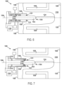
- Figure 5 shows an additional amount of the gas 310 entering the acceleration region 121 thereafter.
- a gas pressure adjacent to the one or more gas ports 116 within the acceleration region 121 might be within a range of 1000 to 5800 Torr (e.g ., 5450 to 5550 Torr) prior to the voltage between the inner electrode 102 and the outer electrode ( e.g ., the solid conductive shell 108) being applied via the power supply 118.
- the method 300 includes applying, via a power supply, a voltage between the inner electrode and the outer electrode, thereby converting at least a portion of the gas into a Z-pinch plasma that flows between (i) an electrically conductive material disposed on a solid conductive shell of the outer electrode and on the longitudinal axis of the plasma confinement system and (ii) the rounded first end of the inner electrode.
- the electrically conductive material has a melting point within a range of 170° C to 800° C ( e.g ., 180° C to 550 ° C) at 1 atmosphere of pressure.
- the power supply 118 can apply a voltage between the inner electrode 102 and the outer electrode (e.g ., the solid conductive shell 108), thereby converting at least a portion of the gas 310 into a Z-pinch plasma 318 (see Figures 8-9 ) that flows between (i) the electrically conductive material 110 disposed on the solid conductive shell 108 of the outer electrode and on the longitudinal axis 106 of the plasma confinement system 100 and (ii) the rounded first end 104 of the inner electrode 102.
- the outer electrode e.g ., the solid conductive shell 108
- the power supply 118 can apply the voltage between the inner electrode 102 and the solid conductive shell 108, thereby converting at least a portion of the gas 310 into a plasma 316 (see Figures 6-9 ) having a substantially annular cross section. Due to the magnetic field generated by its own current, the plasma 316 may flow axially within the acceleration region 121 toward the first end 104 of the inner electrode 102 and the first end 120 of the outer electrode as shown sequentially in Figures 6-9 .
- the Z-pinch plasma 318 is established in the assembly region 124 within the outer electrode between (i) the electrically conductive material 110 disposed on the solid conductive shell 108 of the outer electrode and on the longitudinal axis 106 of the plasma confinement system 100 and (ii) the rounded first end 104 of the inner electrode 102.
- the Z-pinch plasma 318 can exhibit sheared axial flow and have a radius between 0.1 mm and 5 mm, an ion temperature between 900 and 50,000 eV, an electron temperature greater than 500 eV ( e.g ., up to 50,000 eV), an ion number density greater than 1 ⁇ 10 23 ions/m 3 , an electron number density of greater than 1 ⁇ 10 23 electrons/m 3 , a magnetic field over 8 T, and/or may be stable for at least 10 ⁇ s.
- the method 300 includes moving a first liquid portion of the electrically conductive material out of the plasma confinement system.
- the first liquid portion of the electrically conductive material is heated via reaction products (e.g ., neutrons and other energetic particles) of the Z-pinch plasma.
- the heat exchanger 142 can receive ( e.g ., pump), via the second port 146, a portion of the electrically conductive material 110 that is heated within the plasma confinement system 100, extract heat from the electrically conductive material 110, and move ( e.g ., pump) the electrically conductive material 110 back into the pool region 140 via the first port 144 to be heated again by fusion reactions that take place in the plasma confinement system 100.
- the electrically conductive material 110 Prior to forming a plasma discharge within the plasma confinement system 100, the electrically conductive material 110 is generally heated ( e.g ., melted) into a liquid state using a ( e.g ., electric) heating element disposed within the plasma confinement system 100.
- the plasma confinement system 100 includes a feeding mechanism 112 (e.g. , an electromechanical system) that can move the inner electrode 102 in or out of the plasma confinement system 100 along the longitudinal axis 106.
- a feeding mechanism 112 e.g. , an electromechanical system
- the inner electrode 102 may become eroded by plasma discharge and the feeding mechanism 112 can be operated to feed in the inner electrode 102 to maintain the relative spacing between the inner electrode 102 and other components of the plasma confinement system 100.
- the pumps 150 and 156 can move or circulate the electrically conductive material 110 over the outer electrode (e.g ., over the solid conductive shell 108) so that different portions of the electrically conductive material 110 can be used to absorb current and/or heat (e.g ., at the longitudinal axis 106) from the Z-pinch plasma 318 over time.
- the electrically conductive material 110 will generally be in a liquid state.
- the pumps 150 and 156 move the electrically conductive material 110 such that the electrically conductive material 110 moved over the outer electrode ( e.g ., over the solid conductive shell 108) is moved in an azimuthal direction ( e.g ., into and/or out of the page) and/or an axial direction with respect to the longitudinal axis 106 of the plasma confinement system 100.
- the pumps 150 or 156 can move the electrically conductive material 110 from the pool region 140 to a region 152 that is outside the axial wall 136 and separated from the pool region 140 by the radial wall 138. Additionally, the pumps 150 or 156 can move the electrically conductive material 110 over the end 148 of the axial wall 136 to a region 154 inside the axial wall 136, and back toward the pool region 140.
- the voltage applied between the inner electrode 102 and the outer electrode is within a range of 2 kV to 30 kV.
- the voltage applied between the inner electrode and the outer electrode (e.g ., the solid conductive shell 108) can result in a radial electric field within a range of 30 kV/m to 500 kV/m.
- the Z-pinch plasma 318 has a radius between 0.1 mm and 5 mm, an ion temperature between 900 and 50,000 eV, and an electron temperature greater than 500 eV ( e.g ., up to 50,000 eV).
- the Z-pinch plasma 318 can have an ion number density greater than 1 ⁇ 10 23 ions/m 3 or an electron number density of greater than 1 ⁇ 10 23 electrons/m 3 , and can exhibit sheared flow with a magnetic field of over 8 T.
- the Z-pinch plasma 318 can exhibit stability for at least 10 ⁇ s.
- the reaction products of the Z-pinch plasma 318 include neutrons.
- neutrons and a portion of the electrically conductive material 110 can be consumed to generate additional tritium fuel for recovery at the heat exchanger 142.
- the reactive nature of the electrically conductive material 110 can also serve to reduce the base pressure within the plasma confinement system 100 by capturing vapor particles.
- Some embodiments include controlling a thickness of the electrically conductive material 110 on the solid conductive shell 108 by adjusting a rate at which the heat exchanger 142 moves the electrically conductive material 110 into the pool region 140 from the heat exchanger 142 or by adjusting a rate at which the electrically conductive material 110 moves to the heat exchanger 142 from the pool region 140.
- Increasing the rate at which the electrically conductive material 110 flows into the pool region 140 will generally increase the thickness of the electrically conductive material 110 on the solid conductive shell 108.
- Increasing the rate at which the electrically conductive material 110 flows out of the pool region 140 to the heat exchanger 142 will generally decrease the thickness of the electrically conductive material 110 on the solid conductive shell 108.
- Figure 10 is a block diagram of a method 1000 for operating a plasma confinement system (e.g ., the plasma confinement system 200).
- the plasma confinement system includes an inner electrode, an intermediate electrode that at least partially surrounds the inner electrode, and an outer electrode that at least partially surrounds the intermediate electrode.
- Figures 11-16 illustrate some of the aspects of the method 1000 as described below. Although Figures 11-16 show the longitudinal axis 206 of the plasma confinement system 200 aligned horizontally, in practice the longitudinal axis 206 generally will be aligned vertically
- the method 1000 includes flowing gas into an acceleration region between the inner electrode and the intermediate electrode.
- the one or more gas ports 216 can direct gas 310 (e.g ., one or more of tritium, deuterium, helium-3, hydrogen, a boron containing gas, or borane) into the acceleration region 221 between the inner electrode 202 and the intermediate electrode 205 that partially surrounds the inner electrode 202.
- gas 310 e.g ., one or more of tritium, deuterium, helium-3, hydrogen, a boron containing gas, or borane
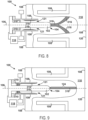
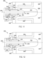
- Figure 11 shows an initial amount of the gas 310 entering the acceleration region 221
- Figure 12 shows an additional amount of the gas 310 entering the acceleration region 221 thereafter.
- a gas pressure adjacent to the one or more gas ports 216 within the acceleration region 221 might be within a range of 1000 to 5800 Torr (e.g ., 5450 to 5550 Torr) prior to the voltage between the inner electrode 202 and the intermediate electrode 205 being applied via the power supply 218.
- the method 1000 includes applying, via a first power supply, a voltage between the inner electrode and the intermediate electrode, thereby converting at least a portion of the gas into a plasma having a substantially annular cross section, the plasma flowing axially within the acceleration region toward a first end of the inner electrode and a first end of the outer electrode.
- the power supply 218 can apply a voltage between the inner electrode 202 and the intermediate electrode 205, thereby converting at least a portion of the gas 310 into a plasma 316 having a substantially annular cross section.
- the plasma 316 can flow axially within the acceleration region 221 toward a first end 204 of the inner electrode 202 and a first end 220 of the outer electrode. Due to the magnetic field generated by its own current, the plasma 316 can flow axially within the acceleration region 121 toward the first end 204 of the inner electrode 202 and the first end 220 of the outer electrode as shown sequentially in Figures 11-14 .
- the method 1000 includes applying, via a second power supply, a voltage between the inner electrode and the outer electrode to establish a Z-pinch plasma that flows between (i) an electrically conductive material disposed on a solid conductive shell of the outer electrode and (ii) the first end of the inner electrode.
- the electrically conductive material has a melting point within a range of 180° C to 800° C ( e.g ., 180° C to 550° C) at 1 atmosphere of pressure.
- the power supply 219 can apply a voltage between the inner electrode 202 and the outer electrode (e.g ., the solid conductive shell 208) to establish the Z-pinch plasma 318 that flows between (i) the electrically conductive material 210 disposed on the solid conductive shell 208 of the outer electrode and (ii) the first end 204 of the inner electrode 202.
- the electrically conductive material 210 has a melting point within a range of 180° C to 800° C ( e.g ., 180° C to 550° C) at 1 atmosphere of pressure.
- the Z-pinch plasma 318 is established in the assembly region 224 within the outer electrode between (i) the electrically conductive material 210 disposed on the solid conductive shell 208 of the outer electrode and on the longitudinal axis 206 of the plasma confinement system 200 and (ii) the rounded first end 204 of the inner electrode 202.
- the Z-pinch plasma 318 can exhibit sheared axial flow and have a radius between 0.1 mm and 5 mm, an ion temperature between 900 and 50,000 eV, an electron temperature greater than 500 eV ( e.g ., up to 50,000 eV), an ion number density greater than 1 ⁇ 10 23 ions/m 3 , an electron number density of greater than 1 ⁇ 10 23 electrons/m 3 , a magnetic field over 8 T, and/or may be stable for at least 10 ⁇ s.
- the method 1000 includes moving a first liquid portion of the electrically conductive material out of the plasma confinement system.
- the first liquid portion of the electrically conductive material is heated via reaction products of the Z-pinch plasma.
- the heat exchanger 242 can receive ( e.g ., pump), via the second port 246, a portion of the electrically conductive material 210 that is heated within the plasma confinement system 200, extract heat from the electrically conductive material 210, and move (e.g., pump) the electrically conductive material 210 back into the pool region 240 via the first port 244 to be heated again by fusion reactions that take place in the plasma confinement system 200.
- the electrically conductive material 210 Prior to forming a plasma discharge within the plasma confinement system 200, the electrically conductive material 210 is generally heated ( e.g ., melted) into a liquid state using a ( e.g ., electric) heating element disposed within the plasma confinement system 200.
- the plasma confinement system 200 includes a feeding mechanism 212 (e.g ., an electromechanical system) that can move the inner electrode 202 in or out of the plasma confinement system 200 along the longitudinal axis 206.
- a feeding mechanism 212 e.g ., an electromechanical system
- the inner electrode 202 may become eroded by plasma discharge and the feeding mechanism 212 can be operated to feed in the inner electrode 202 to maintain the relative spacing between the inner electrode 202 and other components of the plasma confinement system 200.
- the pumps 250 and 256 can move or circulate the electrically conductive material 210 over the outer electrode ( e.g ., over the solid conductive shell 208) so that different portions of the electrically conductive material 210 can be used to absorb current and/or heat (e.g ., at the longitudinal axis 206) from the Z-pinch plasma 318 over time.
- the electrically conductive material 210 will generally be in a liquid state.
- the pumps 250 and 256 move the electrically conductive material 210 such that the electrically conductive material 210 moved over the outer electrode ( e.g ., over the solid conductive shell 208) is moved in an azimuthal direction ( e.g ., into and/or out of the page) and/or an axial direction with respect to the longitudinal axis 206 of the plasma confinement system 100.
- the pumps 250 or 256 can move the electrically conductive material 210 from the pool region 240 to a region 252 that is outside the axial wall 236 and separated from the pool region 240 by the radial wall 238. Additionally, the pumps 250 or 256 can move the electrically conductive material 210 over the end 248 of the axial wall 236 to a region 254 inside the axial wall 236, and back toward the pool region 240.
- the voltage applied between the inner electrode 202 and the outer electrode (e.g ., the solid conductive shell 108) or between the inner electrode 202 and the intermediate electrode 205 is within a range of 2 kV to 30 kV.
- the voltage applied can result in electric fields within a range of 30 kV/m to 500 kV/m.
- the Z-pinch plasma 318 has a radius between 0.1 mm and 5 mm, an ion temperature between 900 and 50,000 eV, and an electron temperature greater than 500 eV ( e.g ., up to 50,000 eV).
- the Z-pinch plasma 318 can have an ion number density greater than 1 ⁇ 10 23 ions/m 3 or an electron number density of greater than 1 ⁇ 10 23 electrons/m 3 , and can exhibit sheared flow with a magnetic field of over 8 T.
- the Z-pinch plasma 318 can exhibit stability for at least 10 ⁇ s.
- the reaction products of the Z-pinch plasma 318 include neutrons.
- neutrons and a portion of the electrically conductive material 210 can be consumed to generate additional tritium fuel for recovery at the heat exchanger 242.
- the reactive nature of the electrically conductive material 210 can also serve to reduce the base pressure within the plasma confinement system 200 by capturing vapor particles.
- Some embodiments include controlling a thickness of the electrically conductive material 210 on the solid conductive shell 208 by adjusting a rate at which the heat exchanger 242 moves the electrically conductive material 210 into the pool region 240 from the heat exchanger 242 or by adjusting a rate at which the electrically conductive material 210 moves to the heat exchanger 242 from the pool region 240.
- Increasing the rate at which the electrically conductive material 210 flows into the pool region 240 will generally increase the thickness of the electrically conductive material 210 on the solid conductive shell 208.
- Increasing the rate at which the electrically conductive material 210 flows out of the pool region 240 to the heat exchanger 242 will generally decrease the thickness of the electrically conductive material 210 on the solid conductive shell 208.
Landscapes
- Physics & Mathematics (AREA)
- Engineering & Computer Science (AREA)
- Plasma & Fusion (AREA)
- Spectroscopy & Molecular Physics (AREA)
- General Engineering & Computer Science (AREA)
- High Energy & Nuclear Physics (AREA)
- Optics & Photonics (AREA)
- Power Engineering (AREA)
- Plasma Technology (AREA)
- Spark Plugs (AREA)
- Coating By Spraying Or Casting (AREA)
- Physical Or Chemical Processes And Apparatus (AREA)
Priority Applications (1)
| Application Number | Priority Date | Filing Date | Title |
|---|---|---|---|
| EP24170038.4A EP4376556A3 (en) | 2017-06-07 | 2018-06-07 | Plasma confinement system and methods for use |
Applications Claiming Priority (2)
| Application Number | Priority Date | Filing Date | Title |
|---|---|---|---|
| US201762516508P | 2017-06-07 | 2017-06-07 | |
| PCT/US2018/036388 WO2018226914A1 (en) | 2017-06-07 | 2018-06-07 | Plasma confinement system and methods for use |
Related Child Applications (2)
| Application Number | Title | Priority Date | Filing Date |
|---|---|---|---|
| EP24170038.4A Division EP4376556A3 (en) | 2017-06-07 | 2018-06-07 | Plasma confinement system and methods for use |
| EP24170038.4A Division-Into EP4376556A3 (en) | 2017-06-07 | 2018-06-07 | Plasma confinement system and methods for use |
Publications (4)
| Publication Number | Publication Date |
|---|---|
| EP3635748A1 EP3635748A1 (en) | 2020-04-15 |
| EP3635748A4 EP3635748A4 (en) | 2021-03-10 |
| EP3635748B1 true EP3635748B1 (en) | 2024-05-22 |
| EP3635748C0 EP3635748C0 (en) | 2024-05-22 |
Family
ID=64566330
Family Applications (2)
| Application Number | Title | Priority Date | Filing Date |
|---|---|---|---|
| EP18813105.6A Active EP3635748B1 (en) | 2017-06-07 | 2018-06-07 | Plasma confinement system and methods for use |
| EP24170038.4A Pending EP4376556A3 (en) | 2017-06-07 | 2018-06-07 | Plasma confinement system and methods for use |
Family Applications After (1)
| Application Number | Title | Priority Date | Filing Date |
|---|---|---|---|
| EP24170038.4A Pending EP4376556A3 (en) | 2017-06-07 | 2018-06-07 | Plasma confinement system and methods for use |
Country Status (13)
| Country | Link |
|---|---|
| US (2) | US11219117B2 (pl) |
| EP (2) | EP3635748B1 (pl) |
| JP (2) | JP7203768B2 (pl) |
| KR (2) | KR102697098B1 (pl) |
| CN (3) | CN110945599B (pl) |
| AU (1) | AU2018280166A1 (pl) |
| BR (1) | BR112019024844A2 (pl) |
| CA (2) | CA3264262A1 (pl) |
| EA (1) | EA201992371A1 (pl) |
| ES (1) | ES2979255T3 (pl) |
| IL (1) | IL271124A (pl) |
| PL (1) | PL3635748T3 (pl) |
| WO (1) | WO2018226914A1 (pl) |
Families Citing this family (13)
| Publication number | Priority date | Publication date | Assignee | Title |
|---|---|---|---|---|
| KR102778989B1 (ko) | 2017-02-23 | 2025-03-11 | 유니버시티 오브 워싱턴 | 플라즈마 감금 시스템 및 사용 방법 |
| AU2018280166A1 (en) * | 2017-06-07 | 2019-11-21 | Lawrence Livermore National Security, Llc. | Plasma confinement system and methods for use |
| US11515050B1 (en) * | 2019-11-22 | 2022-11-29 | X Development Llc | Mitigating plasma instability |
| CN113539524B (zh) * | 2020-04-15 | 2023-05-02 | 新奥科技发展有限公司 | 保持高性能等离子体的装置和方法 |
| CN116324267B (zh) | 2020-08-19 | 2024-05-14 | 大日本印刷株式会社 | 阻隔膜、以及使用了该阻隔膜的波长转换片、背光源和液晶显示装置、以及阻隔膜的选定方法 |
| JP6926309B1 (ja) | 2020-08-19 | 2021-08-25 | 大日本印刷株式会社 | バリアフィルム、並びに、これを用いた波長変換シート、バックライト及び液晶表示装置 |
| IL281747B2 (en) * | 2021-03-22 | 2024-04-01 | N T Tao Ltd | High efficiency plasma creation system and method |
| CA3216592A1 (en) * | 2021-05-28 | 2022-12-15 | Uri Shumlak | Apparatus and method for extended plasma confinement |
| JP2025504925A (ja) * | 2022-01-26 | 2025-02-19 | ザップ エナジー、インコーポレイテッド | Zピンチプラズマ閉じ込めシステムのための原位置での再生可能電極 |
| WO2023183597A1 (en) * | 2022-03-25 | 2023-09-28 | Fuse Energy Technologies Corp. | Plasma focus systems and methods for aneutronic fusion |
| CA3250956A1 (en) * | 2022-05-20 | 2023-11-23 | Zap Energy, Inc. | METHODS AND SYSTEMS FOR INCREASING ENERGY OUTPUT IN A Z-PINCH PLASMA CONFINEMENT SYSTEM |
| WO2023245062A2 (en) * | 2022-06-15 | 2023-12-21 | Fuse Energy Technologies Corp. | Multichannel plasma generation system and method |
| KR20250164271A (ko) * | 2023-03-22 | 2025-11-24 | 잽 에너지, 인크. | 플라즈마 밀폐 시스템에 사용하기 위한 합금 |
Family Cites Families (70)
| Publication number | Priority date | Publication date | Assignee | Title |
|---|---|---|---|---|
| US3029361A (en) * | 1958-08-19 | 1962-04-10 | Rca Corp | High temperature plasma confinement using a travelling electromagnetic field |
| DE1200447B (de) | 1964-03-05 | 1965-09-09 | Siemens Ag | Vorrichtung zur Erzeugung eines Plasmastrahles |
| US3265583A (en) | 1964-04-14 | 1966-08-09 | William R Baker | Apparatus for producing and purifying plasma |
| US3309873A (en) | 1964-08-31 | 1967-03-21 | Electro Optical Systems Inc | Plasma accelerator using hall currents |
| US3370198A (en) | 1967-06-21 | 1968-02-20 | Kenneth C. Rogers | Plasma accelerator having a cooled preionization chamber |
| US4042848A (en) | 1974-05-17 | 1977-08-16 | Ja Hyun Lee | Hypocycloidal pinch device |
| US4129772A (en) * | 1976-10-12 | 1978-12-12 | Wisconsin Alumni Research Foundation | Electrode structures for high energy high temperature plasmas |
| US4354999A (en) * | 1976-12-20 | 1982-10-19 | Priest Robert V | Plasma confinement |
| US4264413A (en) | 1976-12-22 | 1981-04-28 | General Atomic Company | Method and apparatus for high beta doublets and multiplets |
| US4244782A (en) * | 1977-10-25 | 1981-01-13 | Environmental Research Institute Of Michigan | Nuclear fusion system |
| US4260455A (en) * | 1978-03-14 | 1981-04-07 | The United States Of America As Represented By The Unites States Department Of Energy | Mirror plasma apparatus |
| US4406952A (en) | 1982-01-07 | 1983-09-27 | Molen George M | Opening switch for interrupting current using a plasma focus device |
| EP0202352A1 (de) * | 1985-05-22 | 1986-11-26 | C. CONRADTY NÜRNBERG GmbH & Co. KG | Plasmabrenner |
| JPS61274292A (ja) | 1985-05-29 | 1986-12-04 | 渡辺 健二 | 核融合実験装置 |
| US4734247A (en) | 1985-08-28 | 1988-03-29 | Ga Technologies Inc. | Helical shaping method and apparatus to produce large translational transform in pinch plasma magnetic confinement |
| US4663567A (en) | 1985-10-28 | 1987-05-05 | Physics International Company | Generation of stable linear plasmas |
| US4912731A (en) | 1987-04-13 | 1990-03-27 | Vittorio Nardi | Plasma focus apparatus with field distortion elements |
| NO174450C (no) * | 1991-12-12 | 1994-05-04 | Kvaerner Eng | Anordning ved plasmabrenner for kjemiske prosesser |
| NO174180C (no) * | 1991-12-12 | 1994-03-23 | Kvaerner Eng | Innföringsrör for brenner for kjemiske prosesser |
| JPH0817116B2 (ja) | 1992-12-24 | 1996-02-21 | 核融合科学研究所長 | プラズマ電磁加速器 |
| JPH08179066A (ja) | 1994-12-20 | 1996-07-12 | Mitsubishi Heavy Ind Ltd | プラズマ生成加速装置 |
| US6744060B2 (en) | 1997-05-12 | 2004-06-01 | Cymer, Inc. | Pulse power system for extreme ultraviolet and x-ray sources |
| US5763930A (en) * | 1997-05-12 | 1998-06-09 | Cymer, Inc. | Plasma focus high energy photon source |
| US6411666B1 (en) * | 1998-10-21 | 2002-06-25 | The United States Of America As Represented By The United States Department Of Energy | Method and apparatus to produce and maintain a thick, flowing, liquid lithium first wall for toroidal magnetic confinement DT fusion reactors |
| TWI246872B (en) | 1999-12-17 | 2006-01-01 | Asml Netherlands Bv | Radiation source for use in lithographic projection apparatus |
| JP4505664B2 (ja) | 2000-03-24 | 2010-07-21 | 株式会社ニコン | X線発生装置 |
| US7180081B2 (en) * | 2000-06-09 | 2007-02-20 | Cymer, Inc. | Discharge produced plasma EUV light source |
| RU2206186C2 (ru) * | 2000-07-04 | 2003-06-10 | Государственный научный центр Российской Федерации Троицкий институт инновационных и термоядерных исследований | Способ получения коротковолнового излучения из газоразрядной плазмы и устройство для его реализации |
| US6486593B1 (en) | 2000-09-29 | 2002-11-26 | The United States Of America As Represented By The United States Department Of Energy | Plasma accelerator |
| US6804327B2 (en) * | 2001-04-03 | 2004-10-12 | Lambda Physik Ag | Method and apparatus for generating high output power gas discharge based source of extreme ultraviolet radiation and/or soft x-rays |
| DE10219805B4 (de) | 2002-04-30 | 2013-03-14 | Xtreme Technologies Gmbh | Verfahren zur Stabilisierung der Strahlungsleistung einer gepuist betriebenen, auf gasentladungserzeugtem Plasma basierenden Strahlungsquelle |
| AU2003233772A1 (en) | 2002-05-24 | 2003-12-12 | Sig Technology Ltd. | Method and device for plasma treating workpieces |
| ATE341186T1 (de) * | 2002-08-14 | 2006-10-15 | Ltd Company Sproton 21S | Verfahren und vorrichtung zum schlag-verdichten eines stoffes und plasmakathode dazu |
| JP2004226244A (ja) | 2003-01-23 | 2004-08-12 | Ushio Inc | 極端紫外光源および半導体露光装置 |
| AU2004222932B2 (en) | 2003-03-21 | 2011-04-28 | Utah State University | Systems and methods for plasma containment |
| US7307375B2 (en) | 2004-07-09 | 2007-12-11 | Energetiq Technology Inc. | Inductively-driven plasma light source |
| US7501765B2 (en) * | 2004-10-01 | 2009-03-10 | Illinois Tool Works Inc. | Emitter electrodes formed of chemical vapor deposition silicon carbide |
| US7679025B1 (en) | 2005-02-04 | 2010-03-16 | Mahadevan Krishnan | Dense plasma focus apparatus |
| US20060198486A1 (en) * | 2005-03-04 | 2006-09-07 | Laberge Michel G | Pressure wave generator and controller for generating a pressure wave in a fusion reactor |
| US7115887B1 (en) | 2005-03-15 | 2006-10-03 | The United States Of America As Represented By The United States Department Of Energy | Method for generating extreme ultraviolet with mather-type plasma accelerators for use in Extreme Ultraviolet Lithography |
| DE102005020521B4 (de) | 2005-04-29 | 2013-05-02 | Xtreme Technologies Gmbh | Verfahren und Anordnung zur Unterdrückung von Debris bei der Erzeugung kurzwelliger Strahlung auf Basis eines Plasmas |
| DE102005025624B4 (de) | 2005-06-01 | 2010-03-18 | Xtreme Technologies Gmbh | Anordnung zur Erzeugung von intensiver kurzwelliger Strahlung auf Basis eines Gasentladungsplasmas |
| WO2006131975A1 (ja) | 2005-06-09 | 2006-12-14 | Tetsu Miyamoto | ベースボールzピンチによる高温高密度プラズマ柱、その生成方法及び生成装置 |
| US7372059B2 (en) | 2005-10-17 | 2008-05-13 | The University Of Washington | Plasma-based EUV light source |
| US9036765B2 (en) | 2006-05-30 | 2015-05-19 | Advanced Fusion Systems Llc | Method and system for inertial confinement fusion reactions |
| JP2008071611A (ja) * | 2006-09-14 | 2008-03-27 | Sekisui Chem Co Ltd | プラズマ表面処理装置の電極構造 |
| US7838853B2 (en) | 2006-12-14 | 2010-11-23 | Asml Netherlands B.V. | Plasma radiation source, method of forming plasma radiation, apparatus for projecting a pattern from a patterning device onto a substrate and device manufacturing method |
| US8537958B2 (en) | 2009-02-04 | 2013-09-17 | General Fusion, Inc. | Systems and methods for compressing plasma |
| US9560734B2 (en) | 2009-02-20 | 2017-01-31 | Lawrence Livermore National Security, Llc | Dense plasma focus (DPF) accelerated non radio isotopic radiological source |
| CA2767904C (en) | 2009-07-29 | 2014-10-14 | General Fusion, Inc. | Systems and methods for plasma compression with recycling of projectiles |
| DE102010023339A1 (de) * | 2010-06-10 | 2011-12-15 | Siemens Aktiengesellschaft | Beschleuniger für zwei Teilchenstrahlen zum Erzeugen einer Kollision |
| CA2854823C (en) * | 2011-11-07 | 2020-04-14 | Helion Energy, Inc. | Apparatus, systems and methods for fusion based power generation and engine thrust generation |
| US20150302940A1 (en) * | 2011-11-09 | 2015-10-22 | University Of Washington Through Its Center For Commercialization | Electromagnetic Matter Injector and Capsule System |
| US9123500B2 (en) * | 2012-03-31 | 2015-09-01 | Fei Company | Automated ion beam idle |
| JP5965052B2 (ja) | 2012-04-04 | 2016-08-03 | ジェネラル フュージョン インコーポレイテッド | ジェット制御デバイス及び方法 |
| US9596745B2 (en) * | 2012-08-29 | 2017-03-14 | General Fusion Inc. | Apparatus for accelerating and compressing plasma |
| US9934876B2 (en) * | 2013-04-03 | 2018-04-03 | Lockheed Martin Corporation | Magnetic field plasma confinement for compact fusion power |
| AU2014302152A1 (en) * | 2013-06-27 | 2016-02-18 | Nonlinear Ion Dynamics, Llc. | Methods, devices and systems for fusion reactions |
| JP6342251B2 (ja) * | 2014-07-25 | 2018-06-13 | 国立大学法人北海道大学 | 酸化タングステン及び金属タングステン微粒子の製造方法とそれにより得られる微粒子 |
| US10811155B2 (en) * | 2017-01-31 | 2020-10-20 | The Boeing Company | Plasma pinch neutron generators and methods of generating neutrons |
| JP6732670B2 (ja) | 2017-02-01 | 2020-07-29 | 株式会社東芝 | 核融合炉用ブランケット、ブランケット支持構造、筐体壁内冷却水流路の形成方法、ブランケットモジュール組み立て方法およびブランケット支持構造組み立て方法 |
| KR102778989B1 (ko) * | 2017-02-23 | 2025-03-11 | 유니버시티 오브 워싱턴 | 플라즈마 감금 시스템 및 사용 방법 |
| US10204765B2 (en) | 2017-05-25 | 2019-02-12 | Pear Labs Llc | Non-thermal plasma gate device |
| AU2018280166A1 (en) * | 2017-06-07 | 2019-11-21 | Lawrence Livermore National Security, Llc. | Plasma confinement system and methods for use |
| US10811144B2 (en) * | 2017-11-06 | 2020-10-20 | General Fusion Inc. | System and method for plasma generation and compression |
| US11515050B1 (en) | 2019-11-22 | 2022-11-29 | X Development Llc | Mitigating plasma instability |
| CA3216592A1 (en) | 2021-05-28 | 2022-12-15 | Uri Shumlak | Apparatus and method for extended plasma confinement |
| JP2025504925A (ja) * | 2022-01-26 | 2025-02-19 | ザップ エナジー、インコーポレイテッド | Zピンチプラズマ閉じ込めシステムのための原位置での再生可能電極 |
| CA3250956A1 (en) | 2022-05-20 | 2023-11-23 | Zap Energy, Inc. | METHODS AND SYSTEMS FOR INCREASING ENERGY OUTPUT IN A Z-PINCH PLASMA CONFINEMENT SYSTEM |
| KR20250164271A (ko) | 2023-03-22 | 2025-11-24 | 잽 에너지, 인크. | 플라즈마 밀폐 시스템에 사용하기 위한 합금 |
-
2018
- 2018-06-07 AU AU2018280166A patent/AU2018280166A1/en not_active Abandoned
- 2018-06-07 ES ES18813105T patent/ES2979255T3/es active Active
- 2018-06-07 US US16/619,895 patent/US11219117B2/en active Active
- 2018-06-07 EA EA201992371A patent/EA201992371A1/ru unknown
- 2018-06-07 KR KR1020237030734A patent/KR102697098B1/ko active Active
- 2018-06-07 EP EP18813105.6A patent/EP3635748B1/en active Active
- 2018-06-07 CA CA3264262A patent/CA3264262A1/en active Pending
- 2018-06-07 EP EP24170038.4A patent/EP4376556A3/en active Pending
- 2018-06-07 PL PL18813105.6T patent/PL3635748T3/pl unknown
- 2018-06-07 CA CA3064769A patent/CA3064769A1/en active Pending
- 2018-06-07 CN CN201880034323.9A patent/CN110945599B/zh active Active
- 2018-06-07 CN CN202311213702.3A patent/CN117352196A/zh active Pending
- 2018-06-07 BR BR112019024844-7A patent/BR112019024844A2/pt not_active IP Right Cessation
- 2018-06-07 CN CN202311216551.7A patent/CN117334356A/zh active Pending
- 2018-06-07 JP JP2019566613A patent/JP7203768B2/ja active Active
- 2018-06-07 WO PCT/US2018/036388 patent/WO2018226914A1/en not_active Ceased
- 2018-06-07 KR KR1020197037179A patent/KR102578149B1/ko active Active
-
2019
- 2019-12-02 IL IL271124A patent/IL271124A/en unknown
-
2021
- 2021-11-29 US US17/536,487 patent/US12610447B2/en active Active
-
2022
- 2022-12-27 JP JP2022209618A patent/JP7458472B2/ja active Active
Non-Patent Citations (2)
| Title |
|---|
| MCLEAN HARRY S ET AL: "Development of a Compact Fusion Device based on the Flow Z-Pinch", 2016 ARPA-E ANNUAL REVIEW, 11 August 2015 (2015-08-11), pages 1 - 36, XP055966807, Retrieved from the Internet <URL:https://arpa-e.energy.gov/sites/default/files/MCLEAN_Reduced_2016.pdf> [retrieved on 20220930] * |
| U. SHUMLAK ET AL: "High energy density Z-pinch plasmas using flow stabilization", AIP CONFERENCE PROCEEDINGS, vol. 1639, 1 January 2014 (2014-01-01), NEW YORK, US, pages 76 - 79, XP055533092, ISSN: 0094-243X, DOI: 10.1063/1.4904781 * |
Also Published As
| Publication number | Publication date |
|---|---|
| AU2018280166A1 (en) | 2019-11-21 |
| ES2979255T3 (es) | 2024-09-25 |
| IL271124A (en) | 2020-01-30 |
| EA201992371A1 (ru) | 2020-04-03 |
| JP2023030156A (ja) | 2023-03-07 |
| CA3064769A1 (en) | 2018-12-13 |
| CN117352196A (zh) | 2024-01-05 |
| CN110945599B (zh) | 2023-10-10 |
| PL3635748T3 (pl) | 2024-07-29 |
| JP7203768B2 (ja) | 2023-01-13 |
| EP4376556A3 (en) | 2024-10-23 |
| JP2020523734A (ja) | 2020-08-06 |
| CA3264262A1 (en) | 2025-03-15 |
| BR112019024844A2 (pt) | 2020-06-09 |
| CN110945599A (zh) | 2020-03-31 |
| US20220117072A1 (en) | 2022-04-14 |
| US11219117B2 (en) | 2022-01-04 |
| EP3635748A4 (en) | 2021-03-10 |
| EP3635748C0 (en) | 2024-05-22 |
| EP4376556A2 (en) | 2024-05-29 |
| CN117334356A (zh) | 2024-01-02 |
| WO2018226914A1 (en) | 2018-12-13 |
| KR20230132634A (ko) | 2023-09-15 |
| US12610447B2 (en) | 2026-04-21 |
| KR102697098B1 (ko) | 2024-08-21 |
| KR102578149B1 (ko) | 2023-09-20 |
| JP7458472B2 (ja) | 2024-03-29 |
| EP3635748A1 (en) | 2020-04-15 |
| US20200168350A1 (en) | 2020-05-28 |
| KR20200019141A (ko) | 2020-02-21 |
Similar Documents
| Publication | Publication Date | Title |
|---|---|---|
| EP3635748B1 (en) | Plasma confinement system and methods for use | |
| US12245351B2 (en) | Plasma confinement system | |
| KR102823906B1 (ko) | 상호 작용하는 반응물에 대한 쿨롱 장벽 감소 | |
| Kelley et al. | Neutral-beam-injection heating of toroidal plasmas for fusion research | |
| HK40104081A (zh) | 等离子体约束系统及使用方法 | |
| US4218633A (en) | Hydrogen hollow cathode ion source | |
| HK40104772A (zh) | 等离子体约束系统及使用方法 | |
| HK40025354A (en) | Plasma confinement system and methods for use | |
| HK40025354B (zh) | 等离子体约束系统及使用方法 | |
| EA041312B1 (ru) | Система удержания плазмы | |
| CN113643950B (zh) | 一种产生掺杂碱金属或卤素的耦合气体团簇离子束的装置和方法 | |
| US3452249A (en) | Method and apparatus for containing a plasma produced by opposed electrodes | |
| RU2401521C1 (ru) | Ускоритель плазмы с замкнутым холловским током (варианты) | |
| Kugel et al. | Development of lithium deposition techniques for TFTR | |
| WO2026064411A1 (en) | Partial ionization plasma centrifuge for fusion power | |
| Emigh | Tritium ion beam for an intense neutron source, INS | |
| Degnan et al. | Full axial coverage radiography of deformable contact liner implosion performed with 8 cm diameter electrode apertures | |
| JPH0218900A (ja) | イオンダンプ | |
| Watson et al. | Technical considerations in the design of the Chalk River high temperature helium‐jet ion source | |
| US20150270020A1 (en) | Device for creating nuclear fusion |
Legal Events
| Date | Code | Title | Description |
|---|---|---|---|
| STAA | Information on the status of an ep patent application or granted ep patent |
Free format text: STATUS: THE INTERNATIONAL PUBLICATION HAS BEEN MADE |
|
| PUAI | Public reference made under article 153(3) epc to a published international application that has entered the european phase |
Free format text: ORIGINAL CODE: 0009012 |
|
| STAA | Information on the status of an ep patent application or granted ep patent |
Free format text: STATUS: REQUEST FOR EXAMINATION WAS MADE |
|
| 17P | Request for examination filed |
Effective date: 20191118 |
|
| AK | Designated contracting states |
Kind code of ref document: A1 Designated state(s): AL AT BE BG CH CY CZ DE DK EE ES FI FR GB GR HR HU IE IS IT LI LT LU LV MC MK MT NL NO PL PT RO RS SE SI SK SM TR |
|
| AX | Request for extension of the european patent |
Extension state: BA ME |
|
| DAV | Request for validation of the european patent (deleted) | ||
| DAX | Request for extension of the european patent (deleted) | ||
| A4 | Supplementary search report drawn up and despatched |
Effective date: 20210210 |
|
| RIC1 | Information provided on ipc code assigned before grant |
Ipc: G21B 1/05 20060101AFI20210204BHEP Ipc: H05H 1/06 20060101ALI20210204BHEP Ipc: G21B 1/11 20060101ALI20210204BHEP |
|
| STAA | Information on the status of an ep patent application or granted ep patent |
Free format text: STATUS: EXAMINATION IS IN PROGRESS |
|
| 17Q | First examination report despatched |
Effective date: 20221007 |
|
| P01 | Opt-out of the competence of the unified patent court (upc) registered |
Effective date: 20230524 |
|
| GRAP | Despatch of communication of intention to grant a patent |
Free format text: ORIGINAL CODE: EPIDOSNIGR1 |
|
| STAA | Information on the status of an ep patent application or granted ep patent |
Free format text: STATUS: GRANT OF PATENT IS INTENDED |
|
| INTG | Intention to grant announced |
Effective date: 20230705 |
|
| GRAJ | Information related to disapproval of communication of intention to grant by the applicant or resumption of examination proceedings by the epo deleted |
Free format text: ORIGINAL CODE: EPIDOSDIGR1 |
|
| STAA | Information on the status of an ep patent application or granted ep patent |
Free format text: STATUS: EXAMINATION IS IN PROGRESS |
|
| GRAP | Despatch of communication of intention to grant a patent |
Free format text: ORIGINAL CODE: EPIDOSNIGR1 |
|
| STAA | Information on the status of an ep patent application or granted ep patent |
Free format text: STATUS: GRANT OF PATENT IS INTENDED |
|
| INTC | Intention to grant announced (deleted) | ||
| INTG | Intention to grant announced |
Effective date: 20231212 |
|
| RIN1 | Information on inventor provided before grant (corrected) |
Inventor name: NELSON, BRIAN A. Inventor name: MCLEAN, HARRY S. Inventor name: SHUMLAK, URI |
|
| GRAS | Grant fee paid |
Free format text: ORIGINAL CODE: EPIDOSNIGR3 |
|
| GRAA | (expected) grant |
Free format text: ORIGINAL CODE: 0009210 |
|
| STAA | Information on the status of an ep patent application or granted ep patent |
Free format text: STATUS: THE PATENT HAS BEEN GRANTED |
|
| AK | Designated contracting states |
Kind code of ref document: B1 Designated state(s): AL AT BE BG CH CY CZ DE DK EE ES FI FR GB GR HR HU IE IS IT LI LT LU LV MC MK MT NL NO PL PT RO RS SE SI SK SM TR |
|
| REG | Reference to a national code |
Ref country code: GB Ref legal event code: FG4D |
|
| REG | Reference to a national code |
Ref country code: CH Ref legal event code: EP |
|
| REG | Reference to a national code |
Ref country code: DE Ref legal event code: R096 Ref document number: 602018069836 Country of ref document: DE |
|
| REG | Reference to a national code |
Ref country code: IE Ref legal event code: FG4D |
|
| PGFP | Annual fee paid to national office [announced via postgrant information from national office to epo] |
Ref country code: IE Payment date: 20240620 Year of fee payment: 7 |
|
| U01 | Request for unitary effect filed |
Effective date: 20240605 |
|
| PGFP | Annual fee paid to national office [announced via postgrant information from national office to epo] |
Ref country code: NL Payment date: 20240619 Year of fee payment: 7 |
|
| PGFP | Annual fee paid to national office [announced via postgrant information from national office to epo] |
Ref country code: AT Payment date: 20240620 Year of fee payment: 7 |
|
| P04 | Withdrawal of opt-out of the competence of the unified patent court (upc) registered |
Free format text: CASE NUMBER: APP_36279/2024 Effective date: 20240617 |
|
| U07 | Unitary effect registered |
Designated state(s): AT BE BG DE DK EE FI FR IT LT LU LV MT NL PT SE SI Effective date: 20240620 |
|
| U20 | Renewal fee for the european patent with unitary effect paid |
Year of fee payment: 7 Effective date: 20240628 |
|
| REG | Reference to a national code |
Ref country code: ES Ref legal event code: FG2A Ref document number: 2979255 Country of ref document: ES Kind code of ref document: T3 Effective date: 20240925 |
|
| PG25 | Lapsed in a contracting state [announced via postgrant information from national office to epo] |
Ref country code: IS Free format text: LAPSE BECAUSE OF FAILURE TO SUBMIT A TRANSLATION OF THE DESCRIPTION OR TO PAY THE FEE WITHIN THE PRESCRIBED TIME-LIMIT Effective date: 20240922 |
|
| PG25 | Lapsed in a contracting state [announced via postgrant information from national office to epo] |
Ref country code: HR Free format text: LAPSE BECAUSE OF FAILURE TO SUBMIT A TRANSLATION OF THE DESCRIPTION OR TO PAY THE FEE WITHIN THE PRESCRIBED TIME-LIMIT Effective date: 20240522 |
|
| PG25 | Lapsed in a contracting state [announced via postgrant information from national office to epo] |
Ref country code: GR Free format text: LAPSE BECAUSE OF FAILURE TO SUBMIT A TRANSLATION OF THE DESCRIPTION OR TO PAY THE FEE WITHIN THE PRESCRIBED TIME-LIMIT Effective date: 20240823 |
|
| PGFP | Annual fee paid to national office [announced via postgrant information from national office to epo] |
Ref country code: PL Payment date: 20240619 Year of fee payment: 7 |
|
| PG25 | Lapsed in a contracting state [announced via postgrant information from national office to epo] |
Ref country code: IS Free format text: LAPSE BECAUSE OF FAILURE TO SUBMIT A TRANSLATION OF THE DESCRIPTION OR TO PAY THE FEE WITHIN THE PRESCRIBED TIME-LIMIT Effective date: 20240922 Ref country code: HR Free format text: LAPSE BECAUSE OF FAILURE TO SUBMIT A TRANSLATION OF THE DESCRIPTION OR TO PAY THE FEE WITHIN THE PRESCRIBED TIME-LIMIT Effective date: 20240522 Ref country code: GR Free format text: LAPSE BECAUSE OF FAILURE TO SUBMIT A TRANSLATION OF THE DESCRIPTION OR TO PAY THE FEE WITHIN THE PRESCRIBED TIME-LIMIT Effective date: 20240823 Ref country code: RS Free format text: LAPSE BECAUSE OF FAILURE TO SUBMIT A TRANSLATION OF THE DESCRIPTION OR TO PAY THE FEE WITHIN THE PRESCRIBED TIME-LIMIT Effective date: 20240822 |
|
| P05 | Withdrawal of opt-out of the competence of the unified patent court (upc) changed |
Free format text: CASE NUMBER: APP_36279/2024 Effective date: 20240620 |
|
| PG25 | Lapsed in a contracting state [announced via postgrant information from national office to epo] |
Ref country code: RO Free format text: LAPSE BECAUSE OF FAILURE TO SUBMIT A TRANSLATION OF THE DESCRIPTION OR TO PAY THE FEE WITHIN THE PRESCRIBED TIME-LIMIT Effective date: 20240522 Ref country code: SK Free format text: LAPSE BECAUSE OF FAILURE TO SUBMIT A TRANSLATION OF THE DESCRIPTION OR TO PAY THE FEE WITHIN THE PRESCRIBED TIME-LIMIT Effective date: 20240522 |
|
| PG25 | Lapsed in a contracting state [announced via postgrant information from national office to epo] |
Ref country code: SM Free format text: LAPSE BECAUSE OF FAILURE TO SUBMIT A TRANSLATION OF THE DESCRIPTION OR TO PAY THE FEE WITHIN THE PRESCRIBED TIME-LIMIT Effective date: 20240522 |
|
| PG25 | Lapsed in a contracting state [announced via postgrant information from national office to epo] |
Ref country code: SM Free format text: LAPSE BECAUSE OF FAILURE TO SUBMIT A TRANSLATION OF THE DESCRIPTION OR TO PAY THE FEE WITHIN THE PRESCRIBED TIME-LIMIT Effective date: 20240522 Ref country code: SK Free format text: LAPSE BECAUSE OF FAILURE TO SUBMIT A TRANSLATION OF THE DESCRIPTION OR TO PAY THE FEE WITHIN THE PRESCRIBED TIME-LIMIT Effective date: 20240522 Ref country code: RO Free format text: LAPSE BECAUSE OF FAILURE TO SUBMIT A TRANSLATION OF THE DESCRIPTION OR TO PAY THE FEE WITHIN THE PRESCRIBED TIME-LIMIT Effective date: 20240522 |
|
| PG25 | Lapsed in a contracting state [announced via postgrant information from national office to epo] |
Ref country code: MC Free format text: LAPSE BECAUSE OF FAILURE TO SUBMIT A TRANSLATION OF THE DESCRIPTION OR TO PAY THE FEE WITHIN THE PRESCRIBED TIME-LIMIT Effective date: 20240522 |
|
| REG | Reference to a national code |
Ref country code: DE Ref legal event code: R097 Ref document number: 602018069836 Country of ref document: DE |
|
| PLBE | No opposition filed within time limit |
Free format text: ORIGINAL CODE: 0009261 |
|
| STAA | Information on the status of an ep patent application or granted ep patent |
Free format text: STATUS: NO OPPOSITION FILED WITHIN TIME LIMIT |
|
| 26N | No opposition filed |
Effective date: 20250225 |
|
| U20 | Renewal fee for the european patent with unitary effect paid |
Year of fee payment: 8 Effective date: 20250520 |
|
| PGFP | Annual fee paid to national office [announced via postgrant information from national office to epo] |
Ref country code: GB Payment date: 20250520 Year of fee payment: 8 |
|
| PGFP | Annual fee paid to national office [announced via postgrant information from national office to epo] |
Ref country code: NO Payment date: 20250522 Year of fee payment: 8 |
|
| PGFP | Annual fee paid to national office [announced via postgrant information from national office to epo] |
Ref country code: CZ Payment date: 20250528 Year of fee payment: 8 |
|
| PGFP | Annual fee paid to national office [announced via postgrant information from national office to epo] |
Ref country code: ES Payment date: 20250701 Year of fee payment: 8 |
|
| PGFP | Annual fee paid to national office [announced via postgrant information from national office to epo] |
Ref country code: CH Payment date: 20250701 Year of fee payment: 8 |
|
| PG25 | Lapsed in a contracting state [announced via postgrant information from national office to epo] |
Ref country code: CY Free format text: LAPSE BECAUSE OF FAILURE TO SUBMIT A TRANSLATION OF THE DESCRIPTION OR TO PAY THE FEE WITHIN THE PRESCRIBED TIME-LIMIT; INVALID AB INITIO Effective date: 20180607 |
|
| PGFP | Annual fee paid to national office [announced via postgrant information from national office to epo] |
Ref country code: BE Payment date: 20240619 Year of fee payment: 7 |
|
| PG25 | Lapsed in a contracting state [announced via postgrant information from national office to epo] |
Ref country code: HU Free format text: LAPSE BECAUSE OF FAILURE TO SUBMIT A TRANSLATION OF THE DESCRIPTION OR TO PAY THE FEE WITHIN THE PRESCRIBED TIME-LIMIT; INVALID AB INITIO Effective date: 20180607 |
|
| PG25 | Lapsed in a contracting state [announced via postgrant information from national office to epo] |
Ref country code: IE Free format text: LAPSE BECAUSE OF NON-PAYMENT OF DUE FEES Effective date: 20250607 |