EP3636092A1 - Helm - Google Patents
Helm Download PDFInfo
- Publication number
- EP3636092A1 EP3636092A1 EP18806345.7A EP18806345A EP3636092A1 EP 3636092 A1 EP3636092 A1 EP 3636092A1 EP 18806345 A EP18806345 A EP 18806345A EP 3636092 A1 EP3636092 A1 EP 3636092A1
- Authority
- EP
- European Patent Office
- Prior art keywords
- liner
- helmet
- main body
- insert
- recessed portion
- Prior art date
- Legal status (The legal status is an assumption and is not a legal conclusion. Google has not performed a legal analysis and makes no representation as to the accuracy of the status listed.)
- Granted
Links
Images





Classifications
-
- A—HUMAN NECESSITIES
- A42—HEADWEAR
- A42B—HATS; HEAD COVERINGS
- A42B3/00—Helmets; Helmet covers ; Other protective head coverings
- A42B3/04—Parts, details or accessories of helmets
- A42B3/10—Linings
- A42B3/12—Cushioning devices
-
- A—HUMAN NECESSITIES
- A42—HEADWEAR
- A42B—HATS; HEAD COVERINGS
- A42B3/00—Helmets; Helmet covers ; Other protective head coverings
- A42B3/04—Parts, details or accessories of helmets
- A42B3/06—Impact-absorbing shells, e.g. of crash helmets
-
- A—HUMAN NECESSITIES
- A42—HEADWEAR
- A42B—HATS; HEAD COVERINGS
- A42B3/00—Helmets; Helmet covers ; Other protective head coverings
- A42B3/04—Parts, details or accessories of helmets
- A42B3/06—Impact-absorbing shells, e.g. of crash helmets
- A42B3/062—Impact-absorbing shells, e.g. of crash helmets with reinforcing means
- A42B3/063—Impact-absorbing shells, e.g. of crash helmets with reinforcing means using layered structures
- A42B3/064—Impact-absorbing shells, e.g. of crash helmets with reinforcing means using layered structures with relative movement between layers
-
- A—HUMAN NECESSITIES
- A42—HEADWEAR
- A42B—HATS; HEAD COVERINGS
- A42B3/00—Helmets; Helmet covers ; Other protective head coverings
- A42B3/04—Parts, details or accessories of helmets
- A42B3/10—Linings
- A42B3/12—Cushioning devices
- A42B3/125—Cushioning devices with a padded structure, e.g. foam
- A42B3/127—Cushioning devices with a padded structure, e.g. foam with removable or adjustable pads
-
- A—HUMAN NECESSITIES
- A42—HEADWEAR
- A42B—HATS; HEAD COVERINGS
- A42B3/00—Helmets; Helmet covers ; Other protective head coverings
- A42B3/04—Parts, details or accessories of helmets
- A42B3/28—Ventilating arrangements
-
- A—HUMAN NECESSITIES
- A42—HEADWEAR
- A42B—HATS; HEAD COVERINGS
- A42B3/00—Helmets; Helmet covers ; Other protective head coverings
- A42B3/04—Parts, details or accessories of helmets
- A42B3/28—Ventilating arrangements
- A42B3/281—Air ducting systems
Definitions
- the present invention relates to a helmet having an outer shell comprising a hard material and a shock absorbing liner disposed inside the outer shell.
- Safety helmets such as open face helmets and full face helmets for example, are conventionally known as helmets that riders of motorcycles, for example, put on to protect their heads.
- Such conventional helmets are mainly configured from an outer shell and, disposed inside the shell, a shock absorbing liner, a right and left pair of chin straps, and internal padding for improving the comfort of the wearer.
- through holes for ventilation are provided at the upper portion of a facial opening provided in the front face of the helmet to ensure a field of view for the wearer.
- the shell When a region of part of the outer shell is impacted, the shell functions to disperse the impact to a wider region and absorb the impact energy through deformation. Furthermore, the shock absorbing liner functions to absorb, through a reduction in its thickness (i.e., compression), the impact energy propagated from the outer shell and delay the propagation of the impact energy to the wearer's head to thereby reduce the maximum acceleration resulting from the impact.
- maximum acceleration means the maximum value of acceleration obtained by an "impact absorption test" of the helmet.
- an "impact absorption test” is performed.
- a model head made of metal is used as a model of the helmet wearer's head.
- the impact applied to the helmet in the “impact absorption test” is absorbed as described above, and maximum acceleration is measured by an accelerometer disposed inside the model head made of metal as the impact force that finally propagated to the head.
- the method of the "impact absorption test” and the standard value for maximum acceleration are respectively determined by respective countries.
- Japanese Patent No. 3,825,106 discloses a structure where a cavity portion is provided in the top portion of the inside of a shock absorbing liner and a separate member is inserted into the cavity portion.
- the inserted member (called an insert liner) has a smaller density, that is, is softer than the shock absorbing liner, so it can reduce the rigidity of the top portion. In this way, the impact absorbability of the top portion can be maintained.
- Diffuse axonal injury is an injury where axons in the brain become sheared and trauma develops as a result of the brain being violently shaken.
- the mechanism by which a diffuse axonal injury occurs in the head of a rider is described as follows.
- the rotational acceleration produced by the impact propagates to the wearer's head.
- the wearer's head also stops rotating at the same time as the helmet.
- rotational force acts on the brain floating in the cerebrospinal fluid, and axons interconnecting the brain and the interior of the cranium become sheared.
- a helmet of a first aspect is a helmet comprising an outer shell configured by a hard material, and a shock absorbing liner disposed inside the outer shell, wherein the shock absorbing liner comprises a main body liner, a recessed portion provided at an inner surface of the main body liner, an insert liner fitted into the recessed portion, and a central support member disposed between a bottom surface of the recessed portion and a bottom surface of the insert liner.
- an impact to the outer shell is absorbed by the shock absorbing liner disposed inside the outer shell becoming deformed.
- the insert liner is fitted into the recessed portion of the main body liner.
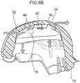
- the central support member becomes compressively deformed by the impact, and the insert liner tilts. That is, the insert liner moves with respect to the main body liner.
- the wearer's head in close contact with the insert liner also moves together with the insert liner, so rotational acceleration does not propagate to the inside of the head.
- volume of the insert liner is reduced rather than density being reduced as in the insert liner of the conventional example, so the same effects as those of the conventional insert liner are obtained. In this way, not only rotational acceleration of the wearer's head but also translational acceleration can be effectively reduced.
- a helmet of a second aspect is the helmet of the first aspect, wherein the shock absorbing liner has a plurality of other support members disposed around the central support member.
- the support members support the insert liner together with the central support member, so the helmet can be worn in a stable state without the insert liner tilting and the helmet wobbling.
- a helmet of a third aspect is the helmet of the first aspect or the second aspect, wherein the central support member is molded integrally with the insert liner.
- the central support member is molded integrally with the insert liner, so the number of constituent parts of the helmet can be inhibited from increasing.
- a helmet of a fourth aspect is the helmet of the second aspect or the third aspect, wherein the cross-sectional area of respective distal end of the other support members is smaller than the cross-sectional area of a distal end of the central support member, and the central support member and the other support members are molded integrally with the insert liner.
- the central support member and the other support members are molded integrally with the insert liner, so the number of constituent parts of the helmet can be inhibited from increasing. Furthermore, when the force of impact travels from the bottom surface of the recessed portion to the central support member and the other support members, the other support members with the smaller contact area become deformed or break first, so the central support member can be prevented from being completely destroyed by the impact. In this way, tilting of the insert liner by the central support member can be reliably carried out.
- a helmet of a fifth aspect is the helmet of any one of the first aspect to the fourth aspect, wherein a ventilation passage that communicates with an air inlet at a front side of the helmet and a ventilation passage that communicates with an air outlet at a back side of the helmet are provided at the recessed portion, and a ventilation passage that communicates the recessed portion with the inner surface of the main body liner is provided at the insert liner, the inner surface being configured to contact a head region of a wearer,.
- outside air taken in through the air inlet at the front face of the helmet is guided to the recessed portion of the main body liner and reaches the air outlet at the back side from the recessed portion. Because of this flow of air, heat emanating from the wearer's head is guided from the inner surface of the main body liner through the ventilation passage of the insert liner to the recessed portion. Furthermore, the outside air in the recessed portion goes to the inner surface of the main body liner. In this way, ventilation in the helmet can be excellently carried out.
- a helmet of a sixth aspect is the helmet of the fifth aspect, wherein the air inlet is provided in an edge-rolled member in an open portion of a front face of the helmet.
- the air inlet is provided at an edge-rolled member disposed at an open portion of a front face of the helmet, so works for providing the air inlet that runs through the shell can be saved and the number of constituent parts of the helmet can be inhibited from increasing.
- the helmet pertaining to the invention has the excellent effect that it can effectively reduce the rotational acceleration of an impact and at the same time also effectively reduce translational acceleration.
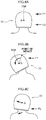
- FIG. 8C When a helmet 10 receives an impact F2 at a position lower than its center of gravity (G) as shown in FIG. 8A to FIG. 8C , the neck of the wearer and the trunk supporting the neck move as shown in FIG. 8C . Because of this, a force that pushes the helmet 10 sideways acts. That is, translational acceleration occurs. However, when the helmet 10 receives an impact F1 at a position higher than its center of gravity (G), a force that tries to rotate the helmet 10 acts as shown in FIG. 8B .
- G center of gravity
- FIG. 1A to FIG. 6 the configuration of the helmet 10 pertaining to an embodiment of the present invention will be described using FIG. 1A to FIG. 6 .
- arrow FR indicates a forward direction in a front and rear direction as seen from the perspective of a wearer currently using the helmet
- arrow RH and arrow LH indicate a rightward direction and a leftward direction, respectively
- arrow UP indicates an upward direction in an up and down direction.
- front/rear, right/left, and upper/lower when the directions of front/rear, right/left, and upper/lower are simply used in the following description, these will be understood to mean front/rear, right/left, and upper/lower as seen from the perspective of the wearer currently wearing the helmet.
- the helmet 10 of the present embodiment has an outer shell 12 formed with a hard material such as fiber-reinforced plastic and a shock absorbing liner 14 disposed inside the shell 12 and joined to an inner surface of the shell 12.
- a hard material such as fiber-reinforced plastic
- a shock absorbing liner 14 disposed inside the shell 12 and joined to an inner surface of the shell 12.
- the shock absorbing liner 14 has a main body liner 16 and an insert liner 18 attached to the main body liner 16. Moreover, the main body liner 16 has a recessed portion 30 for fitting the insert liner 18 therein.
- the main body liner 16 is formed using synthetic resin foam, and the main body liner 16 is formed in the shape of a dome (a recessed shape) in which one side thereof is open.
- the main body liner 16 has a left liner portion 20 and a right liner portion 22 that are disposed along the side portions of the user's head, a rear liner portion 24 that is disposed along the rear portion of the user's head, and a front liner portion 26 that is disposed along the front portion of the user's head.
- the main body liner 16 has an upper liner portion 28 that is disposed opposing the top portion of the user's head.
- the upper liner portion 28 When seen from the underside of the main body liner 16, the upper liner portion 28 has an elliptical shape whose longitudinal direction coincides with the front and rear direction and whose transverse direction coincides with the right and left direction, and the recessed portion 30 into which the insert liner 18 described later (see FIG. 2 ) is fitted is formed in the upper liner portion 28. Ventilation holes 32 that communicate with an air inlet at a front side of the helmet 10 and ventilation holes 32 that communicate with an air outlet at the back side of the helmet 10 are formed in the recessed portion 30. Furthermore, a central recessed portion 36, whose edge portion is circular as seen from below and with which a central raised portion 42 (see FIG.
- the position of the recessed portion 30 in the main body liner 16 is preferably within an elliptical shape formed by the intersection of the surface of the outer shell of the helmet 10 with a cone drawn when the line interconnecting the position of the center of gravity of the helmet 10 and the top of the helmet 10 (see FIG. 8A to FIG. 8C ) is tilted 45 degrees around the helmet 10, and more preferably within a 20-degree cone.
- the original thickness of the main body liner 16 when it is supposed that the recessed portion 30 is not provided is preferably 15 to 55 mm and more preferably 35 to 45 mm.
- the depth of the recessed portion 30 is preferably 35 mm or less and more preferably 25 mm or less.
- the insert liner 18 is formed using synthetic resin foam like the main body liner 16.
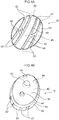
- the insert liner 18 has an insert liner main body portion 40, which is formed in the shape of a shallow bowl (a recessed shape) in which one side thereof is open, and the central raised portion 42 serving as a central support member and the three peripheral raised portions 44 serving as other support members, which project upward from the surface on the upper side of the insert liner main body portion 40.
- the surface on the underside of the insert liner main body portion 40 curves in a shape following the top portion of the user's head, and plural grooves 48 for ventilation are formed therein.
- a thin-walled portion 50 is disposed at the end portion of an outer periphery 49 of the insert liner main body portion 40.
- the thin-walled portion 50 has a thinner wall thickness than the insert liner main body portion 40, and plural cutout portions 52 serving as communicating portions that are continuous with the plural grooves 48 and whose edge portions are substantially U-shaped as seen from below are formed in the thin-wall portion 50.
- the surface on the underside of the insert liner 18 (the surface that contacts the wearer's head) has a shape that is longitudinally and bilaterally symmetrical. To industrially manufacture the insert line 18, it is preferably circular or elliptical in shape.
- the central raised portion 42 is formed substantially in the shape of a solid cylinder and projects upward from the front and rear direction center portion and the right and left direction center portion of the surface on the upper side of the insert liner main body portion 40.
- the three peripheral raised portions 44 are each formed substantially in the shape of a circular truncated cone with a smaller outer diameter than the central raised portion 42.
- two peripheral raised portions 44 disposed an interval apart from each other in the right and left direction are formed at the front side of the central raised portion 42, and one peripheral raised portion 44 is formed in the right and left direction center portion at the rear side of the central raised portion 42.
- the insert liner 18 preferably has a thickness of 5 mm or more from its surface on the underside (the surface facing the wearer's head) to the bottom surface of the recessed portion 30 of the main body liner 16, and more preferably has a thickness of 10 to 15 mm. Moreover, the central raised portion 42 and the peripheral raised portions 44 prevent the insert liner 18 from being pushed by the wearer's head and wobbling when the helmet is put on.
- the peripheral raised portions 44 become deformed, bent, or cracked by the impact force, but because the central raised portion 42 supports the insert liner 18 in its center position, a phenomenon occurs where part of the insert liner 18 sinks into the recessed portion 30 and the part on the opposite side comes up. That is, the insert liner 18 tilts with respect to the main body liner 16.
- the sunk-in peripheral raised portion 44 comes up because of repulsive force from the bottom surface of the recessed portion 30 (the surface of the upper liner portion 28), and then the central raised portion and the other peripheral raised portions 44 to which the impact has propagated after that become deformed, bent, or crack and sink into the recessed portions.
- the insert liner 18 swings (oscillates).
- the peripheral raised portions 44 may also have conical distal ends as shown in FIG. 4C , or may also be shaped like walls (mountain ridgelines) such as the Great Wall of China, for example, as shown in FIG. 4D , so that their area of contact with the bottom surface of the recessed portion 30 becomes smaller.
- the cross section of each of the central raised portion 42 and the peripheral raised portions 44 at the surface on the upper side of the insert liner is preferably circular or elliptical in shape with a diameter of 50 mm or less and more preferably with a diameter or 30 mm or less.
- the insert liner 18 described above is attached (secured) to the main body liner 16 in a state in which the insert liner 18 has been fitted into the recessed portion 30 of the main body liner 16. Specifically, the insert liner 18 is secured to the main body liner 16 in a state in which the central raised portion 42 and the three peripheral raised portions 44 are engaged with the central recessed portion 36 and the three peripheral recessed portions 38 of the main body liner 16. It will be noted that in the present embodiment an adhesive is interposed between the central raised portion 42 of the insert liner 18 and the central recessed portion 36 of the main body liner 16 so that the insert liner 18 does not come away from the main body liner 16 even when the helmet is taken off.
- a gap is formed between the surface on the upper side of the insert liner main body portion 40 of the insert liner 18 and the main body liner 16.
- a gap formed between the outer periphery 49 of the insert liner 18 and the inner wall of the recessed portion 30 is preferably 10 mm or less and more preferably 3 mm to 7 mm.
- the central raised portion 42 and the three peripheral raised portions 44 of the insert liner 18 may be members separate from the insert liner 18 and the main body liner 16, and to industrially manufacture them, the central raised portion 42 and the three peripheral raised portions 44 may be integrally molded on the bottom surface of the insert liner 18 or integrally molded on the bottom surface of the recessed portion 30 of the main body liner 16.
- the thin-walled portion 50 covers and hides the space between the outer periphery 49 of the insert liner 18 and the inner wall of the recessed portion 30; however, when the insert liner 18 swings, the thin-walled portion 50 becomes pushed against the inner wall of the recessed portion 30 and easily becomes deformed or broken, so it does not obstruct the swinging.
- an impact to the outer shell 12 is absorbed as a result of the shock absorbing liner 14 disposed inside the outer shell 12 becoming deformed.
- the insert liner 18 is fitted into the recessed portion 30 of the main body liner 16. Additionally, the central raised portion 42 and the three peripheral raised portions 44 become deformed, thereby reducing translational acceleration, and the insert liner is moved (swings) with respect to the main body liner 16, whereby rotational acceleration of the head of the user wearing the helmet 10 can be effectively reduced.
- a gap is provided between the insert liner 18 and the recessed portion 30, so as soon as the impact travels to the insert liner 18, instantaneously the phenomenon of rising and sinking occurs (i.e., the insert liner 18 swings). Because the insert liner 18 swings in this way, the wearer's head in close contact with the insert liner 18 also swings and rocks together with the insert liner 18. That is, even if the rotation of the helmet 10 is stopped after rotational force has occurred in the helmet 10 because of an impact, the wearer's head inside the helmet 10 continues to move, so the rotational acceleration caused by the impact does not propagate to the inside of the head or can be reduced.
- the insert liner 18 In order to maximize the rocking effect resulting from the rising and sinking (swinging) of the insert liner 18, it is necessary for the insert liner 18 to tilt centering on the center point of the insert liner 18.
- the central raised portion 42 in the center point of the bottom surface of the insert liner 18 and dispose the peripheral raised portions 44 therearound. Furthermore, by giving the peripheral raised portions 44 a shape that becomes deformed more easily than the central raised portion 42, deformation occurs starting at the peripheral raised portions 44 because of an impact, so the tilting of the insert liner 18 centered on the central raised portion 42 can be promoted.
- the helmet 10 was put on a model head and dropped on top of a steel anvil from a height of 2.5 m, and the rotational force produced by the impact at that time was measured by an angular velocimeter. It will be noted that the places of impact were the three points of the vicinity of the top portion of the helmet 10, the front portion in a case where the helmet 10 was tilted 45 degrees forward, and the left side portion in a case where the helmet was tilted 45 degrees leftward.
- Table 1 Impact Test Results (Unit: rad/s2) When Conventional Insert Liner was Used When Swinging Insert Liner was Used Top Portion 10,133 6,665 Front Portion 12,280 10,692 Left Side Portion 10,571 8,731
- the insert liner 18 can be maintained in a stable state by providing the three peripheral raised portions 44 in addition to the central raised portion 42.
- the insert liner 18 is unstable just with the wearer putting on the helmet 10 (the insert liner 18 easily tilt's with respect to the main body liner 16), so comfort is poor. Furthermore, if the translational acceleration of the impact is too large, it is expected that the central raised portion 42 will not be able to support the wearer's head and be easily crushed, resulting in the insert liner 18 caving in substantially parallel to the recessed portion 30. That is, in this case, the rising and sinking phenomenon of the insert liner 18 does not occur.
- the force with which the insert liner 18 is supported can be reinforced.
- translational acceleration can be buffered as a result of any of the three peripheral raised portions 44 being deformed or bent, and rotational acceleration can also be buffered as a result of the insert liner 18 producing the rising and sinking phenomenon.
- the ventilation holes 32, 34 serving as ventilation passages that communicate with the air inlet at the front side of the helmet 10 and the air outlet at the back side of the helmet 10 are provided, and the cutout portions 52 that communicate the recessed portion 30 with the wearer's head region are provided at the insert liner 18.
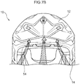
- An air flow arises wherein outside air taken in through the air inlet in the front face of the helmet 10 is introduced through the ventilation holes 32 formed in the recessed portion 30 of the main body liner 16 to the inside of the recessed portion 30 and is then discharged via the ventilation holes 34 through the air outlet.
- the ventilation performance inside the helmet 10 can be enhanced. That is, heat inside the helmet 10 is discharged so that comfort can be provided to the wearer. Furthermore, by providing, in the top portion including the recessed portion 30, the ventilation holes 32, 34 that communicate with the front side and back side of the helmet 10, the main body liner 16 more easily absorbs translational acceleration caused by an impact. It will be noted that although in the present embodiment the cutout portions 52 are provided as the communicating portions for communicating the wearer's head region with the recessed portion 30, the communicating portions are not limited to this, and plural communicating holes that run through the insert liner 18 may also be provided.
- the thin-walled portion 50 whose thickness is thinner compared to the thickness of a center portion 46 is disposed at the end portion of the outer periphery 49 of the insert liner main body portion 40.
- the plural cutout portions 52 are formed in the thin-walled portion 50. The rigidity of the thin-walled portion 50 is reduced because of the cutout portions 52. Because of this, when the helmet 10 is impacted, the thin-walled portion 50 is easily deformed or broken, so the thin-walled portion 50 does not obstruct the moving (swinging) of the insert liner.
- the insert liner 18 is reinforced by disposing the plural peripheral raised portions 44 around the central raised portion 42 so that the central raised portion 42 does not become crushed and the insert liner 18 swings without collapsing into the recessed portion 30.
- the air inlet is provided at an edge-rolled member 54 in the open portion of the front face of the helmet, and outside air that has been taken in is divided in two, with one flow traveling over the outer surface of the main body liner 16 and reaching the recessed portion 30 through the ventilation holes 32 and the other flow traveling over the inner surface of the main body liner 16 and being guided to the ventilation grooves 48 provided at the underside of the insert liner 18.
- the number of parts for the air inlet can be reduced and the number of manhours for assembly can be reduced.
Landscapes
- Helmets And Other Head Coverings (AREA)
Applications Claiming Priority (2)
| Application Number | Priority Date | Filing Date | Title |
|---|---|---|---|
| JP2017100732A JP6842991B2 (ja) | 2017-05-22 | 2017-05-22 | ヘルメット |
| PCT/JP2018/008423 WO2018216306A1 (ja) | 2017-05-22 | 2018-03-05 | ヘルメット |
Publications (3)
| Publication Number | Publication Date |
|---|---|
| EP3636092A1 true EP3636092A1 (de) | 2020-04-15 |
| EP3636092A4 EP3636092A4 (de) | 2021-03-17 |
| EP3636092B1 EP3636092B1 (de) | 2025-09-03 |
Family
ID=64395422
Family Applications (1)
| Application Number | Title | Priority Date | Filing Date |
|---|---|---|---|
| EP18806345.7A Active EP3636092B1 (de) | 2017-05-22 | 2018-03-05 | Helm |
Country Status (5)
| Country | Link |
|---|---|
| US (1) | US11253021B2 (de) |
| EP (1) | EP3636092B1 (de) |
| JP (1) | JP6842991B2 (de) |
| CN (1) | CN110785096B (de) |
| WO (1) | WO2018216306A1 (de) |
Families Citing this family (18)
| Publication number | Priority date | Publication date | Assignee | Title |
|---|---|---|---|---|
| US11730222B2 (en) | 2014-02-21 | 2023-08-22 | Matscitechno Licensing Company | Helmet padding system |
| US11744312B2 (en) | 2014-02-21 | 2023-09-05 | Matscitechno Licensing Company | Helmet padding system |
| US11659882B2 (en) | 2014-02-21 | 2023-05-30 | Matscitechno Licensing Company | Helmet padding system |
| US20180235303A1 (en) * | 2014-02-21 | 2018-08-23 | Matscitechno Licensing Company | Helmet padding system |
| USD967543S1 (en) * | 2018-01-25 | 2022-10-18 | Bell Sports, Inc. | Helmet with integrated shoulder pad |
| USD908971S1 (en) * | 2018-07-20 | 2021-01-26 | Hjc Corp. | Helmet |
| USD949483S1 (en) * | 2019-08-05 | 2022-04-19 | H&H Sports Protection S.R.L. | Protective helmet |
| IT201900020410A1 (it) * | 2019-11-05 | 2021-05-05 | Kask Spa | Casco |
| US11540578B2 (en) | 2020-03-12 | 2023-01-03 | Matscitechno Licensing Company | Helmet system |
| US11540577B2 (en) | 2020-03-12 | 2023-01-03 | Matscitechno Licensing Company | Helmet system |
| USD977198S1 (en) * | 2020-06-23 | 2023-01-31 | Bell Sports, Inc. | Helmet |
| WO2022168366A1 (ja) | 2021-02-05 | 2022-08-11 | 株式会社Shoei | ヘルメットおよびヘルメットの製造方法 |
| USD974704S1 (en) * | 2021-03-10 | 2023-01-10 | H&H Sports Protection S.R.L. | Helmet |
| USD1102040S1 (en) * | 2023-02-27 | 2025-11-11 | Fox Head, Inc. | Helmet |
| USD1115181S1 (en) * | 2023-05-10 | 2026-02-24 | Bell Sports, Inc. | Helmet with cheek pads |
| USD1094899S1 (en) | 2023-08-22 | 2025-09-23 | Liding Tang | Motorcycle helmet |
| USD1111320S1 (en) * | 2024-07-24 | 2026-02-10 | Henry Tedjakusuma | Helmet |
| CN223111130U (zh) * | 2024-10-22 | 2025-07-18 | 绍兴锐风运动用品有限公司 | 一种带鼻梁保护的头盔 |
Family Cites Families (18)
| Publication number | Priority date | Publication date | Assignee | Title |
|---|---|---|---|---|
| WO1991005489A1 (en) * | 1989-10-16 | 1991-05-02 | Rosebank Plastics Pty. Ltd. | Safety helmet and liner therefor |
| AU661758B2 (en) * | 1992-05-20 | 1995-08-03 | Shoei Kako Kabushiki Kaisha | Vehicle helmet |
| JP3825106B2 (ja) * | 1995-10-30 | 2006-09-20 | 株式会社Shoei | 安全用ヘルメットのための頭部保護体 |
| DE69614965T2 (de) | 1995-10-30 | 2002-04-25 | Shoei Kako Co., Ltd. | Sicherheitshelm und Kopfschützvorrichtung dafür |
| JP3765377B2 (ja) | 2000-04-04 | 2006-04-12 | 本田技研工業株式会社 | ヘルメット |
| DE20007004U1 (de) * | 2000-04-15 | 2000-07-27 | Beck, Hans, 69412 Eberbach | Sturzhelm mit einer sich der Kopfform anpassenden Einlage |
| US20020174480A1 (en) * | 2001-05-25 | 2002-11-28 | Lombard Shoghi A. | Sports helmet and face guard |
| US7802320B2 (en) * | 2005-06-30 | 2010-09-28 | Morgan Don E | Helmet padding |
| KR101003670B1 (ko) * | 2009-01-09 | 2010-12-23 | 고환복 | 헬멧 |
| PT2428129E (pt) * | 2010-09-09 | 2013-06-24 | Oliver Schimpf | Capacete de protecção |
| CN103635112B (zh) * | 2011-02-09 | 2015-12-23 | 6D头盔有限责任公司 | 头盔全向能量管理系统 |
| US20140259316A1 (en) * | 2013-03-15 | 2014-09-18 | Barry H. Katz | Helmet system |
| JP6163366B2 (ja) * | 2013-06-27 | 2017-07-12 | 株式会社Shoei | ヘルメット |
| US10736373B2 (en) * | 2013-08-13 | 2020-08-11 | Smith Optics, Inc. | Helmet with shock absorbing inserts |
| JP2016539253A (ja) * | 2013-12-06 | 2016-12-15 | ベル スポーツ, インコーポレイテッド | 可撓性多層ヘルメット及びその作製方法 |
| EP3117726B1 (de) * | 2015-07-17 | 2018-07-18 | Anomaly Action Sports S.r.l. | Schutzhelm |
| CN204742762U (zh) * | 2015-07-22 | 2015-11-11 | 宁波西博恩新材料科技有限公司 | 一种安全防护专用头盔 |
| EP3397101A4 (de) * | 2016-01-04 | 2019-08-28 | Bell Sports, Inc. | Helm mit grenznoppe und elastomerhalterungen |
-
2017
- 2017-05-22 JP JP2017100732A patent/JP6842991B2/ja active Active
-
2018
- 2018-03-05 WO PCT/JP2018/008423 patent/WO2018216306A1/ja not_active Ceased
- 2018-03-05 EP EP18806345.7A patent/EP3636092B1/de active Active
- 2018-03-05 CN CN201880033641.3A patent/CN110785096B/zh active Active
- 2018-03-05 US US16/615,651 patent/US11253021B2/en active Active
Also Published As
| Publication number | Publication date |
|---|---|
| US11253021B2 (en) | 2022-02-22 |
| US20200085131A1 (en) | 2020-03-19 |
| JP6842991B2 (ja) | 2021-03-17 |
| JP2018193654A (ja) | 2018-12-06 |
| EP3636092A4 (de) | 2021-03-17 |
| CN110785096B (zh) | 2022-06-14 |
| CN110785096A (zh) | 2020-02-11 |
| WO2018216306A1 (ja) | 2018-11-29 |
| EP3636092B1 (de) | 2025-09-03 |
Similar Documents
| Publication | Publication Date | Title |
|---|---|---|
| EP3636092B1 (de) | Helm | |
| US11864615B2 (en) | Helmet with shock absorbing inserts | |
| JP4059729B2 (ja) | 安全用ヘルメットのための頭部保護体 | |
| US4564959A (en) | Crash helmet | |
| US4447914A (en) | Goggle | |
| KR102207958B1 (ko) | 헬멧 | |
| JP2002531719A (ja) | 保護ヘルメット | |
| US20180132557A1 (en) | Improvements to Skull Protection Cell | |
| EP1839510A1 (de) | Befestigungsvorrichtung für einen Helmgurt | |
| JP5591984B1 (ja) | ヘルメット | |
| JP3131987U (ja) | 衝撃吸収帽子 | |
| US7421744B1 (en) | Motorcycle helmet with integrated acoustic voice amplified chambers | |
| US20240090612A1 (en) | Helmet and method for manufacturing helmet | |
| JP4233030B2 (ja) | ヘルメットのベンチレーション構造 | |
| JP3825106B2 (ja) | 安全用ヘルメットのための頭部保護体 | |
| JP2021147731A (ja) | ヘルメット | |
| JP6247143B2 (ja) | ヘルメット | |
| JP2021147732A (ja) | ヘルメット | |
| JP2007260316A (ja) | アイアンゴルフクラブ | |
| US20180242675A1 (en) | Helmet | |
| RU2184471C1 (ru) | Защитная каска | |
| JP3888186B2 (ja) | ドアトリムの衝撃吸収構造 | |
| JP6385877B2 (ja) | ヘルメット | |
| JP2018024974A (ja) | ヘルメット | |
| JPH09188912A (ja) | 安全用ヘルメットのための頭部保護体 |
Legal Events
| Date | Code | Title | Description |
|---|---|---|---|
| STAA | Information on the status of an ep patent application or granted ep patent |
Free format text: STATUS: THE INTERNATIONAL PUBLICATION HAS BEEN MADE |
|
| PUAI | Public reference made under article 153(3) epc to a published international application that has entered the european phase |
Free format text: ORIGINAL CODE: 0009012 |
|
| STAA | Information on the status of an ep patent application or granted ep patent |
Free format text: STATUS: REQUEST FOR EXAMINATION WAS MADE |
|
| 17P | Request for examination filed |
Effective date: 20191204 |
|
| AK | Designated contracting states |
Kind code of ref document: A1 Designated state(s): AL AT BE BG CH CY CZ DE DK EE ES FI FR GB GR HR HU IE IS IT LI LT LU LV MC MK MT NL NO PL PT RO RS SE SI SK SM TR |
|
| AX | Request for extension of the european patent |
Extension state: BA ME |
|
| DAV | Request for validation of the european patent (deleted) | ||
| DAX | Request for extension of the european patent (deleted) | ||
| A4 | Supplementary search report drawn up and despatched |
Effective date: 20210212 |
|
| RIC1 | Information provided on ipc code assigned before grant |
Ipc: A42B 3/12 20060101AFI20210208BHEP Ipc: A42B 3/06 20060101ALI20210208BHEP Ipc: A42B 3/28 20060101ALI20210208BHEP |
|
| STAA | Information on the status of an ep patent application or granted ep patent |
Free format text: STATUS: EXAMINATION IS IN PROGRESS |
|
| 17Q | First examination report despatched |
Effective date: 20221019 |
|
| GRAP | Despatch of communication of intention to grant a patent |
Free format text: ORIGINAL CODE: EPIDOSNIGR1 |
|
| STAA | Information on the status of an ep patent application or granted ep patent |
Free format text: STATUS: GRANT OF PATENT IS INTENDED |
|
| INTG | Intention to grant announced |
Effective date: 20250530 |
|
| GRAS | Grant fee paid |
Free format text: ORIGINAL CODE: EPIDOSNIGR3 |
|
| GRAA | (expected) grant |
Free format text: ORIGINAL CODE: 0009210 |
|
| STAA | Information on the status of an ep patent application or granted ep patent |
Free format text: STATUS: THE PATENT HAS BEEN GRANTED |
|
| AK | Designated contracting states |
Kind code of ref document: B1 Designated state(s): AL AT BE BG CH CY CZ DE DK EE ES FI FR GB GR HR HU IE IS IT LI LT LU LV MC MK MT NL NO PL PT RO RS SE SI SK SM TR |
|
| REG | Reference to a national code |
Ref country code: GB Ref legal event code: FG4D |
|
| REG | Reference to a national code |
Ref country code: CH Ref legal event code: EP |
|
| REG | Reference to a national code |
Ref country code: DE Ref legal event code: R096 Ref document number: 602018085244 Country of ref document: DE |
|
| P01 | Opt-out of the competence of the unified patent court (upc) registered |
Free format text: CASE NUMBER: UPC_APP_3953_3636092/2025 Effective date: 20250821 |
|
| REG | Reference to a national code |
Ref country code: IE Ref legal event code: FG4D |
|
| REG | Reference to a national code |
Ref country code: NL Ref legal event code: MP Effective date: 20250903 |
|
| PG25 | Lapsed in a contracting state [announced via postgrant information from national office to epo] |
Ref country code: NO Free format text: LAPSE BECAUSE OF FAILURE TO SUBMIT A TRANSLATION OF THE DESCRIPTION OR TO PAY THE FEE WITHIN THE PRESCRIBED TIME-LIMIT Effective date: 20251203 |
|
| REG | Reference to a national code |
Ref country code: LT Ref legal event code: MG9D |
|
| PG25 | Lapsed in a contracting state [announced via postgrant information from national office to epo] |
Ref country code: FI Free format text: LAPSE BECAUSE OF FAILURE TO SUBMIT A TRANSLATION OF THE DESCRIPTION OR TO PAY THE FEE WITHIN THE PRESCRIBED TIME-LIMIT Effective date: 20250903 |
|
| PG25 | Lapsed in a contracting state [announced via postgrant information from national office to epo] |
Ref country code: HR Free format text: LAPSE BECAUSE OF FAILURE TO SUBMIT A TRANSLATION OF THE DESCRIPTION OR TO PAY THE FEE WITHIN THE PRESCRIBED TIME-LIMIT Effective date: 20250903 |
|
| PG25 | Lapsed in a contracting state [announced via postgrant information from national office to epo] |
Ref country code: GR Free format text: LAPSE BECAUSE OF FAILURE TO SUBMIT A TRANSLATION OF THE DESCRIPTION OR TO PAY THE FEE WITHIN THE PRESCRIBED TIME-LIMIT Effective date: 20251204 |
|
| PG25 | Lapsed in a contracting state [announced via postgrant information from national office to epo] |
Ref country code: SE Free format text: LAPSE BECAUSE OF FAILURE TO SUBMIT A TRANSLATION OF THE DESCRIPTION OR TO PAY THE FEE WITHIN THE PRESCRIBED TIME-LIMIT Effective date: 20250903 |
|
| PG25 | Lapsed in a contracting state [announced via postgrant information from national office to epo] |
Ref country code: LV Free format text: LAPSE BECAUSE OF FAILURE TO SUBMIT A TRANSLATION OF THE DESCRIPTION OR TO PAY THE FEE WITHIN THE PRESCRIBED TIME-LIMIT Effective date: 20250903 |
|
| PG25 | Lapsed in a contracting state [announced via postgrant information from national office to epo] |
Ref country code: BG Free format text: LAPSE BECAUSE OF FAILURE TO SUBMIT A TRANSLATION OF THE DESCRIPTION OR TO PAY THE FEE WITHIN THE PRESCRIBED TIME-LIMIT Effective date: 20250903 Ref country code: PL Free format text: LAPSE BECAUSE OF FAILURE TO SUBMIT A TRANSLATION OF THE DESCRIPTION OR TO PAY THE FEE WITHIN THE PRESCRIBED TIME-LIMIT Effective date: 20250903 |
|
| PG25 | Lapsed in a contracting state [announced via postgrant information from national office to epo] |
Ref country code: RS Free format text: LAPSE BECAUSE OF FAILURE TO SUBMIT A TRANSLATION OF THE DESCRIPTION OR TO PAY THE FEE WITHIN THE PRESCRIBED TIME-LIMIT Effective date: 20251203 |
|
| PG25 | Lapsed in a contracting state [announced via postgrant information from national office to epo] |
Ref country code: ES Free format text: LAPSE BECAUSE OF FAILURE TO SUBMIT A TRANSLATION OF THE DESCRIPTION OR TO PAY THE FEE WITHIN THE PRESCRIBED TIME-LIMIT Effective date: 20250903 |
|
| REG | Reference to a national code |
Ref country code: AT Ref legal event code: MK05 Ref document number: 1831871 Country of ref document: AT Kind code of ref document: T Effective date: 20250903 |
|
| PG25 | Lapsed in a contracting state [announced via postgrant information from national office to epo] |
Ref country code: NL Free format text: LAPSE BECAUSE OF FAILURE TO SUBMIT A TRANSLATION OF THE DESCRIPTION OR TO PAY THE FEE WITHIN THE PRESCRIBED TIME-LIMIT Effective date: 20250903 |
|
| PG25 | Lapsed in a contracting state [announced via postgrant information from national office to epo] |
Ref country code: SM Free format text: LAPSE BECAUSE OF FAILURE TO SUBMIT A TRANSLATION OF THE DESCRIPTION OR TO PAY THE FEE WITHIN THE PRESCRIBED TIME-LIMIT Effective date: 20250903 |
|
| PGFP | Annual fee paid to national office [announced via postgrant information from national office to epo] |
Ref country code: GB Payment date: 20260324 Year of fee payment: 9 |
|
| PGFP | Annual fee paid to national office [announced via postgrant information from national office to epo] |
Ref country code: DE Payment date: 20260319 Year of fee payment: 9 |
|
| PG25 | Lapsed in a contracting state [announced via postgrant information from national office to epo] |
Ref country code: AT Free format text: LAPSE BECAUSE OF FAILURE TO SUBMIT A TRANSLATION OF THE DESCRIPTION OR TO PAY THE FEE WITHIN THE PRESCRIBED TIME-LIMIT Effective date: 20250903 |
|
| PGFP | Annual fee paid to national office [announced via postgrant information from national office to epo] |
Ref country code: IT Payment date: 20260324 Year of fee payment: 9 |
|
| PG25 | Lapsed in a contracting state [announced via postgrant information from national office to epo] |
Ref country code: IS Free format text: LAPSE BECAUSE OF FAILURE TO SUBMIT A TRANSLATION OF THE DESCRIPTION OR TO PAY THE FEE WITHIN THE PRESCRIBED TIME-LIMIT Effective date: 20260103 |
|
| PGFP | Annual fee paid to national office [announced via postgrant information from national office to epo] |
Ref country code: FR Payment date: 20260320 Year of fee payment: 9 |
|
| PG25 | Lapsed in a contracting state [announced via postgrant information from national office to epo] |
Ref country code: CZ Free format text: LAPSE BECAUSE OF FAILURE TO SUBMIT A TRANSLATION OF THE DESCRIPTION OR TO PAY THE FEE WITHIN THE PRESCRIBED TIME-LIMIT Effective date: 20250903 Ref country code: PT Free format text: LAPSE BECAUSE OF FAILURE TO SUBMIT A TRANSLATION OF THE DESCRIPTION OR TO PAY THE FEE WITHIN THE PRESCRIBED TIME-LIMIT Effective date: 20260105 |
|
| PG25 | Lapsed in a contracting state [announced via postgrant information from national office to epo] |
Ref country code: EE Free format text: LAPSE BECAUSE OF FAILURE TO SUBMIT A TRANSLATION OF THE DESCRIPTION OR TO PAY THE FEE WITHIN THE PRESCRIBED TIME-LIMIT Effective date: 20250903 Ref country code: SK Free format text: LAPSE BECAUSE OF FAILURE TO SUBMIT A TRANSLATION OF THE DESCRIPTION OR TO PAY THE FEE WITHIN THE PRESCRIBED TIME-LIMIT Effective date: 20250903 |