EP3636100B1 - Behälter für pulverförmiges kosmetikprodukt, der eine verbesserte öffnungs-/schliessvorrichtung umfasst - Google Patents
Behälter für pulverförmiges kosmetikprodukt, der eine verbesserte öffnungs-/schliessvorrichtung umfasst Download PDFInfo
- Publication number
- EP3636100B1 EP3636100B1 EP19201239.1A EP19201239A EP3636100B1 EP 3636100 B1 EP3636100 B1 EP 3636100B1 EP 19201239 A EP19201239 A EP 19201239A EP 3636100 B1 EP3636100 B1 EP 3636100B1
- Authority
- EP
- European Patent Office
- Prior art keywords
- orifices
- membrane
- housing
- flexible membrane
- base
- Prior art date
- Legal status (The legal status is an assumption and is not a legal conclusion. Google has not performed a legal analysis and makes no representation as to the accuracy of the status listed.)
- Active
Links
Images





Classifications
-
- B—PERFORMING OPERATIONS; TRANSPORTING
- B65—CONVEYING; PACKING; STORING; HANDLING THIN OR FILAMENTARY MATERIAL
- B65D—CONTAINERS FOR STORAGE OR TRANSPORT OF ARTICLES OR MATERIALS, e.g. BAGS, BARRELS, BOTTLES, BOXES, CANS, CARTONS, CRATES, DRUMS, JARS, TANKS, HOPPERS, FORWARDING CONTAINERS; ACCESSORIES, CLOSURES, OR FITTINGS THEREFOR; PACKAGING ELEMENTS; PACKAGES
- B65D47/00—Closures with filling and discharging, or with discharging, devices
- B65D47/04—Closures with discharging devices other than pumps
- B65D47/06—Closures with discharging devices other than pumps with pouring spouts or tubes; with discharge nozzles or passages
-
- A—HUMAN NECESSITIES
- A45—HAND OR TRAVELLING ARTICLES
- A45D—HAIRDRESSING OR SHAVING EQUIPMENT; EQUIPMENT FOR COSMETICS OR COSMETIC TREATMENTS, e.g. FOR MANICURING OR PEDICURING
- A45D33/00—Containers or accessories specially adapted for handling powdery toiletry or cosmetic substances
- A45D33/02—Containers or accessories specially adapted for handling powdery toiletry or cosmetic substances with dispensing means, e.g. sprinkling means
-
- A—HUMAN NECESSITIES
- A45—HAND OR TRAVELLING ARTICLES
- A45D—HAIRDRESSING OR SHAVING EQUIPMENT; EQUIPMENT FOR COSMETICS OR COSMETIC TREATMENTS, e.g. FOR MANICURING OR PEDICURING
- A45D33/00—Containers or accessories specially adapted for handling powdery toiletry or cosmetic substances
- A45D33/003—Powder boxes
-
- A—HUMAN NECESSITIES
- A45—HAND OR TRAVELLING ARTICLES
- A45D—HAIRDRESSING OR SHAVING EQUIPMENT; EQUIPMENT FOR COSMETICS OR COSMETIC TREATMENTS, e.g. FOR MANICURING OR PEDICURING
- A45D33/00—Containers or accessories specially adapted for handling powdery toiletry or cosmetic substances
- A45D33/02—Containers or accessories specially adapted for handling powdery toiletry or cosmetic substances with dispensing means, e.g. sprinkling means
- A45D33/025—Containers or accessories specially adapted for handling powdery toiletry or cosmetic substances with dispensing means, e.g. sprinkling means for compacts, vanity boxes or cases
-
- A—HUMAN NECESSITIES
- A45—HAND OR TRAVELLING ARTICLES
- A45D—HAIRDRESSING OR SHAVING EQUIPMENT; EQUIPMENT FOR COSMETICS OR COSMETIC TREATMENTS, e.g. FOR MANICURING OR PEDICURING
- A45D33/00—Containers or accessories specially adapted for handling powdery toiletry or cosmetic substances
- A45D33/02—Containers or accessories specially adapted for handling powdery toiletry or cosmetic substances with dispensing means, e.g. sprinkling means
- A45D33/06—Containers or accessories specially adapted for handling powdery toiletry or cosmetic substances with dispensing means, e.g. sprinkling means with diaphragm bases
-
- A—HUMAN NECESSITIES
- A45—HAND OR TRAVELLING ARTICLES
- A45D—HAIRDRESSING OR SHAVING EQUIPMENT; EQUIPMENT FOR COSMETICS OR COSMETIC TREATMENTS, e.g. FOR MANICURING OR PEDICURING
- A45D33/00—Containers or accessories specially adapted for handling powdery toiletry or cosmetic substances
- A45D33/02—Containers or accessories specially adapted for handling powdery toiletry or cosmetic substances with dispensing means, e.g. sprinkling means
- A45D33/16—Containers or accessories specially adapted for handling powdery toiletry or cosmetic substances with dispensing means, e.g. sprinkling means with openings in the lid, able to be opened or closed by displacing or rotating a covering part
-
- B—PERFORMING OPERATIONS; TRANSPORTING
- B65—CONVEYING; PACKING; STORING; HANDLING THIN OR FILAMENTARY MATERIAL
- B65D—CONTAINERS FOR STORAGE OR TRANSPORT OF ARTICLES OR MATERIALS, e.g. BAGS, BARRELS, BOTTLES, BOXES, CANS, CARTONS, CRATES, DRUMS, JARS, TANKS, HOPPERS, FORWARDING CONTAINERS; ACCESSORIES, CLOSURES, OR FITTINGS THEREFOR; PACKAGING ELEMENTS; PACKAGES
- B65D41/00—Caps, e.g. crown caps or crown seals, i.e. members having parts arranged for engagement with the external periphery of a neck or wall defining a pouring opening or discharge aperture; Protective cap-like covers for closure members, e.g. decorative covers of metal foil or paper
- B65D41/62—Secondary protective cap-like outer covers for closure members
Definitions
- the invention relates to a casing for a powder cosmetic product comprising an improved opening-closing device.
- the invention relates more particularly to a casing for a powder cosmetic product, comprising at least a cover and a base which are mounted movably relative to each other between at least a closed position and an open position of the casing, in which the base comprises a cavity intended to receive said pulverulent cosmetic product which is closed by an opening-closing device, said opening-closing device comprising at least first means which, comprising first orifices in communication with the cavity, are integral of the base, and of the second means which, comprising second orifices, are mounted to be movable in rotation with respect to the first means between at least one closed position and one position of use.
- the housing comprises a base comprising a cavity intended to contain a powder cosmetic product, a sieve which is arranged at the level of the opening of the cavity and through the orifices of which the cosmetic product is discharged with a view to its. use.
- the screen is rigid.
- the screen is for example produced in the form of a perforated plate provided with orifices, such as a network of circular holes.
- Such a housing has the particular drawback of exhibiting a dispersion of the pulverulent cosmetic product through the multiple orifices of the sieve, in other words an uncontrolled unloading of said product from the cavity forming the reservoir.
- Dispersion of the cosmetic product through the sieve is liable to occur, on the one hand, during transport of the housing (in the closed position) and, on the other hand, during use of the housing (in the open position).
- the dispersion of the cosmetic product is limited by a cover which in the closed position covers the sieve.
- the dispersion of the powder cosmetic product is further inevitable since it is necessary to shake or invert the casing in order to obtain delivery of the cosmetic product.
- Such gestures are even more important when, during use, the amount of cosmetic product present in the cavity decreases.
- the sieve used is “flexible” in order in particular to allow access to the cosmetic product located in the cavity and, by comparison with a rigid sieve housing, without necessarily having to. shake the housing.
- the flexible sieve is for example produced in the form of a grid, made of nylon or other material, consisting of a set of meshes each delimiting one of the orifices for passage of the pulverulent cosmetic product out of the cavity.
- such a housing has the particular drawback of having a dispersion of the pulverulent cosmetic product through the multiple orifices of the sieve, on the one hand during transport of the housing (in the closed position) and, on the other hand, during use of the housing (in the open position).
- an applicator - typically a sponge - so that at least part of the cosmetic product dispersed through the orifices is captured by the sponge.
- the sponge does not completely prevent the dispersion of the pulverulent cosmetic product out of the cavity, which poses a problem of hygiene (or cleanliness) of the housing.
- the sponge then comprises on its face in contact with the grid an often excessive quantity of cosmetic product so that the saturated sponge is then difficult to use for applying make-up.
- a stopper for example integral with the cover of the housing.
- Such a stopper is configured to cover the sieve in the closed position of the housing so as to isolate it and thus prevent the pulverulent cosmetic product from being able to disperse.
- the cosmetic product present on the surface of the stopper is then liable to disperse everywhere after opening the cover, in particular from dirtying the housing, the user's hands, etc.
- Such a design also has the drawback of adding, with said stopper, an additional part to the cover, or even an additional part to the casing, which in particular has the consequence of increasing the manufacturing cost thereof.
- the cap does not completely solve the problem of dispersion because the problem of dispersion or uncontrolled unloading is not limited to the only case of transporting the housing but also occurs during use, when the housing is in the open position. .
- the sieve is generally sized to have a reduced surface area, in particular a surface smaller than the diameter of the housing, which furthermore has the consequence of limiting the gestures of the user handling an applicator during the application. use of the housing.
- the reduction of the surface of the flexible sieve makes it possible to reduce the phenomenon of dispersion of the cosmetic product, the volatility of which would otherwise be too great.
- the pulverulent cosmetic product will disperse, spread, when the applicator comes into contact with the sieve, or even when the base of the housing is shaken to discharge the product onto an applicator such as a sponge.
- the housing comprises an opening-closing device of the rotary type comprising a first screen and a second screen which are superimposed and one of which is mounted to be movable in rotation with respect to the other, respectively between a shutter position and a position of use.
- the closed position of the opening-closing device corresponds to a position in which the orifices of the second sieve are angularly offset with respect to the orifices of the first sieve arranged below so as to block the passage of the pulverulent cosmetic product contained in a cavity of the base of the housing which the said opening-closing device closes.
- the position of use of the opening-closing device corresponds to a position in which the orifices of the second sieve are superimposed with the orifices of the first sieve so as to allow the passage of the pulverulent cosmetic product successively through the orifices of the first sieve and the orifices of the second screen.
- the orifices passing through the screens are for example formed by a network of holes or perforations.
- An opening-closing device of this type makes it possible to eliminate the use of a stopper described above for a housing comprising a single sieve.
- the opening-closing device of such a housing having been previously actuated to occupy said position of use, the distribution of the cosmetic product through said orifices of the two superimposed sieves is obtained by overturning the housing, or even by stirring. or by shaking the base of the case.
- the gestures associated with the delivery of the cosmetic product from such a case during its use greatly generate a dispersion of the cosmetic product.
- the powdered cosmetic product delivered disperses without control when it leaves the orifices of the sieves, for example to be collected by means of an applicator or sometimes in the cover.
- the quantity delivered by the opening-closing device is predetermined by the configuration of two screens, more particularly the number of orifices, the dimensions of the orifices, etc. so that the amount of powder cosmetic product is delivered without control or great precision.
- the dispersion of the cosmetic product occurring during use directly affects the general hygiene of the housing, including subsequently during transport and despite the opening-closing device.
- the powdered cosmetic product thus dispersed is capable of escaping outside the housing even when the latter is closed by a cover.
- An aim of the present invention is to provide a new design of an opening-closing device for a casing for a powder cosmetic product in order in particular to resolve at least part of the drawbacks of the state of the product.
- technique in particular the problems of dispersion and hygiene, while also proposing a housing offering simple and pleasant user gestures, allowing the user to freely choose the amount of powdered cosmetic product.
- the invention according to claim 1 provides a housing of the type described above, characterized in that the first means comprise at least one first flexible membrane and the second means comprise at least one second flexible membrane.
- the two flexible or flexible membranes of the opening-closing device are configured to limit the dispersion of the pulverulent cosmetic product, in particular by virtue of the orifices that each of said membranes comprise.
- the orifices of each flexible membrane generally have the shape of a non-rectilinear slot extending radially between the center of the membrane and its outer periphery, preferably widening from the center outwards.
- the flexible membranes are made of an elastomeric material, preferably of silicone.
- the flexible membranes according to the invention are generally more rigid.
- the flexible membranes are locally more flexible thanks to the presence of the orifices, in particular thanks to their shapes such as slits, but also thanks to the choice of the material, the thickness of each flexible membrane so that the flexibility of 'a membrane is determined by the combination of these different elements.
- the flexible membranes make it possible, during use, to access the pulverulent cosmetic product contained in the cavity, in particular to find said product more easily at the bottom as well as at the periphery in the zone of the cavity radially remote from the center of the cavity. the base.
- the orifices of the flexible membranes participate in increasing the elasticity of the membranes, in increasing their capacity for elastic deformation in use, in particular under the action of an applicator.
- said orifices formed by non-rectilinear radial slots, in particular curved or curved make it possible, by perforating each of the membranes, to obtain an additional deformation capacity, without however having to reduce the thickness of the flexible membranes at the risk of weakening them.
- slits having a curved or curved shape make it possible to obtain an increased deformation of the membrane at the level of the bearing zone of the applicator.
- the axis of deformation or of folding of a flexible membrane comprising slots having such non-rectilinear shapes is an axis which extends radially from one end to the other of the slot and is located outside the slit, in the membrane material between consecutive slits.
- the deformation obtained would be less with a membrane comprising rectilinear slots for which said deformation axis extending radially from one end to the other of the slot coincides with one of the edges of the slot and this which then limits the possibility of access to the bottom of the cavity or its periphery.
- the pressure exerted locally by an applicator on the flexible membranes causes a deformation of the non-rectilinear slits located in the contact zone and is advantageously accompanied by a phenomenon of “closing” of the slits located radially opposite the contact zone.
- the slits will stretch radially due to the deformation of each of the flexible membranes and thereby shrink, their radial edges approaching, which then makes it possible to limit the dispersion of the powder cosmetic product in the areas which are not. not in contact with the applicator.
- the opening-closing device of the case according to the invention makes it possible at the very least to limit, thanks to the membranes, the dispersion of the pulverulent cosmetic product, and this both during transport and during use of the case.
- the pulverulent cosmetic product is held inside the cavity, the opening of which is closed by the two membranes of the opening-closing device occupying said closed position.
- the sealing means arranged between the two membranes, the contact between the respectively upper and lower faces of the two membranes in the closed position further complete the sealing obtained with the membranes and thereby hygiene (or cleanliness). ) of the housing thanks to the limitation of dispersion.
- the sealing means cooperating with the cover in the closed position participate in improving the hygiene (or cleanliness) of the housing, by preventing the cosmetic product from being dispersed after use, in particular during transport.
- the flexible membranes of the opening-closing device occupying the position of use, the powder cosmetic product is accessible through the respective openings of the membranes.
- the dispersion of the cosmetic product is therefore not possible when the membranes form a barrier between two consecutive orifices.
- the dispersion is thus limited by the solid parts of the membranes, improving the hygiene (or cleanliness) of the housing.
- the opening-closing device is capable of occupying at least one intermediate position between said closed and use positions, thanks to which it is possible to vary the area of the orifices of the flexible membranes which are then partially ( and not totally) superimposed one above the other.
- the successive intermediate positions therefore also make it possible to control access to the pulverulent cosmetic product.
- the applicator In use, the applicator is brought into contact with the flexible membranes which will deform to allow the powder cosmetic product to be taken up, for example superficially at the level of the orifices (when the applicator is a sponge) and / or partly through said orifices (when the applicator is a brush).
- the openings of the flexible or flexible membranes make it possible to take directly (without turning or shaking) the powder cosmetic product contained in the cavity of the base.
- the orifices of the flexible or flexible membranes allow the desired quantity of said product to be freely withdrawn by means of an applicator.
- the quantity of powdered cosmetic product delivered is therefore not predetermined by characteristics of the opening-closing device but freely dosed by the user.
- the box according to the invention offers simple and pleasant gestures, especially since it is not necessary to first invert, or even shake or shake, the box in order to be able to use the pulverulent cosmetic product contained in the container. base cavity.
- the user has direct access to the cosmetic product through the orifices of the membranes using an applicator, such as a brush or a sponge.
- an applicator such as a brush or a sponge.
- This gesture allows the user to freely take more or less cosmetic product using an applicator.
- the user is free to take a given quantity of it, for example by carrying out with the applicator in support, a slight circular movement on the surface of said flexible membranes.
- the use of the housing with the two flexible membranes according to the invention is similar in its gesture to that of a housing according to the prior art comprising a single sieve but without however presenting either the problems of dispersion or the problems of hygiene or cleanliness.
- the rotary actuation of the opening-closing device of a housing according to the invention between the closed and use positions is similar to that of a housing according to the prior art comprising two screens but, with the membranes flexible, direct and free access is given to the pulverulent cosmetic product, again solving the problems of dispersion and the problems of hygiene (or of cleanliness).
- the box according to the invention offers simplified gestures, the box in particular not needing to be turned or shaken, whereby the housing advantageously does not present the problems of dispersion and hygiene.
- the longitudinal and transverse orientations are determined in a fixed manner with respect to the base of the housing so that the open or closed position of the housing cover has no effect on said longitudinal and transverse orientations.
- the housing has a main axis of vertical orientation which determines an "axial" direction as well. than a “radial” direction which is orthogonal to said axial direction.
- said main axis constitutes an axis of rotation for the cover of the housing and for the rotating ring of the opening-closing device.
- a pulverulent cosmetic product P consists, for example, of loose powder intended to be used for applying make-up.
- the powdery cosmetic product P is generally applied to the face using an applicator (not shown), in particular using a brush or even a sponge (or any other equivalent means).
- the powdery cosmetic product P is intended to be applied by means of a brush which is here distinct from said housing 10.
- the housing 10 is configured to integrate at least one applicator of the powdery cosmetic product P.
- the housing 10 then advantageously comprises at least one housing intended to receive said at least one applicator.
- the casing 10 for a powder cosmetic product comprises at least a cover 12 and a base 14 which are mounted movable with respect to each other between at least a closed position and an open position of the casing.
- the housing 10 has a main axis O determining the axial direction.
- the cover 12 and the base 14 have a complementary shape giving the housing 10 its aesthetic appeal, in particular in the closed position.
- the housing 10 has a generally cylindrical shape, of circular section, centered on said main axis O.
- the housing 10 could have another general shape, in particular a parallelepiped, in particular a square or rectangular shape.
- the case is a case of the “compact” type, that is to say sized so as to be able to be transported, in particular but not exclusively in a bag, for example the handbag of a user.
- the cover 12 is removable relative to the base 14, that is to say that the cover 12 is separated from the base 14 in the open position of the housing.
- the cover 12 is linked to the base 14 by articulation means, such as a hinge.
- the cover 12 is then mounted to be movable in rotation with respect to the base 14 about an axis of rotation determined by said articulation means, respectively between at least one closed position and one open position.
- the cover 12 has a wall 16 and a circumferential wall 18.
- the cover 12 has in section, by a vertical plane passing through the main axis O, an inverted "U" shape.
- the wall 16 extends radially, or in a horizontal plane (L, T) of the trihedron, when the cover 12 is in the closed position, and the wall 18 extends axially downwards, in the extension of the wall 16.
- the wall 18 has an edge 19 at its free end which is capable of cooperating, in the closed position of the housing, with a shoulder 15 of the base 14 extending radially.
- the wall 16 of the cover 12 comprises a lower face 20 and an upper face 21 respectively.
- the cover 12 comprises a centralizer 22 which is formed by a circular central portion extending axially projecting from the lower face 20.
- the centralizer 22 is produced integrally, in a single piece, with the cover 12, the wall 16 of which thus centrally has a greater thickness as can be seen on the section of the figure 3 .
- the cover 12 is intended to be fixed by screwing on the base 14 in the closed position of the housing 10.
- the cover 12 comprises, on an internal face 23 of the wall 18, a thread 24 intended to cooperate with a complementary thread 26 of the base 14.
- the base 14 of the housing 10 is made in two parts, on the one hand a body 28 which comprises a cavity 30 intended to receive said powdery cosmetic product P and, on the other hand, a base 32.
- Such an embodiment of the base 14 in at least two parts is intended to facilitate its manufacture, the body 28 and the bottom 32 being preferably made of plastic and manufactured by molding.
- the bottom 32 is mounted inside the body 28 of the base 14 and preferably fixed by welding.
- the bottom 32 is fixed to the body 28 by any other equivalent fixing means, such as by elastic interlocking, by gluing or even by screwing.
- the body 28 of the base 14 axially has a stepped profile, said body 28 comprising a wall 34 which extends circumferentially, in the axial direction.
- the wall 34 is delimited axially, on the one hand, by an edge 35 delimiting an opening through which said bottom 32 is mounted in the body 28 and, on the other hand, by the shoulder 15.
- the wall 34 is delimited axially, on the one hand, by the shoulder 15 and, on the other hand, by another shoulder 36 extending radially.
- the intermediate section 34B of the wall 34 is provided with the thread 26 intended, in the closed position, to cooperate with the thread 24 of the cover 12.
- the wall 34 is delimited axially, on the one hand, by the shoulder 36 and, on the other hand, by a toothed ring 38, here circumferentially continuous.
- the cavity 30 is formed by a part 40 which is integral with the body 28 of the base 14.
- the part 40 can be designed as a full-fledged refill that can be mounted reversibly to the body. from the base.
- said part 40 is flexible and has the overall shape of a bellows, here a frustoconical and stepped shape.
- This bellows comprises a succession of folds 58 and of concentric plane annular surfaces, in alternation.
- the folds 58 are in this example three in number. However, there could be more or less creases.
- the folds 58 have a stepped profile, and not a sawtooth like an accordion. This makes it possible to have the concentric plane annular surfaces between the folds 58. These concentric plane annular surfaces make it possible to accommodate the product P.
- the part 40 comprises a bottom 42 axially delimiting its lower end and the external diameter of the part 40 increases successively from said bottom 42 to its upper end which delimits an opening 44 for access to the cavity 30.
- said part 40 forming the cavity 30 and the body 28 of the base 14 are obtained by overmolding, in particular by bi-material injection.
- the bottom 32 of the base 14 comprises a wall 46 which extends radially, either in a horizontal plane (L, T) of the trihedron, and a circumferential wall 48 which extends axially upwards, in the extension of the wall 46.
- the wall 46 of the bottom 32 of the base 14 has a lower face 50 and an upper face 51.
- the bottom 32 of the base 14 comprises an axial opening 52 which, formed centrally through the wall 46, is configured to allow access to said part 40 and more particularly to the bottom 42 of said part 40.
- the opening 52 is intended to allow the user to manually exert, for example using at least one finger, an axial force on the bottom 42 of the part 40 so as to cause a movement in the direction of the opening 44 of the pulverulent cosmetic product P contained in the cavity 30.
- the bottom 32 comprises a circumferential partition 54 which, delimiting the opening 52 for access to the bottom 42 of the part 40, extends axially upwards from the upper face 51.
- the bottom 32 comprises another circumferential partition 56 which, concentric with the partition 54, extends axially upwards from the upper face 51.
- the free end of the partition 56 cooperates with a flat portion of the part 40 between the two other folds 58.
- said part 40 is advantageously made of an elastomer material in order to give it a capacity for deformation and flexibility.
- the bottom 32 comprises at least one partition such as the partition 54 and / or the other partition 56.
- the partitions 54 and 56 are intended to support the part 40 and ensure its positioning, in particular that of the bottom 42 of the wall. part 40 relative to the opening 52 passing through the wall 16 of the bottom 32 of the base 14.
- powdery cosmetic product P such as loose powder, by dots in order to materialize it in the cavity 30 intended to be more or less filled with it.
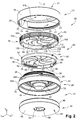
- the housing 10 comprises an opening-closing device 60 intended to close, seal, the cavity 30 containing the powdery cosmetic product P.
- the opening-closing device 60 is configured to selectively deliver said powdery cosmetic product P.
- the opening-closing device 60 comprises at least first means 62 which are integral with the base 14, here with the body 28 of the base 14.
- the first means 62 of the opening-closing device 60 comprise first orifices 64 which are in communication with said cavity 30.
- the opening-closing device 60 comprises at least second means 66 which are complementary to said first means 62.
- the second means 66 of the opening-closing device 60 comprise second orifices 68 which are capable of being placed totally or partially in communication with the first orifices 64 in order to make said powdery cosmetic product P accessible.
- the first orifices 64 pass axially through the first membrane 70 and the second orifices 68 pass axially through the second membrane 72.
- the flat portions of the bellows supporting the product P are oriented parallel to the membranes 70, 72.
- the orifices 64 and 68 are therefore located directly opposite the product P contained in the bellows.
- the opening-closing device 60 is of the rotary type.
- the second means 66 are mounted so as to be able to rotate relative to the first means 62 between at least one closed position and one position of use.
- the closed position is a position in which the second orifices 68 are angularly offset along the axis O with respect to the first orifices 64 in order to close the passage of the pulverulent cosmetic product P contained in the cavity 30.
- the position of use is a position in which the second orifices 68 are axially superimposed on the first orifices 64 to allow the passage of the pulverulent cosmetic product P contained in the cavity 30.
- the second means 66 of the opening-closing device 60 are capable of occupying at least one intermediate position between the closed position and the position of use.
- an intermediate position is a position in which the second orifices 68 are partially superimposed on the first orifices 64.
- the second means 66 of the opening-closing device 60 are able to occupy several intermediate positions, freely determined by the user.
- the second orifices 68 are aligned axially with respect to the first orifices 64 while, in the intermediate position, the second orifices 68 are only partially aligned axially with respect to said first orifices 64.
- the opening-closing device 60 is further characterized in that the first means 62 comprise at least a first flexible membrane 70 and the second means 66 comprise at least one second flexible membrane 72.
- the second flexible membrane 72 is intended to be arranged axially above the first flexible membrane 70, superimposed on said first membrane 70.
- first flexible membrane 70 and the second flexible membrane 72 are respectively configured to deform at least axially, in particular under the action of an applicator, such as a brush or a sponge.
- the first flexible membrane 70 and the second flexible membrane 72 by deforming axially, allow said powdery cosmetic product P to be taken freely and directly.
- the powdery cosmetic product P is for example taken from the second orifices 68 of the second membrane 72, brought completely or partially into coincidence with the first orifices 64 of the first membrane 70, passing on the surface and / or through said second orifices. 68 depending on the type of applicator used.
- the first flexible membrane 70 and the second flexible membrane 72 are made of an elastomeric material.
- the first flexible membrane 70 and the second flexible membrane 72 are made from the same elastomeric material, alternatively from different materials.
- the first flexible membrane 70 and / or the second flexible membrane 72 are made of silicone.
- first orifices 64 of the first flexible membrane 70 and the second orifices 68 of the second flexible membrane 72 are configured to increase the elasticity of said first and second membranes 70 and 72, so as to increase their capacity for elastic deformation, in particularly in use under the action of an applicator.
- first orifices 64 and the second orifices 68 have a non-cylindrical shape.
- the first orifices 64 and the second orifices 68 are identical.
- first orifices 64 and the second orifices 68 are different.
- first orifices 64 and the second orifices 68 have a non-rectilinear shape, in particular curved or curved.
- first orifices 64 and the second orifices 68 extend radially and preferably have a surface which increases radially from the inside to the outside.
- the first orifices 64 and the second orifices 68 are formed by slits.
- the first orifices 64 and the second slit-shaped orifices 68 extend radially from a central portion of the membrane towards its outer periphery.
- the slots forming the first orifices 64 and the second orifices 68 extend radially from the inside to the outside in a non-rectilinear manner.
- first orifices 64 of the first flexible membrane 70 and the second orifices 68 of the second flexible membrane 72 are respectively configured so as to increase the flexibility of said first and second membranes 70 and 72.
- the presence of non-rectilinear slits contributes to obtaining better flexibility over the assembly of the first flexible membrane 70 and of the second flexible membrane 72 due to a deformation axis D associated with each slit when, during in use, a pressing applicator axially deforms said membranes 70 and 72 in the direction of cavity 30.
- the slots forming the first orifices 64 and the second orifices 68 extend radially along a curvilinear, curved or curved path, each having for example the shape of one of the blades of a propeller.
- the slits forming the first orifices 64 and the second orifices 68 extend radially from the central part of the membrane while widening, thus presenting a surface which increases radially from the inside to the outside.
- the slots each having the shape of a propeller blade combining a curvilinear path and such a widening retain this propeller blade shape throughout the opening and closing of the opening-closing device 60. , that is to say that in one direction as in the other, said slots forming the first orifices 64 and the second orifices 68 retain said propeller blade shape during their progressive superposition and as illustrated by figure 6 .
- the first orifices 64 of the first membrane 70 and the second orifices 68 of the second membrane 72 are distributed angularly in a regular manner around the axis O.
- the first membrane 70 comprises a number N of first orifices 64, for example here an odd number N which is equal to nine.
- the second membrane 72 has the same number N of second orifices 64.
- the number N of orifices 64, 68 is an even or odd number, preferably between 4 and 12, advantageously between 6 and 9.
- Said number N is in particular determined as a function of the dimensions of the first membrane 70 and of the second membrane 72, of those of the first orifices 64 and of second orifices 68, in particular of their geometric shape.
- each first orifice 64 is positioned between two second consecutive orifices 68 of the second membrane 72.
- the number N of orifices 64 and 68 is further determined so that, in the closed position, a part of the first membrane 70 and of the second membrane 72 form a strip of material separating the first orifices 64 from said second orifices 68. in order to guarantee optimal obturation.
- the first flexible membrane 70 has an upper face 74 and a lower face 76 while the second membrane 72 has an upper face 78 and a lower face 80.
- first membrane 70 and the second membrane 72 are in contact with each other in the closed position and in the use position, via the upper face 74 in contact with the lower face 80.
- the first means 62 of the opening-closing device 60 comprise a fixed ring 82 to which said first flexible membrane 70 is integral.
- the fixed ring 82 and the first flexible membrane 70 are obtained by overmolding, in particular by bi-material injection.
- the fixed ring 82 comprises a wall 84 which extends radially and a wall 86 which extends axially downwards, in the extension of the wall 84, each of said walls 84 and 86 being circumferentially continuous.
- the fixed ring 82 has in section, by a vertical plane passing through the main axis O, a lying “L” shape.
- the first membrane 70 is integral with the free end of the radial wall 84 of the fixed ring 82.
- the axial wall 86 comprises, at its free axial end, an edge 85 which is positioned, after mounting the fixed ring 82, above the shoulder 36 of the body 28 of the base 14 which extends radially.
- the edge 85 has after assembly a clearance relative to the shoulder 36 of the body 28 due to the manufacturing tolerances of the plastic parts.
- the fixed ring 82 is mounted integral with the body 28 of the base 14 by elastic interlocking.
- the fixed ring 82 is mounted integral with the body 28 of the base 14 by any other equivalent fixing means, such as by gluing, by welding.
- the fixed ring 82 and the body 28 of the base 14 are parts made of plastic.
- the choice of the fixing means is therefore determined in particular as a function of the plastic material used respectively for the fixed ring 82 and the body 28 of the base 14.
- the wall 86 of the fixed ring 82 comprises an internal face 88 comprising beads 90 which extend radially projecting from said internal face 88.
- the beads 90 illustrated on the figure 2 However, they only constitute a non-limiting example of axial locking means for axially connecting the ring 82 fixed to the body 28 of the base 14, here by elastic interlocking.
- the fixed ring 82 comprises three beads 90 which are distributed circumferentially in a regular manner with respect to the axis O, that is to say distributed at 120 °.
- each bead 90 engages radially under the toothed ring 38 so as to axially block the ring 82 fixed to the body 28 of the base 14.
- the fixed ring 82 of the opening-closing device 60 being elastically fitted, said ring 82 is axially locked but not locked in rotation with respect to the base 14.
- the fixed ring 82 and the body 28 of the base 14 respectively comprise complementary means intended to ensure, by cooperation of shapes, a rotational locking of said ring 82 relative to the body 28 of the base 14.
- the fixed ring 82 comprises for example at least one rib 92, preferably ribs 92 which extend axially and radially projecting from said internal face 88.
- the fixed ring 82 comprises a pair of ribs 92 between two consecutive beads 90, so that the ring 82 comprises three pairs of ribs 92 which are distributed angularly in a regular manner around the axis O, ie at 120 °.
- the ribs 92 are intended to cooperate with the toothed ring 38 to ensure a rotational locking of the ring 82 fixed relative to the body 28 of the base 14.
- the fixed ring 82 comprises at least one pin 94, here three pins 94 distributed angularly in a regular manner around the axis O, ie at 120.
- the pins 94 (the function of which will be described later) have, for example, a cylindrical section and extend radially projecting from the wall 86.
- the second means 66 of the opening-closing device 60 comprise a rotating ring 96 to which the second flexible membrane 72 is integral.
- the rotating ring 96 comprises a wall 98 which extends radially and a wall 100 which extends axially downwards in the extension of the wall 98, each of said walls 98 and 100 being circumferentially continuous.
- the rotating ring 96 has in section, by a vertical plane passing through the main axis O, a lying “L” shape.
- the wall 100 comprises an outer surface 102 which is ridged (or knurled) so as to facilitate the gripping of the rotating ring 96 during rotational drive manipulations between the closed position and the position of use and reciprocally.
- the wall 98 comprises on the upper surface at least one marking 104, for example at least one arrow and a pictogram representing an open padlock, in order to indicate the direction of rotation of the rotating ring 96 to drive it from the position shutter to the position of use.
- the closing of the cavity 30 by means of the opening-closing device 60 is obtained by driving the rotating ring 96 clockwise to move it from the position of use or an intermediate position to another intermediate position or the closed position.
- the direction of rotation of the rotating ring 96 between the position of use and the closed position is the same as that of the cover 12 between the open position and the closed position.
- the axial wall 100 comprises, at its free axial end, an edge 105 which is capable of cooperating, after mounting the rotating ring 96, with the shoulder 36 of the body 28 of the base 14 extending radially.
- the second membrane 72 is integral with the free end of the radial wall 98 of the rotating ring 96.
- the rotating ring 96 and the second flexible membrane 72 are obtained by overmolding, in particular by bi-material injection.
- the fixed ring 82 is firstly mounted on the body 28 of the base 14 before inserting the rotating ring 96 of the opening-closing device 60.
- the fixed ring 82 and the rotating ring 96 of the opening-closing device 60 are previously mounted to form a unitary sub-assembly.
- the opening-closing device 60 formed by said unitary sub-assembly comprising the membranes 70, 72 is then mounted on the base 14, here by elastic interlocking, in particular after having filled said cavity 30 with pulverulent cosmetic product P.
- the assembly of the opening-closing device 60 is obtained by elastic interlocking of said fixed ring 82 on the crown 66 of the body 28 of the base 14.
- the fixing of the opening-closing device 60 on the base 14 by elastic interlocking is not reversible.
- the opening-closing device 60 is reversibly fixed on the base 14 in order to allow it to be dismantled with the particular aim of being able to reload the cavity 30 with powdery cosmetic product P.
- the opening-closing device 60 of the housing 10 comprises connecting means configured to connect axially, preferably without play, the rotating ring 96 to the fixed ring 82, leaving the rotating ring 96 free to rotate with respect to said said ring. fixed ring 82.
- the stationary ring 82 is designed to be mounted axially within the rotating ring 96.
- the fixed ring 82 has an outer diameter which is substantially equal to the inner diameter of the rotating ring 96.
- the connecting means comprise on the one hand at least one male element formed by said pins 94 which are integral with the fixed ring 82.
- the connecting means also comprise at least one female element formed by grooves 106 which, carried by the rotating ring 96, are respectively associated with the pins 94.
- the grooves 106 are made hollow in an internal face 109 of the wall 100 of the rotating ring 96, three in number of said grooves 106 are distributed circumferentially in a regular manner around the axis O, ie at 120 °.
- the three grooves 106 are identical so that the following description of one more particularly visible on the figure 2 the same applies to the other two.
- Each groove 106 comprises successively, in an "L" shape, at least one section 108 for mounting the pin 94 which extends axially and a section 110 for guiding the pin 94 which extends circumferentially in a radial plane, orthogonal to the axial direction determined by the main axis O.
- the assembly of the fixed ring 82 with the rotating ring 96 is a so-called "bayonet" assembly.
- the mounting of the fixed ring 82 with the rotating ring 96 is obtained by axially introducing each of the pins 94 into the mounting section 108 of one of the grooves 106 which is traversed in a translational movement before engaging, following a movement rotation, each pin 94 in the guide section 110 of the groove 106.
- the assembly section 108 has an entrance which is flared to facilitate the introduction of said pin 94.
- the assembly section 108 is connected to the guide section 110 following an elbow generally at right angles.
- the guide section 110 comprises a lug 112 which, formed at the start of said guide section 110 of the groove 106, is forcefully crossed by the pin 94.
- said lug 112 makes it possible in particular to produce a captive assembly thanks to which the pin 94 is then held in the associated groove 106.
- the connecting means comprising the pins 94 and the associated grooves 106 are configured to integrate various functions which ensure correct operation of the opening-closing device 60.
- One of these functions is a function of guiding in rotation between the fixed ring 82 and the rotating ring 96 of the opening-closing device 60.
- the guide section 110 of the groove 106 comprises guide surfaces, respectively an upper surface 114 and a lower surface 116, intended to cooperate with said pin 94.
- Another of the functions is a positioning function with stop means which respectively determine the closed position and the position of use, the two extreme positions of the rotating ring 96 of the opening-closing device 60.
- the guide section 110 of the groove 106 comprises at least a first stop face 118 and a second stop face 120 which, intended to cooperate with the pin 94, extend axially.
- the first stop face 118 determines the position of use and the second stop face 120 determines the closed position.
- the stroke of the rotating ring 96 between the closed position and the position of use can for example be expressed in degrees, by an angle extending circumferentially between the first stop face 118 and the second face 120 and centered on the O axis.
- the first stop face 118 is formed by the end of the guide section 110.
- the second stop face 120 is carried by the lug 112 extending projecting in the guide section 110 of the groove 106.
- Another function is a function of temporary spacing of the second membrane 72 relative to the first membrane 70 in order to avoid any friction between them during the actuation of the rotating ring 96.
- first flexible membrane 70 and the second flexible membrane 72 are advantageously in contact with each other in the closed position and in the use position.
- the housing 10 comprises spacer means configured to axially cause a displacement of the rotating ring 96 relative to the fixed ring 82 according to an up-and-down movement when said rotating ring 96 is rotated between the position d obturation and the position of use and vice versa.
- the spacing means operating according to said up-and-down movement make it possible to create an axial clearance "j" between the upper face 74 of the first membrane 70 and the lower face 80 of the second membrane 72 when the rotating ring 96 is actuated in one direction or the other.
- the spacing means are formed by the upper face 114 and the lower face 116 of the guide section 110 of the groove 106 with which the pin 94 cooperates to perform the guiding function.
- the faces 114 and 116 for guiding the groove 106 each have a profile configured to axially cause said upward and downward movement of the rotating ring 96 relative to the fixed ring 82.
- each pin 94 will cooperate with the convex profile of the upper guide face 114 114, the lower face 116 exhibiting by symmetry a concave profile.
- the housing 10 is used with an opening-closing device 60 occupying the position of use preferably in the intermediate position so as to prevent powdery cosmetic product P from interfering between the first membrane 70 and the second membrane 72.
- the opening-closing device 60 comprises first sealing means 122 configured to provide sealing between said first means 62 and second means 66.
- the first flexible membrane 70 of the opening-closing device 60 comprises said first sealing means 122 intended to cooperate with the second flexible membrane 72.
- the first sealing means 122 are made integrally, in a single piece, with the first flexible membrane 70.
- the first flexible membrane 70 comprises at least one sealing ring forming said first sealing means 122.
- the sealing ring 122 extends axially projecting from the upper face 74 of the first membrane 70.
- the sealing ring 122 is arranged at the radial periphery of the first membrane 70, delimiting a perimeter inside which the first orifices 64 are arranged.
- the sealing ring 122 is intended to cooperate with the lower face 80 of the second membrane 72, at least in the position of use and in the closed position as illustrated in the figure. figure 3 .
- the first sealing means 122 make it possible to prevent powdered cosmetic product P from escaping radially and in particular from interfering between the fixed ring 82 and the rotating ring 96.
- the opening-closing device 60 comprises second sealing means 124 configured to seal the housing 10 in the closed position.
- the second flexible membrane 72 of the opening-closing device 60 comprises said second sealing means 124 intended to cooperate with the cover 12 of the housing 10 in the closed position.
- the second sealing means 124 are made integrally, in a single piece, with the second flexible membrane 72.
- the second flexible membrane 72 comprises at least one sealing ring forming said second sealing means 124.
- the sealing ring 124 extends axially projecting from the upper face 78 of the second membrane 72.
- the sealing ring 124 is arranged at the radial periphery of the second membrane 72, delimiting a perimeter inside which the second orifices 68 are arranged.
- the sealing ring 124 is intended to cooperate with the lower face 20 of the cover 12 in the closed position.
- the spacing means operating according to said up-and-down movement allow, by creating an axial clearance "j" between the upper face 74 of the first membrane 70 and the lower face 80 of the second membrane 72 when the ring 96 rotating is actuated in the opening direction, to release the sealing ring 124 and to facilitate rotation from the closed position to the position of use.
- the centralizer 22 of the cover 12 participates, in the closed position, in the centering of the sealing ring 124 surrounding it, thanks to which a good seal is obtained during cooperation with the inner face 20 of the cover 12.
- said centralizer 22 comprises a lower face 126 which is intended to cooperate, to be in contact, with the upper face 78 of the second membrane 72 so as to limit any axial movement thereof, in particular during transport.
- the dispersion of the pulverulent cosmetic product P is very limited so that the housing 10 exhibits good hygiene (or cleanliness).
- all of said sealing means 122, 124 and the centralizer 22 make it possible at the very least to limit the dispersion of the pulverulent cosmetic product P outside the housing 10 in the closed position, for example during transport.
- the user When the user wishes to apply makeup with the pulverulent cosmetic product P contained in the cavity 30 of the base 14 of the housing 10, the user first of all opens the housing 10, in this first embodiment by unscrewing the cover 12.
- the rotating ring 96 of the opening-closing device 60 is thus driven in rotation, around the axis O, relative to the base 14 of the housing 10 so as to pass from the closed position ( figure 5 ) to the intermediate position ( figure 6 ) or the position of use ( figure 7 ).
- the second orifices 68 of the second membrane 72 are axially aligned with the first orifices 64 of the first membrane 70, said first orifices 64 and second orifices 68 being identical.
- the powdery cosmetic product P such as loose powder, contained in the cavity 30 of the base 14 is then directly accessible through the second orifices 68 positioned directly above said first orifices 64.
- the user can then take the powdery cosmetic product P using an applicator, such as a brush or even a sponge.
- an applicator such as a brush or even a sponge.
- the outside diameter of the second flexible membrane 72 (and here of the first flexible membrane 70) is greater than 0.75 times the outside diameter of the base 14 of the housing 10 so as to offer a large and wide sampling surface. the user.
- the gestures of using an applicator are therefore advantageously ample and pleasant for the user.
- the applicator being in contact with the upper face 78 of the second membrane 72, the user applies a force using the applicator which axially causes a joint deformation of the second membrane 72 and of the first membrane 70, respectively. flexible or flexible.
- the elastic deformation capacity of the second membrane 72 and of the first membrane 70 is also determined by the elastomeric material used for their manufacture by overmolding, in particular by bi-material injection, respectively with the rotating ring 96 and the fixed ring 82.
- the elastomeric material is silicone and the same material is used for the second membrane 72 and the first membrane 70.
- first orifices 64 and the second orifices 68 respectively in the form of slots extend radially and by widening from the center of each of the membranes 70 and 72 towards the outside.
- the slots forming the first orifices 64 and the second orifices 68 are curved.
- the first orifices 64 and the second orifices 68, each perforating the first membrane 70 and the second membrane 72 respectively, will advantageously increase their capacity for elastic deformation.
- the axial force applied by means of the applicator on the upper face 78 of second membrane 72 is produced in combination with a clockwise rotational movement, that is to say in the direction of inclination of the orifices 64 and 68 in the form of slots.
- the powdery cosmetic product P is then taken up by the applicator passing at the level of the openings formed by the second orifices 68 aligned with the first orifices 64, taken superficially in particular when the applicator is a sponge and / or partly through said orifices. 68 and 64 in particular when the applicator is a brush.
- the dispersion is limited by the parts of said membranes 70 and 72 which, extending between the first orifices 64 and the second orifices 68, form a barrier to the passage of the product P.
- the axial pressure exerted locally on the first flexible membrane 70 and the second flexible membrane 72 by the applicator represented by an arrow on the figure 8 causes in the contact zone their respective axial deformation in the direction of the cavity which deformation is accompanied by a phenomenon of "closing" of the non-rectilinear slots located radially opposite said contact zone shown schematically in dotted lines on the figure 9 .
- the slits will stretch radially due to the deformation of each of the flexible membranes 70 and 72 and thereby narrow, their radial edges approaching.
- this phenomenon of "closing" of the slits more particularly illustrated on the figure 9 take part in limit the dispersion of the pulverulent cosmetic product P in the areas not used by the applicator.
- the slits forming the first orifices 64 and the second orifices 68 offer the user a surface for removing the cosmetic product P which is much larger. , and that in position of use as in intermediate position.
- the surface for sampling the cosmetic product P extends radially over almost the entire diameter of the opening-closing device 60 comprising the first flexible membrane 70 and the second flexible membrane 72 and is in particular not only localized. In the center.
- the first sealing means 122 formed by the annular ring of the first membrane 70 make it possible to prevent, when using the housing 10 as during transport, that the powdery cosmetic product P does not spread radially, in particular between the fixed ring 82 and the rotating ring 96.
- the housing 10 exhibits good hygiene (or cleanliness) in particular during its use.
- the user When the user has finished putting on makeup, the user actuates the rotating ring 96 of the opening-closing device 60 to return to the closed position.
- the first orifices 64 are angularly offset with respect to the second orifices 68, the first membrane 70 and the second membrane 72 then completely close the opening 44 of the part 40, isolating the cavity 30 containing the cosmetic product P. powdery.
- the second sealing means 124 formed by the annular ring of the second membrane 72 cooperate with the lower face of the cover 12 so as to isolate in particular the opening-closing device 60 from the outside of the housing 10.
- Powdered cosmetic product P possibly present at the level of the upper face 78 of the second membrane 72 following the use of the housing 10 is therefore not able to spread outside the housing 10.
- the housing 10 Compared to the housings of the prior art, the housing 10 exhibits good hygiene (or cleanliness) and can be transported, for example in a bag, without this then causing problems of dispersion of the product P.
- the transparent cover 12 is fixed on the base 14 by screwing as in the first embodiment.
- the opening-closing device 60 is identical to that of the first embodiment and will therefore not be described in detail.
- the base 14 is made in two parts, respectively the body 28 and the bottom 32.
- the body 28 of the base 14 does not include a part 40 in the form of a bellows.
- the bottom 32 is modified accordingly and differs from that of the first embodiment in that it does not include in particular any opening 52 or even partitions 54, 56.
- the bottom 32 is structurally simplified.
- the cavity 30 is produced integrally, in a single piece, with the body 28 of the base 14.
- the cavity 30 of the housing 10 according to this second embodiment has a volume which is less than that obtained with the flexible part 40 in the form of a bellows.
- a housing 10 according to one or the other of said embodiments will be chosen in particular as a function of the desired content of powdery cosmetic product P.
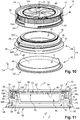
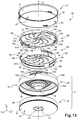
- the cover 12 is here not fixed on the base 14 by screwing but by a bayonet mounting.
- the cover 12 comprises at least one finger 128 which projects radially inwardly projecting from the internal face 23 of the axial wall 18.
- the cover 12 comprises three fingers 128 which are distributed angularly in a regular manner around the axis O, that is to say at 120 °, as illustrated in the figures. figures 12 and 13 with the transparency of the cover.
- the base 14 made in two parts comprises a body 28 and a bottom 32.
- the body 28 comprises a part 40 in the form of a bellows which delimits the cavity 30 intended to receive the powdery cosmetic product P.
- the body 28 has a wall 34 which, extending axially, is stepped.
- the wall 34 successively comprises bottom up a lower section 34A, an intermediate section 34B and an upper section 34C.
- the upper section 34C of the wall 34 of the body 28 of the base 14 does not have a toothed crown 38.
- the fixed ring 82 comprises at least one boss, here three bosses 130 which are distributed at 120 ° and which project radially from the internal face 88 of the axial wall 86 of said fixed ring 82.
- the three bosses 130 are each intended to cooperate with a complementary indentation 132 integral with the upper section 34C of the wall 34 of the body 28 of the base 14.
- angular indexing is necessary here during the mounting of the fixed ring 82 on the body 28 of the base 14, the bosses 130 having to be axially aligned with the recesses 132.
- the housing 10 comprises keying means configured to allow closing of the cover 12 of the housing 10 only when the opening-closing device 60 occupies the closed position.
- the rotating ring 96 of the opening-closing device 60 comprises three notches 134 which, formed in the wall 100, are distributed angularly in a regular manner like the fingers 128 of the cover 12.
- the fixed ring 82 comprises three studs 136 which project radially outwardly from the wall 86.
- the rotating ring 96 comprises cutouts 138, open axially downwards, which are each intended to receive one of the studs 136 of the fixed ring 82 after their assembly to obtain a unitary sub-assembly.
- the cutouts 138 are configured to allow the rotation of the rotating ring 96 relative to the fixed ring 82 during actuation of said rotating ring 96 between the closed and use positions of the opening-closing device 60.
- Each pad 136 has a notch 140 so that the pad 136 has a stepped profile circumferentially.
- the notches 134 and 140 constitute said keying means intended to selectively allow the axial passage of the fingers 128 during handling of the cover 12 in order to open or close the housing 10.
- the body 28 of the base 14 comprises three grooves 142 which, associated with the fingers 128, are formed in the body 28 of the base 14, here in the outer surface of the intermediate section 34B of the wall 34.
- each groove 142 comprises a first introductory section 144 which is then extended by a second closing section 146.
- the first section 144 of the groove 142 is open axially upwards to allow the introduction (or the withdrawal) of the finger 128 of the cover 12.
- the second section 146 for closing the groove 142 extends circumferentially in the wall 34, obliquely.
- a locking lug 148 is arranged in the second section 146 for closing the groove 142.
- the locking lug 148 makes it possible to block the finger 128 at the end of its travel when the cover 12 is in the closed position, whereby any unexpected opening of the housing 10 is avoided, in particular during transport.
- the crossing of the lug 148 by the finger 128 is accompanied by a resistance requiring a slight additional effort thanks to which the information of locking or unlocking is given to the user.
- the cover 12 is moved axially relative to the body 28 of the base 14 in a translational movement.
- the notch 134 of the rotating ring 96 is then axially aligned with the notch 140 of the fixed ring 82.
- the notch 140 of the fixed ring 82 is also axially aligned with the first section 144 for introducing the groove 142 so that the finger 128 is then introduced into said groove 142 as illustrated in FIG. figure 15 .
- the cover 12 is then driven around the axis O following a rotational movement so as to engage the finger 128 in the second section 146 for closing the groove 142, here until it passes through the locking lug 148, to reach the closed position shown on the figure 16 .
- the notch 134 of the rotating ring 96 is not axially aligned with the notch 140 of the fixed ring 82.
- the notch 134 of the rotating ring 96 is axially aligned with the stud 136 which is configured to axially block the passage of the finger 128.
- the cover 12 cannot therefore close the base 14 of the housing 10 because the stud 136 interposed between the notch 134 and the first section 144 introduction of the groove 142 obstructs the passage of the finger 128.
- the keying means make it possible to guarantee that, with the housing 10 being closed by the cover 12, the cavity 30 is properly closed by the opening-closing device 60 so as to avoid any unexpected dispersion of the powder cosmetic product P that may occur. through the membranes in the use position.
- the sealing means formed by the rods 122 and 124 of the membranes 70 and 72 also make it possible to prevent the dispersion of the pulverulent cosmetic product P and to obtain a housing 10 exhibiting good hygiene ( or cleanliness).
Landscapes
- Engineering & Computer Science (AREA)
- Mechanical Engineering (AREA)
- Containers And Packaging Bodies Having A Special Means To Remove Contents (AREA)
- Cosmetics (AREA)
Claims (15)
- Gehäuse (10) für ein pulverförmiges Kosmetikprodukt (P), das mindestens einen Deckel (12) und eine Basis (14) umfasst, die zueinander zwischen mindestens einer geschlossenen Position und einer offenen Position des Gehäuses (10) beweglich montiert sind, wobei die Basis (14) einen Hohlraum (30) umfasst, der dazu bestimmt ist, das pulverförmige Kosmetikprodukt (P) aufzunehmen, der von einer Öffnungs-Schließvorrichtung (60) verschlossen ist, die dazu konfiguriert ist, selektiv das pulverförmige Kosmetikprodukt (P) zu liefern, wobei die Öffnungs-Schließvorrichtung (60) mindestens erste Mittel (62) umfasst, die, indem sie erste Öffnungen (64) in Verbindung mit dem Hohlraum (30) umfassen, fest mit der Basis (14) verbunden sind, und zweite Mittel (66), die, indem sie zweite Öffnungen (68) umfassen, in Drehung in Bezug auf die ersten Mittel (62) zwischen mindestens einer Verschlussposition und einer Verwendungsposition beweglich montiert sind, dadurch gekennzeichnet, dass die ersten Mittel (62) mindestens eine erste biegsame Membran (70) umfassen, und die zweiten Mittel (66) mindestens eine zweite biegsame Membran (72) umfassen.
- Gehäuse nach Anspruch Anspruch 1, dadurch gekennzeichnet, dass mindestens eine der ersten Öffnungen (64) die erste Membran (70) axial durchquert, und mindestens eine der zweiten Öffnungen (68) die zweite Membran (72) axial durchquert.
- Gehäuse nach einem der vorstehenden Ansprüche, dadurch gekennzeichnet, dass mindestens eine der ersten Öffnungen (64) der ersten biegsamen Membran (70) und mindestens eine der zweiten Öffnungen (68) der zweiten biegsamen Membran (72) eine nicht zylindrische Form aufweisen.
- Gehäuse nach einem der Ansprüche 2 oder 3, dadurch gekennzeichnet, dass mindestens eine der ersten Öffnungen (64) der ersten biegsamen Membran (70) und mindestens eine der zweiten Öffnungen (68) der zweiten biegsamen Membran (72) eine nicht geradlinige, insbesondere gekrümmte oder einwärts gekrümmte Form aufweisen.
- Gehäuse nach einem der vorstehenden Ansprüche, dadurch gekennzeichnet, dass mindestens eine der ersten Öffnungen (64) der ersten biegsamen Membran (70) und mindestens eine der zweiten Öffnungen (68) der zweiten biegsamen Membran (72) eine Oberfläche, die radial von innen nach außen zunimmt, aufweisen.
- Gehäuse nach einem der vorstehenden Ansprüche, dadurch gekennzeichnet, dass mindestens eine der ersten Öffnungen (64) der ersten biegsamen Membran (70) und mindestens eine der zweiten Öffnungen (68) der zweiten biegsamen Membran (72) jeweils eine Form von Schlitzen aufweisen.
- Gehäuse nach einem der vorstehenden Ansprüche, dadurch gekennzeichnet, dass die ersten Öffnungen (64) der ersten biegsamen Membran (70) und die zweiten Öffnungen (68) der zweiten biegsamen Membran (72) jeweils dazu konfiguriert sind, eine freie Menge an pulverförmigem Kosmetikprodukt (P) mittels eines Applikators durch die zweiten Öffnungen (68) der zweiten Membran (72), die vollständig oder teilweise mit den ersten Öffnungen (64) der ersten Membran (70) übereinstimmen, zu entnehmen.
- Gehäuse nach einem der vorstehenden Ansprüche, dadurch gekennzeichnet, dass die ersten Öffnungen (64) der ersten biegsamen Membran (70) und die zweiten Öffnungen (68) der zweiten biegsamen Membran (72) jeweils dazu konfiguriert sind, die Biegsamkeit der ersten Membran (70) und der zweiten Membran (72) zu erhöhen.
- Gehäuse nach einem der vorstehenden Ansprüche, dadurch gekennzeichnet, dass die erste biegsame Membran (70) und die zweite biegsamen Membran (72) aus einem Elastomermaterial, insbesondere aus Silikon, hergestellt sind.
- Gehäuse nach einem der vorstehenden Ansprüche, dadurch gekennzeichnet, dass die erste Membran (70) und die zweite Membran (72) miteinander in Verschlussposition und in Verwendungsposition in Berührung stehen.
- Gehäuse nach einem der vorstehenden Ansprüche, dadurch gekennzeichnet, dass der Hohlraum (30) zu einem biegsamen Teil (40), das fest mit der Basis (14) verbunden ist, gehört, wobei das Teil (40) insbesondere eine Balgform aufweist.
- Gehäuse nach einem der vorstehenden Ansprüche, dadurch gekennzeichnet, dass die ersten Mittel (62) der Öffnungs-Schließvorrichtung einen stationären Ring (82), der fest mit der ersten biegsamen Membran (70) verbunden ist, umfassen.
- Gehäuse nach dem vorstehenden Anspruch, dadurch gekennzeichnet, dass der stationäre Ring (82) axial auf einem Körper (28) der Basis (14) durch elastisches Einrasten montiert ist, und dass der stationäre Ring (82) in Drehung durch Zusammenwirken von Formen in Bezug auf den Körper (28) der Basis (14) blockiert ist.
- Gehäuse nach einem der vorstehenden Ansprüche, dadurch gekennzeichnet, dass die zweiten Mittel (66) der Öffnungs-Schließvorrichtung mindestens eine Zwischenposition zwischen der Verschlussposition und der Verwendungsposition belegen können, in der die zweiten Öffnungen (68) teilweise auf den ersten Öffnungen (64) überlagert sind.
- Gehäuse nach einem der vorstehenden Ansprüche, dadurch gekennzeichnet, dass die zweiten Mittel (66) der Öffnungs-Schließvorrichtung einen drehenden Ring (96), mit dem die zweite biegsame Membran (72) fest verbunden ist, umfassen.
Applications Claiming Priority (1)
| Application Number | Priority Date | Filing Date | Title |
|---|---|---|---|
| FR1859365A FR3086850B1 (fr) | 2018-10-09 | 2018-10-09 | Boitier pour produit cosmetique pulverulent comportant un dispositif d'ouverture-fermeture perfectionne |
Publications (2)
| Publication Number | Publication Date |
|---|---|
| EP3636100A1 EP3636100A1 (de) | 2020-04-15 |
| EP3636100B1 true EP3636100B1 (de) | 2021-08-25 |
Family
ID=65244214
Family Applications (1)
| Application Number | Title | Priority Date | Filing Date |
|---|---|---|---|
| EP19201239.1A Active EP3636100B1 (de) | 2018-10-09 | 2019-10-03 | Behälter für pulverförmiges kosmetikprodukt, der eine verbesserte öffnungs-/schliessvorrichtung umfasst |
Country Status (4)
| Country | Link |
|---|---|
| US (1) | US20210106115A1 (de) |
| EP (1) | EP3636100B1 (de) |
| CN (1) | CN111017398A (de) |
| FR (1) | FR3086850B1 (de) |
Families Citing this family (5)
| Publication number | Priority date | Publication date | Assignee | Title |
|---|---|---|---|---|
| FR3109509B1 (fr) | 2020-04-24 | 2022-05-06 | Oreal | Dispositif de conditionnement de produit cosmétique |
| CN112776715A (zh) * | 2021-01-13 | 2021-05-11 | 广州驰享汽车用品有限公司 | 一种房车监控系统 |
| FR3128858B1 (fr) * | 2021-11-09 | 2025-04-04 | Albea Services | Boîtier rechargeable pour produit cosmetique pulverulent |
| FR3128857B1 (fr) * | 2021-11-09 | 2023-09-29 | Albea Services | Boîtier autonettoyant pour produit cosmetique pulverulent |
| US12426697B2 (en) * | 2022-05-12 | 2025-09-30 | Crystal International (Group), Inc. | Free flow powder container |
Family Cites Families (19)
| Publication number | Priority date | Publication date | Assignee | Title |
|---|---|---|---|---|
| US1690275A (en) * | 1925-06-26 | 1928-11-06 | Scovill Manufacturing Co | Vanity case |
| US1631964A (en) * | 1926-03-30 | 1927-06-14 | Majestic Metal Specialties Inc | Vanity case |
| FR685857A (de) * | 1928-05-05 | 1930-08-13 | ||
| US1858218A (en) * | 1929-11-02 | 1932-05-10 | Friedman William | Toilet accessory |
| US7494030B2 (en) * | 2005-06-14 | 2009-02-24 | Rexam Beauty And Closures, Inc. | Sifter device for container |
| US20080178903A1 (en) * | 2007-01-25 | 2008-07-31 | Timothy Thorpe | Rotating Sifter |
| CN201042268Y (zh) * | 2007-06-06 | 2008-04-02 | 殷昌(苏州)包装有限公司 | 结构改进的化妆粉饼盒 |
| US8025067B2 (en) * | 2008-01-29 | 2011-09-27 | HCT Asia, Ltd | Displacement sifter |
| US8678222B2 (en) * | 2010-04-30 | 2014-03-25 | Hct Asia Ltd | Airtight compact |
| US20120103986A1 (en) * | 2010-11-02 | 2012-05-03 | Ching-Te Wang | Powder Container That Will Prevent A User's Hand From Touching The Powder Directly |
| CN202222667U (zh) * | 2011-09-15 | 2012-05-23 | 张家声 | 蜜粉盒出料自动启闭结构改良 |
| CN104757772A (zh) * | 2015-03-30 | 2015-07-08 | 杨振波 | 一种液体粉饼盒 |
| CN205410179U (zh) * | 2015-12-03 | 2016-08-03 | 简华 | 一种粉膏容器 |
| CN206166108U (zh) * | 2016-11-01 | 2017-05-17 | 东莞市玉榕包装制品有限公司 | 长寿命化妆盒 |
| CN206791963U (zh) * | 2017-03-27 | 2017-12-26 | 苏州柒久包装科技有限公司 | 气垫霜盒 |
| CN207075704U (zh) * | 2017-06-07 | 2018-03-09 | 藤兴工业有限公司 | 一种用于化妆品容器的衬盖组件 |
| CN107114899A (zh) * | 2017-06-19 | 2017-09-01 | 广州卡迪莲化妆品有限公司 | 一种气垫化妆盒内胆 |
| FR3081689B1 (fr) * | 2018-06-05 | 2021-09-17 | Albea Services | Boitier pour produit cosmetique, notamment un produit cosmetique pulverulent |
| CN108577134B (zh) * | 2018-07-03 | 2019-09-10 | 杨惠萍 | 一种化妆品营销用便于试用的散粉盒 |
-
2018
- 2018-10-09 FR FR1859365A patent/FR3086850B1/fr not_active Expired - Fee Related
-
2019
- 2019-10-03 EP EP19201239.1A patent/EP3636100B1/de active Active
- 2019-10-09 CN CN201910955677.3A patent/CN111017398A/zh active Pending
- 2019-10-09 US US16/597,788 patent/US20210106115A1/en not_active Abandoned
Also Published As
| Publication number | Publication date |
|---|---|
| FR3086850A1 (fr) | 2020-04-10 |
| EP3636100A1 (de) | 2020-04-15 |
| CN111017398A (zh) | 2020-04-17 |
| US20210106115A1 (en) | 2021-04-15 |
| FR3086850B1 (fr) | 2020-09-25 |
Similar Documents
| Publication | Publication Date | Title |
|---|---|---|
| EP3636100B1 (de) | Behälter für pulverförmiges kosmetikprodukt, der eine verbesserte öffnungs-/schliessvorrichtung umfasst | |
| EP0161980B1 (de) | Schminkeinheit, insbesondere für Augenwimpern, die eine Entnahme einer vorherbestimmten Menge vom Schminkprodukt erlaubt | |
| EP2091836B1 (de) | Flüssigproduktspender | |
| FR2750022A1 (fr) | Distributeur de produit a organe de manoeuvre rotatif et procede de fabrication | |
| EP0649795A2 (de) | Ausgabevorrichtung, versehen mit einem Rückschlagventil | |
| EP0822148A1 (de) | Behälter zur getrennten Aufbewahrung, Mischung von zwei Produkten und Ausgiessender Mischung | |
| WO1998008746A1 (fr) | Capsule de distribution a etancheite amelioree | |
| EP0893364A1 (de) | Behälter zur getrennten Aufbewahrung von zwei Produkten | |
| EP4005430A1 (de) | Mechanismus für ein kosmetikprodukt, insbesondere für eine kleine menge an lippenstift, und behälter, der einen solchen mechanismus umfasst | |
| EP4176764B1 (de) | Selbstreinigender behälter für pulverförmiges kosmetikprodukt | |
| EP3324785B1 (de) | Kosmetischer applikator mit beweglichen protuberanzen | |
| EP2178415A2 (de) | Vorrichtung für ein kosmetikprodukt mit einem tank und einem applikator | |
| EP2461716B1 (de) | Vorrichtung zur ausgabe eines kosmetikprodukts mit spenderöffnung | |
| FR2964022A1 (fr) | Essoreur pour applicateur de produit, ensemble d'application comprenant un tel essoreur, et son utilisation en cosmetique | |
| EP1362525B1 (de) | Auftragevorrichtung des Roll-on Typs | |
| FR2563712A1 (fr) | Ensemble de maquillage, notamment pour les cils, permettant de prelever une quantite predeterminee de produit de maquillage | |
| EP3324787B1 (de) | Kosmetikartikel mit beweglichem applikator | |
| FR2974352A1 (fr) | Boite de distribution, notamment pour un produit libre ou un produit liquide | |
| WO2024022604A1 (fr) | Distributeur d'un produit fluide, recharge associée et réceptacle associé | |
| WO2024022605A1 (fr) | Recharge pour réceptacle de produit fluide et réceptacle associé | |
| FR2977872A1 (fr) | Organe de bouchage et distributeur comprenant un tel organe. | |
| FR2981916A1 (fr) | Capsule de fermeture pour recipient de produit, notamment de produit cosmetique | |
| FR2843735A1 (fr) | Recipient comportant une partie de base et un capot prenant une orientation determinee lorsqu'il est mis en place sur la partie de base | |
| EP1665948A1 (de) | Spender für pastenartige oder feste Erzeugnisse | |
| FR3069140A1 (fr) | Mecanisme de came, en particulier pour un applicateur de produit cosmetique |
Legal Events
| Date | Code | Title | Description |
|---|---|---|---|
| PUAI | Public reference made under article 153(3) epc to a published international application that has entered the european phase |
Free format text: ORIGINAL CODE: 0009012 |
|
| STAA | Information on the status of an ep patent application or granted ep patent |
Free format text: STATUS: THE APPLICATION HAS BEEN PUBLISHED |
|
| AK | Designated contracting states |
Kind code of ref document: A1 Designated state(s): AL AT BE BG CH CY CZ DE DK EE ES FI FR GB GR HR HU IE IS IT LI LT LU LV MC MK MT NL NO PL PT RO RS SE SI SK SM TR |
|
| AX | Request for extension of the european patent |
Extension state: BA ME |
|
| STAA | Information on the status of an ep patent application or granted ep patent |
Free format text: STATUS: REQUEST FOR EXAMINATION WAS MADE |
|
| 17P | Request for examination filed |
Effective date: 20201015 |
|
| RBV | Designated contracting states (corrected) |
Designated state(s): AL AT BE BG CH CY CZ DE DK EE ES FI FR GB GR HR HU IE IS IT LI LT LU LV MC MK MT NL NO PL PT RO RS SE SI SK SM TR |
|
| GRAP | Despatch of communication of intention to grant a patent |
Free format text: ORIGINAL CODE: EPIDOSNIGR1 |
|
| STAA | Information on the status of an ep patent application or granted ep patent |
Free format text: STATUS: GRANT OF PATENT IS INTENDED |
|
| INTG | Intention to grant announced |
Effective date: 20210318 |
|
| GRAS | Grant fee paid |
Free format text: ORIGINAL CODE: EPIDOSNIGR3 |
|
| GRAA | (expected) grant |
Free format text: ORIGINAL CODE: 0009210 |
|
| STAA | Information on the status of an ep patent application or granted ep patent |
Free format text: STATUS: THE PATENT HAS BEEN GRANTED |
|
| AK | Designated contracting states |
Kind code of ref document: B1 Designated state(s): AL AT BE BG CH CY CZ DE DK EE ES FI FR GB GR HR HU IE IS IT LI LT LU LV MC MK MT NL NO PL PT RO RS SE SI SK SM TR |
|
| REG | Reference to a national code |
Ref country code: CH Ref legal event code: EP |
|
| REG | Reference to a national code |
Ref country code: IE Ref legal event code: FG4D Free format text: LANGUAGE OF EP DOCUMENT: FRENCH Ref country code: AT Ref legal event code: REF Ref document number: 1422894 Country of ref document: AT Kind code of ref document: T Effective date: 20210915 |
|
| REG | Reference to a national code |
Ref country code: DE Ref legal event code: R096 Ref document number: 602019007135 Country of ref document: DE |
|
| REG | Reference to a national code |
Ref country code: LT Ref legal event code: MG9D |
|
| REG | Reference to a national code |
Ref country code: NL Ref legal event code: MP Effective date: 20210825 |
|
| REG | Reference to a national code |
Ref country code: AT Ref legal event code: MK05 Ref document number: 1422894 Country of ref document: AT Kind code of ref document: T Effective date: 20210825 |
|
| PG25 | Lapsed in a contracting state [announced via postgrant information from national office to epo] |
Ref country code: SE Free format text: LAPSE BECAUSE OF FAILURE TO SUBMIT A TRANSLATION OF THE DESCRIPTION OR TO PAY THE FEE WITHIN THE PRESCRIBED TIME-LIMIT Effective date: 20210825 Ref country code: RS Free format text: LAPSE BECAUSE OF FAILURE TO SUBMIT A TRANSLATION OF THE DESCRIPTION OR TO PAY THE FEE WITHIN THE PRESCRIBED TIME-LIMIT Effective date: 20210825 Ref country code: ES Free format text: LAPSE BECAUSE OF FAILURE TO SUBMIT A TRANSLATION OF THE DESCRIPTION OR TO PAY THE FEE WITHIN THE PRESCRIBED TIME-LIMIT Effective date: 20210825 Ref country code: FI Free format text: LAPSE BECAUSE OF FAILURE TO SUBMIT A TRANSLATION OF THE DESCRIPTION OR TO PAY THE FEE WITHIN THE PRESCRIBED TIME-LIMIT Effective date: 20210825 Ref country code: LT Free format text: LAPSE BECAUSE OF FAILURE TO SUBMIT A TRANSLATION OF THE DESCRIPTION OR TO PAY THE FEE WITHIN THE PRESCRIBED TIME-LIMIT Effective date: 20210825 Ref country code: AT Free format text: LAPSE BECAUSE OF FAILURE TO SUBMIT A TRANSLATION OF THE DESCRIPTION OR TO PAY THE FEE WITHIN THE PRESCRIBED TIME-LIMIT Effective date: 20210825 Ref country code: BG Free format text: LAPSE BECAUSE OF FAILURE TO SUBMIT A TRANSLATION OF THE DESCRIPTION OR TO PAY THE FEE WITHIN THE PRESCRIBED TIME-LIMIT Effective date: 20211125 Ref country code: NO Free format text: LAPSE BECAUSE OF FAILURE TO SUBMIT A TRANSLATION OF THE DESCRIPTION OR TO PAY THE FEE WITHIN THE PRESCRIBED TIME-LIMIT Effective date: 20211125 Ref country code: PT Free format text: LAPSE BECAUSE OF FAILURE TO SUBMIT A TRANSLATION OF THE DESCRIPTION OR TO PAY THE FEE WITHIN THE PRESCRIBED TIME-LIMIT Effective date: 20211227 Ref country code: HR Free format text: LAPSE BECAUSE OF FAILURE TO SUBMIT A TRANSLATION OF THE DESCRIPTION OR TO PAY THE FEE WITHIN THE PRESCRIBED TIME-LIMIT Effective date: 20210825 |
|
| PG25 | Lapsed in a contracting state [announced via postgrant information from national office to epo] |
Ref country code: PL Free format text: LAPSE BECAUSE OF FAILURE TO SUBMIT A TRANSLATION OF THE DESCRIPTION OR TO PAY THE FEE WITHIN THE PRESCRIBED TIME-LIMIT Effective date: 20210825 Ref country code: LV Free format text: LAPSE BECAUSE OF FAILURE TO SUBMIT A TRANSLATION OF THE DESCRIPTION OR TO PAY THE FEE WITHIN THE PRESCRIBED TIME-LIMIT Effective date: 20210825 Ref country code: GR Free format text: LAPSE BECAUSE OF FAILURE TO SUBMIT A TRANSLATION OF THE DESCRIPTION OR TO PAY THE FEE WITHIN THE PRESCRIBED TIME-LIMIT Effective date: 20211126 |
|
| PG25 | Lapsed in a contracting state [announced via postgrant information from national office to epo] |
Ref country code: NL Free format text: LAPSE BECAUSE OF FAILURE TO SUBMIT A TRANSLATION OF THE DESCRIPTION OR TO PAY THE FEE WITHIN THE PRESCRIBED TIME-LIMIT Effective date: 20210825 |
|
| PG25 | Lapsed in a contracting state [announced via postgrant information from national office to epo] |
Ref country code: DK Free format text: LAPSE BECAUSE OF FAILURE TO SUBMIT A TRANSLATION OF THE DESCRIPTION OR TO PAY THE FEE WITHIN THE PRESCRIBED TIME-LIMIT Effective date: 20210825 |
|
| REG | Reference to a national code |
Ref country code: DE Ref legal event code: R119 Ref document number: 602019007135 Country of ref document: DE |
|
| PG25 | Lapsed in a contracting state [announced via postgrant information from national office to epo] |
Ref country code: SM Free format text: LAPSE BECAUSE OF FAILURE TO SUBMIT A TRANSLATION OF THE DESCRIPTION OR TO PAY THE FEE WITHIN THE PRESCRIBED TIME-LIMIT Effective date: 20210825 Ref country code: SK Free format text: LAPSE BECAUSE OF FAILURE TO SUBMIT A TRANSLATION OF THE DESCRIPTION OR TO PAY THE FEE WITHIN THE PRESCRIBED TIME-LIMIT Effective date: 20210825 Ref country code: RO Free format text: LAPSE BECAUSE OF FAILURE TO SUBMIT A TRANSLATION OF THE DESCRIPTION OR TO PAY THE FEE WITHIN THE PRESCRIBED TIME-LIMIT Effective date: 20210825 Ref country code: EE Free format text: LAPSE BECAUSE OF FAILURE TO SUBMIT A TRANSLATION OF THE DESCRIPTION OR TO PAY THE FEE WITHIN THE PRESCRIBED TIME-LIMIT Effective date: 20210825 Ref country code: CZ Free format text: LAPSE BECAUSE OF FAILURE TO SUBMIT A TRANSLATION OF THE DESCRIPTION OR TO PAY THE FEE WITHIN THE PRESCRIBED TIME-LIMIT Effective date: 20210825 Ref country code: AL Free format text: LAPSE BECAUSE OF FAILURE TO SUBMIT A TRANSLATION OF THE DESCRIPTION OR TO PAY THE FEE WITHIN THE PRESCRIBED TIME-LIMIT Effective date: 20210825 |
|
| REG | Reference to a national code |
Ref country code: BE Ref legal event code: MM Effective date: 20211031 |
|
| PG25 | Lapsed in a contracting state [announced via postgrant information from national office to epo] |
Ref country code: MC Free format text: LAPSE BECAUSE OF FAILURE TO SUBMIT A TRANSLATION OF THE DESCRIPTION OR TO PAY THE FEE WITHIN THE PRESCRIBED TIME-LIMIT Effective date: 20210825 |
|
| PLBE | No opposition filed within time limit |
Free format text: ORIGINAL CODE: 0009261 |
|
| STAA | Information on the status of an ep patent application or granted ep patent |
Free format text: STATUS: NO OPPOSITION FILED WITHIN TIME LIMIT |
|
| PG25 | Lapsed in a contracting state [announced via postgrant information from national office to epo] |
Ref country code: LU Free format text: LAPSE BECAUSE OF NON-PAYMENT OF DUE FEES Effective date: 20211003 Ref country code: IT Free format text: LAPSE BECAUSE OF FAILURE TO SUBMIT A TRANSLATION OF THE DESCRIPTION OR TO PAY THE FEE WITHIN THE PRESCRIBED TIME-LIMIT Effective date: 20210825 Ref country code: DE Free format text: LAPSE BECAUSE OF NON-PAYMENT OF DUE FEES Effective date: 20220503 Ref country code: BE Free format text: LAPSE BECAUSE OF NON-PAYMENT OF DUE FEES Effective date: 20211031 |
|
| 26N | No opposition filed |
Effective date: 20220527 |
|
| PG25 | Lapsed in a contracting state [announced via postgrant information from national office to epo] |
Ref country code: SI Free format text: LAPSE BECAUSE OF FAILURE TO SUBMIT A TRANSLATION OF THE DESCRIPTION OR TO PAY THE FEE WITHIN THE PRESCRIBED TIME-LIMIT Effective date: 20210825 |
|
| PG25 | Lapsed in a contracting state [announced via postgrant information from national office to epo] |
Ref country code: IE Free format text: LAPSE BECAUSE OF NON-PAYMENT OF DUE FEES Effective date: 20211003 |
|
| REG | Reference to a national code |
Ref country code: CH Ref legal event code: PL |
|
| P01 | Opt-out of the competence of the unified patent court (upc) registered |
Effective date: 20230502 |
|
| PG25 | Lapsed in a contracting state [announced via postgrant information from national office to epo] |
Ref country code: CY Free format text: LAPSE BECAUSE OF FAILURE TO SUBMIT A TRANSLATION OF THE DESCRIPTION OR TO PAY THE FEE WITHIN THE PRESCRIBED TIME-LIMIT Effective date: 20210825 |
|
| PG25 | Lapsed in a contracting state [announced via postgrant information from national office to epo] |
Ref country code: LI Free format text: LAPSE BECAUSE OF NON-PAYMENT OF DUE FEES Effective date: 20221031 Ref country code: HU Free format text: LAPSE BECAUSE OF FAILURE TO SUBMIT A TRANSLATION OF THE DESCRIPTION OR TO PAY THE FEE WITHIN THE PRESCRIBED TIME-LIMIT; INVALID AB INITIO Effective date: 20191003 Ref country code: CH Free format text: LAPSE BECAUSE OF NON-PAYMENT OF DUE FEES Effective date: 20221031 |
|
| PG25 | Lapsed in a contracting state [announced via postgrant information from national office to epo] |
Ref country code: MK Free format text: LAPSE BECAUSE OF FAILURE TO SUBMIT A TRANSLATION OF THE DESCRIPTION OR TO PAY THE FEE WITHIN THE PRESCRIBED TIME-LIMIT Effective date: 20210825 |
|
| GBPC | Gb: european patent ceased through non-payment of renewal fee |
Effective date: 20231003 |
|
| PG25 | Lapsed in a contracting state [announced via postgrant information from national office to epo] |
Ref country code: TR Free format text: LAPSE BECAUSE OF FAILURE TO SUBMIT A TRANSLATION OF THE DESCRIPTION OR TO PAY THE FEE WITHIN THE PRESCRIBED TIME-LIMIT Effective date: 20210825 |
|
| PG25 | Lapsed in a contracting state [announced via postgrant information from national office to epo] |
Ref country code: GB Free format text: LAPSE BECAUSE OF NON-PAYMENT OF DUE FEES Effective date: 20231003 |
|
| PG25 | Lapsed in a contracting state [announced via postgrant information from national office to epo] |
Ref country code: GB Free format text: LAPSE BECAUSE OF NON-PAYMENT OF DUE FEES Effective date: 20231003 |
|
| PG25 | Lapsed in a contracting state [announced via postgrant information from national office to epo] |
Ref country code: MT Free format text: LAPSE BECAUSE OF FAILURE TO SUBMIT A TRANSLATION OF THE DESCRIPTION OR TO PAY THE FEE WITHIN THE PRESCRIBED TIME-LIMIT Effective date: 20210825 |
|
| PGFP | Annual fee paid to national office [announced via postgrant information from national office to epo] |
Ref country code: FR Payment date: 20251027 Year of fee payment: 7 |