EP3636106B1 - Sitzmöbel mit begrenzbarer und/oder blockierbarer bewegungsmöglichkeit - Google Patents
Sitzmöbel mit begrenzbarer und/oder blockierbarer bewegungsmöglichkeit Download PDFInfo
- Publication number
- EP3636106B1 EP3636106B1 EP19198290.9A EP19198290A EP3636106B1 EP 3636106 B1 EP3636106 B1 EP 3636106B1 EP 19198290 A EP19198290 A EP 19198290A EP 3636106 B1 EP3636106 B1 EP 3636106B1
- Authority
- EP
- European Patent Office
- Prior art keywords
- seating furniture
- control arrangement
- ram
- furniture according
- arrangement
- Prior art date
- Legal status (The legal status is an assumption and is not a legal conclusion. Google has not performed a legal analysis and makes no representation as to the accuracy of the status listed.)
- Active
Links
Images




Classifications
-
- A—HUMAN NECESSITIES
- A47—FURNITURE; DOMESTIC ARTICLES OR APPLIANCES; COFFEE MILLS; SPICE MILLS; SUCTION CLEANERS IN GENERAL
- A47C—CHAIRS; SOFAS; BEDS
- A47C1/00—Chairs adapted for special purposes
- A47C1/02—Reclining or easy chairs
- A47C1/031—Reclining or easy chairs having coupled concurrently adjustable supporting parts
- A47C1/032—Reclining or easy chairs having coupled concurrently adjustable supporting parts the parts being movably-coupled seat and back-rest
- A47C1/03205—Reclining or easy chairs having coupled concurrently adjustable supporting parts the parts being movably-coupled seat and back-rest having adjustable and lockable inclination
- A47C1/03238—Reclining or easy chairs having coupled concurrently adjustable supporting parts the parts being movably-coupled seat and back-rest having adjustable and lockable inclination by means of peg-and-notch or pawl-and-ratchet mechanism
-
- A—HUMAN NECESSITIES
- A47—FURNITURE; DOMESTIC ARTICLES OR APPLIANCES; COFFEE MILLS; SPICE MILLS; SUCTION CLEANERS IN GENERAL
- A47C—CHAIRS; SOFAS; BEDS
- A47C1/00—Chairs adapted for special purposes
- A47C1/02—Reclining or easy chairs
- A47C1/031—Reclining or easy chairs having coupled concurrently adjustable supporting parts
- A47C1/032—Reclining or easy chairs having coupled concurrently adjustable supporting parts the parts being movably-coupled seat and back-rest
- A47C1/03261—Reclining or easy chairs having coupled concurrently adjustable supporting parts the parts being movably-coupled seat and back-rest characterised by elastic means
- A47C1/03277—Reclining or easy chairs having coupled concurrently adjustable supporting parts the parts being movably-coupled seat and back-rest characterised by elastic means with bar or leaf springs
-
- A—HUMAN NECESSITIES
- A47—FURNITURE; DOMESTIC ARTICLES OR APPLIANCES; COFFEE MILLS; SPICE MILLS; SUCTION CLEANERS IN GENERAL
- A47C—CHAIRS; SOFAS; BEDS
- A47C3/00—Chairs characterised by structural features; Chairs or stools with rotatable or vertically-adjustable seats
- A47C3/02—Rocking chairs
- A47C3/025—Rocking chairs with seat, or seat and back-rest unit, elastically mounted in a rigid frame
- A47C3/026—Rocking chairs with seat, or seat and back-rest unit, elastically mounted in a rigid frame with a central column, e.g. rocking office chairs; Tilting chairs
-
- A—HUMAN NECESSITIES
- A47—FURNITURE; DOMESTIC ARTICLES OR APPLIANCES; COFFEE MILLS; SPICE MILLS; SUCTION CLEANERS IN GENERAL
- A47C—CHAIRS; SOFAS; BEDS
- A47C3/00—Chairs characterised by structural features; Chairs or stools with rotatable or vertically-adjustable seats
- A47C3/02—Rocking chairs
- A47C3/03—Locking members
Definitions
- Such a piece of furniture is for example from the DE 10 2016 102 557 A1 known.
- the seating furniture for example an office chair, usually has a seating arrangement with a seat and a backrest.
- the seat arrangement can be moved relative to the support connection part and thus relative to the pedestal in a cushioned manner by the spring element or its restoring force.
- control of the relative movement should be particularly flexible and offer the most extensive possible setting options.
- the control should also be as easy as possible to integrate into different models of seating furniture.
- the object of the invention is therefore to offer a piece of seating furniture in which the relative movement of the seat arrangement relative to the support connection part can be flexibly controlled.
- Insertion can be understood to mean that the plunger or the control arrangement penetrates into the plunger receptacle and / or that the plunger or the control arrangement is displaced within the plunger receptacle.
- the tappet receptacle can also be arranged in the area between the support connecting part and the seat arrangement. It preferably has a cavity which has an opening at least on that side at which or through which the tappet enters the tappet receptacle.
- the plunger receptacle can have an elongated shape.
- the longitudinal direction of the plunger receptacle can be understood to mean the direction which is provided to accommodate the plunger in the plunger receptacle or to move the plunger in the plunger receptacle.
- the longitudinal direction can preferably correspond to the direction of a longest diameter of the plunger receptacle.
- the tappet moves into the tappet receptacle during the relative movement and / or the tappet moves within the tappet receptacle.
- the free path of the ram in particular along the longitudinal direction, can be set in advance within the ram receptacle.
- free path within the plunger receptacle can be understood the distance or the path that the plunger, starting from an initial position of the plunger with an unloaded seat arrangement or before the start of the relative movement, can cover during the relative movement without against an opposite wall of the To push the ram mount or against another object, in particular without hitting the control arrangement.
- the relative movement can thus be limited.
- the plunger can interact with the control arrangement in order to limit the relative movement.
- the plunger can strike the control arrangement in an end position of a limited relative movement.
- a backrest of the chair can be moved relative to a seat and / or relative to the pedestal.
- a stop against which the plunger strikes when it reaches an end position of the relative movement, can be formed, in particular on the seat arrangement.
- the tappet can also strike the seat arrangement directly when the end position is reached.
- the tappet can form a guide for the seat arrangement, in particular during the relative movement. For this purpose, it can interact with the seat arrangement.
- the control arrangement can also be integrated into the seating furniture at a later date.
- the control arrangement itself can be designed, in particular shaped, in a variety of ways.
- the control of the relative movement can be used in different models of seating furniture.
- the type of control and the scope of the adjustment options resulting therefrom can be adapted, in particular by using different control arrangements, depending on the desired area of application of the chair.
- the plunger has a buffer element at its end of the plunger.
- the buffer element can in particular be designed as an elastomer spring or have one.
- the location and / or the position of the control arrangement can be adjustable by means of an operating element, in particular by means of a Bowden cable.
- an operating element in particular by means of a Bowden cable.
- their respective relative location and / or relative position in relation to the position and / or position of the seat arrangement and / or in relation to the position and / or position of the support connection part in an initial position before the start of the Relative movement can be understood.
- control arrangement can be displaced into a blocking position in which the relative movement is limited, in particular blocked.
- control arrangement is at least partially, preferably completely, displaced into the plunger receptacle in order to limit the relative movement and out of the plunger receptacle in order to release the relative movement.
- the control arrangement can then act as a locking slide, in particular as a blocking slide.
- control arrangement can be mounted rotatably about an axis of rotation, preferably parallel to the longitudinal direction.
- control arrangement can have at least two areas with different lengths parallel to the longitudinal direction. The free path of the ram can then be adjusted by rotating the control arrangement or a part of the control arrangement.
- the control arrangement can have a limiting part for limiting the free path of the plunger in the plunger receptacle and a locking part for determining the location and / or the position of the limiting part.
- the position and / or the position of the delimitation part can then be set and fixed by means of the locking part.
- the delimitation part can be moved further into or out of the plunger receptacle and can be fixed in the new position.
- the free path can thus be adjusted by means of the locking part and the limiting part. In this way, too, the relative movement can be limited and / or blocked in an adjustable manner.
- control arrangement in particular the limiting part, can be designed as a counter-tappet that can be displaced along the longitudinal direction and / or have such a counter-tappet.
- the tappet end of the tappet strikes the limiting part designed as a counter-tappet.
- the shock can be dampened by the buffer element arranged at the end of the ram.
- the delimitation part can have at least one latching surface, in particular if it is designed as a counter-ram and / or has such a counter-ram.
- the locking surface can in particular be designed as a locking groove, notch and / or as a wedge.
- the locking part can then be designed to be at least partially complementary to the locking surface.
- the locking part can engage in the locking surface for fixing, in particular for locking, the delimiting part.
- a form fit can be produced between the locking part and the delimiting part, in particular in the area of the latching surface.
- the control arrangement has several locking grooves.
- the control arrangement can be designed as a rack and / or have a rack-shaped area.
- the delimitation part can then be fixed, in particular locked, in different positions and / or positions.
- a stepless control of the relative movement can be achieved if the locking part is designed or has such a clamping element, by means of which the limiting part can be releasably fixed in its position and / or its position relative to the seat arrangement by frictional engagement.
- the locking part can be designed to releasably clamp the delimitation part in its location and / or its position and thus to fix it in a releasable manner.
- “releasable” can be understood to mean the possibility of loosening and / or releasing the clamping, in particular reversibly.
- the free path of the plunger in the plunger receptacle and thereby the end position of the relative movement can be continuously adjusted or fixed by first releasing the clamping by the locking part, for example by means of the operating element and / or by means of the Bowden cable, the counter plunger when the seat arrangement is unloaded then - for example gravity-driven - is moved to the plunger, then the relative movement is carried out manually until the desired end position is reached or the seat arrangement, in particular the backrest, is loaded accordingly and finally the clamping is restored by the locking part.
- the locking part can preferably be designed and / or arranged to be self-locking.
- the locking part can be designed to initiate and / or strengthen the clamping of the delimiting part when the delimiting part is loaded, in particular when the plunger strikes the delimiting part.
- control arrangement can have a clamping spring for releasably securing the delimiting part by means of the locking part.
- the clamping spring can in particular bring about a pretensioning of the locking part so that the limiting part is fixed in its position and / or position in a clamping manner, in particular without actuating the operating element and / or without the action of the plunger on the limiting part.
- the clamping spring can initiate and / or strengthen the clamping.
- the control arrangement can be formed from a metal and / or from a plastic. In particular, it has turned out to be advantageous if the control arrangement is made of DD11, in particular as sheet steel, or has this.
- the plunger is preferably mounted on the support connection part, in particular with its end opposite the end of the plunger. It can preferably be movably mounted.
- the plunger in one Be stored spherical bearings. So it is conceivable that the plunger is mounted in a receiving plate in connection with an in particular hemispherical screw connection.
- the seat can then be tilted and / or pivoted forwards, backwards and / or laterally relative to the spring element.
- the spring element can be formed from at least two different materials.
- the material elasticity of the spring element can thus be predefined and / or adjusted in a wide elasticity range.
- the spring element can have several leaf springs, for example. At least one leaf spring can be made of plastic and at least one leaf spring can be made of metal.
- the leaf springs can have different thicknesses. The leaf springs can rest against one another in sections.
- the seating furniture is designed as a chair, in particular as an office swivel chair.
- Fig. 1 shows a first embodiment of a chair 10 with a base 14 having a support 12 and with a seat arrangement 16.
- the seat arrangement 16 has a seat 18 and a backrest 20 .
- the seat arrangement 16 is connected via a spring element 22 to a support connection part 24 which is supported on the support 12.
- the spring element 22 is designed as a spring package. It has two leaf springs running parallel to one another. Overall, the spring element 22 is essentially U-shaped.
- the seat assembly 16, in particular its seat 18 and its backrest 20 is movable against the restoring force of the spring member 22 in a direction indicated by reference numerals B B relative movement relative to the supporting connecting member 24th
- the course of the relative movement B is essentially defined by the spring element 22, in particular by the choice of its elasticity.
- a tappet 26 is arranged in an area between the support connection part 24 and the seat arrangement 16.
- the tappet 26 dips into a tappet receptacle 28 along a longitudinal direction L of the tappet receptacle 28.
- the plunger receptacle 28 is designed as a cavity on the underside of the seat 18 on the latter.
- a control arrangement 30 is movably arranged in this embodiment on one side of the tappet receptacle 28.
- the control arrangement 30 can be actuated by means of a Bowden cable 32 which is connected to an operating element 34.
- a setting of the relative movement B can be selected by actuating the control arrangement 30.
- the relative movement B in particular the maximum possible relative movement, can be controlled.
- the control arrangement 30 is formed from DD11.
- the control arrangement 30 for controlling, in particular for blocking the relative movement can dip into the plunger receptacle 28. To release the relative movement, the control arrangement 30 can be displaced out of the plunger receptacle 30.
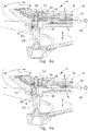
- Fig. 2a shows a setting with enabled relative movement B.
- control arrangement 30 is arranged outside the movement path of the tappet 26 in the region of a lateral edge of the tappet receptacle 28.
- the free path W of the tappet 26 within the tappet receptacle 28 thus has a maximum length.
- the relative movement B can be carried out unhindered. Only at; only when When the backrest 20 or seat 18 reaches a maximum deflection, the tappet 26 strikes an upper wall 36 of the tappet receptacle 28.
- a buffer element 38 is formed on the ram end 37 of the ram 26.
- the buffer element 38 consists of an elastic material, in particular a rubber-elastic material. It is designed as an elastomer spring.
- FIG. 2b shows a setting with a blocked relative movement B. It can be seen that in this setting, by actuating the operating element 34, the control arrangement 30 is displaced into the tappet receptacle 28 and is thus at least partially immersed in it. As a result, the plunger 26 already strikes with the buffer element 38 in the position shown in FIG Figures 2a and 2b The starting position shown here of the relative movement B against the control arrangement 30. The plunger 26 is thus fixed relative to the seat 18. In other words, there is no free path W of the tappet in the tappet receptacle 28 (in Figure 2b therefore not shown).
- the spring element 22 is thus fixed in its starting position.
- the relative movement B cannot be started and therefore cannot be carried out.
- the control arrangement 30 is thus shifted into a blocking position in which the relative movement B is blocked.
- Figures 3a and 3b show according to section A of Fig. 1 another embodiment of the invention.
- this embodiment there is the possibility of choosing different settings so that the relative movement B can be carried out in different degrees in a stepped manner.
- control arrangement 30 which is also formed here from DD11, is not displaceable, but rather is mounted on the edge of the plunger receptacle 28 so as to be rotatable about an axis of rotation D parallel to the longitudinal direction L. It partially protrudes into the plunger receptacle.
- control arrangement 30 a total of four areas 40, 42, 44, 46 of different length or height has.
- a recess is formed on the control arrangement 30 in the region 40.
- the region 40 has a negligibly short length.
- the area 46 has the longest length of the areas 40, 42, 44 and 46.
- control arrangement 30 has an essentially spiral staircase shape with steps pointing downwards in the installed state.
- control arrangement 30 If the control arrangement 30 is thus rotated around its longitudinal axis or around the axis of rotation D by means of the Bowden cable 32 and the operating element 34, a different one of the areas 40, 42, 44, 46 is aligned with the tappet seat 28 or protrudes into the tappet seat 28 .
- the control arrangement 30 can at least partially dip into the plunger receptacle 28, in particular with one of its areas 42, 44 or 46.
- Figures 3a and 3b for this purpose, two different settings with correspondingly different positions, in particular rotational positions, of the control arrangement 30.
- the free path W of the plunger 26 together with the buffer element 38 can be adjusted. So is according to the attitude Fig. 3a the free path W is much shorter than with the setting according to Figure 3b .
- the relative movement B is limited to a lesser extent than in the last-mentioned setting.
- control arrangement 30 If the control arrangement 30 is brought into a rotational position in which the area 40 is oriented towards the tappet receptacle 28, the tappet 26 can slide past the control arrangement 30; the free path W reaches its maximum possible length; the extent of the relative movement B is not limited by the control arrangement 30.
- Figures 4a and 4b refer to. In the embodiment shown there, an even finer gradation of the limitation settings can be achieved compared to the embodiment described above.
- control arrangement 30 is constructed in several parts. It can at least partially dip into the plunger receptacle 28 from above, in particular protrude into it.
- the control arrangement 30 is formed by a locking part 48 and by a limiting part 50 .
- the locking part 48 is in turn actuated by a Bowden cable 32 and an operating element 34.
- the delimitation part 50 has a latching surface 51 with a plurality of grooves 52 which together form a toothed rack.
- the locking part 48 is essentially plate-shaped and is mounted displaceably transversely to the delimitation part 50. In the longitudinal direction of the delimitation part 50 and thus also parallel to the longitudinal direction L of the plunger receptacle 28, the locking part 48 is, however, fixed on the seat 18. The thickness of the locking part 48 is matched to the width of the grooves 52. Thus, the locking part 48 can be pushed into one of the grooves 52 and thereby fix the delimiting part 50 along the longitudinal direction L at different heights, in particular lock it. The fixing or latching can be released by corresponding opposite actuation of the actuating element 34 or by opposite movement of the Bowden cable 32.
- the limiting part 50 is designed as a counter-ram. It can be seen that with the setting according to Figure 4a the limiting part 50 is located in its lowest height position and thus already in the starting position of the relative movement B shown there abuts against the plunger 26 and its buffer element 38 and thus blocks its movement. The plunger 26 thus has no free path W (in Figure 4a therefore cannot be shown) in the plunger receptacle 28. Thus, with this setting, the relative movement B is also blocked.
- the limiting part 50 When setting according to Figure 4b on the other hand, the limiting part 50 is at its highest possible altitude.
- the free path W of the plunger 26 thus has its maximum length; the relative movement B can thus again be carried out unhindered up to its maximum deflection with this setting.
- the procedure can be as follows.
- the locking part 48 is actuated by means of the operating element 34 and the Bowden cable 32 in order to release the delimiting part 50.
- the limiting part 50 thus moves into the low altitude position according to FIG Figure 4a .
- the plunger 26 moves upwards. As a result, it takes the delimitation part 50 with it and thus changes its altitude.
- the locking part 48 can in turn be actuated in order to fix the delimiting part 50 in the longitudinal direction L at this height position.
- the relative movement B is thus set to a desired (possibly medium) extent.
- FIG Figures 5a and 5b Another embodiment of the invention is shown in FIG Figures 5a and 5b shown. This embodiment enables a stepless adjustment of the extent of the relative movement B.
- Figure 5c shows the control arrangement 30 used in this embodiment in a perspective illustration. It can be seen that in this embodiment too, the control arrangement 30 has a limiting part 50 and a locking part 48.
- the delimitation part 50 is, however, essentially smooth on the outside and has a cylindrical and, in particular, rod-shaped overall shape.
- the locking part 48 is made up of two components, in particular a clamping clasp 54 (see also the perspective illustration of the clamping clasp 54 in FIG Fig. 5d ) and a clamping plate 56 (see also the perspective view of the clamping plate 56 in Figure 5e ) educated.
- a clamping spring 55 can optionally also be arranged between the clamping clasp 54 and the clamping plate 56.
- the clamping clasp 54 and the clamping plate 56 each have a recess 58 .
- the recesses 58 are arranged in alignment with one another, so that the delimitation part 50 can be arranged in the recesses 58.
- the limiting part 50 can thus be frictionally fixed on the locking part 48 by clamping.
- the locking part 48 thus forms a clamping element. If in the assembled state of the locking part 48, the limiting part 50 from below, for. B. by pushing the plunger 26 ( Figures 5a and 5b ), loaded, the clamping is automatically initiated or reinforced.
- the locking part is designed and arranged to be self-locking. This self-clamping can be additionally supported by the clamping spring 55.
- the delimitation part 50 can again at least partially dip from above into the plunger receptacle 28, in particular protrude into it.
- the altitude can again be adjusted of the limiting part 50 - here, however, steplessly - can be set.
- the extent of the relative movement B can thus be continuously adjusted.
- Fig. 2a or 2b 3a or 3b, 4a or 4b and 5a or 5b is the respective tappet 26 with its tappet end 37 ( Fig. 2a or Fig. 2b ) opposite end movable in column connection part 24 ( Fig. 1 ) movably mounted.
- FIG. 2a that at the upper end of the support connection part 24 the plunger 26 is mounted in a receiving plate 60 in connection with a hemispherical screw connection 62.
- the seat 18 can thus be tilted forwards, backwards and / or laterally relative to the spring element 22.
- Fig. 2a it can be seen that the tappet 26, which plunges into the tappet receptacle 28 during the relative movement B, forms a guide for the seat 18.
Landscapes
- Health & Medical Sciences (AREA)
- Dentistry (AREA)
- General Health & Medical Sciences (AREA)
- Seats For Vehicles (AREA)
Description
- Die Erfindung geht aus von einem Sitzmöbel
- mit einem eine Stütze aufweisenden Fußgestell,
- mit einer Sitzanordnung,
- wobei die Sitzanordnung über ein Federelement mit einem Stützenverbindungsteil, das sich an der Stütze abstützt, verbunden ist, und wobei die Sitzanordnung gegen die Rückstellkraft des Federelements in einer Relativbewegung relativ zu dem Stützenverbindungsteil bewegbar ist, und
- mit einem im Bereich zwischen dem Stützenverbindungsteil und der Sitzanordnung angeordneten Stößel, der bei Annäherung der Sitzanordnung an das Stützenverbindungsteil in eine Stößelaufnahme entlang einer Längsrichtung der Stößelaufnahme eintaucht.
- Ein solches Sitzmöbel ist beispielsweise aus der
DE 10 2016 102 557 A1 bekannt. - Das Sitzmöbel, beispielsweise ein Bürostuhl, weist üblicherweise eine Sitzanordnung mit einem Sitz und einer Rückenlehne auf.
- Die Sitzanordnung lässt sich relativ zum Stützenverbindungsteil und damit relativ zum Fußgestell abgefedert durch das Federelement bzw. dessen Rückstellkraft bewegen.
- Ergonomisch ist es wünschenswert, diese Relativbewegung steuern zu können. Insbesondere ist es wünschenswert, dass ein Benutzer des Sitzmöbels die Relativbewegung nach seinen Wünschen begrenzen und/oder blockieren kann. Mit anderen Worten sollten eine oder mehrere Bewegungsmöglichkeiten des Sitzmöbels steuerbar, insbesondere in ihrem Ausmaß begrenzbar und/oder blockierbar, sein.
- Eine solche Steuerung der Relativbewegung sollte dazu besonders flexibel sein und möglichst umfassende Einstellmöglichkeiten bieten. Die Steuerung sollte zudem möglichst einfach in unterschiedliche Modelle von Sitzmöbeln integrierbar sein.
- Aufgabe der Erfindung ist es daher, ein Sitzmöbel anzubieten, bei dem die Relativbewegung der Sitzanordnung relativ zum Stützenverbindungsteil flexibel steuerbar ist.
- Gelöst wird die Aufgabe durch ein Sitzmöbel
- mit einem eine Stütze aufweisenden Fußgestell,
- mit einer Sitzanordnung,
- wobei die Sitzanordnung über ein Federelement mit einem Stützenverbindungsteil, das sich an der Stütze abstützt, verbunden ist, und wobei die Sitzanordnung gegen die Rückstellkraft des Federelements in einer Relativbewegung relativ zu dem Stützenverbindungsteil bewegbar ist, und
- mit einem im Bereich zwischen dem Stützenverbindungsteil und der Sitzanordnung angeordneten Stößel, der bei Annäherung der Sitzanordnung an das Stützenverbindungsteil in eine Stößelaufnahme entlang einer Längsrichtung der Stößelaufnahme eintaucht,
- wobei das Sitzmöbel eine Steueranordnung zur Steuerung, insbesondere zur Blockade und/oder zur Begrenzung, der Relativbewegung aufweist, wobei die Steueranordnung zur Steuerung wenigstens teilweise in die Stößelaufnahme eintauchen kann und/oder durch die die Stößelaufnahme zumindest bereichsweise entlang ihrer Längsrichtung verkürzbar und/oder verlängerbar ist.
- Dabei kann unter "eintauchen" verstanden werden, dass der Stößel bzw. die Steueranordnung in die Stößelaufnahme eindringt und/oder dass sich der Stößel bzw. die Steueranordnung innerhalb der Stößelaufnahme verlagert.
- Die Stößelaufnahme kann ebenfalls im Bereich zwischen dem Stützenverbindungsteil und der Sitzanordnung angeordnet sein. Bevorzugt weist sie einen Hohlraum auf, der wenigstens an derjenigen Seite eine Öffnung aufweist, an der bzw. durch die der Stößel in die Stößelaufnahme hineingelangt. Die Stößelaufnahme kann eine längliche Form aufweisen.
- Unter Längsrichtung der Stößelaufnahme kann die Richtung verstanden werden, die vorgesehen ist, um den Stößel in die Stößelaufnahme aufzunehmen bzw. um den Stößel in der Stößelaufnahme zu bewegen. Bevorzugt kann die Längsrichtung der Richtung eines längsten Durchmessers der Stößelaufnahme entsprechen.
- Bei einem solchen Sitzmöbel bewegt sich somit während der Relativbewegung der Stößel in die Stößelaufnahme hinein und/oder der Stößel bewegt sich innerhalb der Stößelaufnahme. Durch die Steueranordnung kann der freie Weg des Stößels, insbesondere entlang der Längsrichtung, innerhalb der Stößelaufnahme vorab eingestellt werden.
- Unter "freier Weg innerhalb der Stößelaufnahme" kann dabei die Strecke bzw. der Weg verstanden werden, die der Stößel, ausgehend von einer Ausgangsstellung des Stößels bei unbelasteter Sitzanordnung bzw. vor Beginn der Relativbewegung, während der Relativbewegung zurücklegen kann ohne gegen eine gegenüberliegende Wand der Stößelaufnahme oder gegen ein anderes Objekt zu stoßen, insbesondere ohne gegen die Steueranordnung zu stoßen.
- Somit kann die Relativbewegung begrenzt werden. Der Stößel kann dazu mit der Steueranordnung zur Begrenzung der Relativbewegung zusammenwirken. Insbesondere kann der Stößel in einer Endstellung einer begrenzten Relativbewegung an die Steueranordnung anstoßen.
- Wird der freie Weg des Stößels vollständig durch die Steueranordnung verkürzt, lässt sich eine Blockade der Relativbewegung erreichen.
- Je nach Ausgestaltung des Sitzmöbels lässt sich damit auch einstellen, inwieweit beispielsweise eine Rückenlehne des Sitzmöbels relativ zu einem Sitz und/oder relativ zum Fußgestell bewegbar ist.
- Zur Begrenzung der Relativbewegung auf einen Maximalausschlag kann ein Anschlag, an den der Stößel bei Erreichen einer Endstellung der Relativbewegung anstößt, insbesondere an der Sitzanordnung, ausgebildet sein. Alternativ und/oder ergänzend kann der Stößel bei Erreichen der Endstellung auch unmittelbar an der Sitzanordnung anstoßen.
- Der Stößel kann eine Führung für die Sitzanordnung, insbesondere während der Relativbewegung, bilden. Dazu kann er mit der Sitzanordnung zusammenwirken.
- Die Steueranordnung kann auch nachträglich in das Sitzmöbel integriert werden. Die Steueranordnung selbst kann in vielfältiger Weise ausgebildet, insbesondere geformt, sein. Somit lässt sich die Steuerung der Relativbewegung bei unterschiedlichen Modellen von Sitzmöbeln verwenden. Die Art der Steuerung und der Umfang der hieraus resultierenden Einstellmöglichkeiten lassen sich, insbesondere durch Einsatz unterschiedlicher Steueranordnungen, je nach gewünschtem Anwendungsbereich des Sitzmöbels anpassen.
- Vorteilhaft ist es, wenn der Stößel an seinem Stößelende ein Pufferelement aufweist. Das Pufferelement kann insbesondere als Elastomerfeder ausgebildet sein oder eine solche aufweisen. Somit kann der Stoß des Stößels und damit die Relativbewegung, insbesondere bei Erreichen einer jeweiligen Endstellung, zusätzlich gedämpft bzw. abgefedert werden.
- Die Lage und/oder die Position der Steueranordnung können mittels eines Bedienelements, insbesondere über einen Bowdenzug, einstellbar sein. Unter Lage und/oder Position der Steueranordnung kann dazu ihre jeweilige relative Lage und/oder relative Position in Bezug auf die Lage und/oder Position der Sitzanordnung und/oder in Bezug auf die Lage und/oder Position des Stützenverbindungsteils in einer Anfangsstellung vor Beginn der Relativbewegung verstanden werden.
- Bei einer Klasse von Ausführungsformen der Erfindung ist es vorgesehen, dass die Steueranordnung in eine Blockadeposition verschiebbar ist, in der die Relativbewegung begrenzt, insbesondere blockiert, ist. Insbesondere kann vorgesehen sein, dass die Steueranordnung wenigstens teilweise, bevorzugt vollständig, zur Begrenzung der Relativbewegung in die Stößelaufnahme hinein und zur Freigabe der Relativbewegung aus der Stößelaufnahme heraus verschoben wird. Dann kann die Steueranordnung als Rastschieber, insbesondere als Blockierschieber, wirken.
- Alternativ oder ergänzend kann die Steueranordnung um eine, bevorzugt zur Längsrichtung parallele, Drehachse drehbar gelagert sein. Besonders bevorzugt kann die Steueranordnung wenigstens zwei Bereiche mit unterschiedlicher Länge parallel zur Längsrichtung aufweisen. Dann kann der freie Weg des Stößels durch Drehung der Steueranordnung oder eines Teils der Steueranordnung eingestellt werden.
- Die Steueranordnung kann ein Begrenzungsteil zur Begrenzung des freien Weges des Stößels in der Stößelaufnahme sowie ein Arretierteil zur Festlegung der Lage und/oder der Position des Begrenzungsteils aufweisen. Mittels des Arretierteils kann dann die Lage und/oder die Position des Begrenzungsteils eingestellt und festgelegt werden. Beispielsweise kann das Begrenzungsteil weiter in die Stößelaufnahme hinein oder aus der Stößelaufnahme heraus verlagert werden und in der neuen Position festgelegt werden. Somit lässt sich der freie Weg mittels des Arretierteils und des Begrenzungsteils einstellen. Auch somit kann die Relativbewegung einstellbar begrenzt und/oder blockiert werden.
- Dazu kann die Steueranordnung, insbesondere das Begrenzungsteil, als entlang der Längsrichtung verlagerbarer Gegenstößel ausgebildet sein und/oder einen solchen aufweisen. Insbesondere kann vorgesehen sein, dass bei Erreichen einer jeweiligen Endstellung der Relativbewegung der Stößel mit seinem Stößelende an das als Gegenstößel ausgebildete Begrenzungsteil anstößt. Auch hierbei kann der Stoß durch das am Stößelende angeordnete Pufferelement gedämpft werden.
- Das Begrenzungsteil kann, insbesondere wenn es als Gegenstößel ausgebildet ist und/oder einen solchen aufweist, wenigstens eine Rastfläche aufweisen. Die Rastfläche kann insbesondere als Rastnut, Kerbe und/oder als Keil ausgebildet sein. Das Arretierteil kann dann wenigstens bereichsweise komplementär zur Rastfläche ausgebildet sein. Somit kann das Arretierteil zur Festlegung, insbesondere zur Verrastung, des Begrenzungsteils in die Rastfläche eingreifen. Allgemein kann ein Formschluss zwischen dem Arretierteil und dem Begrenzungsteil, insbesondere im Bereich der Rastfläche, hergestellt werden. Dabei ist denkbar, dass die Steueranordnung mehrere Rastnuten aufweist. Beispielsweise kann die Steueranordnung als Zahnstange ausgebildet sein und/oder einen zahnstangenförmigen Bereich aufweisen. Dann kann das Begrenzungsteil in unterschiedlichen Positionen und/oder Lagen festgelegt, insbesondere verrastet, werden.
- Eine stufenlose Steuerung der Relativbewegung lässt sich erzielen, wenn das Arretierteil als Klemmelement, durch das das Begrenzungsteil durch Reibschluss in seiner Lage und/oder seiner Position relativ zur Sitzanordnung lösbar festlegbar ist, ausgebildet ist oder ein solches aufweist. Insbesondere kann das Arretierteil eingerichtet sein, das Begrenzungsteil in seiner Lage und/oder seiner Position lösbar festzuklemmen und damit lösbar festzulegen. Unter "lösbar" kann dabei die Möglichkeit verstanden werden, die Klemmung, insbesondere reversibel, zu lockern und/oder aufzuheben.
- Dann kann der freie Weg des Stößels in der Stößelaufnahme und dadurch die Endstellung der Relativbewegung stufenlos eingestellt bzw. festgelegt werden, indem zunächst die Klemmung durch das Arretierteil, beispielsweise mittels des Bedienelements und/oder mittels des Bowdenzugs, gelöst wird, der Gegenstößel bei unbelasteter Sitzanordnung sodann - beispielsweise schwerkraftgetrieben - bis zum Stößel bewegt wird, anschließend die Relativbewegung manuell bis zum Erreichen der gewünschten Endstellung ausgeführt wird bzw. die Sitzanordnung, insbesondere die Rückenlehne, entsprechend belastet wird und abschließend die Klemmung durch das Arretierteil wieder hergestellt wird.
- Vorzugsweise kann das Arretierteil selbstklemmend ausgebildet und/oder angeordnet sein. Mit anderen Worten kann das Arretierteil eingerichtet sein, bei Belastung des Begrenzungsteils, insbesondere wenn der Stößel gegen das Begrenzungsteil stößt, die Klemmung des Begrenzungsteils zu initiieren und/oder zu verstärken.
- Alternativ oder ergänzend kann die Steueranordnung eine Klemmfeder zur lösbaren Festlegung des Begrenzungsteils durch das Arretierteil aufweisen. Die Klemmfeder kann insbesondere eine Vorspannung des Arretierteils bewirken, sodass das Begrenzungsteil - insbesondere ohne Betätigen des Bedienelements und/oder ohne Einwirkung des Stößels auf das Begrenzungsteil - klemmend in seiner Lage und/oder Position festgelegt ist. Insbesondere kann die Klemmfeder die Klemmung initiieren und/oder verstärken.
- Die Steueranordnung kann aus einem Metall und/oder aus einem Kunststoff gebildet sein. Insbesondere hat es sich als günstig ergeben, wenn die Steueranordnung aus DD11, insbesondere als Stahlblech, ausgebildet ist oder dieses aufweist.
- Vorzugsweise ist der Stößel, insbesondere mit seinem dem Stößelende gegenüberliegenden Ende, am Stützenverbindungsteil gelagert. Bevorzugt kann er beweglich gelagert sein. Insbesondere kann der Stößel in einem Kalottenlager gelagert sein. So ist denkbar, dass der Stößel in einem Aufnahmeteller in Verbindung mit einer insbesondere halbkugelförmigen Verschraubung gelagert ist. Dann lässt sich der Sitz nach vorne, hinten und/oder seitlich relativ zum Federelement verkippen und/oder verschwenken.
- Die Bewegungsmöglichkeiten des Sitzmöbels können ferner hinsichtlich ergonomischer Aspekte zusätzlich abgestimmt werden, wenn das Federelement als Federpaket ausgebildet ist oder ein solches aufweist. Allgemein kann das Federelement aus wenigstens zwei verschiedenen Materialien gebildet sein. Somit lässt sich die Materialelastizität des Federelements in einem weiten Elastizitätsbereich vordefinieren und/oder einstellen. Das Federelement kann zum Beispiel mehrere Blattfedern aufweisen. Dabei können zumindest eine Blattfeder aus Kunststoff und zumindest eine Blattfeder aus Metall ausgebildet sein. Die Blattfedern können unterschiedliche Dicken aufweisen. Die Blattfedern können abschnittsweise aneinander anliegen.
- Bei einer besonders bevorzugten Klasse von Ausführungsformen der Erfindung ist das Sitzmöbel als Stuhl, insbesondere als Bürodrehstuhl, ausgebildet.
- Weitere Merkmale und Vorteile der Erfindung ergeben sich aus der nachfolgenden detaillierten Beschreibung der Ausführungsbeispiele der Erfindung, anhand der Figuren der Zeichnung, die erfindungswesentliche Einzelheiten zeigt, sowie aus den Ansprüchen.
- Die in der Zeichnung dargestellten Merkmale sind derart dargestellt, dass die erfindungsgemäßen Besonderheiten deutlich sichtbar gemacht werden können. Die verschiedenen Merkmale können je einzeln für sich oder zu mehreren in beliebigen Kombinationen bei Varianten der Erfindung verwirklicht sein.
- Es zeigen:
- Fig. 1
- ein erstes Sitzmöbel in Querschnittsansicht;
- Fig. 2a und 2b
- Detailansichten des Ausschnitts A gemäß der Ausführungsform der
Fig. 1 bei zwei verschiedenen Einstellungen; - Fig. 3a und 3b
- Detailansichten gemäß dem Ausschnitt A der
Fig. 1 einer weiteren Ausführungsform bei zwei verschiedenen Einstellungen; - Fig. 3c
- sechs verschiedene perspektivische Ansichten einer für die Ausführungsform gemäß
Fig.3a und 3b verwendeten Steueranordnung; - Fig. 4a und 4b
- Detailansichten gemäß dem Ausschnitt A der
Fig. 1 einer weiteren Ausführungsform bei zwei verschiedenen Einstellungen; - Fig. 5a und 5b
- Detailansichten gemäß dem Ausschnitt A der
Fig. 1 einer weiteren Ausführungsform bei zwei verschiedenen Einstellungen; - Fig. 5c
- eine perspektivische Ansicht der für die Ausführungsform gemäß
Fig. 5a und Fig. 5b verwendeten Steueranordnung und - Fig. 5d und 5e
- perspektivische Ansichten auf Einzelteile der Steueranordnung gemäß
Fig. 5c . - Zum leichteren Verständnis der Erfindung werden soweit möglich im Folgenden für funktional sich entsprechende Elemente jeweils die gleichen Bezugszeichen verwendet.
-
Fig. 1 zeigt eine erste Ausführungsform eines Sitzmöbels 10 mit einem eine Stütze 12 aufweisenden Fußgestell 14 und mit einer Sitzanordnung 16. Die Sitzanordnung 16 weist einen Sitz 18 sowie eine Rückenlehne 20 auf. - Die Sitzanordnung 16 ist über ein Federelement 22 mit einem Stützenverbindungsteil 24, das sich an der Stütze 12 abstützt, verbunden. Das Federelement 22 ist als Federpaket ausgebildet. Es weist zwei zueinander parallel verlaufende Blattfedern auf. Insgesamt ist das Federelement 22 im Wesentlichen U-förmig geformt.
- Die Sitzanordnung 16, insbesondere ihr Sitz 18 und ihre Rückenlehne 20, ist gegen die Rückstellkraft des Federelements 22 in einer mit den Bezugszeichen B angedeuteten Relativbewegung B relativ zu dem Stützenverbindungsteil 24 bewegbar. Der Verlauf der Relativbewegung B ist im Wesentlichen durch das Federelement 22, insbesondere durch Wahl seiner Elastizität, definiert.
- In einem Bereich zwischen dem Stützenverbindungsteil 24 und der Sitzanordnung 16 ist ein Stößel 26 angeordnet. Der Stößel 26 taucht bei Annäherung der Sitzanordnung 16 an das Stützenverbindungsteil 24 in eine Stößelaufnahme 28 entlang einer Längsrichtung L der Stößelaufnahme 28 ein. Wie
Fig. 1 weiter entnehmbar ist, ist die Stößelaufnahme 28 als Hohlraum unterseitig des Sitzes 18 an diesem ausgebildet. - Wie noch in den folgenden Figuren näher erläutert wird, ist bei dieser Ausführungsform an einer Seite der Stößelaufnahme 28 eine Steueranordnung 30 beweglich angeordnet. Die Steueranordnung 30 kann mittels eines Bowdenzugs 32, der mit einem Bedienelement 34 verbunden ist, betätigt werden. Durch Betätigen der Steueranordnung 30 kann eine Einstellung der Relativbewegung B gewählt werden. Mit anderen Worten kann die Relativbewegung B, insbesondere die maximal mögliche Relativbewegung, gesteuert werden.
- Die Steueranordnung 30 ist aus DD11 gebildet.
- Bei der Ausführungsform der Erfindung gemäß
Fig. 1 besteht die Möglichkeit, die Relativbewegung B entweder vollständig zu blockieren oder diese freizugeben. Dazu kann, wie noch weiter unten näher erläutert wird, die Steueranordnung 30 zur Steuerung, insbesondere zur Blockade, der Relativbewegung, in die Stößelaufnahme 28 eintauchen. Zur Freigabe der Relativbewegung kann die Steueranordnung 30 aus der Stößelaufnahme 30 heraus verschoben werden. - Zur näheren Erläuterung der Funktionsweise dieser Ausführungsform zeigen
Fig. 2a und Fig. 2b Detailansichten des Ausschnitts A derFig. 1 . -
Fig. 2a zeigt dabei eine Einstellung mit freigegebener Relativbewegung B. - Zu erkennen ist, dass die Steueranordnung 30 außerhalb der Bewegungsbahn des Stößels 26 im Bereich eines seitlichen Randes der Stößelaufnahme 28 angeordnet ist. Somit weist der freie Weg W des Stößels 26 innerhalb der Stößelaufnahme 28 eine maximale Länge auf. Die Relativbewegung B kann ungehindert ausgeführt werden. Erst bei Erreichen einer Maximalauslenkung der Rückenlehne 20 bzw. des Sitzes 18 stößt der Stößel 26 an eine obere Wand 36 der Stößelaufnahme 28.
- Am Stößelende 37 des Stößels 26 ist ein Pufferelement 38 ausgebildet. Das Pufferelement 38 besteht aus einem elastischen Material, insbesondere aus einem gummielastischen Material. Es ist als Elastomerfeder ausgebildet. Somit sind Stöße des Stößels 26 gegen die obere Wand 36 - oder wie im Folgenden noch beschrieben gegen die Steueranordnung 30 - gedämpft.
-
Fig. 2b zeigt eine Einstellung mit blockierter Relativbewegung B. Zu erkennen ist, dass bei dieser Einstellung durch Betätigen des Bedienelements 34 die Steueranordnung 30 in die Stößelaufnahme 28 hinein verschoben ist und damit in diese zumindest teilweise eingetaucht ist. Dadurch stößt der Stößel 26 mit dem Pufferelement 38 bereits in der inFig. 2a und Fig. 2b gezeigten Ausgangsstellung der Relativbewegung B gegen die Steueranordnung 30. Der Stößel 26 ist somit relativ zum Sitz 18 festgelegt. Mit anderen Worten besteht keine freie Weglänge W des Stößels in der Stößelaufnahme 28 (inFig. 2b daher nicht eingezeichnet). - Das Federelement 22 ist somit in seiner Ausgangsstellung fixiert. Die Relativbewegung B kann nicht begonnen und damit auch nicht ausgeführt werden. Die Steueranordnung 30 ist somit in eine Blockadeposition verschoben, in der die Relativbewegung B blockiert ist.
-
Fig. 3a und Fig. 3b zeigen entsprechend dem Ausschnitt A derFig. 1 eine weitere Ausführungsform der Erfindung. Bei dieser Ausführungsform besteht die Möglichkeit, unterschiedliche Einstellungen zu wählen, sodass die Relativbewegung B abgestuft in unterschiedlichem Ausmaß ausgeführt werden kann. - Dazu ist bei dieser Ausführungsform die Steueranordnung 30, die auch hier aus DD11 gebildet ist, nicht verschiebbar, sondern um eine zur Längsrichtung L parallele Drehachse D am Rand der Stößelaufnahme 28 drehbar gelagert. Teilweise ragt sie in die Stößelaufnahme hinein.
- Anhand
Fig. 3c , die sechs verschiedene perspektivische Ansichten auf die Steueranordnung 30 dieser Ausführungsform zeigt, ist zu erkennen, dass die Steueranordnung 30 insgesamt vier Bereiche 40, 42, 44, 46 unterschiedlicher Länge bzw. Höhe aufweist. Im Bereich 40 ist dazu an der Steueranordnung 30 eine Ausnehmung ausgebildet. Mit anderen Worten weist der Bereich 40 eine verschwindend geringe Länge auf. Dahingegen weist der Bereich 46 die längste Länge der Bereiche 40, 42, 44 und 46 auf. - Insgesamt weist die Steueranordnung 30 eine im Wesentlichen spindeltreppenförmige Gestalt mit im Einbauzustand nach unten gerichteten Stufen auf.
- Wird somit die Steueranordnung 30 mittels des Bowdenzugs 32 und des Bedienelements 34 um seine Längsachse bzw. um die Drehachse D gedreht, ist jeweils ein anderer der Bereiche 40, 42, 44, 46 zur Stößelaufnahme 28 hin ausgerichtet bzw. ragt in die Stößelaufnahme 28 hinein. Somit kann durch Drehen der Steueranordnung 30 diese zumindest teilweise, insbesondere mit einer ihrer Bereiche 42, 44 oder 46, in die Stößelaufnahme 28 eintauchen. Beispielhaft zeigen
Fig. 3a und Fig. 3b hierzu zwei verschiedene Einstellungen mit entsprechend unterschiedlichen Lagen, insbesondere Drehlagen, der Steueranordnung 30. - Somit lässt sich durch Drehen der Steueranordnung 30 der freie Weg W des Stößels 26 mitsamt dem Pufferelement 38 einstellen. So ist in der Einstellung gemäß
Fig. 3a der freie Weg W wesentlich kürzer als bei der Einstellung gemäßFig. 3b . Somit ist in der erstgenannten Einstellung der Steueranordnung 30 die Relativbewegung B auf ein geringeres Ausmaß begrenzt als bei der letztgenannten Einstellung. - Wird die Steueranordnung 30 in eine Drehlage gebracht, in der der Bereich 40 zur Stößelaufnahme 28 hin ausgerichtet ist, kann der Stößel 26 an der Steueranordnung 30 vorbeigleiten; der freie Weg W erreicht seine maximal mögliche Länge; das Ausmaß der Relativbewegung B ist nicht durch die Steueranordnung 30 begrenzt.
- Eine weitere Ausführungsform der Erfindung ist
Fig. 4a und Fig. 4b zu entnehmen. Bei der dort dargestellten Ausführungsform kann eine noch feinere Abstufung der Begrenzungseinstellungen im Vergleich zur vorangehend beschriebenen Ausführungsform erreicht werden. - Zu erkennen ist zunächst, dass die Steueranordnung 30 mehrteilig ausgebildet ist. Sie kann von oben in die Stößelaufnahme 28 zumindest teilweise eintauchen, insbesondere in diese hineinragen.
- Die Steueranordnung 30 ist durch ein Arretierteil 48 und durch ein Begrenzungsteil 50 gebildet. Das Arretierteil 48 wird dabei wiederum durch einen Bowdenzug 32 und ein Bedienelement 34 betätigt.
- Das Begrenzungsteil 50 weist eine Rastfläche 51 mit mehreren Nuten 52 auf, die insgesamt eine Zahnstange bilden. Das Arretierteil 48 ist im Wesentlichen plattenförmig geformt und quer zum Begrenzungsteil 50 verschiebbar gelagert. In Längsrichtung des Begrenzungsteils 50 und damit auch parallel zur Längsrichtung L der Stößelaufnahme 28 ist das Arretierteil 48 jedoch am Sitz 18 festgelegt. Die Dicke des Arretierteils 48 ist auf die Breite der Nuten 52 abgestimmt. Somit kann das Arretierteil 48 in eine der Nuten 52 eingeschoben werden und dadurch das Begrenzungsteil 50 entlang der Längsrichtung L in unterschiedlichen Höhenlagen festlegen, insbesondere verrasten. Durch entsprechende entgegengesetzte Betätigung des Betätigungselements 34 bzw. durch entgegengesetzte Bewegung des Bowdenzugs 32 ist die Festlegung bzw. Verrastung lösbar.
- Das Begrenzungsteil 50 ist als Gegenstößel ausgebildet. Zu erkennen ist, dass bei der Einstellung gemäß
Fig. 4a das Begrenzungsteil 50 sich in seiner tiefsten Höhenlage befindet und damit bereits in der dort gezeigten Ausgangsstellung der Relativbewegung B gegen den Stößel 26 und dessen Pufferelement 38 stößt und damit dessen Bewegung blockiert. Der Stößel 26 weist somit keinen freien Weg W (inFig. 4a daher nicht darstellbar) in der Stößelaufnahme 28 auf. Somit ist bei dieser Einstellung die Relativbewegung B ebenfalls blockiert. - Bei der Einstellung gemäß
Fig. 4b dagegen befindet sich das Begrenzungsteil 50 in seiner höchstmöglichen Höhenlage. Der freie Weg W des Stößels 26 weist damit seine Maximallänge auf; die Relativbewegung B kann somit bei dieser Einstellung wiederum ungehindert bis zu ihrer Maximalauslenkung ausgeführt werden. - Um nun bei dieser Ausführungsform eine mittlere Höhenlage des Begrenzungsteils 50 einzustellen und somit die Relativbewegung B auf ein mittleres Ausmaß einzustellen, kann wie folgt vorgegangen werden.
- Zunächst wird bei unbelasteter Sitzanordnung 16 mittels des Bedienelements 34 und des Bowdenzugs 32 das Arretierteil 48 betätigt, um das Begrenzungsteil 50 freizugeben. Schwerkraftgetrieben bewegt sich somit das Begrenzungsteil 50 in die tiefe Höhenlage gemäß
Fig. 4a . - Wird nun die Sitzanordnung 16 belastet, d. h. wird die Relativbewegung B nun initiiert, bewegt sich der Stößel 26 nach oben. Er nimmt dadurch das Begrenzungsteil 50 mit und ändert somit dessen Höhenlage. Bei Erreichen einer gewünschten Höhenlage des Begrenzungsteils 50 kann dann wiederum das Arretierteil 48 betätigt werden, um das Begrenzungsteil 50 in dieser Höhenlage in Längsrichtung L festzulegen. Somit ist die Relativbewegung B auf ein gewünschtes (ggf. mittleres) Ausmaß eingestellt.
- Eine weitere Ausführungsform der Erfindung ist in
Fig. 5a und Fig. 5b dargestellt. Diese Ausführungsform ermöglicht eine stufenlose Einstellung des Ausmaßes der Relativbewegung B. -
Fig. 5c zeigt hierzu die bei dieser Ausführungsform verwendete Steueranordnung 30 in einer perspektivischen Darstellung. Zu erkennen ist, dass auch bei dieser Ausführungsform die Steueranordnung 30 ein Begrenzungsteil 50 sowie ein Arretierteil 48 aufweist. Das Begrenzungsteil 50 ist jedoch außenseitig im Wesentlichen glatt und weist eine zylindrische und insbesondere stangenförmige Gesamtform auf. - Das Arretierteil 48 ist dagegen aus zwei Bauteilen, insbesondere einer Klemmspange 54 (siehe auch die perspektivische Darstellung der Klemmspange 54 in
Fig. 5d ) und einer Klemmplatte 56 (siehe auch die perspektivische Darstellung der Klemmplatte 56 inFig. 5e ) gebildet. Zwischen der Klemmspange 54 und der Klemmplatte 56 kann optional auch eine Klemmfeder 55 angeordnet sein. - Die Klemmspange 54 und die Klemmplatte 56 weisen jeweils eine Ausnehmung 58 auf. Die Ausnehmungen 58 sind in montiertem Zustand des Arretierteils 48 zueinander fluchtend angeordnet, sodass das Begrenzungsteil 50 in den Ausnehmungen 58 anordenbar ist. Durch Verschwenken der Klemmspange 54 relativ zur Klemmplatte 56 entlang einer Verschwenkungsbahn V (
Fig. 5c ) lässt sich somit das Begrenzungsteil 50 am Arretierteil 48 durch Verklemmen reibschlüssig festlegen. Das Arretierteil 48 bildet somit ein Klemmelement. Wird dabei in montiertem Zustand des Arretierteils 48 das Begrenzungsteil 50 von unten, z. B. durch Stoß des Stößels 26 (Fig. 5a und Fig. 5b ), belastet, wird die Klemmung selbsttätig initiiert bzw. verstärkt. Mit anderen Worten ist das Arretierteil selbstklemmend ausgebildet und angeordnet. Durch die Klemmfeder 55 lässt sich diese Selbstklemmung zusätzlich unterstützen. - Wie den
Fig. 5a und Fig. 5b entnehmbar ist, kann das Begrenzungsteil 50 wiederum von oben in die Stößelaufnahme 28 zumindest teilweise eintauchen, insbesondere in diese hineinragen. - Analog zu dem Vorgehen zur Einstellung der Relativbewegung B bei der vorangehend geschilderten Ausführungsform kann auch bei dieser Ausführungsform unter Ausnutzung der Schwerkraft und durch Lösen bzw. erneutem Verklemmen des Begrenzungsteils 50 durch Betätigen des Arretierteil 48 mittels des Bowdenzugs 32 bzw. des Betätigungselements 34 wiederum die Höhenlage des Begrenzungsteils 50 - hier jedoch stufenlos - eingestellt werden. Somit lässt sich bei dieser Ausführungsform das Ausmaß der Relativbewegung B stufenlos einstellen.
- Bei allen Ausführungsformen der Erfindung gemäß der
Fig. 2a bzw. 2b, 3a bzw. 3b, 4a bzw. 4b und 5a bzw. 5b ist der jeweilige Stößel 26 mit seinem dem Stößelende 37 (Fig. 2a oder Fig. 2b ) gegenüberliegenden Ende beweglich im Stützenverbindungsteil 24 (Fig. 1 ) beweglich gelagert. - Stellvertretend für die anderen Ausführungsformen wird diese Lagerung anhand von
Fig. 2a näher erläutert. - Dazu zeigt
Fig. 2a , dass am oberen Ende des Stützenverbindungsteils 24 der Stößel 26 in einem Aufnahmeteller 60 in Verbindung mit einer halbkugelförmigen Verschraubung 62 gelagert ist. Somit lässt sich der Sitz 18 nach vorne, nach hinten und/oder seitlich relativ zum Federelement 22 verkippen. - Des Weiteren ist
Fig. 2a zu entnehmen, dass der während der Relativbewegung B in der Stößelaufnahme 28 eintauchende Stößel 26 eine Führung für den Sitz 18 bildet. -
- 10
- Sitzmöbel
- 12
- Stütze
- 14
- Fußgestell
- 16
- Sitzanordnung
- 18
- Sitz
- 20
- Rückenlehne
- 22
- Federelement
- 24
- Stützenverbindungsteil
- 26
- Stößel
- 28
- Stößelaufnahme
- 30
- Steueranordnung
- 32
- Bowdenzug
- 34
- Bedienelement
- 36
- Wand
- 37
- Stößelende
- 38
- Pufferelement
- 40, 42, 44, 46
- Bereich
- 48
- Arretierteil
- 50
- Begrenzungsteil
- 51
- Rastfläche
- 52
- Nuten
- 54
- Klemmspange
- 55
- Klemmfeder
- 56
- Klemmplatte
- 58
- Ausnehmung
- 60
- Aufnahmeteller
- 62
- Verschraubung
- B
- Relativbewegung
- D
- Drehachse
- L
- Längsrichtung
- V
- Verschwenkungsbahn
Claims (15)
- Sitzmöbel (10)- mit einem eine Stütze (12) aufweisenden Fußgestell (14),- mit einer Sitzanordnung (16),- wobei die Sitzanordnung (16) über ein Federelement (22) mit einem Stützenverbindungsteil (24), das sich an der Stütze (12) abstützt, verbunden ist, und wobei die Sitzanordnung (16) gegen die Rückstellkraft des Federelements (22) in einer Relativbewegung (B) relativ zu dem Stützenverbindungsteil (24) bewegbar ist, und- mit einem im Bereich zwischen dem Stützenverbindungsteil (24) und der Sitzanordnung (16) angeordneten Stößel (26), der bei Annäherung der Sitzanordnung (16) an das Stützenverbindungsteil (24) in eine Stößelaufnahme (28) entlang einer Längsrichtung (L) der Stößelaufnahme (28) eintaucht,
dadurch gekennzeichnet,
dass das Sitzmöbel (10) eine Steueranordnung (30) zur Steuerung, insbesondere zur Blockade und/oder zur Begrenzung, der Relativbewegung (B) aufweist, wobei die Steueranordnung (30) zur Steuerung wenigstens teilweise in die Stößelaufnahme (28) eintauchen kann und/oder durch die die Stößelaufnahme (28) zumindest bereichsweise entlang ihrer Längsrichtung (L) verkürzbar und/oder verlängerbar ist. - Sitzmöbel nach Anspruch 1, dadurch gekennzeichnet, dass der Stößel (26) an seinem Stößelende (37) ein Pufferelement (38) aufweist.
- Sitzmöbel nach einem der vorhergehenden Ansprüche, dadurch gekennzeichnet, dass die Lage und/oder die Position der Steueranordnung (30), mittels eines Bedienelements (34), insbesondere über einen Bowdenzug (32), einstellbar ist.
- Sitzmöbel nach einem der vorhergehenden Ansprüche, dadurch gekennzeichnet, dass die Steueranordnung (30) in eine Blockadeposition verschiebbar ist, in der die Relativbewegung (B) begrenzt, insbesondere blockiert, ist.
- Sitzmöbel nach einem der vorhergehenden Ansprüche, dadurch gekennzeichnet, dass die Steueranordnung (30) um eine, bevorzugt zur Längsrichtung (L) parallele, Drehachse (D) drehbar gelagert ist, wobei die Steueranordnung (30) besonders bevorzugt wenigstens zwei Bereiche (40, 42, 44, 46) mit unterschiedlicher Länge parallel zur Längsrichtung (L) aufweist.
- Sitzmöbel nach einem der vorhergehenden Ansprüche, dadurch gekennzeichnet, dass die Steueranordnung (30) ein Begrenzungsteil (50) zur Begrenzung des freien Weges (W) des Stößels (26) in der Stößelaufnahme (26) sowie ein Arretierteil (48) zur Festlegung der Lage und/oder der Position des Begrenzungsteils (50) aufweist.
- Sitzmöbel nach einem der vorhergehenden Ansprüche, dadurch gekennzeichnet, dass die Steueranordnung (30), insbesondere das Begrenzungsteil (50), als entlang der Längsrichtung (L) verlagerbarer Gegenstößel ausgebildet ist und/oder einen solchen aufweist.
- Sitzmöbel nach einem der vorhergehenden Ansprüche, dadurch gekennzeichnet, dass das Begrenzungsteil (30) wenigstens eine Rastfläche (51) aufweist.
- Sitzmöbel nach einem der vorhergehenden Ansprüche, dadurch gekennzeichnet, dass das Arretierteil (48) als Klemmelement, durch das das Begrenzungsteil (50) durch Reibschluss in seiner Lage und/oder seiner Position relativ zur Sitzanordnung (16) lösbar festlegbar ist, ausgebildet ist oder ein solches aufweist.
- Sitzmöbel nach einem der vorhergehenden Ansprüche, dadurch gekennzeichnet, dass das Arretierteil (48) selbstklemmend ausgebildet und/oder angeordnet ist.
- Sitzmöbel nach einem der vorhergehenden Ansprüche, dadurch gekennzeichnet, dass die Steueranordnung (30) eine Klemmfeder (55) zur lösbaren Festlegung des Begrenzungsteils (50) durch das Arretierteil (48) aufweist.
- Sitzmöbel nach einem der vorhergehenden Ansprüche, dadurch gekennzeichnet, dass die Steueranordnung aus DD11 ausgebildet ist oder DD11 aufweist.
- Sitzmöbel nach einem der vorhergehenden Ansprüche, dadurch gekennzeichnet, dass der Stößel (26), insbesondere mit seinem dem Stößelende (37) gegenüberliegenden Ende, am Stützenverbindungsteil (24) gelagert ist.
- Sitzmöbel nach einem der vorhergehenden Ansprüche, dadurch gekennzeichnet, dass das Federelement (22) als Federpaket ausgebildet ist oder ein solches aufweist.
- Sitzmöbel nach einem der vorhergehenden Ansprüche, dadurch gekennzeichnet, dass das Sitzmöbel (10) als Stuhl, insbesondere als Bürodrehstuhl, ausgebildet ist.
Priority Applications (1)
| Application Number | Priority Date | Filing Date | Title |
|---|---|---|---|
| PL19198290T PL3636106T3 (pl) | 2018-10-12 | 2019-09-19 | Mebel do siedzenia z ograniczaną i/lub blokowaną możliwością ruchu |
Applications Claiming Priority (1)
| Application Number | Priority Date | Filing Date | Title |
|---|---|---|---|
| DE102018125345.1A DE102018125345A1 (de) | 2018-10-12 | 2018-10-12 | Sitzmöbel mit begrenzbarer und/oder blockierbarer Bewegungsmöglichkeit |
Publications (2)
| Publication Number | Publication Date |
|---|---|
| EP3636106A1 EP3636106A1 (de) | 2020-04-15 |
| EP3636106B1 true EP3636106B1 (de) | 2021-04-14 |
Family
ID=67998103
Family Applications (1)
| Application Number | Title | Priority Date | Filing Date |
|---|---|---|---|
| EP19198290.9A Active EP3636106B1 (de) | 2018-10-12 | 2019-09-19 | Sitzmöbel mit begrenzbarer und/oder blockierbarer bewegungsmöglichkeit |
Country Status (5)
| Country | Link |
|---|---|
| EP (1) | EP3636106B1 (de) |
| DE (1) | DE102018125345A1 (de) |
| DK (1) | DK3636106T3 (de) |
| ES (1) | ES2874478T3 (de) |
| PL (1) | PL3636106T3 (de) |
Family Cites Families (6)
| Publication number | Priority date | Publication date | Assignee | Title |
|---|---|---|---|---|
| FR1287379A (fr) * | 1960-11-28 | 1962-03-16 | Dispositif tournant, réglable en hauteur et basculant suivant le poids de l'utilisateur, pour siège, plus spécialement pour siège de bureau | |
| IT978377B (it) * | 1973-01-23 | 1974-09-20 | Folco Z | Struttura mobile con raggio di curvatura di valore zero |
| DE2525752C2 (de) * | 1975-06-10 | 1984-06-07 | Stabilus Gmbh, 5400 Koblenz | Höhenverstellbarer Stuhl mit Neigungsänderung von Lehne oder Sitzfläche |
| DE3724605C2 (de) * | 1987-07-24 | 1994-02-03 | Inaba Seisakusho Ltd | Sitzmöbel |
| DE29701084U1 (de) * | 1997-01-23 | 1997-05-22 | L. & C. Arnold GmbH, 73614 Schorndorf | Liegemöbel, insbesondere Kranken- oder Pflegebett |
| DE102016102557A1 (de) * | 2016-02-15 | 2017-08-17 | Interstuhl Büromöbel GmbH & Co. KG | Sitzmöbel mit einem Rückneigeanschlag |
-
2018
- 2018-10-12 DE DE102018125345.1A patent/DE102018125345A1/de not_active Withdrawn
-
2019
- 2019-09-19 DK DK19198290.9T patent/DK3636106T3/da active
- 2019-09-19 ES ES19198290T patent/ES2874478T3/es active Active
- 2019-09-19 EP EP19198290.9A patent/EP3636106B1/de active Active
- 2019-09-19 PL PL19198290T patent/PL3636106T3/pl unknown
Non-Patent Citations (1)
| Title |
|---|
| None * |
Also Published As
| Publication number | Publication date |
|---|---|
| DE102018125345A1 (de) | 2020-04-16 |
| ES2874478T3 (es) | 2021-11-05 |
| EP3636106A1 (de) | 2020-04-15 |
| PL3636106T3 (pl) | 2021-09-27 |
| DK3636106T3 (da) | 2021-05-17 |
Similar Documents
| Publication | Publication Date | Title |
|---|---|---|
| EP0079530B1 (de) | Arretierbare Wippvorrichtung für Sitzteile von Sitzmöbeln | |
| DE10116821B4 (de) | Verstellbare Armlehnenanordnung mit einem einzigen Verstellhebel | |
| EP0254808B1 (de) | Höhen- und neigungsverstellbare Kopfstütze mit mittlerem Fenster für Kraftfahrzeugsitze | |
| EP1492702B1 (de) | Kopfstütze für einen sitz | |
| DE19603911C2 (de) | Klappbare Rückenlehne für Fahrzeugsitze, insbesondere Kraftfahrzeugsitze | |
| DE202005005988U1 (de) | Armlehne, insbesondere für einen Bürostuhl | |
| DE102005055337A1 (de) | Federbelastete Kopfstütze | |
| EP3456583B1 (de) | Armlehne | |
| EP0264555A2 (de) | Stuhl, insbesondere Bürostuhl, mit höhenverstellbarer Rückenlehne | |
| EP0198056B1 (de) | Sitzträger für stühle, insbesondere arbeitsdrehstühle | |
| EP3120732B1 (de) | Mechanik für einen bürostuhl | |
| EP3854263A1 (de) | Armlehne, insbesondere für einen bürostuhi | |
| EP2083656B1 (de) | Höhenverstellbare armlehne, insbesondere für einen bürostuhl | |
| EP3636106B1 (de) | Sitzmöbel mit begrenzbarer und/oder blockierbarer bewegungsmöglichkeit | |
| EP2172136B1 (de) | Sitzmöbel mit Sitzteil und Rückenteil | |
| DE2940141C2 (de) | Einrichtung zur Rückenlehnenverstellung | |
| DE19959104A1 (de) | Höhenverstellbare Armlehne für Stühle, insbesondere für Bürostühle | |
| EP0056454A2 (de) | Sitzmöbel, insbesondere drehbarer Bürostuhl | |
| DE2934084C2 (de) | Schreibgerät mit einer Schreibmine | |
| EP4139164B1 (de) | Kopfstütze für einen sitz und fahrzeugsitz | |
| DE202022105640U1 (de) | Mehrteiliger Armlehnenträger | |
| DE202016104850U1 (de) | Vorrichtung zum Erlegen von Insekten | |
| DE102024111315A1 (de) | Hebelarm für einen möbelbeschlag | |
| EP2080450B1 (de) | Höhenverstellbare Armlehne | |
| DE202023101105U1 (de) | Sitzkörper und Stuhl mit einem solchen Sitzkörper |
Legal Events
| Date | Code | Title | Description |
|---|---|---|---|
| PUAI | Public reference made under article 153(3) epc to a published international application that has entered the european phase |
Free format text: ORIGINAL CODE: 0009012 |
|
| STAA | Information on the status of an ep patent application or granted ep patent |
Free format text: STATUS: THE APPLICATION HAS BEEN PUBLISHED |
|
| AK | Designated contracting states |
Kind code of ref document: A1 Designated state(s): AL AT BE BG CH CY CZ DE DK EE ES FI FR GB GR HR HU IE IS IT LI LT LU LV MC MK MT NL NO PL PT RO RS SE SI SK SM TR |
|
| AX | Request for extension of the european patent |
Extension state: BA ME |
|
| STAA | Information on the status of an ep patent application or granted ep patent |
Free format text: STATUS: REQUEST FOR EXAMINATION WAS MADE |
|
| 17P | Request for examination filed |
Effective date: 20200929 |
|
| RBV | Designated contracting states (corrected) |
Designated state(s): AL AT BE BG CH CY CZ DE DK EE ES FI FR GB GR HR HU IE IS IT LI LT LU LV MC MK MT NL NO PL PT RO RS SE SI SK SM TR |
|
| GRAP | Despatch of communication of intention to grant a patent |
Free format text: ORIGINAL CODE: EPIDOSNIGR1 |
|
| STAA | Information on the status of an ep patent application or granted ep patent |
Free format text: STATUS: GRANT OF PATENT IS INTENDED |
|
| INTG | Intention to grant announced |
Effective date: 20201218 |
|
| GRAS | Grant fee paid |
Free format text: ORIGINAL CODE: EPIDOSNIGR3 |
|
| GRAA | (expected) grant |
Free format text: ORIGINAL CODE: 0009210 |
|
| STAA | Information on the status of an ep patent application or granted ep patent |
Free format text: STATUS: THE PATENT HAS BEEN GRANTED |
|
| AK | Designated contracting states |
Kind code of ref document: B1 Designated state(s): AL AT BE BG CH CY CZ DE DK EE ES FI FR GB GR HR HU IE IS IT LI LT LU LV MC MK MT NL NO PL PT RO RS SE SI SK SM TR |
|
| REG | Reference to a national code |
Ref country code: GB Ref legal event code: FG4D Free format text: NOT ENGLISH |
|
| REG | Reference to a national code |
Ref country code: CH Ref legal event code: EP |
|
| REG | Reference to a national code |
Ref country code: CH Ref legal event code: NV Representative=s name: VALIPAT S.A. C/O BOVARD SA NEUCHATEL, CH |
|
| REG | Reference to a national code |
Ref country code: DE Ref legal event code: R096 Ref document number: 502019001224 Country of ref document: DE |
|
| REG | Reference to a national code |
Ref country code: IE Ref legal event code: FG4D Free format text: LANGUAGE OF EP DOCUMENT: GERMAN |
|
| REG | Reference to a national code |
Ref country code: AT Ref legal event code: REF Ref document number: 1381489 Country of ref document: AT Kind code of ref document: T Effective date: 20210515 |
|
| REG | Reference to a national code |
Ref country code: DK Ref legal event code: T3 Effective date: 20210512 |
|
| REG | Reference to a national code |
Ref country code: NL Ref legal event code: FP |
|
| REG | Reference to a national code |
Ref country code: NO Ref legal event code: T2 Effective date: 20210414 |
|
| REG | Reference to a national code |
Ref country code: LT Ref legal event code: MG9D |
|
| PG25 | Lapsed in a contracting state [announced via postgrant information from national office to epo] |
Ref country code: BG Free format text: LAPSE BECAUSE OF FAILURE TO SUBMIT A TRANSLATION OF THE DESCRIPTION OR TO PAY THE FEE WITHIN THE PRESCRIBED TIME-LIMIT Effective date: 20210714 Ref country code: FI Free format text: LAPSE BECAUSE OF FAILURE TO SUBMIT A TRANSLATION OF THE DESCRIPTION OR TO PAY THE FEE WITHIN THE PRESCRIBED TIME-LIMIT Effective date: 20210414 Ref country code: HR Free format text: LAPSE BECAUSE OF FAILURE TO SUBMIT A TRANSLATION OF THE DESCRIPTION OR TO PAY THE FEE WITHIN THE PRESCRIBED TIME-LIMIT Effective date: 20210414 Ref country code: LT Free format text: LAPSE BECAUSE OF FAILURE TO SUBMIT A TRANSLATION OF THE DESCRIPTION OR TO PAY THE FEE WITHIN THE PRESCRIBED TIME-LIMIT Effective date: 20210414 |
|
| REG | Reference to a national code |
Ref country code: ES Ref legal event code: FG2A Ref document number: 2874478 Country of ref document: ES Kind code of ref document: T3 Effective date: 20211105 |
|
| PG25 | Lapsed in a contracting state [announced via postgrant information from national office to epo] |
Ref country code: LV Free format text: LAPSE BECAUSE OF FAILURE TO SUBMIT A TRANSLATION OF THE DESCRIPTION OR TO PAY THE FEE WITHIN THE PRESCRIBED TIME-LIMIT Effective date: 20210414 Ref country code: RS Free format text: LAPSE BECAUSE OF FAILURE TO SUBMIT A TRANSLATION OF THE DESCRIPTION OR TO PAY THE FEE WITHIN THE PRESCRIBED TIME-LIMIT Effective date: 20210414 Ref country code: SE Free format text: LAPSE BECAUSE OF FAILURE TO SUBMIT A TRANSLATION OF THE DESCRIPTION OR TO PAY THE FEE WITHIN THE PRESCRIBED TIME-LIMIT Effective date: 20210414 Ref country code: PT Free format text: LAPSE BECAUSE OF FAILURE TO SUBMIT A TRANSLATION OF THE DESCRIPTION OR TO PAY THE FEE WITHIN THE PRESCRIBED TIME-LIMIT Effective date: 20210816 Ref country code: GR Free format text: LAPSE BECAUSE OF FAILURE TO SUBMIT A TRANSLATION OF THE DESCRIPTION OR TO PAY THE FEE WITHIN THE PRESCRIBED TIME-LIMIT Effective date: 20210715 Ref country code: IS Free format text: LAPSE BECAUSE OF FAILURE TO SUBMIT A TRANSLATION OF THE DESCRIPTION OR TO PAY THE FEE WITHIN THE PRESCRIBED TIME-LIMIT Effective date: 20210814 |
|
| REG | Reference to a national code |
Ref country code: DE Ref legal event code: R097 Ref document number: 502019001224 Country of ref document: DE |
|
| PG25 | Lapsed in a contracting state [announced via postgrant information from national office to epo] |
Ref country code: EE Free format text: LAPSE BECAUSE OF FAILURE TO SUBMIT A TRANSLATION OF THE DESCRIPTION OR TO PAY THE FEE WITHIN THE PRESCRIBED TIME-LIMIT Effective date: 20210414 Ref country code: SK Free format text: LAPSE BECAUSE OF FAILURE TO SUBMIT A TRANSLATION OF THE DESCRIPTION OR TO PAY THE FEE WITHIN THE PRESCRIBED TIME-LIMIT Effective date: 20210414 Ref country code: CZ Free format text: LAPSE BECAUSE OF FAILURE TO SUBMIT A TRANSLATION OF THE DESCRIPTION OR TO PAY THE FEE WITHIN THE PRESCRIBED TIME-LIMIT Effective date: 20210414 Ref country code: RO Free format text: LAPSE BECAUSE OF FAILURE TO SUBMIT A TRANSLATION OF THE DESCRIPTION OR TO PAY THE FEE WITHIN THE PRESCRIBED TIME-LIMIT Effective date: 20210414 Ref country code: SM Free format text: LAPSE BECAUSE OF FAILURE TO SUBMIT A TRANSLATION OF THE DESCRIPTION OR TO PAY THE FEE WITHIN THE PRESCRIBED TIME-LIMIT Effective date: 20210414 |
|
| PLBE | No opposition filed within time limit |
Free format text: ORIGINAL CODE: 0009261 |
|
| STAA | Information on the status of an ep patent application or granted ep patent |
Free format text: STATUS: NO OPPOSITION FILED WITHIN TIME LIMIT |
|
| REG | Reference to a national code |
Ref country code: SE Ref legal event code: RE72 Effective date: 20220217 Ref country code: SE Ref legal event code: TRGR |
|
| 26N | No opposition filed |
Effective date: 20220117 |
|
| PG25 | Lapsed in a contracting state [announced via postgrant information from national office to epo] |
Ref country code: IS Free format text: LAPSE BECAUSE OF FAILURE TO SUBMIT A TRANSLATION OF THE DESCRIPTION OR TO PAY THE FEE WITHIN THE PRESCRIBED TIME-LIMIT Effective date: 20210814 Ref country code: MC Free format text: LAPSE BECAUSE OF FAILURE TO SUBMIT A TRANSLATION OF THE DESCRIPTION OR TO PAY THE FEE WITHIN THE PRESCRIBED TIME-LIMIT Effective date: 20210414 Ref country code: AL Free format text: LAPSE BECAUSE OF FAILURE TO SUBMIT A TRANSLATION OF THE DESCRIPTION OR TO PAY THE FEE WITHIN THE PRESCRIBED TIME-LIMIT Effective date: 20210414 |
|
| PG25 | Lapsed in a contracting state [announced via postgrant information from national office to epo] |
Ref country code: LU Free format text: LAPSE BECAUSE OF NON-PAYMENT OF DUE FEES Effective date: 20210919 Ref country code: IE Free format text: LAPSE BECAUSE OF NON-PAYMENT OF DUE FEES Effective date: 20210919 |
|
| PG25 | Lapsed in a contracting state [announced via postgrant information from national office to epo] |
Ref country code: SE Free format text: LAPSE BECAUSE OF FAILURE TO SUBMIT A TRANSLATION OF THE DESCRIPTION OR TO PAY THE FEE WITHIN THE PRESCRIBED TIME-LIMIT Effective date: 20210414 |
|
| PGRI | Patent reinstated in contracting state [announced from national office to epo] |
Ref country code: SE Effective date: 20220217 |
|
| PG25 | Lapsed in a contracting state [announced via postgrant information from national office to epo] |
Ref country code: CY Free format text: LAPSE BECAUSE OF FAILURE TO SUBMIT A TRANSLATION OF THE DESCRIPTION OR TO PAY THE FEE WITHIN THE PRESCRIBED TIME-LIMIT Effective date: 20210414 |
|
| PG25 | Lapsed in a contracting state [announced via postgrant information from national office to epo] |
Ref country code: HU Free format text: LAPSE BECAUSE OF FAILURE TO SUBMIT A TRANSLATION OF THE DESCRIPTION OR TO PAY THE FEE WITHIN THE PRESCRIBED TIME-LIMIT; INVALID AB INITIO Effective date: 20190919 |
|
| PG25 | Lapsed in a contracting state [announced via postgrant information from national office to epo] |
Ref country code: MK Free format text: LAPSE BECAUSE OF FAILURE TO SUBMIT A TRANSLATION OF THE DESCRIPTION OR TO PAY THE FEE WITHIN THE PRESCRIBED TIME-LIMIT Effective date: 20210414 |
|
| PG25 | Lapsed in a contracting state [announced via postgrant information from national office to epo] |
Ref country code: MT Free format text: LAPSE BECAUSE OF FAILURE TO SUBMIT A TRANSLATION OF THE DESCRIPTION OR TO PAY THE FEE WITHIN THE PRESCRIBED TIME-LIMIT Effective date: 20210414 |
|
| PGFP | Annual fee paid to national office [announced via postgrant information from national office to epo] |
Ref country code: PL Payment date: 20250623 Year of fee payment: 7 |
|
| REG | Reference to a national code |
Ref country code: CH Ref legal event code: U11 Free format text: ST27 STATUS EVENT CODE: U-0-0-U10-U11 (AS PROVIDED BY THE NATIONAL OFFICE) Effective date: 20251001 |
|
| PGFP | Annual fee paid to national office [announced via postgrant information from national office to epo] |
Ref country code: DK Payment date: 20250922 Year of fee payment: 7 Ref country code: DE Payment date: 20250926 Year of fee payment: 7 |
|
| PGFP | Annual fee paid to national office [announced via postgrant information from national office to epo] |
Ref country code: NO Payment date: 20250919 Year of fee payment: 7 |
|
| PGFP | Annual fee paid to national office [announced via postgrant information from national office to epo] |
Ref country code: NL Payment date: 20250922 Year of fee payment: 7 |
|
| PGFP | Annual fee paid to national office [announced via postgrant information from national office to epo] |
Ref country code: BE Payment date: 20250919 Year of fee payment: 7 Ref country code: GB Payment date: 20250923 Year of fee payment: 7 |
|
| PGFP | Annual fee paid to national office [announced via postgrant information from national office to epo] |
Ref country code: AT Payment date: 20250918 Year of fee payment: 7 Ref country code: FR Payment date: 20250926 Year of fee payment: 7 |
|
| PGFP | Annual fee paid to national office [announced via postgrant information from national office to epo] |
Ref country code: SE Payment date: 20250922 Year of fee payment: 7 |
|
| PG25 | Lapsed in a contracting state [announced via postgrant information from national office to epo] |
Ref country code: TR Free format text: LAPSE BECAUSE OF FAILURE TO SUBMIT A TRANSLATION OF THE DESCRIPTION OR TO PAY THE FEE WITHIN THE PRESCRIBED TIME-LIMIT Effective date: 20210414 |
|
| PGFP | Annual fee paid to national office [announced via postgrant information from national office to epo] |
Ref country code: IT Payment date: 20250930 Year of fee payment: 7 |
|
| PGFP | Annual fee paid to national office [announced via postgrant information from national office to epo] |
Ref country code: CH Payment date: 20251001 Year of fee payment: 7 |
|
| PGFP | Annual fee paid to national office [announced via postgrant information from national office to epo] |
Ref country code: ES Payment date: 20251020 Year of fee payment: 7 |