EP3636155A1 - Aiguille de prélèvement de sang à rétraction automatique d'aiguille - Google Patents
Aiguille de prélèvement de sang à rétraction automatique d'aiguille Download PDFInfo
- Publication number
- EP3636155A1 EP3636155A1 EP18813322.7A EP18813322A EP3636155A1 EP 3636155 A1 EP3636155 A1 EP 3636155A1 EP 18813322 A EP18813322 A EP 18813322A EP 3636155 A1 EP3636155 A1 EP 3636155A1
- Authority
- EP
- European Patent Office
- Prior art keywords
- needle
- built
- tube
- sliding sleeve
- shield
- Prior art date
- Legal status (The legal status is an assumption and is not a legal conclusion. Google has not performed a legal analysis and makes no representation as to the accuracy of the status listed.)
- Granted
Links
Images




Classifications
-
- A—HUMAN NECESSITIES
- A61—MEDICAL OR VETERINARY SCIENCE; HYGIENE
- A61B—DIAGNOSIS; SURGERY; IDENTIFICATION
- A61B5/00—Measuring for diagnostic purposes; Identification of persons
- A61B5/15—Devices for taking samples of blood
- A61B5/150007—Details
- A61B5/150015—Source of blood
- A61B5/15003—Source of blood for venous or arterial blood
-
- A—HUMAN NECESSITIES
- A61—MEDICAL OR VETERINARY SCIENCE; HYGIENE
- A61B—DIAGNOSIS; SURGERY; IDENTIFICATION
- A61B5/00—Measuring for diagnostic purposes; Identification of persons
- A61B5/15—Devices for taking samples of blood
- A61B5/150007—Details
- A61B5/150374—Details of piercing elements or protective means for preventing accidental injuries by such piercing elements
- A61B5/150534—Design of protective means for piercing elements for preventing accidental needle sticks, e.g. shields, caps, protectors, axially extensible sleeves, pivotable protective sleeves
- A61B5/150541—Breakable protectors, e.g. caps, shields or sleeves, i.e. protectors separated destructively, e.g. by breaking a connecting area
- A61B5/150564—Protectors removed by pulling or pushing
-
- A—HUMAN NECESSITIES
- A61—MEDICAL OR VETERINARY SCIENCE; HYGIENE
- A61B—DIAGNOSIS; SURGERY; IDENTIFICATION
- A61B5/00—Measuring for diagnostic purposes; Identification of persons
- A61B5/15—Devices for taking samples of blood
- A61B5/150007—Details
- A61B5/150374—Details of piercing elements or protective means for preventing accidental injuries by such piercing elements
- A61B5/150534—Design of protective means for piercing elements for preventing accidental needle sticks, e.g. shields, caps, protectors, axially extensible sleeves, pivotable protective sleeves
-
- A—HUMAN NECESSITIES
- A61—MEDICAL OR VETERINARY SCIENCE; HYGIENE
- A61M—DEVICES FOR INTRODUCING MEDIA INTO, OR ONTO, THE BODY; DEVICES FOR TRANSDUCING BODY MEDIA OR FOR TAKING MEDIA FROM THE BODY; DEVICES FOR PRODUCING OR ENDING SLEEP OR STUPOR
- A61M5/00—Devices for bringing media into the body in a subcutaneous, intra-vascular or intramuscular way; Accessories therefor, e.g. filling or cleaning devices, arm-rests
- A61M5/178—Syringes
- A61M5/31—Details
- A61M5/32—Needles; Details of needles pertaining to their connection with syringe or hub; Accessories for bringing the needle into, or holding the needle on, the body; Devices for protection of needles
- A61M5/3205—Apparatus for removing or disposing of used needles or syringes, e.g. containers; Means for protection against accidental injuries from used needles
- A61M5/321—Means for protection against accidental injuries by used needles
- A61M5/322—Retractable needles, i.e. disconnected from and withdrawn into the syringe barrel by the piston
- A61M5/3234—Fully automatic needle retraction, i.e. in which triggering of the needle does not require a deliberate action by the user
-
- A—HUMAN NECESSITIES
- A61—MEDICAL OR VETERINARY SCIENCE; HYGIENE
- A61B—DIAGNOSIS; SURGERY; IDENTIFICATION
- A61B5/00—Measuring for diagnostic purposes; Identification of persons
- A61B5/15—Devices for taking samples of blood
-
- A—HUMAN NECESSITIES
- A61—MEDICAL OR VETERINARY SCIENCE; HYGIENE
- A61B—DIAGNOSIS; SURGERY; IDENTIFICATION
- A61B5/00—Measuring for diagnostic purposes; Identification of persons
- A61B5/15—Devices for taking samples of blood
- A61B5/150007—Details
- A61B5/150206—Construction or design features not otherwise provided for; manufacturing or production; packages; sterilisation of piercing element, piercing device or sampling device
- A61B5/150259—Improved gripping, e.g. with high friction pattern or projections on the housing surface or an ergonometric shape
-
- A—HUMAN NECESSITIES
- A61—MEDICAL OR VETERINARY SCIENCE; HYGIENE
- A61B—DIAGNOSIS; SURGERY; IDENTIFICATION
- A61B5/00—Measuring for diagnostic purposes; Identification of persons
- A61B5/15—Devices for taking samples of blood
- A61B5/150007—Details
- A61B5/150206—Construction or design features not otherwise provided for; manufacturing or production; packages; sterilisation of piercing element, piercing device or sampling device
- A61B5/150274—Manufacture or production processes or steps for blood sampling devices
- A61B5/150282—Manufacture or production processes or steps for blood sampling devices for piercing elements, e.g. blade, lancet, canula, needle
-
- A—HUMAN NECESSITIES
- A61—MEDICAL OR VETERINARY SCIENCE; HYGIENE
- A61B—DIAGNOSIS; SURGERY; IDENTIFICATION
- A61B5/00—Measuring for diagnostic purposes; Identification of persons
- A61B5/15—Devices for taking samples of blood
- A61B5/150007—Details
- A61B5/150374—Details of piercing elements or protective means for preventing accidental injuries by such piercing elements
- A61B5/150381—Design of piercing elements
-
- A—HUMAN NECESSITIES
- A61—MEDICAL OR VETERINARY SCIENCE; HYGIENE
- A61B—DIAGNOSIS; SURGERY; IDENTIFICATION
- A61B5/00—Measuring for diagnostic purposes; Identification of persons
- A61B5/15—Devices for taking samples of blood
- A61B5/150007—Details
- A61B5/150374—Details of piercing elements or protective means for preventing accidental injuries by such piercing elements
- A61B5/150381—Design of piercing elements
- A61B5/150389—Hollow piercing elements, e.g. canulas, needles, for piercing the skin
-
- A—HUMAN NECESSITIES
- A61—MEDICAL OR VETERINARY SCIENCE; HYGIENE
- A61B—DIAGNOSIS; SURGERY; IDENTIFICATION
- A61B5/00—Measuring for diagnostic purposes; Identification of persons
- A61B5/15—Devices for taking samples of blood
- A61B5/150007—Details
- A61B5/150374—Details of piercing elements or protective means for preventing accidental injuries by such piercing elements
- A61B5/150381—Design of piercing elements
- A61B5/150473—Double-ended needles, e.g. used with pre-evacuated sampling tubes
- A61B5/150496—Details of construction of hub, i.e. element used to attach the double-ended needle to a piercing device or sampling device
-
- A—HUMAN NECESSITIES
- A61—MEDICAL OR VETERINARY SCIENCE; HYGIENE
- A61B—DIAGNOSIS; SURGERY; IDENTIFICATION
- A61B5/00—Measuring for diagnostic purposes; Identification of persons
- A61B5/15—Devices for taking samples of blood
- A61B5/150007—Details
- A61B5/150374—Details of piercing elements or protective means for preventing accidental injuries by such piercing elements
- A61B5/150381—Design of piercing elements
- A61B5/150503—Single-ended needles
- A61B5/150519—Details of construction of hub, i.e. element used to attach the single-ended needle to a piercing device or sampling device
-
- A—HUMAN NECESSITIES
- A61—MEDICAL OR VETERINARY SCIENCE; HYGIENE
- A61B—DIAGNOSIS; SURGERY; IDENTIFICATION
- A61B5/00—Measuring for diagnostic purposes; Identification of persons
- A61B5/15—Devices for taking samples of blood
- A61B5/150007—Details
- A61B5/150374—Details of piercing elements or protective means for preventing accidental injuries by such piercing elements
- A61B5/150534—Design of protective means for piercing elements for preventing accidental needle sticks, e.g. shields, caps, protectors, axially extensible sleeves, pivotable protective sleeves
- A61B5/150541—Breakable protectors, e.g. caps, shields or sleeves, i.e. protectors separated destructively, e.g. by breaking a connecting area
-
- A—HUMAN NECESSITIES
- A61—MEDICAL OR VETERINARY SCIENCE; HYGIENE
- A61B—DIAGNOSIS; SURGERY; IDENTIFICATION
- A61B5/00—Measuring for diagnostic purposes; Identification of persons
- A61B5/15—Devices for taking samples of blood
- A61B5/150007—Details
- A61B5/150374—Details of piercing elements or protective means for preventing accidental injuries by such piercing elements
- A61B5/150534—Design of protective means for piercing elements for preventing accidental needle sticks, e.g. shields, caps, protectors, axially extensible sleeves, pivotable protective sleeves
- A61B5/150572—Pierceable protectors, e.g. shields, caps, sleeves or films, e.g. for hygienic purposes
-
- A—HUMAN NECESSITIES
- A61—MEDICAL OR VETERINARY SCIENCE; HYGIENE
- A61B—DIAGNOSIS; SURGERY; IDENTIFICATION
- A61B5/00—Measuring for diagnostic purposes; Identification of persons
- A61B5/15—Devices for taking samples of blood
- A61B5/150007—Details
- A61B5/150374—Details of piercing elements or protective means for preventing accidental injuries by such piercing elements
- A61B5/150534—Design of protective means for piercing elements for preventing accidental needle sticks, e.g. shields, caps, protectors, axially extensible sleeves, pivotable protective sleeves
- A61B5/15058—Joining techniques used for protective means
-
- A—HUMAN NECESSITIES
- A61—MEDICAL OR VETERINARY SCIENCE; HYGIENE
- A61B—DIAGNOSIS; SURGERY; IDENTIFICATION
- A61B5/00—Measuring for diagnostic purposes; Identification of persons
- A61B5/15—Devices for taking samples of blood
- A61B5/150007—Details
- A61B5/150374—Details of piercing elements or protective means for preventing accidental injuries by such piercing elements
- A61B5/150534—Design of protective means for piercing elements for preventing accidental needle sticks, e.g. shields, caps, protectors, axially extensible sleeves, pivotable protective sleeves
- A61B5/15058—Joining techniques used for protective means
- A61B5/150595—Joining techniques used for protective means by snap-lock (i.e. based on axial displacement)
-
- A—HUMAN NECESSITIES
- A61—MEDICAL OR VETERINARY SCIENCE; HYGIENE
- A61B—DIAGNOSIS; SURGERY; IDENTIFICATION
- A61B5/00—Measuring for diagnostic purposes; Identification of persons
- A61B5/15—Devices for taking samples of blood
- A61B5/150007—Details
- A61B5/150374—Details of piercing elements or protective means for preventing accidental injuries by such piercing elements
- A61B5/150534—Design of protective means for piercing elements for preventing accidental needle sticks, e.g. shields, caps, protectors, axially extensible sleeves, pivotable protective sleeves
- A61B5/15058—Joining techniques used for protective means
- A61B5/150625—Joining techniques used for protective means by using additional parts, e.g. clamping rings or collets
-
- A—HUMAN NECESSITIES
- A61—MEDICAL OR VETERINARY SCIENCE; HYGIENE
- A61B—DIAGNOSIS; SURGERY; IDENTIFICATION
- A61B5/00—Measuring for diagnostic purposes; Identification of persons
- A61B5/15—Devices for taking samples of blood
- A61B5/150007—Details
- A61B5/150374—Details of piercing elements or protective means for preventing accidental injuries by such piercing elements
- A61B5/150534—Design of protective means for piercing elements for preventing accidental needle sticks, e.g. shields, caps, protectors, axially extensible sleeves, pivotable protective sleeves
- A61B5/150633—Protective sleeves which are axially extensible, e.g. sleeves connected to, or integrated in, the piercing or driving device; pivotable protective sleeves
-
- A—HUMAN NECESSITIES
- A61—MEDICAL OR VETERINARY SCIENCE; HYGIENE
- A61B—DIAGNOSIS; SURGERY; IDENTIFICATION
- A61B5/00—Measuring for diagnostic purposes; Identification of persons
- A61B5/15—Devices for taking samples of blood
- A61B5/150007—Details
- A61B5/150374—Details of piercing elements or protective means for preventing accidental injuries by such piercing elements
- A61B5/150534—Design of protective means for piercing elements for preventing accidental needle sticks, e.g. shields, caps, protectors, axially extensible sleeves, pivotable protective sleeves
- A61B5/150633—Protective sleeves which are axially extensible, e.g. sleeves connected to, or integrated in, the piercing or driving device; pivotable protective sleeves
- A61B5/150641—Protective sleeves which are axially extensible, e.g. sleeves connected to, or integrated in, the piercing or driving device; pivotable protective sleeves comprising means to impede repositioning of protection sleeve from covering to uncovering position
- A61B5/150656—Protective sleeves which are axially extensible, e.g. sleeves connected to, or integrated in, the piercing or driving device; pivotable protective sleeves comprising means to impede repositioning of protection sleeve from covering to uncovering position semi-automatically triggered, i.e. in which the triggering of the protective sleeve requires a deliberate action by the user, e.g. manual release of spring-biased extension means
-
- A—HUMAN NECESSITIES
- A61—MEDICAL OR VETERINARY SCIENCE; HYGIENE
- A61B—DIAGNOSIS; SURGERY; IDENTIFICATION
- A61B5/00—Measuring for diagnostic purposes; Identification of persons
- A61B5/15—Devices for taking samples of blood
- A61B5/150007—Details
- A61B5/15074—Needle sets comprising wings, e.g. butterfly type, for ease of handling
-
- A—HUMAN NECESSITIES
- A61—MEDICAL OR VETERINARY SCIENCE; HYGIENE
- A61B—DIAGNOSIS; SURGERY; IDENTIFICATION
- A61B5/00—Measuring for diagnostic purposes; Identification of persons
- A61B5/15—Devices for taking samples of blood
- A61B5/150007—Details
- A61B5/150748—Having means for aiding positioning of the piercing device at a location where the body is to be pierced
-
- A—HUMAN NECESSITIES
- A61—MEDICAL OR VETERINARY SCIENCE; HYGIENE
- A61B—DIAGNOSIS; SURGERY; IDENTIFICATION
- A61B5/00—Measuring for diagnostic purposes; Identification of persons
- A61B5/15—Devices for taking samples of blood
- A61B5/150007—Details
- A61B5/150885—Preventing re-use
- A61B5/150916—Preventing re-use by blocking components, e.g. piston, driving device or fluid passageway
-
- A—HUMAN NECESSITIES
- A61—MEDICAL OR VETERINARY SCIENCE; HYGIENE
- A61B—DIAGNOSIS; SURGERY; IDENTIFICATION
- A61B5/00—Measuring for diagnostic purposes; Identification of persons
- A61B5/15—Devices for taking samples of blood
- A61B5/153—Devices specially adapted for taking samples of venous or arterial blood, e.g. with syringes
-
- A—HUMAN NECESSITIES
- A61—MEDICAL OR VETERINARY SCIENCE; HYGIENE
- A61M—DEVICES FOR INTRODUCING MEDIA INTO, OR ONTO, THE BODY; DEVICES FOR TRANSDUCING BODY MEDIA OR FOR TAKING MEDIA FROM THE BODY; DEVICES FOR PRODUCING OR ENDING SLEEP OR STUPOR
- A61M5/00—Devices for bringing media into the body in a subcutaneous, intra-vascular or intramuscular way; Accessories therefor, e.g. filling or cleaning devices, arm-rests
- A61M5/14—Infusion devices, e.g. infusing by gravity; Blood infusion; Accessories therefor
- A61M5/158—Needles for infusions; Accessories therefor, e.g. for inserting infusion needles, or for holding them on the body
-
- A—HUMAN NECESSITIES
- A61—MEDICAL OR VETERINARY SCIENCE; HYGIENE
- A61M—DEVICES FOR INTRODUCING MEDIA INTO, OR ONTO, THE BODY; DEVICES FOR TRANSDUCING BODY MEDIA OR FOR TAKING MEDIA FROM THE BODY; DEVICES FOR PRODUCING OR ENDING SLEEP OR STUPOR
- A61M5/00—Devices for bringing media into the body in a subcutaneous, intra-vascular or intramuscular way; Accessories therefor, e.g. filling or cleaning devices, arm-rests
- A61M5/178—Syringes
- A61M5/31—Details
- A61M5/3148—Means for causing or aiding aspiration or plunger retraction
-
- A—HUMAN NECESSITIES
- A61—MEDICAL OR VETERINARY SCIENCE; HYGIENE
- A61M—DEVICES FOR INTRODUCING MEDIA INTO, OR ONTO, THE BODY; DEVICES FOR TRANSDUCING BODY MEDIA OR FOR TAKING MEDIA FROM THE BODY; DEVICES FOR PRODUCING OR ENDING SLEEP OR STUPOR
- A61M5/00—Devices for bringing media into the body in a subcutaneous, intra-vascular or intramuscular way; Accessories therefor, e.g. filling or cleaning devices, arm-rests
- A61M5/178—Syringes
- A61M5/31—Details
- A61M5/32—Needles; Details of needles pertaining to their connection with syringe or hub; Accessories for bringing the needle into, or holding the needle on, the body; Devices for protection of needles
- A61M5/3205—Apparatus for removing or disposing of used needles or syringes, e.g. containers; Means for protection against accidental injuries from used needles
- A61M5/321—Means for protection against accidental injuries by used needles
- A61M5/3243—Means for protection against accidental injuries by used needles being axially-extensible, e.g. protective sleeves coaxially slidable on the syringe barrel
- A61M5/3245—Constructional features thereof, e.g. to improve manipulation or functioning
-
- A—HUMAN NECESSITIES
- A61—MEDICAL OR VETERINARY SCIENCE; HYGIENE
- A61M—DEVICES FOR INTRODUCING MEDIA INTO, OR ONTO, THE BODY; DEVICES FOR TRANSDUCING BODY MEDIA OR FOR TAKING MEDIA FROM THE BODY; DEVICES FOR PRODUCING OR ENDING SLEEP OR STUPOR
- A61M5/00—Devices for bringing media into the body in a subcutaneous, intra-vascular or intramuscular way; Accessories therefor, e.g. filling or cleaning devices, arm-rests
- A61M5/14—Infusion devices, e.g. infusing by gravity; Blood infusion; Accessories therefor
- A61M5/158—Needles for infusions; Accessories therefor, e.g. for inserting infusion needles, or for holding them on the body
- A61M2005/1586—Holding accessories for holding infusion needles on the body
-
- A—HUMAN NECESSITIES
- A61—MEDICAL OR VETERINARY SCIENCE; HYGIENE
- A61M—DEVICES FOR INTRODUCING MEDIA INTO, OR ONTO, THE BODY; DEVICES FOR TRANSDUCING BODY MEDIA OR FOR TAKING MEDIA FROM THE BODY; DEVICES FOR PRODUCING OR ENDING SLEEP OR STUPOR
- A61M5/00—Devices for bringing media into the body in a subcutaneous, intra-vascular or intramuscular way; Accessories therefor, e.g. filling or cleaning devices, arm-rests
- A61M5/178—Syringes
- A61M5/20—Automatic syringes, e.g. with automatically actuated piston rod, with automatic needle injection, filling automatically
- A61M2005/2073—Automatic syringes, e.g. with automatically actuated piston rod, with automatic needle injection, filling automatically preventing premature release, e.g. by making use of a safety lock
-
- A—HUMAN NECESSITIES
- A61—MEDICAL OR VETERINARY SCIENCE; HYGIENE
- A61M—DEVICES FOR INTRODUCING MEDIA INTO, OR ONTO, THE BODY; DEVICES FOR TRANSDUCING BODY MEDIA OR FOR TAKING MEDIA FROM THE BODY; DEVICES FOR PRODUCING OR ENDING SLEEP OR STUPOR
- A61M5/00—Devices for bringing media into the body in a subcutaneous, intra-vascular or intramuscular way; Accessories therefor, e.g. filling or cleaning devices, arm-rests
- A61M5/178—Syringes
- A61M5/31—Details
- A61M5/32—Needles; Details of needles pertaining to their connection with syringe or hub; Accessories for bringing the needle into, or holding the needle on, the body; Devices for protection of needles
- A61M5/3205—Apparatus for removing or disposing of used needles or syringes, e.g. containers; Means for protection against accidental injuries from used needles
- A61M5/321—Means for protection against accidental injuries by used needles
- A61M5/3243—Means for protection against accidental injuries by used needles being axially-extensible, e.g. protective sleeves coaxially slidable on the syringe barrel
- A61M5/3245—Constructional features thereof, e.g. to improve manipulation or functioning
- A61M2005/3247—Means to impede repositioning of protection sleeve from needle covering to needle uncovering position
Definitions
- This application relates to medical instruments, and more particularly to an auto-retractable blood collection needle.
- safety blood collection needle assemblies that are effectively used in the market are mainly produced by American Becton, Dickinson and Company (BD) and German B. Braun Melsungen AG.
- BD American Becton, Dickinson and Company
- German B. Braun Melsungen AG German B. Braun Melsungen AG.
- the American BD has produced an auto-retractable safety blood collection needle, and the principle thereof is described as follows.
- a spring and a locking device are installed at the front of the blood collection needle; the locking device is pressed after the blood collection is finished, and the needle is retracted into a needle sleeve by the spring to avoid needle stick injuries and cross infections.
- the safety blood collection needles of American BD has the many defects in design, for example, the needle has a large size (a length of about 40 mm), leading to inconvenient use; a large distance between the needle and the needle holder causes a large inclination angle between the needle and the skin or vessel, so during operating, the vessels of patients are easy to be damaged.
- the button for releasing the spring is easy to be accidentally triggered.
- the needle has the disadvantages of a complex structure and high cost, so the market demand cannot be met, and such safety blood collection needle is difficult to be popularized.
- the hose-type blood collection needle of the BD is inconvenient to use. Moreover, there is a potential risk of the secondary injuries, and vessels of patients may be damaged during the pulling out of the needle.
- the present invention has the following purposes.
- an auto-retractable blood collection needle comprising:
- the first locking mechanism comprises a first positioning part arranged on an outer wall of the second tube and a first locking part arranged on an inner wall of the built-in sliding sleeve; when the second tube slides to the locking position of the built-in sliding sleeve, the first positioning part is locked by the first locking part, so that the second tube is prevented from sliding out of the built-in sliding sleeve.
- the first positioning part comprises a built-in slider;
- the first locking part comprises an elongate groove arranged along an axial direction of the built-in sliding sleeve and a first elastic arm arranged at a rear section of the elongate groove;
- the built-in slider is limited to slide along a length of the elongate groove; when the built-in slider slides along the elongate groove to a rear end of the elongate groove, the built-in slider pushes the first elastic arm to generate an elastic deformation to allow the built-in slider to pass; when the built-in slider reaches the rear end of the elongate groove, the first elastic arm recovers from the elastic deformation, so that the built-in slider is locked and is prevented from sliding reversely.
- the first positioning part further comprises two side sliders which are symmetrically arranged on both sides of the built-in slider;
- the first locking part further comprises two first chutes which are arranged along the axial direction of the built-in sliding sleeve and are symmetrically arranged on two sides of the elongate groove; the two side sliders are limited to slide along lengths of the two first chutes, respectively, so that the two side sliders are prevented from sliding out of the built-in sliding sleeve in a radial direction.
- the second locking mechanism comprises a second positioning part which is arranged on the built-in sliding sleeve and a second locking part which is provided on the inner wall of the needle shield; when the built-in sliding sleeve slides to the locking position of the needle shield, the second positioning part is locked by the second locking part, so that the built-in sliding sleeve is prevented from sliding out of the needle shield.
- the second positioning part comprises two protrusions respectively arranged on two axial sections of the built-in sliding sleeve;
- the second locking part comprises two second chutes and two second elastic arms which are respectively arranged at rear sections of the two second chutes, and the two protrusions are respectively limited to slide along lengths of the two second chutes; when the two protrusions slides towards rear ends of the two second chutes along the two second chutes, respectively, the two second elastic arms are pushed by the two protrusions to generate an elastic deformation to allow the two protrusions to pass; when the two protrusions respectively reach the rear ends of the two second chutes, the two second elastic arms recover from the elastic deformation, so that the two protrusions are locked and are prevented from sliding reversely.
- the third locking mechanism comprises a third positioning part arranged on the holder tail and a third locking part arranged on the rear of the needle shield; when the third positioning part is locked at the third locking part, the holder tail is locked at the rear of the needle shield, and the spring is in a compressed state; when the third positioning part is unlocked from the third locking part, a force of the spring pushes the second tube to allow the needle holder to move rearward.
- the third positioning part comprises two claws which are symmetrically arranged on a rear end surface of the holder tail and perpendicular to a central axis of the second tube;
- the third locking part comprises a first sheet-like portion and two bar-type holes;
- the first sheet-like portion extends from the rear of the needle shield along the axial direction of the needle shield, and is movable in a radial direction;
- the two bar-type holes are symmetrically provided on the first sheet-like portion; the first sheet-like portion is operated to respectively insert the two claws into the two bar-type holes, or unlock the two claws from the two bar-type holes.
- the third positioning part comprises a first pressing portion and a first protrusion; the first pressing portion extends from a rear of the holder tail along an axial direction and is pressed along a radial direction; the first protrusion is provided on an outer wall of the first pressing portion; the third locking part comprises two second sheet-like portions and a first engaging portion; the two second sheet-like portions extend from the rear of the needle shield along the axial direction of the needle shield and are adjacent to each other, and the first engaging portion is arranged on one of the two second sheet-like portions; the first pressing portion is pressed to insert the first protrusion into the first engaging portion, or unlock the first protrusion from the first engaging portion.
- the third positioning part comprises two second protrusions which are respectively arranged on both sides of the holder tail;
- the third locking part comprises two second pressing portions and two second engaging portions; the two second pressing portions respectively extend rearward from two sides of the rear of the needle shield, and the two second pressing portions are pressed towards each other; the two second engaging portions are respectively provided on the two second pressing portions; when the two second pressing portions are respectively inserted in the two second engaging portions, the holder tail is locked at the rear of the needle shield; and when the second pressing portions on two sides of the rear of the needle shield are pressed towards each other, the two second protrusions are unlocked from the two second engaging portions, respectively.
- a maximum vertical distance between the needle and an outer wall of the lower shield is less than or equal to 1.5 mm, so that a large oblique angle between the needle and the needle holder is avoided, and the vessels are not easily punctured by the needle tip.
- the separated design of the upper and lower shield allows the maximum vertical distance between the needle and the peripheral surface of the lower shield to be less than or equal to 1.5 mm.
- a central axis of the first tube is parallel to a central axis of the second tube, and the central axis of the first tube is located between the central axis of the second tube and the inner wall of the lower shield, which can further reduce the maximum vertical distance between the needle and the outer wall of the lower shield.
- the blood collection needle further comprises a wing assembly which is sheathed on the needle shield; the wing assembly has two wings which are symmetrically arranged and overlap with each other after folded.
- the rear of the needle shield extends rearward to form a handheld portion; the handheld portion and the holder tail both are U-shaped and open rearward; a front section of the holder tail is located inside and locked with the handheld portion; a rear section of the holder tail is located behind a rear of the handheld portion; the third positioning part comprises two third pressing portions and two third protrusions; the two third pressing portions are two side walls of the rear section of the holder tail, respectively; the third locking part comprises two third engaging portions which are respectively provided on two side walls of the handheld portion; when the two third protrusions respectively engage with the two third engaging portions, the two third pressing portions are respectively located behind rears of two side walls of the handheld portion; and when the two third pressing portions located at two sides of the rear of the holder tail are pressed towards each other, the two third protrusions are respectively unlocked from the two third engaging portions.
- first tube and the second tube are coaxially arranged.
- the needle shield is formed by fastening an upper shield and a lower shield together; the built-in sliding sleeve is installed in the upper shield; and two axial sections of the built-in sliding sleeve is attached on an inner wall of the lower shield.
- the present invention adopts a specially designed needle holder, and the locking positions and protrusions which are located at middle and rear sections of the needle holder are engaged with each other to realize the locking or sliding of the needle shield and the built-in sliding sleeve between the needle and the needle shield.
- the automatic retraction of the needle holder or needle is realized by the spring which is mounted at the front section of the needle holder.
- the auto-retractable safety blood collection needle is assembled with the following steps.
- the present invention mainly has the following advantages.
- an auto-retractable blood collection needle comprising a needle holder 1, a needle 2 (not shown), a built-in sliding sleeve 3 and a needle shield 4 and a spring (not shown).
- the needle holder 1 comprises a first tube 11, a second tube 12 and a holder tail 13 connected in sequence, and a diameter of the second tube 12 is larger than a diameter of the first tube 11.
- a front end of the needle holder 2 extends forward from the needle holder, and a rear of the needle holder 2 is mounted in the first tube 11.
- the built-in sliding sleeve 3 is an elongate through block, and a cross section thereof is C-shaped.
- the first tube 11 and the second tube 12 both are installed in the built-in sliding sleeve 3, and the second tube 12 is fitted with a built-in slider 15 to allow the second tube to slide back and forth.
- the holder tail 13 is located outside a rear of the built-in sliding sleeve 3.
- the built-in sliding sleeve 3 is mounted in the needle shield 4 and is capable of sliding back and force, and the holder tail 13 can be locked at or unlocked from a rear of the needle shield 4.
- the spring is sheathed on the first tube 11, where a front end of the spring abuts against an inner wall of the needle shield 4, and a rear of the spring abuts against a front end of the second tube 12.
- a first locking mechanism is provided between the needle holder 1 and the built-in sliding sleeve 3 and is configured for locking the second tube 12.
- a second locking mechanism is provided between the built-in sliding sleeve 3 and the needle shield 4 and is configured for locking the built-in sliding sleeve 3.
- a third locking mechanism is provided between the holder tail 13 and the needle shield 4 and is configured for locking the holder tail 13.
- the spring When the holder tail 13 is locked to the rear of the needle shield 4, the spring is in a compressed state, and the front end and rear of the built-in sliding sleeve 3 are respectively limited by the inner wall of the needle shield 4 and the holder tail 13.
- the spring forces the second tube 12 to slide backward to a locking position of the built-in sliding sleeve 3; the needle holder keeps sliding backward to drive the built-in sliding sleeve 3 to slide rearward to a locking position of the needle shield 4.
- the needle 2 is fully covered by the needle shield 4, and a tip of the needle is not exposed.
- a central axis n-n of the first tube 11 is parallel to a central axis m-m of the second tube 12.
- a bush 14 having a set length is provided on a part of the second tube 12, and the bush 14 covers only a part of a peripheral surface of the first tube 11.
- the spring is provided on a peripheral surface of the bush 14.
- the first locking mechanism comprises a first positioning part and a first locking part.
- the first positioning part is provided at a front end of an outer wall of the second tube 12 and comprises a built-in slider 15.
- the built-in sliding sleeve 3 is an elongate through block, and a cross section thereof is C-shaped.
- the first locking part is provided on the inner wall of the built-in sliding sleeve 3 and comprises an elongate groove 31 and a first elastic arm 32.
- the elongate groove 31 is arranged along an axial direction and is located at a central line of the built-in sliding sleeve 3 of the width direction.
- the first elastic arm 32 is provided at a rear section of the elongate groove 31. Specifically, a rear groove 311 gradually narrowing in width is formed at a rear end of the elongate groove 31, and the rear groove 311 is bent and then extends to the front end of the elongate groove 31 to form a fishhook-shaped through hole 312, so that the first elastic arm 32 is formed in the rear groove 311.
- the built-in slider 15 is limited to slide along the length of the elongate groove 31. When the built-in slider 15 slides along the elongate groove to the rear end of the elongate groove 31, the built-in slider 15 pushes the first elastic arm 32 to generate an elasticity deformation to allow the built-in slider 15 to pass.
- the first elastic arm 32 recovers from the elastic deformation, and the built-in slider 15 is locked in the axial direction, so that the built-in slider is prevented from sliding reversely.
- the second tube 12 drives the rear end of the built-in sliding sleeve 3 to slide out of the needle shield 4 when the second tube 12 is locked with the built-in sliding sleeve 3.
- the first positioning part further comprises two side sliders 16 which are symmetrically arranged at both sides of the built-in slider (in the drawing, one of the side sliders 16 is blocked).
- the first locking part further comprises two first chutes 33 (in the drawing, one of the first chutes 33 is blocked).
- the two first chutes 33 are arranged along the axial direction and are symmetrically arranged on two sides of the elongate groove.
- a bayonet is provided on the front end of the built-in sliding sleeve 3, and the bayonet has a width to allow the two side sliders 16 on the second tube 12 to fit with the bayonet, so that the two side sliders 16 engage with the two first chutes 33 from the front end of the built-in sliding sleeve 3. Therefore, the two side sliders 16 are limited to slide along lengths of the two first chutes 33, respectively.
- the needle shield 4 is formed by fastening an upper shield 41 and a lower shield 42 together.
- the built-in sliding sleeve 3 is mounted in the upper shield 41.
- Two axial sections of the built-in sliding sleeve are attached to an inner wall of the lower shield 42.
- the upper shield 41 comprises a third tube 411, a fourth tube 412 and a recess 413 having a C-shaped cross section which are connected in sequence.
- a diameter of the fourth tube 412 is larger than a diameter of the third tube 411, and a central axis o-o of the third tube 411 is parallel to a central axis h-h of the fourth tube 412.
- the first tube 11 of the tube holder passes through the third tube 411 and the fourth tube 412, and a length of the bush 14 is same with that of the fourth tube 412.
- a front end of the third tube 411 is open to allow the front end of the first tube 11 of the needle holder 1 to extend out;
- the front end of the spring abuts on a step surface formed between the third tube 411 and the fourth tube 412;
- the built-in sliding sleeve 3 is provided in the fourth tube 412 and the recess 413, and a certain gap is provided between a front end surface of the built-in sliding sleeve 3 and the stepped surface formed between the third tube 411 and the fourth tube 412, so as to accommodate a part of the compressed spring, and the other part of the spring is sheathed on the first tube 11 and located in the built-in sliding sleeve 3.
- the second locking mechanism comprises a second positioning part and a second locking part.
- the built-in sliding sleeve 3 is provided with a second positioning part comprising two protrusions 34 which are respectively arranged on two axial sections of the built-in sliding sleeve 3.
- the second locking part is provided on the inner wall of the lower shield 42 and comprises two second chutes 421 and two second elastic arms 422.
- the two second chutes 421 are symmetrically arranged along an axial direction of the lower shield 42, and the two second elastic arms 422 are respectively disposed at rear sections of the two second chutes 421.
- the two protrusions 34 are respectively limited to slide along lengths of the two second chutes 421.
- the two second elastic arms 422 are pushed by the two protrusions 34 to generate an elastic deformation to allow the two protrusions 34 to pass.
- the two second elastic arms 422 recover from the elastic deformation, so that the two protrusions 34 are locked and are prevented from sliding reversely.
- the third locking mechanism comprises a third positioning part and a third locking part.
- the third positioning part is provided on the holder tail 13 and comprises two claws 131 which are symmetrically arranged at an end surface of the holder tail 13 and perpendicular to the central axis of the second tube 12.
- the third locking part is provided at the rear of the upper shield 41 and comprises a first sheet-like portion 414 and two bar-type holes 415.
- the first sheet-like portion 414 extends from the rear of the upper shield 41 in the axial direction, and the first sheet-like portion 414 can be turned in the radial direction.
- the two bar-type holes 415 are symmetrically provided on the first sheet-like portion 414.
- the holder tail 13 is locked at the rear of the needle shield 4, and the spring is in a compressed state.
- the first sheet-like portion 414 is turned, the two claws 131 are unlocked from the two bar-type holes 415, respectively, so that the needle holder 13 is unlocked from the rear of the needle shield 4.
- the second tube 12 of the needle holder 1 is pushed rearward under the force of the spring.
- the auto-retractable blood collection needle further comprises a wing assembly 5 which is sleeved on the fourth tube 412 of the needle shield 4.
- the wing assembly 5 has two wings which are symmetrically arranged and overlap with each other after they are folded.
- the wings 5 are made of elastic plastic.
- the surface of the wings is provided with anti-slip structures such as granular protrusions or patterns to prevent the slipping. Such structure prevents the needle 2 from rotating in the blood vessel, thereby reducing the potential risk that the needle tip damages the blood vessel.
- the maximum vertical distance between the needle 2 and the outer wall of the lower shield 42 is 1.4 mm. It should be noted that, in order to minimize the vertical distance between the central axis of the needle 2 and the bottom of the needle holder 1to avoid a large inclination angle between the needle 2 and the needle holder of the needle 2, the built-in sliding sleeve 3 is designed to be an elongate through block, and the cross section thereof is C-shaped; the needle shield 4 is divided into the upper shield 41 and the lower shield 42 which are beneficial for molding production; the central axis of the first tube 11 is parallel to the central axis of the second tube 12, and the central axis of the first tube 11 is located between the central axis of the second tube 12 and the inner wall of the lower shield 42, so that the maximum vertical distance between the needle 2 and the outer wall of the lower shield 42 is reduced.
- the built-in sliding sleeve 3 is installed in the upper shield 41, and the two axial sections of the built-in sliding sleeve 3 are attached to the inner wall of the lower shield 42.
- the first tube 11 installed with the needle 2 is close to the inner wall of the lower shield 42, so that the maximum vertical distance from the axis of the needle 2 to the outer wall of the lower shield 42 is less than or equal to 1.5 mm.
- the auto-retractable blood collection needle is assembled with the following steps.
- the operation method of the blood collection needle of this embodiment is same with that of conventional blood collection needles.
- one hand is required to turn the first sheet-like portion 414 to allow the two claws 131 to respectively unlock from the two bar-type holes 415, so that the holder tail 13 is unlocked from the rear of the needle shield 4.
- the second tube 12 of the needle holder 1 is pushed from the built-in sliding sleeve 3 to the locking position to be locked, and the built-in sliding sleeve 3 is pushed from the needle shield 4 to the locking position to be locked.
- both the needle holder 1 and the built-in sliding sleeve 3 are not allowed to move back and forth, and the needle 2 is fully retracted into the needle shield 4, so that the needle 2 is pulled out of the patient.
- the third locking mechanism comprises a third positioning part and a third locking part.
- the third locking part is provided at the rear of the upper shield 41 and comprises two second sheet-like portions 416 and a first engaging portion 417.
- the two second sheet-like portions 416 extend from the rear of the needle shield 4 in the axial direction and are adjacent to each other, and the first engaging portion 417 is arranged on one of the two second sheet-like portions 416.
- the third positioning part comprises a first pressing portion 132 and a first protrusion 133.
- the first pressing portion 132 extends from the rear of the holder tail 13 in the axial direction, and the first protrusion 133 is provided on an outer wall of the first pressing portion 132.
- the first protrusion 133 is inserted into the first engaging portion 417, the holder tail 13 is locked at the rear of the needle shield 4, and the spring is in a compressed state.
- the first pressing portion 132 is pressed, the first protrusion 133 is unlocked from the first engaging portion 417, so that the holder tail 13 is unlocked from the rear of the needle shield 4, and the second tube 12 is pushed rearward.
- the first pressing portion 132 is provided with a triangular block which has an inclined surface P to facilitate the pressing. Moreover, a step of an edge of the triangular block is locked with the first protrusion 133, so the first protrusion is not unlocked from the first engaging portion when the triangular block is accidently pressed.
- the maximum vertical distance between the needle 2 and the peripheral surface of the lower shield 42 is 1.3 mm.
- the auto-retractable blood collection needle of this embodiment is assembled according to the assembling steps in Example 1.
- the operation method of the auto-retractable blood collection needle of this embodiment is same with that of conventional blood collection needles.
- one hand is required to press the first pressing portion 132 to allow the first protrusion 133 to unlock from the first engaging portion 417, so that the holder tail 13 is unlocked from the rear of the needle shield 4.
- the second tube 12 of the needle holder 1 is pushed from the built-in sliding sleeve 3 to the locking position to be locked, and the built-in sliding sleeve 3 is pushed from the needle shield 4 to the locking position to be locked.
- both the needle holder 1 and the built-in sliding sleeve 3 are not allowed to move back and forth, and the needle 2 is fully retracted into the needle shield 4, so that the needle 2 is pulled out of the patient.
- the third locking mechanism comprises a third positioning part and a third locking part.
- the third positioning part comprises two second protrusions 134 (one of the two second protrusions 134 is blocked in the drawing).
- the two second protrusions are respectively arranged on both sides of the holder tail 13.
- the third locking part is provided at the rear of the upper shield 41 and comprises two second pressing portions 418 and two second engaging portions 419.
- the two second pressing portions 418 extend rearward from two sides of the rear of the needle shield 4, and the two second pressing portions 418 can be pressed towards each other.
- the two second engaging portions 419 are respectively provided on the two second pressing portions 418.
- the holder tail 13 When assembling, the holder tail 13 is pushed to slide forward, and when the two second protrusions 134 are respectively engaged in the two second engaging portions 419, the holder tail 13 is locked at the rear of the needle shield 4, and the spring is a compressed state.
- the second pressing portions 418 on the two sides of the rear of the needle shield 4 are pressed towards each other, the two second protrusions 134 are unlocked from the two second engaging portions 419, respectively, so that the holder tail 13 is unlocked from the rear of the needle shield 4.
- the second tube 12 of the needle holder 1 is pushed backward.
- the front ends of the two second protrusions 134 are designed to be inclined, so that the two second protrusions 134 can be respectively stuck into the two second engaging portions 419.
- the maximum vertical distance between the needle 2 and the peripheral surface of the lower shield 42 is 1.2 mm.
- the auto-retractable blood collection needle of this embodiment is assembled according to the assembling steps in Example 1.
- the operation method of the auto-retractable blood collection needle of this embodiment is same with that of conventional blood collection needles.
- one hand is required to press the needle shield 4, and the other hand presses the second pressing portions 418 of the two sides towards each other to allow the second protrusions 134 to unlock from the second engaging portions 419, so that the holder tail 13 is unlocked from the rear of the needle shield 4.
- the second tube 12 of the needle holder 1 is pushed from the built-in sliding sleeve 3 to the locking position of the second tube 12 to be locked, and the built-in sliding sleeve 3 is pushed from the needle shield 4 to the locking position of the built-in sliding sleeve 3 to be locked.
- both the needle holder 1 and the built-in sliding sleeve 3 are not allowed to move back and forth, and the needle 2 is fully retracted into the needle shield 4, so that the needle 2 is pulled out of the patient.
- a pen-type blood collection needle is illustrated in this embodiment.
- This embodiment and Examples 1-3 are different in the rear structure of the needle shield 4, the holder tail 13 and the third locking mechanism.
- the third locking mechanism comprises a third positioning part and a third locking part.
- the holder tail 13 of the needle holder 1 is approximately U-shaped and opens backward.
- the holder tail 13 is provided with a third positioning part comprising two third pressing portions 135 and two third protrusions 136.
- the two third pressing portions 135 are two side walls of a rear section of the holder tail 13, and the two third protrusions 136 are respectively disposed on the two side walls of a front section of the holder tail 13.
- the first tube 11 and the second tube 12 are coaxially arranged, and the holder tail 13 is provided with an additional needle 7 having the same axis with the needle 2, which is different from Examples 1-3.
- the rear of the upper shield 41 extends backward to form a handheld portion 4110 which is approximately U-shaped and opens rearward.
- the third locking part is provided on the handheld portion 4110, and comprises two third engaging portions 4111 which are respectively provided on two side walls of the handheld portion 4110.
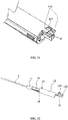
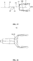
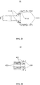
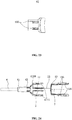
- the structure of the lower shield 42 is shown in FIGS. 21-22 .
- Circular parts in the drawing are circular protrusions 423 which are configured to engage with the circular grooves 4112 of the upper shield 41 to fasten the upper shield 41 and the lower shield 42 together.
- the hold tail 13 is locked at the rear of the needle shield 4, and the spring is in a compressed state.
- the two third pressing portions 135 are pressed towards each other, the two third protrusions 136 are unlocked from the two third engaging portions 4111, respectively, so that the holder tail 13 is unlocked from the rear of the needle shield 4. Then, under the force of the spring, the second tube 12 of the needle holder 1 is pushed to move rearward.
- the auto-retractable blood collection needle of this embodiment is assembled according to the assembling steps in Example 1, and a sheath 6 can be sheathed on the needle 2.
- the operation method of the auto-retractable blood collection needle of this embodiment is same with that of conventional blood collection needles.
- one hand is required to press the handheld portion 4110 of the needle shield 4, and the other hand presses the two third pressing portions 135 of the two sides towards each other to allow the third protrusions 136 to unlock from the two third engaging portions 4111, so that the holder tail 13 is unlocked from the rear of the needle shield 4.
- the second tube 12 of the needle holder 1 is pushed from the built-in sliding sleeve 3 to the locking position of the built-in sliding sleeve to be locked, and then the built-in sliding sleeve 3 is pushed from the needle shield 4 to the locking position of the needle shield to be locked.
- both the needle holder 1 and the built-in sliding sleeve 3 are not allowed to move back and forth, and the needle 2 is fully retracted into the needle shield 4, so that the needle 2 is pulled out of the patient.
- the spring can be removed from the pen-type blood collection needle.
- one hand is required to press the handheld portion 4110 of the needle shield 4, and the other hand presses the two third pressing portions 135 of the two sides towards each other to allow the two third protrusions 136 to unlock from the two third engaging portions 4111, and then the needle holder 1 is pulled rearward, so that the second tube 12 of the needle holder 1 is pulled from the built-in sliding sleeve 3 to the locking position of the built-in sliding sleeve to be locked, and then the built-in sliding sleeve 3 is pulled from the needle shield 4 to the locking position of the built-in sliding sleeve to be locked.
- both the needle holder 1 and the built-in sliding sleeve 3 are not allowed to move forward and backward, and the needle 2 is fully retracted into the needle shield 4, so that the needle 2 is pulled out of the patient.
- configurations of the positioning part and the locking part can be interchanged, that is, the positioning part can also be concave, and the locking part can also be convex if the locking can be realized by the concave and convex configurations.
Landscapes
- Health & Medical Sciences (AREA)
- Life Sciences & Earth Sciences (AREA)
- Engineering & Computer Science (AREA)
- Animal Behavior & Ethology (AREA)
- Hematology (AREA)
- Veterinary Medicine (AREA)
- Public Health (AREA)
- Biomedical Technology (AREA)
- Heart & Thoracic Surgery (AREA)
- General Health & Medical Sciences (AREA)
- Pathology (AREA)
- Surgery (AREA)
- Molecular Biology (AREA)
- Medical Informatics (AREA)
- Biophysics (AREA)
- Physics & Mathematics (AREA)
- Vascular Medicine (AREA)
- Manufacturing & Machinery (AREA)
- Anesthesiology (AREA)
- Environmental & Geological Engineering (AREA)
- Infusion, Injection, And Reservoir Apparatuses (AREA)
- Measurement Of The Respiration, Hearing Ability, Form, And Blood Characteristics Of Living Organisms (AREA)
Applications Claiming Priority (3)
| Application Number | Priority Date | Filing Date | Title |
|---|---|---|---|
| CN201710289637 | 2017-04-27 | ||
| CN201710433613.8A CN107198531A (zh) | 2017-04-27 | 2017-06-09 | 一种针头自动回缩式采血针 |
| PCT/CN2018/090525 WO2018224046A1 (fr) | 2017-04-27 | 2018-06-08 | Aiguille de prélèvement de sang à rétraction automatique d'aiguille |
Publications (4)
| Publication Number | Publication Date |
|---|---|
| EP3636155A1 true EP3636155A1 (fr) | 2020-04-15 |
| EP3636155A4 EP3636155A4 (fr) | 2021-03-24 |
| EP3636155C0 EP3636155C0 (fr) | 2023-06-07 |
| EP3636155B1 EP3636155B1 (fr) | 2023-06-07 |
Family
ID=59906661
Family Applications (1)
| Application Number | Title | Priority Date | Filing Date |
|---|---|---|---|
| EP18813322.7A Active EP3636155B1 (fr) | 2017-04-27 | 2018-06-08 | Aiguille de prélèvement de sang à rétraction automatique d'aiguille |
Country Status (15)
| Country | Link |
|---|---|
| US (1) | US11202869B2 (fr) |
| EP (1) | EP3636155B1 (fr) |
| JP (1) | JP6966576B2 (fr) |
| KR (1) | KR102433742B1 (fr) |
| CN (3) | CN107198531A (fr) |
| AU (1) | AU2018279678B2 (fr) |
| CA (1) | CA3066513C (fr) |
| ES (1) | ES2953678T3 (fr) |
| HU (1) | HUE064274T2 (fr) |
| PH (1) | PH12019502780A1 (fr) |
| PL (1) | PL3636155T3 (fr) |
| RU (1) | RU2730972C1 (fr) |
| SG (1) | SG11201911844QA (fr) |
| WO (1) | WO2018224046A1 (fr) |
| ZA (1) | ZA201908162B (fr) |
Families Citing this family (16)
| Publication number | Priority date | Publication date | Assignee | Title |
|---|---|---|---|---|
| CN107198531A (zh) * | 2017-04-27 | 2017-09-26 | 王祖扬 | 一种针头自动回缩式采血针 |
| CN109316195B (zh) * | 2017-10-12 | 2021-08-03 | 江西丰临医疗科技股份有限公司 | 安全采血器 |
| CN107714054B (zh) * | 2017-11-16 | 2024-04-09 | 成都瑞琦医疗科技有限责任公司 | 专用于对静脉采血针进行防护的机构 |
| CN107823761B (zh) * | 2017-12-08 | 2023-08-18 | 宁波美生医疗器材有限公司 | 一种安全胰岛素笔配套用针 |
| JP7530548B2 (ja) * | 2019-05-28 | 2024-08-08 | 株式会社トップ | 採血用ホルダ |
| USD967402S1 (en) | 2019-06-05 | 2022-10-18 | Aidian Oy | Blood collecting device |
| CN110200639B (zh) * | 2019-07-05 | 2024-08-13 | 兰州大学第二医院 | 一种大小鼠自动心脏采血装置 |
| CN110680347A (zh) * | 2019-10-18 | 2020-01-14 | 上海宝舜医疗器械有限公司 | 一种采血针的按压式安全防护机构 |
| CN111110251B (zh) * | 2020-01-13 | 2022-11-11 | 广州阳普医疗科技股份有限公司 | 一种安全采血针 |
| CN111419245B (zh) * | 2020-03-17 | 2023-12-05 | 天津华鸿科技股份有限公司 | 采血笔 |
| WO2024172839A1 (fr) * | 2023-02-13 | 2024-08-22 | The Monarch Company, Llc | Ensemble prélèvement sanguin |
| USD1071211S1 (en) * | 2023-06-19 | 2025-04-15 | Femasys Inc. | Syringe lock |
| CN116869528B (zh) * | 2023-08-01 | 2026-03-24 | 苏州施莱医疗器械有限公司 | 一种针芯旋转式尾部按压采血器 |
| CN221431786U (zh) * | 2023-08-29 | 2024-07-30 | 普昂(杭州)生命科技有限公司 | 一种弹簧式静脉穿刺针 |
| US20250345581A1 (en) * | 2024-05-07 | 2025-11-13 | Becton, Dickinson And Company | Instrument Delivery Device for Extended Instrument Advancement into an Indwelling Catheter |
| CN120501987B (zh) * | 2025-07-18 | 2025-09-23 | 苏州翰尔西医疗器械开发有限公司 | 一种预灌封自动注射笔 |
Family Cites Families (24)
| Publication number | Priority date | Publication date | Assignee | Title |
|---|---|---|---|---|
| NL9002552A (nl) * | 1990-09-05 | 1992-04-01 | Advanced Protective Injection | Infusie- of transfusienaaldsamenstel. |
| US5328473A (en) * | 1993-04-28 | 1994-07-12 | Becton, Dickinson And Company | Disposable needle holder |
| JP2001259029A (ja) * | 2000-03-21 | 2001-09-25 | Medikit Kk | 安全留置針 |
| BR0110158A (pt) * | 2000-04-18 | 2004-12-28 | Mdc Invest Holdings Inc | Dispositivo médico, e, métodos para infundir fluido em um paciente com um dispositivo médico, para fazer transfusão de um dentre sangue e plasma para dentro e para fora de um paciente com um dispositivo médico e para inserir um fio guia em um paciente usando um dispositivo médico portador de agulha |
| US6673047B2 (en) * | 2001-01-05 | 2004-01-06 | Becton, Dickinson And Company | Blood collection set |
| EP1374934A1 (fr) * | 2002-06-25 | 2004-01-02 | Sergio Restelli | Aiguille papillon avec une sécurité améliorée |
| JP4648615B2 (ja) * | 2003-04-04 | 2011-03-09 | 株式会社ジェイ・エム・エス | 翼付きシールドを有する医療用針装置 |
| US20040236287A1 (en) * | 2003-05-23 | 2004-11-25 | Becton Dickinson & Company | Forward shielding medical needle device |
| KR20080058345A (ko) * | 2005-09-22 | 2008-06-25 | 타이코 헬스케어 그룹 엘피 | 바늘 후퇴 구조체 |
| US8052641B2 (en) * | 2006-06-30 | 2011-11-08 | Nipro Corporation | Indwelling needle with wings |
| CN201182605Y (zh) * | 2008-02-21 | 2009-01-21 | 明辰股份有限公司 | 自动回缩式安全采血器 |
| US8439870B2 (en) * | 2008-09-10 | 2013-05-14 | B. Braun Medical Inc. | Safety needle assembly and methods |
| WO2014063344A1 (fr) * | 2012-10-26 | 2014-05-01 | Zhang Jianming | Dispositif intégral de prélèvement de sang sous vide avec manchon de protection de pointe d'aiguille |
| CN103892846A (zh) * | 2012-12-27 | 2014-07-02 | 汪贤宗 | 安全采血针套 |
| CN103156621B (zh) * | 2013-03-18 | 2014-09-17 | 苏州施莱医疗器械有限公司 | 一种改进型安全采血笔 |
| CN105561433A (zh) * | 2014-10-15 | 2016-05-11 | 江苏采纳医疗科技有限公司 | 自毁式安全医用针 |
| CN104288866B (zh) * | 2014-10-24 | 2015-07-29 | 上海金塔医用器材有限公司 | 一次性使用防针刺静脉输液穿刺针 |
| JP6867101B2 (ja) * | 2015-08-21 | 2021-04-28 | ニプロ株式会社 | 留置針 |
| CN106474593A (zh) * | 2015-08-27 | 2017-03-08 | 王祖扬 | 一种针头自动回缩式安全静脉输液针 |
| CN106474592A (zh) * | 2015-08-27 | 2017-03-08 | 王祖扬 | 一种针头自动回缩式安全静脉采血针 |
| JP6336008B2 (ja) * | 2015-11-23 | 2018-06-06 | ジェムティア メディカル (シャンハイ) インコーポレイテッド | 針刺し装置 |
| CN206198391U (zh) * | 2016-08-16 | 2017-05-31 | 上海金塔医用器材有限公司 | 防针刺结构及防针刺静脉输液穿刺针 |
| CN107281586A (zh) * | 2017-04-27 | 2017-10-24 | 王祖扬 | 一种针头手动回缩式静脉输液针 |
| CN107198531A (zh) * | 2017-04-27 | 2017-09-26 | 王祖扬 | 一种针头自动回缩式采血针 |
-
2017
- 2017-06-09 CN CN201710433613.8A patent/CN107198531A/zh active Pending
-
2018
- 2018-06-08 JP JP2019568037A patent/JP6966576B2/ja active Active
- 2018-06-08 WO PCT/CN2018/090525 patent/WO2018224046A1/fr not_active Ceased
- 2018-06-08 SG SG11201911844QA patent/SG11201911844QA/en unknown
- 2018-06-08 AU AU2018279678A patent/AU2018279678B2/en active Active
- 2018-06-08 EP EP18813322.7A patent/EP3636155B1/fr active Active
- 2018-06-08 RU RU2019144052A patent/RU2730972C1/ru active
- 2018-06-08 PL PL18813322.7T patent/PL3636155T3/pl unknown
- 2018-06-08 HU HUE18813322A patent/HUE064274T2/hu unknown
- 2018-06-08 CN CN201810588985.2A patent/CN108937960B/zh active Active
- 2018-06-08 KR KR1020207000423A patent/KR102433742B1/ko active Active
- 2018-06-08 ES ES18813322T patent/ES2953678T3/es active Active
- 2018-06-08 CN CN201820889087.6U patent/CN209499742U/zh not_active Withdrawn - After Issue
- 2018-06-08 CA CA3066513A patent/CA3066513C/fr active Active
-
2019
- 2019-12-09 US US16/708,065 patent/US11202869B2/en active Active
- 2019-12-09 ZA ZA2019/08162A patent/ZA201908162B/en unknown
- 2019-12-10 PH PH12019502780A patent/PH12019502780A1/en unknown
Also Published As
| Publication number | Publication date |
|---|---|
| HUE064274T2 (hu) | 2024-03-28 |
| ES2953678T3 (es) | 2023-11-15 |
| PL3636155T3 (pl) | 2024-01-29 |
| SG11201911844QA (en) | 2020-01-30 |
| US20200114089A1 (en) | 2020-04-16 |
| WO2018224046A1 (fr) | 2018-12-13 |
| BR112019026055A2 (pt) | 2020-06-23 |
| RU2730972C1 (ru) | 2020-08-26 |
| CN108937960B (zh) | 2023-12-15 |
| ZA201908162B (en) | 2020-05-27 |
| EP3636155A4 (fr) | 2021-03-24 |
| CN108937960A (zh) | 2018-12-07 |
| CA3066513C (fr) | 2022-03-29 |
| KR102433742B1 (ko) | 2022-08-19 |
| CN107198531A (zh) | 2017-09-26 |
| JP6966576B2 (ja) | 2021-11-17 |
| US11202869B2 (en) | 2021-12-21 |
| KR20200017460A (ko) | 2020-02-18 |
| AU2018279678B2 (en) | 2021-06-24 |
| PH12019502780A1 (en) | 2020-10-26 |
| JP2020522360A (ja) | 2020-07-30 |
| CA3066513A1 (fr) | 2018-12-13 |
| EP3636155C0 (fr) | 2023-06-07 |
| EP3636155B1 (fr) | 2023-06-07 |
| AU2018279678A1 (en) | 2020-01-23 |
| CN209499742U (zh) | 2019-10-18 |
Similar Documents
| Publication | Publication Date | Title |
|---|---|---|
| US11202869B2 (en) | Auto-retractable safety blood collection needle | |
| US11679233B2 (en) | Retractable needle catheter insertion device | |
| US7291128B2 (en) | Medical kit comprising a catheter, a needle and its case | |
| EP0433050B1 (fr) | Améliorations pour instruments de prélèvement du sang | |
| WO2008001590A1 (fr) | aiguille à demeure dotée d'ailes | |
| EP3539598B1 (fr) | Aiguille d'injection sécurisée | |
| US20160022177A1 (en) | Safety lancing device | |
| US11338085B2 (en) | Manually-retractable intravenous infusion needle assembly | |
| US20070005014A1 (en) | Disposable safety syringe | |
| CN210903128U (zh) | 导丝操作器的外套锁紧结构 | |
| BR112019026055B1 (pt) | Agulha de coleta de sangue de segurança autorretrátil | |
| CN222488401U (zh) | 一种滑卡连接式安全型留置针 | |
| CN208389096U (zh) | 一种针头手动回缩式静脉输液针 | |
| JP2000342687A (ja) | 安全針 |
Legal Events
| Date | Code | Title | Description |
|---|---|---|---|
| STAA | Information on the status of an ep patent application or granted ep patent |
Free format text: STATUS: THE INTERNATIONAL PUBLICATION HAS BEEN MADE |
|
| PUAI | Public reference made under article 153(3) epc to a published international application that has entered the european phase |
Free format text: ORIGINAL CODE: 0009012 |
|
| STAA | Information on the status of an ep patent application or granted ep patent |
Free format text: STATUS: REQUEST FOR EXAMINATION WAS MADE |
|
| 17P | Request for examination filed |
Effective date: 20191219 |
|
| AK | Designated contracting states |
Kind code of ref document: A1 Designated state(s): AL AT BE BG CH CY CZ DE DK EE ES FI FR GB GR HR HU IE IS IT LI LT LU LV MC MK MT NL NO PL PT RO RS SE SI SK SM TR |
|
| AX | Request for extension of the european patent |
Extension state: BA ME |
|
| DAV | Request for validation of the european patent (deleted) | ||
| DAX | Request for extension of the european patent (deleted) | ||
| A4 | Supplementary search report drawn up and despatched |
Effective date: 20210222 |
|
| RIC1 | Information provided on ipc code assigned before grant |
Ipc: A61B 5/153 20060101ALI20210217BHEP Ipc: A61B 5/15 20060101AFI20210217BHEP |
|
| GRAP | Despatch of communication of intention to grant a patent |
Free format text: ORIGINAL CODE: EPIDOSNIGR1 |
|
| STAA | Information on the status of an ep patent application or granted ep patent |
Free format text: STATUS: GRANT OF PATENT IS INTENDED |
|
| INTG | Intention to grant announced |
Effective date: 20220919 |
|
| GRAS | Grant fee paid |
Free format text: ORIGINAL CODE: EPIDOSNIGR3 |
|
| GRAA | (expected) grant |
Free format text: ORIGINAL CODE: 0009210 |
|
| STAA | Information on the status of an ep patent application or granted ep patent |
Free format text: STATUS: THE PATENT HAS BEEN GRANTED |
|
| AK | Designated contracting states |
Kind code of ref document: B1 Designated state(s): AL AT BE BG CH CY CZ DE DK EE ES FI FR GB GR HR HU IE IS IT LI LT LU LV MC MK MT NL NO PL PT RO RS SE SI SK SM TR |
|
| REG | Reference to a national code |
Ref country code: GB Ref legal event code: FG4D |
|
| REG | Reference to a national code |
Ref country code: CH Ref legal event code: EP Ref country code: AT Ref legal event code: REF Ref document number: 1572362 Country of ref document: AT Kind code of ref document: T Effective date: 20230615 |
|
| REG | Reference to a national code |
Ref country code: DE Ref legal event code: R096 Ref document number: 602018051372 Country of ref document: DE |
|
| U01 | Request for unitary effect filed |
Effective date: 20230628 |
|
| U07 | Unitary effect registered |
Designated state(s): AT BE BG DE DK EE FI FR IT LT LU LV MT NL PT SE SI Effective date: 20230706 |
|
| U20 | Renewal fee for the european patent with unitary effect paid |
Year of fee payment: 6 Effective date: 20230720 |
|
| REG | Reference to a national code |
Ref country code: LT Ref legal event code: MG9D |
|
| PG25 | Lapsed in a contracting state [announced via postgrant information from national office to epo] |
Ref country code: NO Free format text: LAPSE BECAUSE OF FAILURE TO SUBMIT A TRANSLATION OF THE DESCRIPTION OR TO PAY THE FEE WITHIN THE PRESCRIBED TIME-LIMIT Effective date: 20230907 |
|
| REG | Reference to a national code |
Ref country code: ES Ref legal event code: FG2A Ref document number: 2953678 Country of ref document: ES Kind code of ref document: T3 Effective date: 20231115 |
|
| PG25 | Lapsed in a contracting state [announced via postgrant information from national office to epo] |
Ref country code: RS Free format text: LAPSE BECAUSE OF FAILURE TO SUBMIT A TRANSLATION OF THE DESCRIPTION OR TO PAY THE FEE WITHIN THE PRESCRIBED TIME-LIMIT Effective date: 20230607 Ref country code: HR Free format text: LAPSE BECAUSE OF FAILURE TO SUBMIT A TRANSLATION OF THE DESCRIPTION OR TO PAY THE FEE WITHIN THE PRESCRIBED TIME-LIMIT Effective date: 20230607 Ref country code: GR Free format text: LAPSE BECAUSE OF FAILURE TO SUBMIT A TRANSLATION OF THE DESCRIPTION OR TO PAY THE FEE WITHIN THE PRESCRIBED TIME-LIMIT Effective date: 20230908 |
|
| PG25 | Lapsed in a contracting state [announced via postgrant information from national office to epo] |
Ref country code: SK Free format text: LAPSE BECAUSE OF FAILURE TO SUBMIT A TRANSLATION OF THE DESCRIPTION OR TO PAY THE FEE WITHIN THE PRESCRIBED TIME-LIMIT Effective date: 20230607 |
|
| PG25 | Lapsed in a contracting state [announced via postgrant information from national office to epo] |
Ref country code: IS Free format text: LAPSE BECAUSE OF FAILURE TO SUBMIT A TRANSLATION OF THE DESCRIPTION OR TO PAY THE FEE WITHIN THE PRESCRIBED TIME-LIMIT Effective date: 20231007 |
|
| PG25 | Lapsed in a contracting state [announced via postgrant information from national office to epo] |
Ref country code: SM Free format text: LAPSE BECAUSE OF FAILURE TO SUBMIT A TRANSLATION OF THE DESCRIPTION OR TO PAY THE FEE WITHIN THE PRESCRIBED TIME-LIMIT Effective date: 20230607 Ref country code: SK Free format text: LAPSE BECAUSE OF FAILURE TO SUBMIT A TRANSLATION OF THE DESCRIPTION OR TO PAY THE FEE WITHIN THE PRESCRIBED TIME-LIMIT Effective date: 20230607 Ref country code: RO Free format text: LAPSE BECAUSE OF FAILURE TO SUBMIT A TRANSLATION OF THE DESCRIPTION OR TO PAY THE FEE WITHIN THE PRESCRIBED TIME-LIMIT Effective date: 20230607 Ref country code: IS Free format text: LAPSE BECAUSE OF FAILURE TO SUBMIT A TRANSLATION OF THE DESCRIPTION OR TO PAY THE FEE WITHIN THE PRESCRIBED TIME-LIMIT Effective date: 20231007 |
|
| REG | Reference to a national code |
Ref country code: DE Ref legal event code: R097 Ref document number: 602018051372 Country of ref document: DE |
|
| PG25 | Lapsed in a contracting state [announced via postgrant information from national office to epo] |
Ref country code: MC Free format text: LAPSE BECAUSE OF FAILURE TO SUBMIT A TRANSLATION OF THE DESCRIPTION OR TO PAY THE FEE WITHIN THE PRESCRIBED TIME-LIMIT Effective date: 20230607 |
|
| REG | Reference to a national code |
Ref country code: IE Ref legal event code: MM4A |
|
| REG | Reference to a national code |
Ref country code: HU Ref legal event code: AG4A Ref document number: E064274 Country of ref document: HU |
|
| PG25 | Lapsed in a contracting state [announced via postgrant information from national office to epo] |
Ref country code: MC Free format text: LAPSE BECAUSE OF FAILURE TO SUBMIT A TRANSLATION OF THE DESCRIPTION OR TO PAY THE FEE WITHIN THE PRESCRIBED TIME-LIMIT Effective date: 20230607 |
|
| PLBE | No opposition filed within time limit |
Free format text: ORIGINAL CODE: 0009261 |
|
| STAA | Information on the status of an ep patent application or granted ep patent |
Free format text: STATUS: NO OPPOSITION FILED WITHIN TIME LIMIT |
|
| PG25 | Lapsed in a contracting state [announced via postgrant information from national office to epo] |
Ref country code: IE Free format text: LAPSE BECAUSE OF NON-PAYMENT OF DUE FEES Effective date: 20230608 |
|
| PG25 | Lapsed in a contracting state [announced via postgrant information from national office to epo] |
Ref country code: IE Free format text: LAPSE BECAUSE OF NON-PAYMENT OF DUE FEES Effective date: 20230608 |
|
| 26N | No opposition filed |
Effective date: 20240308 |
|
| U20 | Renewal fee for the european patent with unitary effect paid |
Year of fee payment: 7 Effective date: 20240511 |
|
| PGFP | Annual fee paid to national office [announced via postgrant information from national office to epo] |
Ref country code: PL Payment date: 20250523 Year of fee payment: 8 |
|
| U20 | Renewal fee for the european patent with unitary effect paid |
Year of fee payment: 8 Effective date: 20250603 |
|
| PGFP | Annual fee paid to national office [announced via postgrant information from national office to epo] |
Ref country code: GB Payment date: 20250603 Year of fee payment: 8 |
|
| PGFP | Annual fee paid to national office [announced via postgrant information from national office to epo] |
Ref country code: HU Payment date: 20250526 Year of fee payment: 8 |
|
| PG25 | Lapsed in a contracting state [announced via postgrant information from national office to epo] |
Ref country code: CY Free format text: LAPSE BECAUSE OF FAILURE TO SUBMIT A TRANSLATION OF THE DESCRIPTION OR TO PAY THE FEE WITHIN THE PRESCRIBED TIME-LIMIT; INVALID AB INITIO Effective date: 20180608 |
|
| PGFP | Annual fee paid to national office [announced via postgrant information from national office to epo] |
Ref country code: TR Payment date: 20250527 Year of fee payment: 8 |
|
| PGFP | Annual fee paid to national office [announced via postgrant information from national office to epo] |
Ref country code: CZ Payment date: 20250526 Year of fee payment: 8 |
|
| PGFP | Annual fee paid to national office [announced via postgrant information from national office to epo] |
Ref country code: ES Payment date: 20250714 Year of fee payment: 8 |
|
| PGFP | Annual fee paid to national office [announced via postgrant information from national office to epo] |
Ref country code: CH Payment date: 20250826 Year of fee payment: 8 |