EP3636213A1 - Gabarit d'alignement de prothèse dentaire de référence, kit de préparation de prothèses dentaires, et procédé de préparation de prothèses dentaires utilisant ce dernier - Google Patents
Gabarit d'alignement de prothèse dentaire de référence, kit de préparation de prothèses dentaires, et procédé de préparation de prothèses dentaires utilisant ce dernier Download PDFInfo
- Publication number
- EP3636213A1 EP3636213A1 EP18798037.0A EP18798037A EP3636213A1 EP 3636213 A1 EP3636213 A1 EP 3636213A1 EP 18798037 A EP18798037 A EP 18798037A EP 3636213 A1 EP3636213 A1 EP 3636213A1
- Authority
- EP
- European Patent Office
- Prior art keywords
- standard
- denture
- standard denture
- alignment jig
- dentures
- Prior art date
- Legal status (The legal status is an assumption and is not a legal conclusion. Google has not performed a legal analysis and makes no representation as to the accuracy of the status listed.)
- Granted
Links
Images


Classifications
-
- A—HUMAN NECESSITIES
- A61—MEDICAL OR VETERINARY SCIENCE; HYGIENE
- A61C—DENTISTRY; APPARATUS OR METHODS FOR ORAL OR DENTAL HYGIENE
- A61C11/00—Dental articulators, i.e. for simulating movement of the temporo-mandibular joints; Articulation forms or mouldings
- A61C11/001—Dental articulators, i.e. for simulating movement of the temporo-mandibular joints; Articulation forms or mouldings non-pivoting
-
- A—HUMAN NECESSITIES
- A61—MEDICAL OR VETERINARY SCIENCE; HYGIENE
- A61C—DENTISTRY; APPARATUS OR METHODS FOR ORAL OR DENTAL HYGIENE
- A61C19/00—Dental auxiliary appliances
- A61C19/04—Measuring instruments specially adapted for dentistry
-
- A—HUMAN NECESSITIES
- A61—MEDICAL OR VETERINARY SCIENCE; HYGIENE
- A61C—DENTISTRY; APPARATUS OR METHODS FOR ORAL OR DENTAL HYGIENE
- A61C11/00—Dental articulators, i.e. for simulating movement of the temporo-mandibular joints; Articulation forms or mouldings
- A61C11/006—Dental articulators, i.e. for simulating movement of the temporo-mandibular joints; Articulation forms or mouldings with an occlusal plate
-
- A—HUMAN NECESSITIES
- A61—MEDICAL OR VETERINARY SCIENCE; HYGIENE
- A61C—DENTISTRY; APPARATUS OR METHODS FOR ORAL OR DENTAL HYGIENE
- A61C13/00—Dental prostheses; Making same
-
- A—HUMAN NECESSITIES
- A61—MEDICAL OR VETERINARY SCIENCE; HYGIENE
- A61C—DENTISTRY; APPARATUS OR METHODS FOR ORAL OR DENTAL HYGIENE
- A61C13/00—Dental prostheses; Making same
- A61C13/0001—In-situ dentures; Trial or temporary dentures
-
- A—HUMAN NECESSITIES
- A61—MEDICAL OR VETERINARY SCIENCE; HYGIENE
- A61C—DENTISTRY; APPARATUS OR METHODS FOR ORAL OR DENTAL HYGIENE
- A61C13/00—Dental prostheses; Making same
- A61C13/0024—Repairing or adjusting dentures; Location of irritating zones
-
- A—HUMAN NECESSITIES
- A61—MEDICAL OR VETERINARY SCIENCE; HYGIENE
- A61C—DENTISTRY; APPARATUS OR METHODS FOR ORAL OR DENTAL HYGIENE
- A61C13/00—Dental prostheses; Making same
- A61C13/0025—Linings
-
- A—HUMAN NECESSITIES
- A61—MEDICAL OR VETERINARY SCIENCE; HYGIENE
- A61C—DENTISTRY; APPARATUS OR METHODS FOR ORAL OR DENTAL HYGIENE
- A61C13/00—Dental prostheses; Making same
- A61C13/10—Fastening of artificial teeth to denture palates or the like
- A61C13/1026—Shock absorbers
-
- A—HUMAN NECESSITIES
- A61—MEDICAL OR VETERINARY SCIENCE; HYGIENE
- A61C—DENTISTRY; APPARATUS OR METHODS FOR ORAL OR DENTAL HYGIENE
- A61C13/00—Dental prostheses; Making same
- A61C13/225—Fastening prostheses in the mouth
- A61C13/26—Dentures without palates; Partial dentures, e.g. bridges
-
- A—HUMAN NECESSITIES
- A61—MEDICAL OR VETERINARY SCIENCE; HYGIENE
- A61C—DENTISTRY; APPARATUS OR METHODS FOR ORAL OR DENTAL HYGIENE
- A61C19/00—Dental auxiliary appliances
- A61C19/04—Measuring instruments specially adapted for dentistry
- A61C19/05—Measuring instruments specially adapted for dentistry for determining occlusion
-
- A—HUMAN NECESSITIES
- A61—MEDICAL OR VETERINARY SCIENCE; HYGIENE
- A61C—DENTISTRY; APPARATUS OR METHODS FOR ORAL OR DENTAL HYGIENE
- A61C11/00—Dental articulators, i.e. for simulating movement of the temporo-mandibular joints; Articulation forms or mouldings
-
- A—HUMAN NECESSITIES
- A61—MEDICAL OR VETERINARY SCIENCE; HYGIENE
- A61C—DENTISTRY; APPARATUS OR METHODS FOR ORAL OR DENTAL HYGIENE
- A61C9/00—Impression cups, i.e. impression trays; Impression methods
- A61C9/0006—Impression trays
Definitions
- the present invention relates to a standard denture alignment jig, a denture preparation kit, and a method for preparing a denture using the jig and the kit.
- the present invention relates to a standard denture alignment jig, a denture preparation kit, and a method for preparing a denture using the jig and the kit in order to place a standard denture in an appropriate position, for example, in the oral cavity of a patient.
- edentulous people have the oral cavity shaped differently from each other.
- the size of the alveolar bone, an absorbed amount of the bone, and a state of the mucous membrane vary from individual to individual.
- it is required to prepare a denture from a model of each individual according to a known procedure in the related art, which takes a lot of time for preparation (customization).
- Patent Literature 1 a standard denture of a standardized size has been proposed in order to easily prepare a denture with a good fit.
- Patent Literature 1 a standard denture of a standardized size has been proposed in order to easily prepare a denture with a good fit.
- a standardized standard denture and a relining material such as a hard relining material, it is possible to yield a denture with a good fit (standard denture) in a short time by intraoral relining without technical operations using a plaster model.
- a relining material before curing is applied to an inner surface of the base of the standard denture and inserted into an oral cavity or an articulator mounted with maxillary and mandibular edentulous jaw models. Then, the relining material is fluidized, and the shape of the mucous membrane is registered on the relining material. At this time, it is required to maintain the standard denture in an appropriate position until the relining material cures.
- using only the standard denture makes it difficult to maintain the standard denture in an appropriate position and may cause a positional shift. Due to the positional shift, some people have difficulty in biting hard foods or have a temporomandibular joint pain after long-term use.
- Patent Literature 1 JP 2015-165850 A
- An object of the present invention is to provide a standard denture alignment jig that facilitates positioning of a ready-made standard denture, to which a relining material is applied, in an appropriate position, for example, in the oral cavity of a patient.
- Another object of the present invention is to provide a denture preparation kit that includes the standard denture alignment jig and a relining material.
- Still another object of the present invention is to provide a method for preparing a denture using the standard denture alignment jig.
- the inventors of the present invention have found that retention of standard dentures in a jig (tray) having a predetermined structure makes it possible to maintain appropriate occlusion between maxillary and mandibular standard dentures and to place the standard dentures in predetermined positions until a relining material cures.
- the inventors of the present invention have found that the use of a jig having a predetermined structure enables further appropriate positioning of standard dentures, whereby completing the present invention.
- a "standard denture” refers to an already-made denture in which artificial teeth are arranged in advance and to which a relining material is not applied.
- a pair of standard dentures represents a maxillary standard denture and a mandibular standard denture.
- a complete dentition represents a dentition including 14 teeth from the left second molar to the right second molar.
- the standard denture alignment jig according to an embodiment of the present invention is applicable not only to the oral cavity of a patient (human) but also to maxillary and mandibular edentulous jaw models.
- a method for preparing a denture using the standard denture alignment jig according to an embodiment of the present invention is applicable to maxillary and mandibular edentulous jaw models and is not applicable to a case where the jig is directly applied to a patient (human).
- This specification will describe a method for preparing a denture using the standard denture alignment jig according to an embodiment of the present invention, including a case where the jig is applied directly to a patient (human).
- the horizontal guide of the standard denture alignment jig is brought into contact with the imaginary occlusal plane of the maxillary and mandibular edentulous jaw models, whereby adjusting vertical positions of the standard denture easily.
- a standard denture alignment jig a denture preparation kit, and a method for preparing a denture according to an embodiment of the present invention
- Such a denture significantly reduces the burden of a dentist, a dental technician, and a patient.
- the terms “perpendicular” and “orthogonal” represents not only a 90-degree angle but also 80- to 100-degree angles. Furthermore, the term “parallel” represents not only “perfectly parallel” but also "plus or minus 10 degrees about a perfect parallel line.
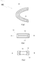
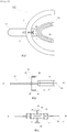
- Fig. 1(a) is a plan view
- Fig. 1(b) is a side view
- Fig. 1(c) is a front view of an exemplary structure of a standard denture alignment jig according to an embodiment of the present invention.
- the bottom view is substantially equal to the plan view
- the right side view is substantially symmetric with the left side view.
- the reference numeral 100 denotes a standard denture alignment jig according to an embodiment of the present invention
- the reference numeral 13 denotes a standard denture retention unit.
- the standard denture retention unit 13 is provided with a maxillary denture retention groove 15 and a mandibular standard denture retention groove 17.
- line A-B represents an occlusal plane of standard dentures.
- the standard denture retention unit 13 Since the standard denture retention unit 13 is inserted into an oral cavity or the like, the standard denture retention unit 13 is preferably small in size and has sufficient durability. Furthermore, the standard denture retention unit 13 is preferably configured to retain the standard dentures by its appropriate elasticity. Although not limited to the following examples, the standard denture retention unit 13 may include, for example, an acrylic resin, polyamide, polyurethane, polyethylene, polypropylene, or silicon rubber.
- the maxillary denture retention groove 15 and the mandibular standard denture retention groove 17 formed in the standard denture retention unit 13 of the standard denture alignment jig 100 may have a structure that enables temporary fixation of a maxillary standard denture 91 and a mandibular standard denture 93 which are to be described.
- the standard denture retention unit 13 may include an elastic material, and those grooves may be slightly smaller than the standard dentures.
- the standard denture alignment jig 100 is used in the following manner.
- the maxillary standard denture 91 and the mandibular standard denture 93 are respectively fitted in the maxillary denture retention groove 15 and the mandibular standard denture retention groove 17 of the standard denture alignment jig 101, while predetermined occlusion is maintained. Accordingly, the standard denture alignment jig 100 retains a pair of standard dentures while maintaining the predetermined occlusion.
- the standard denture alignment jig 100 that retains the pair of standard dentures is inserted into a human oral cavity or into an articulator to which maxillary and mandibular edentulous jaw models are fixed, while the predetermined occlusion between the maxillary and mandibular standard dentures is maintained. Therefore, the use of the standard denture alignment jig 100 according to an embodiment of the present invention enables adjustment of positions in an oral cavity or the like, while the predetermined occlusion between the maxillary and mandibular standard dentures is maintained.
- a standard denture alignment jig that includes a handle.
- the handle is connected to a standard denture retention unit and may have any shape as long as the handle can be easily retained by a hand.
- the handle may have a bar shape, a flat plate shape, or a shape with protrusions and recesses that suit fingers.
- the plane of the handle may be perpendicular, parallel, or oblique to an occlusal plane of standard dentures.
- the handle preferably has a flat plate shape having the plane parallel to an occlusal plane of standard dentures.
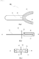
- Fig. 2(a) is a plan view
- Fig. 2(b) is a side view
- Fig. 2(c) is a front view of an exemplary structure of a standard denture alignment jig according to an embodiment of the present invention.
- the bottom view is substantially equal to the plan view
- the right side view is substantially symmetric with the left side view.
- the reference numeral 101 denotes a standard denture alignment jig according to an embodiment of the present invention that includes a handle
- the reference numeral 11 denotes a handle connected to a standard denture retention unit 13.
- the handle 11 of the standard denture alignment jig 101 has a certain length long enough to control a pair of standard dentures from outside a human oral cavity.
- the handle 11 has a length of, typically, 50 to 200 mm and, preferably, 60 to 180 mm.
- incisal edges of maxillary anterior teeth of the standard dentures should be coplanar with and a part of the upper or lower surface of the handle. Particularly, it is preferable that the incisal edges of the maxillary anterior teeth of the standard dentures and a part of the lower surface of the handle should be coplanar.
- the handle preferably has a thickness of 1 to 3 mm, and particularly preferably, 2 mm. By setting the thickness of the handle within such a range, it is possible to set a position of the incisal edges of the anterior teeth according to the positional relationship between the handle and the upper lip and/or the lower lip.
- the standard denture retention unit 13 is connected to the handle 11, and the connection between those members may be performed by integral molding. Alternatively, the handle 11 and the standard denture retention unit 13 may be detachable.
- the standard denture alignment jig 101 is used in the following manner.
- Fig. 8 is a view of the standard denture alignment jig according to an embodiment of the present invention in use.
- the maxillary standard denture 91 and the mandibular standard denture 93 are respectively fitted in the maxillary denture retention groove 15 and the mandibular standard denture retention groove 17 of the standard denture alignment jig 101, while predetermined occlusion is maintained. Accordingly, the standard denture alignment jig 101 retains a pair of standard dentures while maintaining the predetermined occlusion.
- the standard denture alignment jig 101 holding the maxillary standard denture 91 and the mandibular standard denture 93 is inserted into a human oral cavity or an articulator to which maxillary and mandibular edentulous jaw models are fixed. Then, the handle 11 is externally controlled so as to adjust positions of the maxillary standard denture 91 and the mandibular standard denture 93.
- the median guide may be a guide that enables us to check the median line of a standard denture and may be arranged in any position of the alignment jig.
- the median guide may have any shape.
- the median guide may be a pin, a protrusion, a groove, or a print disposed on a denture retention unit.
- a pin, a protrusion, a groove, or a print may be disposed on a handle connected to the denture retention unit.
- the median guide may guide vertical positions of standard dentures by the length of the pin.
- a gauge may be separately disposed in the alignment jig, or a gauge may be disposed in the median guide itself.
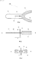
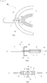
- Fig. 3(a) is a plan view
- Fig. 3(b) is a side view
- Fig. 3(c) is a front view of an exemplary structure of a standard denture alignment jig according to an embodiment of the present invention including a median guide.
- the bottom view is substantially equal to the plan view
- the right side view is substantially symmetric with the left side view.
- Components same as those in Figs. 2(a) to 2(c) are denoted by the same reference numerals and will not be described.
- the reference numeral 102 denotes a standard denture alignment jig according to an embodiment of the present invention that includes a median guide
- the reference numeral 21 denotes a median guide connected to a handle 11.
- the median guide 21 may be formed on either the upper or lower part of the handle 11 or may be formed on both the upper and lower parts of the handle 11 as shown in Fig. 3(b) .
- the median guide 21 may be a pin arranged perpendicular to an occlusal plane as shown in Figs. 3(a) to 3(c) .
- the median guide 21 may be a protrusion, a groove, or a print.
- the median guide is preferably a pin having a length of, preferably, 30 to 60 mm, and more preferably, 35 to 55 mm.
- the pin may expand and contract in a multiple-step or stepless manner.
- a pin having a length in the above range facilitates detection of an inclination of a denture.
- a relative position between a predetermined portion of the articulator and one end of a pin is adjusted so that the relative position is used as an index of vertical positions of standard dentures.
- This pin (median indicating pin) is preferably attached to the handle 11 slidably in a direction parallel to an occlusal plane of standard dentures.
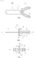
- Fig. 4(a) is a plan view
- Fig. 4(b) is a side view
- Fig. 4(c) is a front view of an exemplary structure of a standard denture alignment jig according to an embodiment of the present invention including a median indicating pin disposed in a slidable manner.
- Components same as those in Figs. 3(a) to 3(c) are denoted by the same reference numerals and will not be described.
- a slide groove 31 is formed in a handle 11, and a median indicating pin 21 is disposed slidably along the groove within a range indicated by symbol C in Fig. 4 (b) .
- reference numeral 33 denotes a nut.
- the median indicating pin 21 becomes slidable along the groove 31 when the nut 33 is loosened.
- the median indicating pin 21 is fixed in an intended position.
- the standard denture alignment jig 102 is used in the following manner.
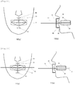
- Fig. 9(a) is a front view and Fig. 9(b) is a side view of the standard denture alignment jig according to an embodiment of the present invention in use.
- the maxillary standard denture 91 and the mandibular standard denture 93 are respectively fitted in the maxillary denture retention groove 15 and the mandibular standard denture retention groove 17 of the standard denture alignment jig 102, while predetermined occlusion is maintained. Accordingly, the standard denture alignment jig 102 retains a pair of standard dentures while maintaining the predetermined occlusion.
- the dentures are fitted in such a manner that a median position of the central incisor of each standard denture aligns with the median guide (median indicating pin) 21.
- the standard denture alignment jig 102 holding the maxillary standard denture 91 and the mandibular standard denture 93 is inserted into a human oral cavity or an articulator to which maxillary and mandibular edentulous jaw models are fixed. Then, the handle 11 is externally controlled so as to adjust positions of the maxillary standard denture 91 and the mandibular standard denture 93. Since the standard denture alignment jig 102 includes the median guide 21, using this median guide 21 facilitates alignment from outside the oral cavity of a patient or from outside the articulator.
- the median indicating pin also serves as an index for adjusting positions of standard dentures to appropriate positions in a depth direction in the oral cavity or the articulator.
- a position of the median indicating pin is appropriately adjusted according to the size of a human face or an articulator.
- a standard denture alignment jig that includes a rod for setting anteroposterior positions of standard dentures in an oral cavity or an articulator.
- the rod may be placed in any position of the alignment jig.
- the rod may have any shape.
- the rod may be disposed on any of a standard denture retention unit, a handle, and a median guide. Since anteroposterior positions of the rod are accurately set by letting the rod contact a face or a portion corresponding to the median line of an articulator to which edentulous jaw models are fixed, the rod is preferably disposed on a median indicating pin or a median guide.
- the rod may expand and contract in a multiple-step or stepless manner.
- Fig. 5(a) is a plan view
- Fig. 5(b) is a side view
- Fig. 5(c) is a front view of an exemplary structure of a standard denture alignment jig according to an embodiment of the present invention including a rod attached in a direction orthogonal to a median indicating pin.
- the bottom view is substantially equal to the plan view
- the right side view is substantially symmetric with the left side view.
- Components same as those in Figs. 1(a) to 4(c) are denoted by the same reference numerals and will not be described.
- the reference numeral 104 denotes a standard denture alignment jig according to an embodiment of the present invention
- the reference numerals 41 and 45 denote rods
- the reference numerals 43 and 47 denote contact portions connected to a tip of the rod 41.
- the rod 41 is attached in a direction orthogonal to a median indicating pin 21 provided on the upper side of a handle 11 (that is, the maxillary side) and in a direction parallel to a longitudinal direction of the handle 11.
- the rod 45 is attached in a direction orthogonal to the median indicating pin 21 provided on the lower side of the handle 11(that is, the mandibular side) and parallel to the longitudinal direction of the handle 11.
- the rods 41 and 45 may be formed in an integrated manner with the median indicating pin. Furthermore, it is preferable that the median indicating pin 21 should be slidably attached to the handle 11 in a direction parallel to an occlusal plane of standard dentures.
- the contact portions 43 and 47 are portions that contact a human face or a surface of an articulator but are not always required in the present invention.
- a tip of a rod may directly contact a human face or a surface of an articulator.
- the contact portions 43 and 47 may be formed in an integrated manner with the rods 41 and 45.
- the rods 41 and 45 are preferably attached to the handle 11 slidably in a direction parallel to the occlusal plane of the standard dentures and a direction parallel to a longitudinal direction of the handle 11.
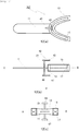
- Fig. 12(a) is a plan view
- Fig. 12(b) is a side view
- Fig. 12(c) is a front view of an exemplary structure of a standard denture alignment jig according to an embodiment of the present invention including a rod disposed in a slidable manner.
- the rods 42 and 46 are arranged in a direction parallel to an occlusal plane of standard dentures, being slidable within a range indicated by symbol D in Fig. 12 (b) .
- the standard denture alignment jig 104 is used in the following manner.
- Fig. 10(a) is a front view and Fig. 10(b) is a side view of the standard denture alignment jig according to an embodiment of the present invention in use.
- the maxillary standard denture 91 and the mandibular standard denture 93 are respectively fitted in the maxillary denture retention groove 15 and the mandibular standard denture retention groove 17 of the standard denture alignment jig 104, while predetermined occlusion is maintained.
- the dentures are fitted in such a manner that a median position of the central incisor of each standard denture aligns with the median guide (median indicating pin) 21. Accordingly, the standard denture alignment jig 104 retains a pair of standard dentures while maintaining the predetermined occlusion.
- the standard denture alignment jig 104 holding the maxillary standard denture 91 and the mandibular standard denture 93 is inserted into a human oral cavity or an articulator to which maxillary and mandibular edentulous jaw models are fixed. Then, the handle 11 is externally controlled so as to adjust positions of the maxillary standard denture 91 and the mandibular standard denture 93.
- the contact portion 43 on the maxillary side is brought into contact with the subnasal point or the lowest point of the maxillary vestibular portion of the occlusal models.
- the contact portion 47 on the mandibular side is brought into contact with the mental protuberance or the lowest point of the mandibular vestibular portion of the models.
- the standard denture alignment jig 104 includes the rods 41 and 45, bringing a tip of a rod into contact with a part of the face of a patient or with the articulator makes it easier to adjust positions of the standard dentures to appropriate positions in a depth direction in the oral cavity or the articulator.
- a standard denture alignment jig including a horizontal guide that indicates an occlusal plane of the standard dentures.
- the horizontal guide may have any shape as long as the horizontal guide has an element indicating the occlusal plane and may be placed in any position of the standard denture alignment jig.
- a pin, a blade, a groove, a print, or a plurality of protrusions arranged in parallel with the occlusal plane may be arranged on a denture retention unit, a handle, or a median guide.
- the handle itself connected to the denture retention unit may be used as the horizontal guide. From a viewpoint of visibility, the horizontal guide is preferably a blade disposed in the handle.
- the blade preferably has a shape that conforms with a face.
- the blade, or the horizontal guide is preferably adjustable to a position where the blade is easily seen with respect to a human face or an articulator to which edentulous jaw models are fixed.
- the blade may have a slide mechanism that slides anteroposteriorly and vertically.
- Fig. 6(a) is a plan view
- Fig. 6(b) is a side view
- Fig. 6(c) is a front view of an exemplary structure of a standard denture alignment jig according to an embodiment of the present invention including the horizontal guide that indicates an occlusal plane of standard dentures.
- Components same as those in Figs. 1(a) to 5(c) are denoted by the same reference numerals and will not be described.
- the reference numeral 105 denotes a standard denture alignment jig according to an embodiment of the present invention
- the reference numeral 51 denotes a horizontal guide that indicates an occlusal plane of standard dentures.
- This horizontal guide 51 is a blade connected to a handle, having a U- or V-shape so as to conform with the shape of a human face or an articulator (in Figs. 5(a) to 5(c) , the horizontal guide 51 has a U-shape).
- the horizontal guide 51 may be configured to change in shape.
- Fig. 7(a) is a plan view
- Fig. 7(b) is a side view
- Fig. 7(c) is a front view of another exemplary structure of a standard denture alignment jig according to an embodiment of the present invention including the horizontal guide that indicates an occlusal plane of standard dentures.
- Components same as those in Figs. 1(a) to 6(c) are denoted by the same reference numerals and will not be described.
- the reference numeral 106 denotes a standard denture alignment jig according to an embodiment of the present invention
- the reference numerals 61 and 63 denote blades.
- the two blades 61 and 63 are horizontal guides indicating the occlusal plane of the standard dentures.
- the blades 61 and 63 are rotatable about a median indicating pin that functions as a fulcrum. In other words, the blades 61 and 63 are configured to adjust the shape of the horizontal guide by rotating according to the size of a human face or the size of an articulator.
- the standard denture alignment jig 105 is used in the following manner. Note that the standard denture alignment jig 106 is used in a similar manner.
- Fig. 11(a) is a front view and Fig. 11(b) is a side view of the standard denture alignment jig according to an embodiment of the present invention in use.
- the maxillary standard denture 91 and the mandibular standard denture 93 are respectively fitted in the maxillary denture retention groove 15 and the mandibular standard denture retention groove 17 of the standard denture alignment jig 105, while predetermined occlusion is maintained.
- the dentures are fitted in such a manner that a median position of the central incisor of each standard denture aligns with the median guide (median indicating pin) 21. Accordingly, the standard denture alignment jig 105 retains a pair of standard dentures while maintaining the predetermined occlusion.
- the standard denture alignment jig 105 holding the maxillary standard denture 91 and the mandibular standard denture 93 is inserted into a human oral cavity or an articulator to which maxillary and mandibular edentulous jaw models are fixed. Then, the handle 11 is externally controlled so as to adjust positions of the maxillary standard denture 91 and the mandibular standard denture 93.
- checking anteroposterior and vertical inclinations of the horizontal guide 51 makes it easier to adjust a position of an occlusal plane of the standard dentures to an appropriate position in the oral cavity or the articulator.
- aligning the horizontal guide 51 with an imaginary occlusal plane of the maxillary and mandibular edentulous jaw models makes it easier to adjust a position of the occlusal plane of the standard dentures to an appropriate position.
- a partial denture preparation kit includes the standard denture alignment jig and a standard denture, and may also include a relining material.
- the standard denture is a ready-made denture having a predetermined shape.
- a standard denture disclosed in JP 2015-165850 A is employable. Since the standard denture has a predetermined shape, the standard denture is easily fitted to the oral shape of a patient by simply applying a relining material. In other words, the use of a ready-made denture reduces the time for preparing a denture.
- a known material is employable as the relining material without any limitation.
- the relining material include poly (meth) acrylate resin, polyolefin resin, polyamide resin, polyester resin, polyether resin, polynitrile resin, polyvinyl resin, cellulose resin, fluorine resin, imide resin, and silicon resin.
- the standard denture alignment jig is made to retain a standard denture while predetermined occlusion is maintained.
- a relining material is applied to an inner surface of this standard denture, and then, as described above, the jig that retains the standard denture is inserted into a human oral cavity or an articulator. Then, the shape is registered on the relining material applied to the standard denture. Accordingly, the inner surface shape of the model set in the human oral cavity or the articulator is registered on the relining material, whereby preparing a denture.
- the alignment jig used here was one shown in Figs. 2(a) to 2(c) .
- Each standard denture was set in a standard denture retention unit, and a hard relining material was applied to an inner surface of each standard denture.
- the standard dentures were inserted into the oral cavity of a manikin.
- the mucosal surface shape was registered on the relining material, and the relining material was cured, whereby preparing dentures.
- Dentures were prepared in a similar manner to Example 1 except that an alignment jig used here was one that includes a handle as shown in Figs. 2(a) to 2(c) . At the time of preparation, a median indicating line was aligned with the median line of a manikin.
- Dentures were prepared in a similar manner to Example 1 except that an alignment jig used here was one shown in Figs. 3(a) to 3(c) .
- a median indicating pin has a length of 40 mm (both upper and lower length are 20 mm, totally 40 mm, centering on a handle).
- an upper end of a median indicating pin and the subnasal point of a manikin were aligned, and a lower end of the median indicating pin was aligned with the mental protuberance of the manikin (horizontal height of contour).
- Dentures were prepared in a similar manner to Example 3 except that a horizontal guide shown in Figs. 6(a) to 6(c) was added to the alignment jig of Example 3. At the time of preparation, the horizontal guide was made parallel to the Camper's plane that connects the subnasal point and the tragion of a manikin.
- Dentures were prepared in a similar manner to Example 1 except that an alignment jig used here was one shown in Figs. 6(a) to 6(c) . Standard dentures were attached to the alignment jig and inserted into the oral cavity of a manikin.
- a median indicating pin was slid in such a manner that anteroposterior positions of the median indicating pin was fixed in positions where the lower lip of the manikin and a standard denture fixing part of the alignment jig slightly contacted with each other. Then, a rod was fixed in a position where the rod contacted the mental protuberance of the manikin. In this state, the standard dentures and an alignment tray were taken out of the oral cavity. The remaining processes were performed in a similar manner to Example 4, whereby preparing dentures.
- Criterion (8) in regard to an occlusal position of maxillary and mandibular complete dentures attached to a model on an articulator, when a denture had the occlusal position equal to an occlusal position of the complete dentures prepared in Reference Example 1, the denture was regarded as o, and one having a different occlusal position was regarded as ⁇ .
Landscapes
- Health & Medical Sciences (AREA)
- Life Sciences & Earth Sciences (AREA)
- Oral & Maxillofacial Surgery (AREA)
- General Health & Medical Sciences (AREA)
- Epidemiology (AREA)
- Animal Behavior & Ethology (AREA)
- Dentistry (AREA)
- Public Health (AREA)
- Veterinary Medicine (AREA)
- Engineering & Computer Science (AREA)
- Biomedical Technology (AREA)
- Biophysics (AREA)
- Dental Prosthetics (AREA)
Applications Claiming Priority (2)
| Application Number | Priority Date | Filing Date | Title |
|---|---|---|---|
| JP2017093810 | 2017-05-10 | ||
| PCT/JP2018/018096 WO2018207867A1 (fr) | 2017-05-10 | 2018-05-10 | Gabarit d'alignement de prothèse dentaire de référence<b> </b>, kit de préparation de prothèses dentaires, et procédé de préparation de prothèses dentaires utilisant ce dernier |
Publications (4)
| Publication Number | Publication Date |
|---|---|
| EP3636213A1 true EP3636213A1 (fr) | 2020-04-15 |
| EP3636213A4 EP3636213A4 (fr) | 2021-01-13 |
| EP3636213C0 EP3636213C0 (fr) | 2023-11-22 |
| EP3636213B1 EP3636213B1 (fr) | 2023-11-22 |
Family
ID=64105193
Family Applications (1)
| Application Number | Title | Priority Date | Filing Date |
|---|---|---|---|
| EP18798037.0A Active EP3636213B1 (fr) | 2017-05-10 | 2018-05-10 | Gabarit d'alignement de prothèse dentaire de référence, kit de préparation de prothèses dentaires, et procédé de préparation de prothèses dentaires utilisant ce dernier |
Country Status (9)
| Country | Link |
|---|---|
| US (1) | US11759297B2 (fr) |
| EP (1) | EP3636213B1 (fr) |
| JP (1) | JP6959662B2 (fr) |
| KR (1) | KR102482638B1 (fr) |
| CN (1) | CN110769778B (fr) |
| AU (1) | AU2018267129B2 (fr) |
| CA (1) | CA3063024A1 (fr) |
| RU (1) | RU2771108C2 (fr) |
| WO (1) | WO2018207867A1 (fr) |
Families Citing this family (6)
| Publication number | Priority date | Publication date | Assignee | Title |
|---|---|---|---|---|
| US10952828B2 (en) * | 2017-10-05 | 2021-03-23 | Gc Corporation | Method for designing denture, method for producing denture and positioning means |
| US12232913B2 (en) | 2019-03-28 | 2025-02-25 | Tokuyama Dental Corporation | Denture, reference denture, and denture manufacturing method |
| JP7381075B2 (ja) * | 2020-02-14 | 2023-11-15 | 株式会社トクヤマデンタル | 義歯作製用治具 |
| CN112294471B (zh) * | 2020-10-27 | 2021-11-26 | 西安交通大学口腔医院 | 一种可调式颌骨囊肿塞治器印模托盘 |
| JP6928420B1 (ja) * | 2021-01-25 | 2021-09-01 | 株式会社松風 | 応急用義歯セット、応急用義歯装着キット及び義歯の装着方法 |
| WO2022244693A1 (fr) | 2021-05-18 | 2022-11-24 | 株式会社トクヤマデンタル | Emballage de matériau de base pour prothèse dentaire et procédé de création d'une prothèse dentaire |
Family Cites Families (19)
| Publication number | Priority date | Publication date | Assignee | Title |
|---|---|---|---|---|
| US3464111A (en) * | 1967-05-09 | 1969-09-02 | Peter G Bidstrup | Complete prosthetic denture and method for self-fitting |
| USRE27847E (en) * | 1972-02-14 | 1973-12-18 | Method of producing a muscularly balanced closure op the human mandible | |
| US4059899A (en) * | 1975-10-23 | 1977-11-29 | Dyal John P | Method for fitting dentures to various jaw positions |
| JPS5551447Y2 (fr) * | 1977-06-29 | 1980-12-01 | ||
| US4892480A (en) * | 1988-09-14 | 1990-01-09 | Levandoski Ronald R | Face bow |
| JP3449733B2 (ja) * | 1990-07-02 | 2003-09-22 | 株式会社クラレ | 義歯作製セットおよび義歯の作製方法 |
| JP2873671B2 (ja) * | 1995-04-18 | 1999-03-24 | 医療法人社団健心会 | 簡易式総入れ歯 |
| US5954503A (en) * | 1997-01-15 | 1999-09-21 | Skarky; Floyd E. | Dental device for positioning the mandible and the maxilla in centric relation and methods for using same |
| JP2000051239A (ja) * | 1998-08-06 | 2000-02-22 | Sankin Ind Co | 歯科用トレー |
| RU2200501C2 (ru) * | 2000-12-13 | 2003-03-20 | Дагестанская государственная медицинская академия | Способ фиксации центрального соотношения челюстей при полном отсутствии зубов |
| US6413085B1 (en) * | 2001-02-20 | 2002-07-02 | Panadent Corporation | System for improving the appearance of teeth |
| JP2006305125A (ja) * | 2005-04-28 | 2006-11-09 | Toshizumi Hino | バイトフォーク及びこれを備えた下顎運動測定装置並びにこれを備えた診断支援システム又は診断支援システムを用いた咬合状態の再現方法 |
| US20100021862A1 (en) * | 2008-07-24 | 2010-01-28 | James Mah | Novel method and device for positioning patients for dental imaging |
| US7988450B2 (en) * | 2008-09-25 | 2011-08-02 | Phillip Phung-I HO | Dental impression tray and method of using the same |
| BRPI0904212A2 (pt) * | 2009-10-14 | 2010-11-30 | Jorge Avelino Monteiro Geras | equipamento de posicionamento e reposicionamento rápido e simples das arcadas, sem utilização de gesso, que permite a simulação do movimento mandibular e respectivo método de operação |
| HUP1000387A2 (en) * | 2010-07-22 | 2012-02-28 | Laszlo Dr Kolozsvary | Process and apparatus for computer-controlled restoration of teeth |
| RU2527838C1 (ru) * | 2013-01-10 | 2014-09-10 | Государственное бюджетное образовательное учреждение высшего профессионального образования "Самарский государственный медицинский университет" Министерства здравоохранения Российской Федерации | Способ определения и фиксации центрального соотношения челюстей |
| US20160158627A1 (en) * | 2013-07-19 | 2016-06-09 | PX3 Sports Science | Performance enhancing bite regulator and self-impression system and method of custom fitting same |
| JP6294706B2 (ja) | 2014-03-03 | 2018-03-14 | 株式会社トクヤマデンタル | 基準義歯床、基準義歯、義歯作製キット及び義歯作製方法 |
-
2018
- 2018-05-10 RU RU2019140342A patent/RU2771108C2/ru active
- 2018-05-10 AU AU2018267129A patent/AU2018267129B2/en active Active
- 2018-05-10 KR KR1020197033908A patent/KR102482638B1/ko active Active
- 2018-05-10 CN CN201880030187.6A patent/CN110769778B/zh active Active
- 2018-05-10 WO PCT/JP2018/018096 patent/WO2018207867A1/fr not_active Ceased
- 2018-05-10 US US16/611,699 patent/US11759297B2/en active Active
- 2018-05-10 CA CA3063024A patent/CA3063024A1/fr active Pending
- 2018-05-10 EP EP18798037.0A patent/EP3636213B1/fr active Active
- 2018-05-10 JP JP2019517689A patent/JP6959662B2/ja active Active
Also Published As
| Publication number | Publication date |
|---|---|
| EP3636213A4 (fr) | 2021-01-13 |
| CN110769778A (zh) | 2020-02-07 |
| RU2771108C2 (ru) | 2022-04-26 |
| EP3636213C0 (fr) | 2023-11-22 |
| US20210137652A1 (en) | 2021-05-13 |
| AU2018267129A1 (en) | 2019-11-21 |
| CA3063024A1 (fr) | 2019-12-03 |
| JPWO2018207867A1 (ja) | 2020-04-02 |
| JP6959662B2 (ja) | 2021-11-02 |
| AU2018267129A8 (en) | 2022-06-23 |
| RU2019140342A3 (fr) | 2021-09-10 |
| RU2019140342A (ru) | 2021-06-10 |
| AU2018267129B2 (en) | 2024-06-06 |
| EP3636213B1 (fr) | 2023-11-22 |
| US11759297B2 (en) | 2023-09-19 |
| KR102482638B1 (ko) | 2022-12-30 |
| BR112019023496A2 (pt) | 2020-05-19 |
| KR20200004817A (ko) | 2020-01-14 |
| WO2018207867A1 (fr) | 2018-11-15 |
| CN110769778B (zh) | 2022-04-12 |
Similar Documents
| Publication | Publication Date | Title |
|---|---|---|
| EP3636213B1 (fr) | Gabarit d'alignement de prothèse dentaire de référence, kit de préparation de prothèses dentaires, et procédé de préparation de prothèses dentaires utilisant ce dernier | |
| US5885073A (en) | Orthopedic incline appliance and method | |
| US7699607B2 (en) | Locating and measuring device of facial anatomical parameters | |
| US5267862A (en) | Intraoral appliance | |
| US8801431B2 (en) | Combination tool for anatomical measurement for denture manufacture | |
| US11284976B2 (en) | Artificial teeth set including mandibular coupled artificial teeth having an arch shape and maxillary coupled artificial teeth having an arch shape | |
| US6413085B1 (en) | System for improving the appearance of teeth | |
| US20220142759A1 (en) | Upper jaw fitting element for fitting to a human upper jaw | |
| WO2005099614A1 (fr) | Instrument de transfert de surface occlusale, articulateur, instrument de réglage de surface occlusale et procédé de réalisation d'une dent à tenon en les utilisant | |
| EP3348225A1 (fr) | Appareil orthodontique | |
| US7220123B1 (en) | Device for registration of the dental bite | |
| CN212574997U (zh) | 一种新型面弓 | |
| EP4292563A1 (fr) | Appareil de détection dentaire pour détecter l'orientation dans l'espace des arcades dentaires d'un patient | |
| CN118078472A (zh) | 一种用于确定𬌗平面和颌位关系的正中颌牙托、义齿修复系统及使用方法 | |
| KR20040034561A (ko) | 의치상과 그 제작방법 및 그것에 사용하는 기구 | |
| US10350038B1 (en) | Dental articulator system and apparatus | |
| US11696847B2 (en) | Apparatus and methods to convert dental, oral, orthodontic appliances, retainers, and dentures into a multifunctional oral appliance | |
| CN219516609U (zh) | 牙种植定位导板 | |
| BR112019023496B1 (pt) | Gabarito padrão de alinhamento de dentadura, kit de preparação de dentadura e método para preparar dentadura usando o gabarito e o kit | |
| JP3628316B2 (ja) | 咬合器への上顎石膏型装着用具,上顎石膏型および咬合器への上顎石膏型取付方法 | |
| JPH0323057B2 (fr) | ||
| EP0437878A1 (fr) | Dispositif pour localiser la commissure des lèvres en fonction de la position des dents | |
| TW201940134A (zh) | 全口無牙頜3d顏面萬向顎間關係記錄裝置 | |
| JPS61179145A (ja) | 咬合器における上顎歯列模型受治具 |
Legal Events
| Date | Code | Title | Description |
|---|---|---|---|
| STAA | Information on the status of an ep patent application or granted ep patent |
Free format text: STATUS: THE INTERNATIONAL PUBLICATION HAS BEEN MADE |
|
| PUAI | Public reference made under article 153(3) epc to a published international application that has entered the european phase |
Free format text: ORIGINAL CODE: 0009012 |
|
| STAA | Information on the status of an ep patent application or granted ep patent |
Free format text: STATUS: REQUEST FOR EXAMINATION WAS MADE |
|
| 17P | Request for examination filed |
Effective date: 20191210 |
|
| AK | Designated contracting states |
Kind code of ref document: A1 Designated state(s): AL AT BE BG CH CY CZ DE DK EE ES FI FR GB GR HR HU IE IS IT LI LT LU LV MC MK MT NL NO PL PT RO RS SE SI SK SM TR |
|
| AX | Request for extension of the european patent |
Extension state: BA ME |
|
| RIN1 | Information on inventor provided before grant (corrected) |
Inventor name: NAKASHIMA, KEI Inventor name: MOTOHASHI, HITOSHI Inventor name: YAMAZAKI, TATSUYA Inventor name: YAMAMOTO, YOUICHI |
|
| DAV | Request for validation of the european patent (deleted) | ||
| DAX | Request for extension of the european patent (deleted) | ||
| A4 | Supplementary search report drawn up and despatched |
Effective date: 20201214 |
|
| RIC1 | Information provided on ipc code assigned before grant |
Ipc: A61C 13/113 20060101AFI20201208BHEP Ipc: A61C 13/07 20060101ALI20201208BHEP Ipc: A61C 13/38 20060101ALI20201208BHEP Ipc: A61C 13/271 20060101ALI20201208BHEP |
|
| STAA | Information on the status of an ep patent application or granted ep patent |
Free format text: STATUS: EXAMINATION IS IN PROGRESS |
|
| 17Q | First examination report despatched |
Effective date: 20220607 |
|
| GRAP | Despatch of communication of intention to grant a patent |
Free format text: ORIGINAL CODE: EPIDOSNIGR1 |
|
| STAA | Information on the status of an ep patent application or granted ep patent |
Free format text: STATUS: GRANT OF PATENT IS INTENDED |
|
| INTG | Intention to grant announced |
Effective date: 20230714 |
|
| GRAS | Grant fee paid |
Free format text: ORIGINAL CODE: EPIDOSNIGR3 |
|
| GRAA | (expected) grant |
Free format text: ORIGINAL CODE: 0009210 |
|
| STAA | Information on the status of an ep patent application or granted ep patent |
Free format text: STATUS: THE PATENT HAS BEEN GRANTED |
|
| AK | Designated contracting states |
Kind code of ref document: B1 Designated state(s): AL AT BE BG CH CY CZ DE DK EE ES FI FR GB GR HR HU IE IS IT LI LT LU LV MC MK MT NL NO PL PT RO RS SE SI SK SM TR |
|
| REG | Reference to a national code |
Ref country code: GB Ref legal event code: FG4D |
|
| REG | Reference to a national code |
Ref country code: CH Ref legal event code: EP |
|
| REG | Reference to a national code |
Ref country code: DE Ref legal event code: R096 Ref document number: 602018061510 Country of ref document: DE |
|
| REG | Reference to a national code |
Ref country code: IE Ref legal event code: FG4D |
|
| U01 | Request for unitary effect filed |
Effective date: 20231215 |
|
| U07 | Unitary effect registered |
Designated state(s): AT BE BG DE DK EE FI FR IT LT LU LV MT NL PT SE SI Effective date: 20231221 |
|
| PG25 | Lapsed in a contracting state [announced via postgrant information from national office to epo] |
Ref country code: GR Free format text: LAPSE BECAUSE OF FAILURE TO SUBMIT A TRANSLATION OF THE DESCRIPTION OR TO PAY THE FEE WITHIN THE PRESCRIBED TIME-LIMIT Effective date: 20240223 |
|
| PG25 | Lapsed in a contracting state [announced via postgrant information from national office to epo] |
Ref country code: IS Free format text: LAPSE BECAUSE OF FAILURE TO SUBMIT A TRANSLATION OF THE DESCRIPTION OR TO PAY THE FEE WITHIN THE PRESCRIBED TIME-LIMIT Effective date: 20240322 |
|
| PG25 | Lapsed in a contracting state [announced via postgrant information from national office to epo] |
Ref country code: ES Free format text: LAPSE BECAUSE OF FAILURE TO SUBMIT A TRANSLATION OF THE DESCRIPTION OR TO PAY THE FEE WITHIN THE PRESCRIBED TIME-LIMIT Effective date: 20231122 |
|
| PG25 | Lapsed in a contracting state [announced via postgrant information from national office to epo] |
Ref country code: IS Free format text: LAPSE BECAUSE OF FAILURE TO SUBMIT A TRANSLATION OF THE DESCRIPTION OR TO PAY THE FEE WITHIN THE PRESCRIBED TIME-LIMIT Effective date: 20240322 Ref country code: GR Free format text: LAPSE BECAUSE OF FAILURE TO SUBMIT A TRANSLATION OF THE DESCRIPTION OR TO PAY THE FEE WITHIN THE PRESCRIBED TIME-LIMIT Effective date: 20240223 Ref country code: ES Free format text: LAPSE BECAUSE OF FAILURE TO SUBMIT A TRANSLATION OF THE DESCRIPTION OR TO PAY THE FEE WITHIN THE PRESCRIBED TIME-LIMIT Effective date: 20231122 |
|
| U20 | Renewal fee for the european patent with unitary effect paid |
Year of fee payment: 7 Effective date: 20240415 |
|
| PG25 | Lapsed in a contracting state [announced via postgrant information from national office to epo] |
Ref country code: RS Free format text: LAPSE BECAUSE OF FAILURE TO SUBMIT A TRANSLATION OF THE DESCRIPTION OR TO PAY THE FEE WITHIN THE PRESCRIBED TIME-LIMIT Effective date: 20231122 Ref country code: PL Free format text: LAPSE BECAUSE OF FAILURE TO SUBMIT A TRANSLATION OF THE DESCRIPTION OR TO PAY THE FEE WITHIN THE PRESCRIBED TIME-LIMIT Effective date: 20231122 Ref country code: NO Free format text: LAPSE BECAUSE OF FAILURE TO SUBMIT A TRANSLATION OF THE DESCRIPTION OR TO PAY THE FEE WITHIN THE PRESCRIBED TIME-LIMIT Effective date: 20240222 Ref country code: HR Free format text: LAPSE BECAUSE OF FAILURE TO SUBMIT A TRANSLATION OF THE DESCRIPTION OR TO PAY THE FEE WITHIN THE PRESCRIBED TIME-LIMIT Effective date: 20231122 |
|
| PG25 | Lapsed in a contracting state [announced via postgrant information from national office to epo] |
Ref country code: CZ Free format text: LAPSE BECAUSE OF FAILURE TO SUBMIT A TRANSLATION OF THE DESCRIPTION OR TO PAY THE FEE WITHIN THE PRESCRIBED TIME-LIMIT Effective date: 20231122 |
|
| PG25 | Lapsed in a contracting state [announced via postgrant information from national office to epo] |
Ref country code: SK Free format text: LAPSE BECAUSE OF FAILURE TO SUBMIT A TRANSLATION OF THE DESCRIPTION OR TO PAY THE FEE WITHIN THE PRESCRIBED TIME-LIMIT Effective date: 20231122 |
|
| PG25 | Lapsed in a contracting state [announced via postgrant information from national office to epo] |
Ref country code: SM Free format text: LAPSE BECAUSE OF FAILURE TO SUBMIT A TRANSLATION OF THE DESCRIPTION OR TO PAY THE FEE WITHIN THE PRESCRIBED TIME-LIMIT Effective date: 20231122 Ref country code: SK Free format text: LAPSE BECAUSE OF FAILURE TO SUBMIT A TRANSLATION OF THE DESCRIPTION OR TO PAY THE FEE WITHIN THE PRESCRIBED TIME-LIMIT Effective date: 20231122 Ref country code: RO Free format text: LAPSE BECAUSE OF FAILURE TO SUBMIT A TRANSLATION OF THE DESCRIPTION OR TO PAY THE FEE WITHIN THE PRESCRIBED TIME-LIMIT Effective date: 20231122 Ref country code: CZ Free format text: LAPSE BECAUSE OF FAILURE TO SUBMIT A TRANSLATION OF THE DESCRIPTION OR TO PAY THE FEE WITHIN THE PRESCRIBED TIME-LIMIT Effective date: 20231122 |
|
| REG | Reference to a national code |
Ref country code: DE Ref legal event code: R097 Ref document number: 602018061510 Country of ref document: DE |
|
| PLBE | No opposition filed within time limit |
Free format text: ORIGINAL CODE: 0009261 |
|
| STAA | Information on the status of an ep patent application or granted ep patent |
Free format text: STATUS: NO OPPOSITION FILED WITHIN TIME LIMIT |
|
| 26N | No opposition filed |
Effective date: 20240823 |
|
| REG | Reference to a national code |
Ref country code: CH Ref legal event code: PL |
|
| PG25 | Lapsed in a contracting state [announced via postgrant information from national office to epo] |
Ref country code: MC Free format text: LAPSE BECAUSE OF FAILURE TO SUBMIT A TRANSLATION OF THE DESCRIPTION OR TO PAY THE FEE WITHIN THE PRESCRIBED TIME-LIMIT Effective date: 20231122 |
|
| PG25 | Lapsed in a contracting state [announced via postgrant information from national office to epo] |
Ref country code: MC Free format text: LAPSE BECAUSE OF FAILURE TO SUBMIT A TRANSLATION OF THE DESCRIPTION OR TO PAY THE FEE WITHIN THE PRESCRIBED TIME-LIMIT Effective date: 20231122 Ref country code: CH Free format text: LAPSE BECAUSE OF NON-PAYMENT OF DUE FEES Effective date: 20240531 |
|
| PG25 | Lapsed in a contracting state [announced via postgrant information from national office to epo] |
Ref country code: IE Free format text: LAPSE BECAUSE OF NON-PAYMENT OF DUE FEES Effective date: 20240510 |
|
| U20 | Renewal fee for the european patent with unitary effect paid |
Year of fee payment: 8 Effective date: 20250407 |
|
| PG25 | Lapsed in a contracting state [announced via postgrant information from national office to epo] |
Ref country code: CY Free format text: LAPSE BECAUSE OF FAILURE TO SUBMIT A TRANSLATION OF THE DESCRIPTION OR TO PAY THE FEE WITHIN THE PRESCRIBED TIME-LIMIT; INVALID AB INITIO Effective date: 20180510 |
|
| PG25 | Lapsed in a contracting state [announced via postgrant information from national office to epo] |
Ref country code: HU Free format text: LAPSE BECAUSE OF FAILURE TO SUBMIT A TRANSLATION OF THE DESCRIPTION OR TO PAY THE FEE WITHIN THE PRESCRIBED TIME-LIMIT; INVALID AB INITIO Effective date: 20180510 |
|
| PGFP | Annual fee paid to national office [announced via postgrant information from national office to epo] |
Ref country code: GB Payment date: 20260323 Year of fee payment: 9 |
|
| U20 | Renewal fee for the european patent with unitary effect paid |
Year of fee payment: 9 Effective date: 20260410 |
|
| PG25 | Lapsed in a contracting state [announced via postgrant information from national office to epo] |
Ref country code: TR Free format text: LAPSE BECAUSE OF FAILURE TO SUBMIT A TRANSLATION OF THE DESCRIPTION OR TO PAY THE FEE WITHIN THE PRESCRIBED TIME-LIMIT Effective date: 20231122 |