EP3636363A2 - Module d'outil pour une installation d'outil à suivre - Google Patents
Module d'outil pour une installation d'outil à suivre Download PDFInfo
- Publication number
- EP3636363A2 EP3636363A2 EP19195830.5A EP19195830A EP3636363A2 EP 3636363 A2 EP3636363 A2 EP 3636363A2 EP 19195830 A EP19195830 A EP 19195830A EP 3636363 A2 EP3636363 A2 EP 3636363A2
- Authority
- EP
- European Patent Office
- Prior art keywords
- tool
- modules
- holding
- module
- forming
- Prior art date
- Legal status (The legal status is an assumption and is not a legal conclusion. Google has not performed a legal analysis and makes no representation as to the accuracy of the status listed.)
- Withdrawn
Links
- 230000000750 progressive effect Effects 0.000 title claims abstract description 18
- 230000008878 coupling Effects 0.000 claims abstract description 39
- 238000010168 coupling process Methods 0.000 claims abstract description 39
- 238000005859 coupling reaction Methods 0.000 claims abstract description 39
- 210000000078 claw Anatomy 0.000 claims abstract description 35
- 239000002131 composite material Substances 0.000 claims description 16
- 238000005452 bending Methods 0.000 claims description 7
- 238000010276 construction Methods 0.000 description 2
- 238000004519 manufacturing process Methods 0.000 description 2
- 230000015572 biosynthetic process Effects 0.000 description 1
- 230000000295 complement effect Effects 0.000 description 1
- 238000009434 installation Methods 0.000 description 1
- 230000010354 integration Effects 0.000 description 1
- 239000000463 material Substances 0.000 description 1
- 238000000034 method Methods 0.000 description 1
- 238000007493 shaping process Methods 0.000 description 1
- 230000002195 synergetic effect Effects 0.000 description 1
Images
Classifications
-
- B—PERFORMING OPERATIONS; TRANSPORTING
- B21—MECHANICAL METAL-WORKING WITHOUT ESSENTIALLY REMOVING MATERIAL; PUNCHING METAL
- B21D—WORKING OR PROCESSING OF SHEET METAL OR METAL TUBES, RODS OR PROFILES WITHOUT ESSENTIALLY REMOVING MATERIAL; PUNCHING METAL
- B21D37/00—Tools as parts of machines covered by this subclass
- B21D37/08—Dies with different parts for several steps in a process
-
- B—PERFORMING OPERATIONS; TRANSPORTING
- B21—MECHANICAL METAL-WORKING WITHOUT ESSENTIALLY REMOVING MATERIAL; PUNCHING METAL
- B21D—WORKING OR PROCESSING OF SHEET METAL OR METAL TUBES, RODS OR PROFILES WITHOUT ESSENTIALLY REMOVING MATERIAL; PUNCHING METAL
- B21D37/00—Tools as parts of machines covered by this subclass
- B21D37/04—Movable or exchangeable mountings for tools
-
- B—PERFORMING OPERATIONS; TRANSPORTING
- B21—MECHANICAL METAL-WORKING WITHOUT ESSENTIALLY REMOVING MATERIAL; PUNCHING METAL
- B21D—WORKING OR PROCESSING OF SHEET METAL OR METAL TUBES, RODS OR PROFILES WITHOUT ESSENTIALLY REMOVING MATERIAL; PUNCHING METAL
- B21D37/00—Tools as parts of machines covered by this subclass
- B21D37/10—Die sets; Pillar guides
- B21D37/12—Particular guiding equipment, e.g. pliers; Special arrangements for interconnection or cooperation of dies
Definitions
- the present invention relates to a tool module for a progressive tool system, comprising a band guide area for guiding a band to be processed, an upper and a lower punch holding area for holding forming modules with a plurality of punch holding claws, each of which has an interface, an upper and a lower punch guide area for guiding the plurality of forming modules, and a plurality of forming modules, which are each held at their interface by a punch holding claw and are guided by the punch guide area.
- forming modules also referred to as “punches”, in progressive composite tool systems, which, for example, hold or bend a strip to be processed.
- the tool modules, in which these forming modules are integrated, are highly specialized in previously known systems, so that a respective construction of such a tool module or a set-up thereof requires a high degree of effort, since the individual forming modules are individually fitted and integrated into the tool module which must then be installed in the follow-on composite tool system.
- the respective interfaces of all the punch holding claws are identical to one another in the tool module according to the invention, and the shaping modules each comprise a coupling rod and an active tool part, each of the coupling rods on the one hand being a counter element for engaging with the interface of one of the punch Holding claws and on the other hand also has an interface, each of the active tool parts also having a counter element for engagement with the interface of one of the coupling rods.
- the respective interfaces of a plurality of coupling rods are also identical.
- the coupling rods are standard parts that are interchangeable between the individual forming modules and can therefore be manufactured or purchased in large numbers to save manufacturing costs.
- the interfaces of the stamp-holding claws and the interface of at least one of the coupling rods are also identical to one another.
- the interfaces of the punch holding claws and / or the interface of at least one of the coupling rods each have a cross section in the form of a segment of a circle, in particular a semicircle, and the counter elements of the coupling rods and / or the counter elements of the Tool active parts have the shape of a circular cylinder segment.
- the upper and lower stamp-holding areas can each comprise a holding plate for fixing the stamp-holding claws in terms of position and position, and a pressure plate for fixing the stamp-holding claws in terms of their height.
- the upper and the lower punch holding area can be made identical, which also applies to the upper and lower punch guide area.
- any forming modules can be used in such progressive composite tool systems and thus in the tool modules according to the invention, these can be selected in particular from a group which comprises a forming module for piloting, a forming module for bending and a forming module for holding down, the forming module for Pilot a rigid coupling rod and a pilot pin as a tool active part, the forming module for bending comprises a rigid coupling rod and, for example, a swinging tool active part, and the forming module for holding down comprises an elastic coupling rod.
- the oscillating active tool part is achieved by the connection with double hinge joints already described above, while the elastic coupling rod of the forming module can be carried out for holding down, for example, by a coil spring that runs along the extension of the coupling rod.
- At least one of the punch-holding claws can be assigned an underlay element in order to adjust its height position.
- a height compensation for the lateral offset of the punch-holding claw and active tool part can thus be created with minimal design effort while maintaining the assembled coupling rods.
- the present invention relates to a progressive tool system, comprising a machine platform which has a plurality of pairs of attachment positions for a respective tool module on a machine plate, and a plurality of tool modules, in particular comprising one or more tool modules according to the invention described above Way, which are each attached to one of the pairs of attachment positions, wherein the attachment positions on the machine plate are set up identically and the tool modules are identical in at least one outer dimension.
- the assembly of the tool modules enables a simple exchange between the tool modules and the use of standard parts as components, which results in that already described above This results in savings in terms of the costs of the components and also the time required to set up or set up the system.
- At least three pairs of mounting positions can be provided, which are equally spaced along an axis which runs through the center points of all pairs.
- the distance between the pairs of mounting positions can be between 200 and 300 mm, in particular about 250 mm.
- each of the tool modules can be on its own
- the top and bottom of each include a plunger, which is set up to engage with one of the mounting positions for mounting the tool module, and which adjusts the overall height of the tool module to the distance between the corresponding pair of mounting positions. It is thus achieved through a suitable choice of a plunger that all sub-components of the corresponding tool modules can be formed in the same way, the height and length compensation between the different pairs of attachment positions being achieved solely by the design of the respective plunger.
- the stamp guide regions and / or the stamp holding regions of at least two of the tool modules, preferably of all tool modules, can be constructed identically and thus represent normal parts.
- attachment positions and the tool modules can be set up in such a way that the tool modules can each be attached or detached as a single assembly, as a result of which the tool modules can be easily mounted at their intended attachment position and the tool modules can be prepared externally for their installation.
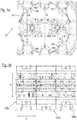
- FIGS. 1a and 1b first show in front view a progressive composite tool system according to the invention, which is generally designated by reference number 10.
- the system 10 in turn comprises a machine platform which comprises three pairs 14, 16 and 18 of attachment positions 14a and 14b, 16a and 16b and 18a and 18b on a machine plate 12 in a circular configuration.
- the progressive tool system 10 in Figure 1a shown in a disarmed state, in which no tool modules are provided at the individual mounting positions 14a to 18b, and in FIG Figure 1b in an equipped state in which the three pairs of mounting positions 14, 16 and 18 are each assigned a tool module 100a, 100b and 100c, which are each mounted with their plungers 102a to 102c at the upper and lower attachment points.
- the distances between the individual pairs of attachment points 14, 16 and 18 are in each case the same, so that the tool modules 100a to 100c can be of the same width, in particular 250 mm, in addition by comparing them by providing a thicker plunger 102b the plungers 102a and 102c compensate for the difference in vertical distance between the middle pair 16 of attachment points and the outer pairs 14 and 18 of attachment points, respectively, so that the inner height h of each of the tool modules 100a to 100c as well as that Width b of the tool modules is identical.
- This is modularization of the tool modules 100a to 100c, which was not yet provided in previously known generic progressive tool systems and apparently enables a simplified exchange for easier setup of the system 10.
- Figure 1c are now in an enlarged view the tool modules 100a to 100c from the Figure 1b shown again.
- these comprise respective upper and lower plungers 102a to 102c, the upper and lower plungers each having an identical structure in the embodiment shown here.
- the plungers 102a to 102c are also constructed in such a way that they have a counter-recess which is complementary to the design of the receiving points 14a to 18b, so that the individual tool modules 100a to 100c can be set up by sliding them from the front into the intended position of the corresponding tool module can take place.
- the fact that the tool modules 100a to 100c can be individually placed and removed in this way enables simplified setting up and dismantling of relatively small operating units, namely the individual tool modules 100a to 100c.
- the tool modules 100a to 100c are basically constructed in the same way apart from the different design of their plungers 102a to 102c, only the right tool module 100a is described below by way of example.
- the upper and lower plungers 102a are adjoined by upper and lower stamp holding regions 104a and 104b, which comprise a holding plate and a pressure plate, by means of which a plurality of stamp holding claws 106 are fixed and positioned. These holding claws 106 are described below in connection with the Figure 2 be described again in more detail.
- Forming modules 108 are in turn carried on the holding claws 106 and are further guided by a stamp guide area 110.
- stamp guide area 110 By assembling the tool modules with regard to their inner height h and their width b, both the stamp holding regions 104 and the stamp guide regions 110 of all tool modules 100a, 100b and 100c can be of the same design.
- the processing plane runs on the central axis in the horizontal direction, in which the individual forming modules 108 process, for example punch and bend, a strip to be processed, which is fed from a strip guide (not shown) according to the progressive bond principle.
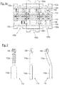
- FIG. 2 some of the forming modules are now shown as examples, which can be provided in the respective tool modules 100a to 100c and in the Figures 1a to 1c can correspond to the tool modules 108.
- a forming module 112 for holding down is shown, by means of which the material to be processed can be clamped.
- a linearly oriented bending module 114 is shown, while on the right a staggered bending module 116 is shown.
- the three forming modules 112, 114 and 116 are each constructed in such a way that they comprise a coupling rod 112a, 114a and 116a, which can be attached to an interface of a corresponding punch-holding claw 106 of one of the tool modules 100a to 100c.
- These interfaces and the corresponding counter-elements of the coupling rods 112a, 114a and 116a each form a hinge joint, so that, in particular in the case of the right bending module 116, the coupling rod 116a can be inclined.
- interfaces are again provided on the coupling rods 112a, 114a and 116a, via which the respective active tool parts 112b, 114b and 116b of the forming modules 112, 114 and 116 are then coupled to the coupling rods 112a, 114a and 116a, whereby also here, the formation of this coupling as a hinge joint allows the tool active part 116b to be aligned vertically, despite the inclined position of the coupling rod 116a.
Landscapes
- Engineering & Computer Science (AREA)
- Mechanical Engineering (AREA)
- Press Drives And Press Lines (AREA)
- Mounting, Exchange, And Manufacturing Of Dies (AREA)
- Perforating, Stamping-Out Or Severing By Means Other Than Cutting (AREA)
Applications Claiming Priority (1)
| Application Number | Priority Date | Filing Date | Title |
|---|---|---|---|
| DE102018217209.9A DE102018217209A1 (de) | 2018-10-09 | 2018-10-09 | Werkzeugmodul für eine Folgeverbund-Werkzeuganlage |
Publications (2)
| Publication Number | Publication Date |
|---|---|
| EP3636363A2 true EP3636363A2 (fr) | 2020-04-15 |
| EP3636363A3 EP3636363A3 (fr) | 2020-05-06 |
Family
ID=67875298
Family Applications (1)
| Application Number | Title | Priority Date | Filing Date |
|---|---|---|---|
| EP19195830.5A Withdrawn EP3636363A3 (fr) | 2018-10-09 | 2019-09-06 | Module d'outil pour une installation d'outil à suivre |
Country Status (2)
| Country | Link |
|---|---|
| EP (1) | EP3636363A3 (fr) |
| DE (1) | DE102018217209A1 (fr) |
Families Citing this family (1)
| Publication number | Priority date | Publication date | Assignee | Title |
|---|---|---|---|---|
| DE102019215750A1 (de) * | 2019-10-14 | 2021-04-15 | Otto Bihler Maschinenfabrik Gmbh & Co. Kg | Einstellbare Koppel für Werkzeuge der Stanz- und Umformtechnik |
Family Cites Families (8)
| Publication number | Priority date | Publication date | Assignee | Title |
|---|---|---|---|---|
| US1527364A (en) * | 1923-11-02 | 1925-02-24 | Kinzel John | Die mechanism for making reamers |
| DE4103302A1 (de) * | 1990-02-05 | 1991-10-17 | Heinz Finzer | Modular aufgebautes werkstueck-bearbeitungszentrum und dazugehoeriger antriebsmodul |
| DE4021346C1 (fr) * | 1990-07-05 | 1991-07-04 | Alpha Maschinenbau Ag, Zuerich, Ch | |
| DE102005045727B4 (de) * | 2005-09-23 | 2009-02-05 | Benteler Automobiltechnik Gmbh | Tiefziehverfahren und Tiefziehmaschine |
| DE102011077308A1 (de) * | 2011-06-09 | 2012-12-13 | Otto Bihler Handels-Beteiligungs-Gmbh | Biegemaschine und Biegewerkzeug |
| DE102013225396A1 (de) * | 2013-12-10 | 2015-06-11 | Bayerische Motoren Werke Aktiengesellschaft | Elektrische Maschine mit optimierter Permanentmagnetverteilung |
| US9908171B2 (en) * | 2015-11-25 | 2018-03-06 | Btm Company Llc | Linkage press machine |
| DE102016204572A1 (de) * | 2016-03-18 | 2017-09-21 | Otto Bihler Handels-Beteiligungs-Gmbh | Umformmaschine und Verfahren zur Positionskorrektur des Schlittenaggregates einer solchen Umformmaschine |
-
2018
- 2018-10-09 DE DE102018217209.9A patent/DE102018217209A1/de not_active Withdrawn
-
2019
- 2019-09-06 EP EP19195830.5A patent/EP3636363A3/fr not_active Withdrawn
Also Published As
| Publication number | Publication date |
|---|---|
| DE102018217209A1 (de) | 2020-04-09 |
| EP3636363A3 (fr) | 2020-05-06 |
Similar Documents
| Publication | Publication Date | Title |
|---|---|---|
| EP3271209B1 (fr) | Dispositif de réglage longitudinal pour un siège de véhicule | |
| EP2860085A1 (fr) | Châssis auxiliaire pour un véhicule automobile | |
| DE102012206288A1 (de) | Verkleidung einer Innenseite einer Seitenwand eines Schienenfahrzeugs | |
| WO2014001373A1 (fr) | Dispositif et procédé destinés à fixer et orienter un rail de guidage | |
| DE202011108083U1 (de) | Vorrichtung mit zumindest einer Einrichtung zum Einstellen eines Führungsspiels | |
| DE2828477A1 (de) | Konsole fuer einen fahrzeugsitz | |
| EP3636363A2 (fr) | Module d'outil pour une installation d'outil à suivre | |
| DE102013209111B4 (de) | Einspannvorrichtung, insbesondere zur Aufnahme und zum Einspannen eines Bauteils, sowie Einspannsystem mit einer solchen Einspannvorrichtung | |
| EP1043116B1 (fr) | Dispositif de serrage pour composants | |
| DE102016200905A1 (de) | Kraftstoffhochdruckpumpe | |
| DE202018006268U1 (de) | Werkzeugmodul für eine Folgeverbund-Werkzeuganlage | |
| WO2020193088A1 (fr) | Système d'entraînement variable | |
| DE102010038814A1 (de) | Metallstruktur einer Rückenlehne eines Kraftfahrzeugsitzes | |
| DE102021129867A1 (de) | Montagegestellvorrichtung zur herstellung von fahrzeugsitzen | |
| DE202020004636U1 (de) | Gehäuse sowie ein Zuschnitt zur Herstellung eines derartigen Gehäuses | |
| AT523965B1 (de) | Biegevorrichtung mit Durchbiegungsausgleich | |
| DE102018124850A1 (de) | Förderstrang für einen Förderer | |
| DE102009003910A1 (de) | Tragschiene für eine Vorrichtung zur Halterung von Wandplatten an einer Wand sowie Fassadenbekleidung | |
| DE102004027140A1 (de) | Mastbaugruppe eines Gabelstaplers und Verfahren zum Herstellen derselben | |
| EP3344478A1 (fr) | Support d'appui | |
| EP3300994A1 (fr) | Système d'amortissement | |
| DE4424877B4 (de) | Vorrichtung zum twistfreien Zusammenbau von Elektronenstrahlsystemen | |
| EP3350054B1 (fr) | Dispositif de ressort destine a la reception de forces transversales et vehicules sur rails comprenant un dispositif de ressort | |
| DE102024134117A1 (de) | Zusammensteckbares Bewehrungselement für einen Bewehrungskorb | |
| EP3067447B1 (fr) | Lisse de préférence destinée au traitement de matériau de chaîne en bandes et procédé de fabrication d'une lisse |
Legal Events
| Date | Code | Title | Description |
|---|---|---|---|
| PUAI | Public reference made under article 153(3) epc to a published international application that has entered the european phase |
Free format text: ORIGINAL CODE: 0009012 |
|
| STAA | Information on the status of an ep patent application or granted ep patent |
Free format text: STATUS: THE APPLICATION HAS BEEN PUBLISHED |
|
| PUAL | Search report despatched |
Free format text: ORIGINAL CODE: 0009013 |
|
| AK | Designated contracting states |
Kind code of ref document: A2 Designated state(s): AL AT BE BG CH CY CZ DE DK EE ES FI FR GB GR HR HU IE IS IT LI LT LU LV MC MK MT NL NO PL PT RO RS SE SI SK SM TR |
|
| AX | Request for extension of the european patent |
Extension state: BA ME |
|
| AK | Designated contracting states |
Kind code of ref document: A3 Designated state(s): AL AT BE BG CH CY CZ DE DK EE ES FI FR GB GR HR HU IE IS IT LI LT LU LV MC MK MT NL NO PL PT RO RS SE SI SK SM TR |
|
| AX | Request for extension of the european patent |
Extension state: BA ME |
|
| RIC1 | Information provided on ipc code assigned before grant |
Ipc: B21D 37/08 20060101ALI20200328BHEP Ipc: B21D 37/04 20060101AFI20200328BHEP Ipc: B21D 37/12 20060101ALI20200328BHEP Ipc: B21F 1/00 20060101ALI20200328BHEP |
|
| 18D | Application deemed to be withdrawn |
Effective date: 20201107 |