EP3636372A1 - Lame de scie à ruban - Google Patents
Lame de scie à ruban Download PDFInfo
- Publication number
- EP3636372A1 EP3636372A1 EP19200389.5A EP19200389A EP3636372A1 EP 3636372 A1 EP3636372 A1 EP 3636372A1 EP 19200389 A EP19200389 A EP 19200389A EP 3636372 A1 EP3636372 A1 EP 3636372A1
- Authority
- EP
- European Patent Office
- Prior art keywords
- tooth
- tip
- teeth
- band saw
- saw blade
- Prior art date
- Legal status (The legal status is an assumption and is not a legal conclusion. Google has not performed a legal analysis and makes no representation as to the accuracy of the status listed.)
- Withdrawn
Links
Images
Classifications
-
- B—PERFORMING OPERATIONS; TRANSPORTING
- B23—MACHINE TOOLS; METAL-WORKING NOT OTHERWISE PROVIDED FOR
- B23D—PLANING; SLOTTING; SHEARING; BROACHING; SAWING; FILING; SCRAPING; LIKE OPERATIONS FOR WORKING METAL BY REMOVING MATERIAL, NOT OTHERWISE PROVIDED FOR
- B23D61/00—Tools for sawing machines or sawing devices; Clamping devices for these tools
- B23D61/02—Circular saw blades
- B23D61/021—Types of set; Variable teeth, e.g. variable in height or gullet depth; Varying pitch; Details of gullet
-
- B—PERFORMING OPERATIONS; TRANSPORTING
- B23—MACHINE TOOLS; METAL-WORKING NOT OTHERWISE PROVIDED FOR
- B23D—PLANING; SLOTTING; SHEARING; BROACHING; SAWING; FILING; SCRAPING; LIKE OPERATIONS FOR WORKING METAL BY REMOVING MATERIAL, NOT OTHERWISE PROVIDED FOR
- B23D61/00—Tools for sawing machines or sawing devices; Clamping devices for these tools
- B23D61/02—Circular saw blades
- B23D61/021—Types of set; Variable teeth, e.g. variable in height or gullet depth; Varying pitch; Details of gullet
- B23D61/0214—Varying tooth height
-
- B—PERFORMING OPERATIONS; TRANSPORTING
- B23—MACHINE TOOLS; METAL-WORKING NOT OTHERWISE PROVIDED FOR
- B23D—PLANING; SLOTTING; SHEARING; BROACHING; SAWING; FILING; SCRAPING; LIKE OPERATIONS FOR WORKING METAL BY REMOVING MATERIAL, NOT OTHERWISE PROVIDED FOR
- B23D61/00—Tools for sawing machines or sawing devices; Clamping devices for these tools
- B23D61/12—Straight saw blades; Strap saw blades
- B23D61/122—Straight saw blades; Strap saw blades with inserted segments having more than one tooth
-
- B—PERFORMING OPERATIONS; TRANSPORTING
- B23—MACHINE TOOLS; METAL-WORKING NOT OTHERWISE PROVIDED FOR
- B23D—PLANING; SLOTTING; SHEARING; BROACHING; SAWING; FILING; SCRAPING; LIKE OPERATIONS FOR WORKING METAL BY REMOVING MATERIAL, NOT OTHERWISE PROVIDED FOR
- B23D61/00—Tools for sawing machines or sawing devices; Clamping devices for these tools
- B23D61/12—Straight saw blades; Strap saw blades
- B23D61/123—Details of saw blade body
- B23D61/125—Composite body, e.g. laminated
-
- B—PERFORMING OPERATIONS; TRANSPORTING
- B27—WORKING OR PRESERVING WOOD OR SIMILAR MATERIAL; NAILING OR STAPLING MACHINES IN GENERAL
- B27B—SAWS FOR WOOD OR SIMILAR MATERIAL; COMPONENTS OR ACCESSORIES THEREFOR
- B27B33/00—Sawing tools for saw mills, sawing machines, or sawing devices
- B27B33/02—Structural design of saw blades or saw teeth
- B27B33/06—Band saw blades
-
- B—PERFORMING OPERATIONS; TRANSPORTING
- B28—WORKING CEMENT, CLAY, OR STONE
- B28D—WORKING STONE OR STONE-LIKE MATERIALS
- B28D1/00—Working stone or stone-like materials, e.g. brick, concrete or glass, not provided for elsewhere; Machines, devices, tools therefor
- B28D1/02—Working stone or stone-like materials, e.g. brick, concrete or glass, not provided for elsewhere; Machines, devices, tools therefor by sawing
- B28D1/08—Working stone or stone-like materials, e.g. brick, concrete or glass, not provided for elsewhere; Machines, devices, tools therefor by sawing with saw-blades of endless cutter-type, e.g. chain saws, i.e. saw chains, strap saws
- B28D1/086—Working stone or stone-like materials, e.g. brick, concrete or glass, not provided for elsewhere; Machines, devices, tools therefor by sawing with saw-blades of endless cutter-type, e.g. chain saws, i.e. saw chains, strap saws consisting of strap saws
-
- Y—GENERAL TAGGING OF NEW TECHNOLOGICAL DEVELOPMENTS; GENERAL TAGGING OF CROSS-SECTIONAL TECHNOLOGIES SPANNING OVER SEVERAL SECTIONS OF THE IPC; TECHNICAL SUBJECTS COVERED BY FORMER USPC CROSS-REFERENCE ART COLLECTIONS [XRACs] AND DIGESTS
- Y10—TECHNICAL SUBJECTS COVERED BY FORMER USPC
- Y10T—TECHNICAL SUBJECTS COVERED BY FORMER US CLASSIFICATION
- Y10T83/00—Cutting
- Y10T83/929—Tool or tool with support
- Y10T83/9319—Toothed blade or tooth therefor
- Y10T83/935—Plural tooth groups
Definitions
- the present invention relates to the field of machine tools and especially band saw blades sawing isolation material such as mineral wool.
- the document EP 1333964 (B27B1/00) is disclosing a wood cutting band saw blade with a tooth form configured to reduce saw dust passing the walls of the blade.
- a tooth of the saw blade has a tip and a shelf tip.
- the shelf tip is configured to function to collect saw dust generated during cutting of a kerf in a work piece.
- Such a previously known saw blade for cutting wood is not suitable for use when sawing isolation material since the dust generation when cutting isolation material would anyhow be to a great disadvantage. Using such a wood cutting blade for cutting isolation material would rip the isolation material apart and the accuracy of the cut is being lost.
- One object of the present invention is to provide a band saw blade having a configuration suitable for cutting isolation material such as mineral wool.
- a further object is to provide a band saw blade which is more resistant to wear than previous known band saw blades when sawing isolation material, particularly of the mineral wool type.
- An object is also to provide for a longer common tooth base in the working direction further increasing the wear out time of the blade.
- the invention relates to a band saw blade having a continuous band portion with a back side and a toothed side designed for a working direction of the blade.
- the blade is designed for sawing isolation material of mineral wool.
- the blade having at its toothed side teeth in which each tooth having a toothface and a toothback with respective angles ⁇ and ⁇ both less than 90°, preferably less than 45° and most preferably less than 30°. These angles provides for a working direction for each tooth. Tooth gullets are located between each tooth.
- Each tooth is provided with a double tip of which one tip is a leading tip and of which the other is a trailing tip and between which tips of the double tip of each tooth there is a tip gullet.
- Each double tip of a specific tooth has the same perpendicular distance from its tip gullet.
- a base of the leading tip and a base of the trailing tip of each tooth is connected to each other at the tip gullet by a material bridge having the same hardened tooth material as the tips and which material bridge is connected to the common base of the tooth by a weld.
- the teeth are arranged in series of groups.
- Each group has a number of teeth arranged in a sequential order and can have either the same tooth height or a sequential deceasing/increasing height of tooth heights. Also a sequential set pattern can be provided for each group.
- the distance that is parallel to the working direction of the blade between the leading tip and the trailing tip of a tooth is the same for all teeth.
- the angle ⁇ is larger than the angle ⁇ . This angle ⁇ provides for a more wear resistant tooth base for a more decreased angle.
- the distance that is parallel to the working direction of the blade between the trailing tip of a leading tooth and the leading tip of a trailing tooth is the same for all teeth.
- the distance that is parallel to the working direction of the blade between the trailing tip of a leading tooth and the leading tip of a trailing tooth decreases from a maximum value for the first tooth gullet of the first tooth to a minimum value for a tooth between the first tooth and the last tooth and increases for the remaining teeth to the second maximum value for the last tooth in each group of teeth.
- the tip gullet depth of a single tooth measured as a perpendicular distance in relation to the working direction of the single tooth is the same for all teeth.
- the set angle of each tooth is 4-10°, preferably 8°.
- the twist angle of each tooth is 0-8°, preferably 6°.
- the tooth gullet depth measured as a perpendicular distance in relation to the working direction of the single tooth is the same for all teeth.
- the tooth gullet depth measured as a perpendicular distance in relation to the working direction of the single tooth decreases from a maximum value for the first tooth gullet of the first tooth to a minimum value for a tooth between the first tooth and the last tooth and increases for the remaining teeth to the second maximum value for the last tooth in each group of teeth.
- each group of teeth has a set pattern of the first tooth being unset and the following teeth is alternating set to right and left with the first set tooth in each group set in either of the two directions.
- the material of the each tip base is connected to each other in that the tooth base at the tip gullet consist of a contiguous part of the tooth material.
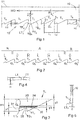
- Figure 1 shows a part of a band saw blade 10 having a back side 11 and a toothed side 12.
- the working direction WD is indicated in the figure with an arrow directed to the left.
- the disclosed embodiment has a straight line back side, however in other embodiments other geometries of the back side is possible, such as different forms of wavy backs also in combination with straight line back sections.
- the blade having at its toothed side 12, teeth T 1 -T n , of which a group T 1 -T 5 are disclosed in the figure.
- Each tooth T n having a toothface TF 1 -TF n and a toothback TB 1 -TB n with angles ⁇ of a toothface TF n and ⁇ of a toothback TB n and in that the angle ⁇ is the angle between the toothface TF n and a line perpendicular to the working direction WD of the blade and in that the angle ⁇ is the angle between the toothback TB n and the working direction WD of the blade.
- ⁇ > ⁇ giving the tooth T 2 a longer base at its toothback TB 2 . This increases the wear resistant of the tooth.
- Each tooth T n is provided with a double tip of which one tip is a leading tip LT n and of which the other is a trailing tip TT n and between which tips of the double tip of each tooth there is a tip gullet TG n .
- the angles of the toothface and toothback of the respective tips are the same as the angles of the tooth described above.
- Each tooth is separated from the closest adjacent tooth by a tooth gullet G n which gullet has a circular bottom with the radius R 1 .
- the tip gullet TG n between the leading tip LT n and the trailing tip TT n has a circular bottom with the radius R 2 .
- the tooth gullet depth H1 between the top edges of the tips and the tooth gullet which in the disclosed embodiment is constant, i.e. the tooth gullet depth H1 is the same for all teeth and measured as a perpendicular distance in relation to the working direction WD of the blade.
- the tip gullet depth H2 between the top edges of the tips in the same tooth and the tip gullet of the tooth is in the disclosed embodiment constant, i.e. the tip gullet depth H2 is the same for all teeth and measured as a perpendicular distance in relation to the working direction WD of the blade.
- L 1 indicates the distance parallel to the working direction WD of the blade 10 between the trailing tip TT n of a leading tooth T n and the leading tip LT n+1 of a trailing tooth T n+1 .
- L 1 is the same for all teeth T 1 -T n .
- L 2 indicates the distance that is parallel to the working direction WD of the blade 10 between the leading tip LT n and the trailing tip TT n of a tooth T n .
- L 2 is the same for all teeth T 1 -T n .
- the following measure proportions appear as indicated in the following table in which the maximum difference between adjacent teeth is 0.08mm and the maximum difference between the highest and the lowest tooth within any 200mm section is 0.10mm: Gullet L 1 ⁇ 0.05 L 2 ⁇ 0.05 H1 ⁇ 0.05 H2 ⁇ 0.05 R 1 ⁇ 0.100 R 2 ⁇ 0.100 ⁇ ⁇ 1° ⁇ ⁇ 1.0° 1 6.50 2 3.14 0.84 0.8 0.4 10 28
- Figure 2 discloses a first group setting sequence of five teeth T 1 -T 5 each having the shape as described under figure 1 . Each group is repeated in series making the groups A-N a complete band of a band saw blade. The figure discloses the settings for group A as follows: Tooth no. T 1 T 2 T 3 T 4 T 5 Setting Unset Right set Left set Right set Left set
- each tooth in the group there is a gullet G 1 -G 5 having the same tooth gullet depth for all teeth of the whole blade in this disclosed embodiment.
- Figure 3 discloses a single tooth T n of a band saw blade according to the invention.
- the tooth having the leading tip LT n and the trailing tip TT n and between which tips the tip gullet TG n is located as previously described.
- a tip base 31 of the leading tip LT n and a tip base 32 of the trailing tip TT n of each tooth T n is connected to each other at the tip gullet TG n by a material bridge 35.
- Both tips are attached to a common base 33 of the tooth T n by a weld 34.
- Both tips are of a hardened material which is attached by a welding operation to the common base part which is of a softer material in order to resist continuous bending of the blade under motion.
- the material bridge 35 is having the same hardened tooth material as the tips and which material bridge 35 is thus connected to the common base 33.
- the figure also indicates the height y1 of the tip including its tip base 31.
- the height y1 has the measure interval of 0.5 - 1.0 mm, preferably of 0.6 - 0.9 mm and most preferably 0.7 - 0.8 mm.
- Figure 4 discloses the set twist angle ⁇ of the leading tip LT n and the trailing tip TT n which is between 0° and 8°, preferably 4-6°. This twist angle is the same for both tips of the tooth however the direction of the twist is dependent upon the setting.
- Figure 5 discloses the setting angle ⁇ of each tooth which angle is between 4° and 10°, preferably 8°. In the figure only one setting direction of one tooth T n with its leading tip LT n is indicated. The section in the figure is taken through the blade 10.
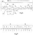
- Figure 6 discloses a part of a band saw blade 60 according to a second embodiment of the invention.
- a sequence part of five teeth T 1 -T 5 is disclosed, in that the first tooth T 1 is the highest tooth with the tooth gullet depth H1 1 decreasing its tooth gullet depth value up to the fifth tooth T 5 which is the shortest tooth with the tooth gullet depth H1 5 .
- each distance L2 that is parallel to the working direction WD of the blade 60 between the leading tip LT 1 and the trailing tip TT 1 of a tooth T 1 is equal for all teeth.
- the distance L1 between the leading tip LT1 of a tooth T1 and the leading tip LT2 of the tooth T2 behind is decreasing for each tooth in the disclosed sequence.
- the sequence contains seven teeth arranged with a decreasing value H1 for the consecutive five first teeth T 1 -T 5 and with an increasing value H1 for the last two teeth T 6 -T 7 wherein the gullet for the first tooth is notated G 1 and the gullet for the second tooth is notated G 2 and the gullet for the fifth tooth is notated G 5 .
- the rest of the measures of this second embodiment have the same notations as the blade disclosed in figures 1 and 2 of the first embodiment.
- a band saw blade according to this second embodiment can have the following measures: Gullet X1 ⁇ 0.05 L2 ⁇ 0.05 H1 ⁇ 0.05 H2 ⁇ 0.05 R 1 ⁇ 0.100 R 2 ⁇ 0.100 ⁇ ⁇ 1° ⁇ ⁇ 1.0° 1 5.86 1.5 2.05 0.54 0.6 0.4 10 28 2 5.56 1.5 1.87 0.54 0.6 0.4 10 28 3 5.03 1.5 1.35 0.54 0.6 0.4 10 28 4 4.54 1.5 1.28 0.54 0.6 0.4 10 28 5 4.33 1.5 1.15 0.54 0.6 0.4 10 28 6 4.79 1.5 1.42 0.54 0.6 0.4 10 28 7 5.25 1.5 1.69 0.54 0.6 0.4 10 28 ⁇ 35.36 Consequently the group length in this second embodiment is 35.36 mm.
- Figure 7 illustrates a group setting for two consecutive appearing groups A, B of a blade according to the second embodiment of the invention where each group has seven teeth. This sequence of grouping continues for the whole blade.
- the setting for one group A is as follows: Tooth T 1 T 2 T 3 T 4 T 5 T 6 T 7 Setting Unset Right set Left set Right set Left set Right set Left set
- the described two embodiments describe two different types of band saw blades each having its advantages depending of the material to be cut and at which band velocity the cutting is taken place.
Landscapes
- Engineering & Computer Science (AREA)
- Mechanical Engineering (AREA)
- Mining & Mineral Resources (AREA)
- Life Sciences & Earth Sciences (AREA)
- Wood Science & Technology (AREA)
- Forests & Forestry (AREA)
- Sawing (AREA)
- Harvester Elements (AREA)
Applications Claiming Priority (1)
| Application Number | Priority Date | Filing Date | Title |
|---|---|---|---|
| SE1851230A SE542651C2 (en) | 2018-10-09 | 2018-10-09 | Band saw blade |
Publications (1)
| Publication Number | Publication Date |
|---|---|
| EP3636372A1 true EP3636372A1 (fr) | 2020-04-15 |
Family
ID=68104415
Family Applications (1)
| Application Number | Title | Priority Date | Filing Date |
|---|---|---|---|
| EP19200389.5A Withdrawn EP3636372A1 (fr) | 2018-10-09 | 2019-09-30 | Lame de scie à ruban |
Country Status (3)
| Country | Link |
|---|---|
| EP (1) | EP3636372A1 (fr) |
| RU (1) | RU2019131697A (fr) |
| SE (1) | SE542651C2 (fr) |
Citations (3)
| Publication number | Priority date | Publication date | Assignee | Title |
|---|---|---|---|---|
| EP1333964A2 (fr) | 2000-10-25 | 2003-08-13 | AMERICAN SAW & MFG. COMPANY | Lame de scie a ruban pour la decoupe du bois |
| JP2003340644A (ja) * | 2002-05-29 | 2003-12-02 | Amada Co Ltd | バイメタル帯鋸刃 |
| JP2003340642A (ja) * | 2002-05-22 | 2003-12-02 | Amada Co Ltd | 鋸 刃 |
-
2018
- 2018-10-09 SE SE1851230A patent/SE542651C2/en unknown
-
2019
- 2019-09-30 EP EP19200389.5A patent/EP3636372A1/fr not_active Withdrawn
- 2019-10-08 RU RU2019131697A patent/RU2019131697A/ru unknown
Patent Citations (3)
| Publication number | Priority date | Publication date | Assignee | Title |
|---|---|---|---|---|
| EP1333964A2 (fr) | 2000-10-25 | 2003-08-13 | AMERICAN SAW & MFG. COMPANY | Lame de scie a ruban pour la decoupe du bois |
| JP2003340642A (ja) * | 2002-05-22 | 2003-12-02 | Amada Co Ltd | 鋸 刃 |
| JP2003340644A (ja) * | 2002-05-29 | 2003-12-02 | Amada Co Ltd | バイメタル帯鋸刃 |
Also Published As
| Publication number | Publication date |
|---|---|
| SE1851230A1 (en) | 2020-04-10 |
| SE542651C2 (en) | 2020-06-23 |
| RU2019131697A (ru) | 2021-04-08 |
Similar Documents
| Publication | Publication Date | Title |
|---|---|---|
| JP4447665B2 (ja) | 改良された帯鋸 | |
| EP1237674B1 (fr) | Lame de scie a ruban a bruit reduit et a charge de dents uniforme | |
| EP2602042B1 (fr) | Lame de scie avec projection de forme de dent | |
| US20040255749A1 (en) | Bandsaw blade and cutter tooth arrangement therefor | |
| JP2002505626A5 (fr) | ||
| GB2113144A (en) | Saw blade | |
| US20070251372A1 (en) | Enhanced performance saw blade toothform pattern | |
| JP2013533811A (ja) | 苛酷な切断用途用鋸刃の歯形 | |
| US20050257660A1 (en) | Bandsaw blade and method of manufacturing a bandsaw blade | |
| CA2845468C (fr) | Lame de scie avec limiteur d'alimentation | |
| MX2010009554A (es) | Escariador helicoidal para desbaste. | |
| EP4101611B1 (fr) | Lame de scie | |
| US2880768A (en) | Hard metal tipped saw | |
| CN100415426C (zh) | 刺锯片 | |
| JP2007307911A (ja) | 硬質層を持つ鋸歯 | |
| RU2305626C1 (ru) | Ленточная пила | |
| SE542651C2 (en) | Band saw blade | |
| EP1586401A1 (fr) | Lame de scie à ruban et procédé de fabrication d'une lame de scie à ruban | |
| CN213702036U (zh) | 一种硬质合金锯片 | |
| EP2866983B1 (fr) | Lame de couteau à pain et son procédé de fabrication | |
| CN213646141U (zh) | 一种组配小齿型的双金属锯条 | |
| EP1470884B1 (fr) | Lame de scie à ruban | |
| EP3321019B1 (fr) | Lame de scie à ruban | |
| US461509A (en) | Art of manufacturing saws | |
| RO121804B1 (ro) | Freză cilindrică, cu alezaj, pentru cant drept şi pentru profil lat |
Legal Events
| Date | Code | Title | Description |
|---|---|---|---|
| PUAI | Public reference made under article 153(3) epc to a published international application that has entered the european phase |
Free format text: ORIGINAL CODE: 0009012 |
|
| STAA | Information on the status of an ep patent application or granted ep patent |
Free format text: STATUS: THE APPLICATION HAS BEEN PUBLISHED |
|
| AK | Designated contracting states |
Kind code of ref document: A1 Designated state(s): AL AT BE BG CH CY CZ DE DK EE ES FI FR GB GR HR HU IE IS IT LI LT LU LV MC MK MT NL NO PL PT RO RS SE SI SK SM TR |
|
| AX | Request for extension of the european patent |
Extension state: BA ME |
|
| STAA | Information on the status of an ep patent application or granted ep patent |
Free format text: STATUS: REQUEST FOR EXAMINATION WAS MADE |
|
| 17P | Request for examination filed |
Effective date: 20200903 |
|
| RBV | Designated contracting states (corrected) |
Designated state(s): AL AT BE BG CH CY CZ DE DK EE ES FI FR GB GR HR HU IE IS IT LI LT LU LV MC MK MT NL NO PL PT RO RS SE SI SK SM TR |
|
| STAA | Information on the status of an ep patent application or granted ep patent |
Free format text: STATUS: EXAMINATION IS IN PROGRESS |
|
| 17Q | First examination report despatched |
Effective date: 20211014 |
|
| STAA | Information on the status of an ep patent application or granted ep patent |
Free format text: STATUS: THE APPLICATION IS DEEMED TO BE WITHDRAWN |
|
| 18D | Application deemed to be withdrawn |
Effective date: 20220225 |