EP3636373A1 - Procédé et dispositif de vérification d'un serrage de lame à barre et / ou d'un logement de lame d'une tête de lame à barre destinée à la fabrication d'une roue conique - Google Patents
Procédé et dispositif de vérification d'un serrage de lame à barre et / ou d'un logement de lame d'une tête de lame à barre destinée à la fabrication d'une roue conique Download PDFInfo
- Publication number
- EP3636373A1 EP3636373A1 EP19200687.2A EP19200687A EP3636373A1 EP 3636373 A1 EP3636373 A1 EP 3636373A1 EP 19200687 A EP19200687 A EP 19200687A EP 3636373 A1 EP3636373 A1 EP 3636373A1
- Authority
- EP
- European Patent Office
- Prior art keywords
- knife
- component
- bar
- rod
- base body
- Prior art date
- Legal status (The legal status is an assumption and is not a legal conclusion. Google has not performed a legal analysis and makes no representation as to the accuracy of the status listed.)
- Granted
Links
Images


Classifications
-
- B—PERFORMING OPERATIONS; TRANSPORTING
- B23—MACHINE TOOLS; METAL-WORKING NOT OTHERWISE PROVIDED FOR
- B23F—MAKING GEARS OR TOOTHED RACKS
- B23F23/00—Accessories or equipment combined with or arranged in, or specially designed to form part of, gear-cutting machines
- B23F23/12—Other devices, e.g. tool holders; Checking devices for controlling workpieces in machines for manufacturing gear teeth
-
- B—PERFORMING OPERATIONS; TRANSPORTING
- B23—MACHINE TOOLS; METAL-WORKING NOT OTHERWISE PROVIDED FOR
- B23F—MAKING GEARS OR TOOTHED RACKS
- B23F21/00—Tools specially adapted for use in machines for manufacturing gear teeth
- B23F21/12—Milling tools
- B23F21/22—Face-mills for longitudinally-curved gear teeth
- B23F21/223—Face-mills for longitudinally-curved gear teeth with inserted cutting elements
- B23F21/226—Face-mills for longitudinally-curved gear teeth with inserted cutting elements in exchangeable arrangement
-
- B—PERFORMING OPERATIONS; TRANSPORTING
- B23—MACHINE TOOLS; METAL-WORKING NOT OTHERWISE PROVIDED FOR
- B23F—MAKING GEARS OR TOOTHED RACKS
- B23F23/00—Accessories or equipment combined with or arranged in, or specially designed to form part of, gear-cutting machines
- B23F23/12—Other devices, e.g. tool holders; Checking devices for controlling workpieces in machines for manufacturing gear teeth
- B23F23/1218—Checking devices for controlling workpieces in machines for manufacturing gear teeth
-
- B—PERFORMING OPERATIONS; TRANSPORTING
- B23—MACHINE TOOLS; METAL-WORKING NOT OTHERWISE PROVIDED FOR
- B23F—MAKING GEARS OR TOOTHED RACKS
- B23F21/00—Tools specially adapted for use in machines for manufacturing gear teeth
-
- B—PERFORMING OPERATIONS; TRANSPORTING
- B23—MACHINE TOOLS; METAL-WORKING NOT OTHERWISE PROVIDED FOR
- B23F—MAKING GEARS OR TOOTHED RACKS
- B23F9/00—Making gears having teeth curved in their longitudinal direction
- B23F9/08—Making gears having teeth curved in their longitudinal direction by milling, e.g. with helicoidal hob
- B23F9/10—Making gears having teeth curved in their longitudinal direction by milling, e.g. with helicoidal hob with a face-mill
-
- B—PERFORMING OPERATIONS; TRANSPORTING
- B23—MACHINE TOOLS; METAL-WORKING NOT OTHERWISE PROVIDED FOR
- B23Q—DETAILS, COMPONENTS, OR ACCESSORIES FOR MACHINE TOOLS, e.g. ARRANGEMENTS FOR COPYING OR CONTROLLING; MACHINE TOOLS IN GENERAL CHARACTERISED BY THE CONSTRUCTION OF PARTICULAR DETAILS OR COMPONENTS; COMBINATIONS OR ASSOCIATIONS OF METAL-WORKING MACHINES, NOT DIRECTED TO A PARTICULAR RESULT
- B23Q17/00—Arrangements for observing, indicating or measuring on machine tools
- B23Q17/002—Arrangements for observing, indicating or measuring on machine tools for indicating or measuring the holding action of work or tool holders
-
- B—PERFORMING OPERATIONS; TRANSPORTING
- B23—MACHINE TOOLS; METAL-WORKING NOT OTHERWISE PROVIDED FOR
- B23Q—DETAILS, COMPONENTS, OR ACCESSORIES FOR MACHINE TOOLS, e.g. ARRANGEMENTS FOR COPYING OR CONTROLLING; MACHINE TOOLS IN GENERAL CHARACTERISED BY THE CONSTRUCTION OF PARTICULAR DETAILS OR COMPONENTS; COMBINATIONS OR ASSOCIATIONS OF METAL-WORKING MACHINES, NOT DIRECTED TO A PARTICULAR RESULT
- B23Q17/00—Arrangements for observing, indicating or measuring on machine tools
- B23Q17/09—Arrangements for observing, indicating or measuring on machine tools for indicating or measuring cutting pressure or for determining cutting-tool condition, e.g. cutting ability, load on tool
- B23Q17/0904—Arrangements for observing, indicating or measuring on machine tools for indicating or measuring cutting pressure or for determining cutting-tool condition, e.g. cutting ability, load on tool before or after machining
- B23Q17/0919—Arrangements for measuring or adjusting cutting-tool geometry in presetting devices
-
- B—PERFORMING OPERATIONS; TRANSPORTING
- B23—MACHINE TOOLS; METAL-WORKING NOT OTHERWISE PROVIDED FOR
- B23Q—DETAILS, COMPONENTS, OR ACCESSORIES FOR MACHINE TOOLS, e.g. ARRANGEMENTS FOR COPYING OR CONTROLLING; MACHINE TOOLS IN GENERAL CHARACTERISED BY THE CONSTRUCTION OF PARTICULAR DETAILS OR COMPONENTS; COMBINATIONS OR ASSOCIATIONS OF METAL-WORKING MACHINES, NOT DIRECTED TO A PARTICULAR RESULT
- B23Q17/00—Arrangements for observing, indicating or measuring on machine tools
- B23Q17/12—Arrangements for observing, indicating or measuring on machine tools for indicating or measuring vibration
-
- G—PHYSICS
- G05—CONTROLLING; REGULATING
- G05B—CONTROL OR REGULATING SYSTEMS IN GENERAL; FUNCTIONAL ELEMENTS OF SUCH SYSTEMS; MONITORING OR TESTING ARRANGEMENTS FOR SUCH SYSTEMS OR ELEMENTS
- G05B19/00—Program-control systems
- G05B19/02—Program-control systems electric
- G05B19/18—Numerical control [NC], i.e. automatically operating machines, in particular machine tools, e.g. in a manufacturing environment, so as to execute positioning, movement or co-ordinated operations by means of program data in numerical form
- G05B19/406—Numerical control [NC], i.e. automatically operating machines, in particular machine tools, e.g. in a manufacturing environment, so as to execute positioning, movement or co-ordinated operations by means of program data in numerical form characterised by monitoring or safety
-
- G—PHYSICS
- G05—CONTROLLING; REGULATING
- G05B—CONTROL OR REGULATING SYSTEMS IN GENERAL; FUNCTIONAL ELEMENTS OF SUCH SYSTEMS; MONITORING OR TESTING ARRANGEMENTS FOR SUCH SYSTEMS OR ELEMENTS
- G05B19/00—Program-control systems
- G05B19/02—Program-control systems electric
- G05B19/18—Numerical control [NC], i.e. automatically operating machines, in particular machine tools, e.g. in a manufacturing environment, so as to execute positioning, movement or co-ordinated operations by means of program data in numerical form
- G05B19/182—Numerical control [NC], i.e. automatically operating machines, in particular machine tools, e.g. in a manufacturing environment, so as to execute positioning, movement or co-ordinated operations by means of program data in numerical form characterised by the machine tool function, e.g. thread cutting, cam making, tool direction control
- G05B19/186—Generation of screw- or gearlike surfaces
-
- G—PHYSICS
- G05—CONTROLLING; REGULATING
- G05B—CONTROL OR REGULATING SYSTEMS IN GENERAL; FUNCTIONAL ELEMENTS OF SUCH SYSTEMS; MONITORING OR TESTING ARRANGEMENTS FOR SUCH SYSTEMS OR ELEMENTS
- G05B2219/00—Program-control systems
- G05B2219/30—Nc systems
- G05B2219/50—Machine tool, machine tool null till machine tool work handling
- G05B2219/50183—Detect correct clamping of workpiece, chucks grip properly workpiece
Definitions
- the present invention relates to a method and a device for checking a stick knife clamping and / or a knife shaft of a stick knife head for the production of bevel gears.
- Bar cutter heads are used to manufacture bevel gears.
- a rod measuring head usually consists of a basic body with rod knives, the basic body having knife shafts with clamping devices for clamping the rod knives.
- the bar knives are used for machining soft machining with a defined cutting edge and are often provided as coated hard metal bars.
- the bar knives are detachably held on the base body of the knife head and are usually clamped against contact surfaces of the knife shaft in a knife shaft using a movable clamping element of the clamping device.
- the clamping element is moved with one or more screws to narrow the knife shaft for clamping the bar knife. It can be provided that one or more screws clamp a bar knife in direct contact with the bar knife shaft in the knife shaft. It can be provided that so-called parallel plates are arranged between the bar knife and a wall delimiting the knife shaft in order to adjust the radial position of a respective bar knife.
- a break in the bar knife usually makes it unusable for further use.
- the vibrating of the bar knife can lead to ripples, insufficient topography of the tooth flanks and possibly to visible chatter marks on the tooth flanks produced, so that the workpiece may not be suitable for hard fine machining.
- Chip welding in the area of the rake face of a bar knife can cause clogging (chip clogging) of an intermediate space provided between adjacent bar knives, the accumulation of the chips adversely affecting the processing quality and, in turn, can lead to breakage or damage to the bar knife in question.
- the present invention is based on the technical problem of specifying a method and a device for checking a stick knife clamping of a stick knife head.
- the technical problem described above is solved by a method according to claim 1 and an apparatus according to claim 11. Further developments of the invention result from the dependent claims and the description below.
- the invention relates to a method for checking a rod knife clamping and / or a knife shaft of a rod knife head for the production of bevel gears, with the method steps: providing a base body of a rod knife head, the base body having knife shafts for receiving rod knives, and wherein in at least one knife shaft Base body of the rod cutter head, a component such as a rod cutter, a test specimen or the like, is releasably and interchangeably clamped; Vibration excitation of the component; Measuring the displacement and / or speed and / or acceleration of the component; Evaluation of the measurement.
- the method therefore makes it possible to evaluate the clamping of a component, such as a bar knife, a test specimen or the like, in the finished Condition mounted on the base body of the rod cutter head, so that, irrespective of which of the influencing variables mentioned at the outset affects the fit of the component, inadequate clamping of the component in the cutter shaft can be detected.
- a component such as a bar knife, a test specimen or the like
- the bar cutter head can be set up for machining workpiece machining to produce a bevel gear.
- the method enables the fit of a respective bar knife to be checked in the assigned knife shaft.
- the tool system intended for bevel gear production can therefore be checked.
- the production quality and / or the state of wear of the knife shafts of the base body of the rod cutter head can be checked.
- the base body of the cutter head can be checked in particular with the aid of a standardized test body, which can also have a standardized system for a contact element of the measuring system.
- the evaluation shows e.g. For a bar knife clamped on the base body that a measured deflection and / or speed and / or acceleration of the bar knife due to the vibration excitation exceeds a predetermined, maximum permissible deflection and / or speed and / or acceleration, the fit of the bar knife in question is checked. If necessary, the bar knife can be re-clamped, the surfaces of the bar knife and knife shaft that are in contact with each other in the tensioned state can be cleaned, the bar knife and knife shaft measured or other measures taken to identify and eliminate the cause of the insufficient clamping. It is crucial that the insufficient clamping of the bar knife in question can be detected before the cutter head is released for production and possibly causes the problems described in the introduction.
- the method described above can equally be carried out on a rod cutter head that has not achieved the required processing quality in production in order to find out the cause of this and to collect data for identical rod cutter heads or identical cutter head base bodies.
- the method described above can equally be carried out on a rod cutter head which has achieved the required processing quality in production in order to collect reference data for rod rod heads of identical construction or basic cutter head bodies of identical construction.
- the evaluation shows e.g. For a test specimen clamped to the base body that a measured deflection and / or speed and / or acceleration of the test specimen as a result of the vibration excitation exceeds a predetermined, maximum permissible deflection and / or speed and / or acceleration, the knife shaft in which the test specimen sits is checked. Again, e.g. a determination of manufacturing deviations and / or signs of wear and / or cleaning is carried out in order to identify and eliminate the cause of the inadequate clamping. It is crucial that the inadequate quality of the knife shaft in question can be recognized before the knife head is released for production.
- the method carried out above with the aid of the test specimen can likewise be carried out on a rod cutter head which has not achieved the required processing quality in production in order to determine the cause of this.
- the method using the test specimen, carried out above with the aid of the test specimen, can likewise be carried out on a rod cutter head which has achieved the required processing quality in production in order to collect reference data for identical rod cutter heads or identical cutter head base bodies.
- the provision of the base body comprises the following step: placing the base body of the rod cutter head on a horizontally oriented plane.
- the base body to be tested therefore lies flat on a plane level so that the measurement result is not affected by deformation of the base body under its own weight.
- a respective base body of the rod cutter head corresponds to its orientation is recorded on a test set-up within a machine tool in order to represent the installation state on a machine tool as realistically as possible.
- the base body of the rod cutter head or the base body fully equipped with rod blades is checked in the state in which it is assembled on a machine tool using the method according to the invention.
- Individual knife shafts or bar knives are identified as the cause of chatter marks or ripples on the tooth flanks and, if necessary, replaced or their fit improved without removing the knife head or the base body from the machine tool.
- vibration excitation of the base body itself and / or of the individual component can take place.
- the vibration excitation of the component comprises the following steps: pretensioning the component with the aid of a force element which is supported between the component and a stop; Vibration excitation of the component using a vibration exciter.
- the vibration excitation takes place exclusively on the component to be checked, such as a bar knife, a test specimen or the like. If a bar knife is clamped, e.g. a targeted application of force e.g. on the shaft or in the area of the cutting profile of the bar knife to be tested.
- the vibration excitation of the component takes place in the radial direction relative to a longitudinal axis of a cutter head central bore; and / or the vibration excitation of the component, such as a bar knife, a test specimen or the like, takes place in the tangential direction, viewed in relation to a bolt circle spanned by the cavities of the base body.
- the direction of a force application to a component can be radial, tangential or inclined to the radial and tangential direction.
- test of such a seat or of such a voltage can be restricted to this type of test with radial excitation.
- the method according to the invention can thus be adapted to a respective tool system as required, in the present case a rod cutter head being synonymously referred to as a tool system.
- the measurement of the displacement and / or speed and / or acceleration of the component takes place optically, in particular with the aid of a laser.
- the displacement and / or speed and / or acceleration of the component can be detected reliably and precisely as a result of the vibration excitation.
- the component such as a bar knife, a test specimen or the like
- the evaluation of the measurement comprises the following step: determining the dynamic compliance of the component, such as a bar knife, a test specimen or the like, in the form of a frequency response with a force signal of the vibration excitation as an input signal and a component movement as an output signal .
- the displacement of the component due to the force excitation can be described in particular. For example, based on the amount the shift, it is determined whether the clamping of the component is correct or, if a limit value is exceeded, it must be checked.
- a modal analysis can be carried out in order to detect inadequate clamping on the basis of the determined natural frequencies and the associated amplitudes. So e.g., a shift in the natural frequencies can be an indication of inadequate clamping or an unusually strong deflection, speed or acceleration can be detected for a certain frequency.
- the evaluation of the measurement has the following steps: comparison of one or more measurement values of the measurement with a reference value and / or calculation of a key figure from measured values of the measurement and comparison with a reference key figure.
- a system that represents the ideal possible clamping condition of a component, such as a bar knife, a test specimen or the like, in a knife shaft can be used to form a reference as a comparison variable for the bar knife head to be tested or its base body.
- the reference can have been optimized in the base body with regard to all the influencing variables mentioned at the outset on the seating of a component, such as a bar knife, a test specimen or the like, in order to achieve the best possible clamping condition.
- a maximum permissible deviation of the displacement and / or speed and / or acceleration from this reference can then be defined in order to check the clamping of the component of a new rod cutter head to be used in production and / or already used.
- one or more rod knives of a further rod knife head of identical construction or of a plurality of further rod knife heads of identical construction are measured before the evaluation to determine the reference value and / or the reference characteristic number.
- a plurality of rod knives of one or more identical rod knife heads can be used in new condition and at different wear states are measured in order to determine measurement data of bar knife fixtures with a reliable clamping condition and rod knife fixtures which have caused problems during operation. Provision can be made for all measurement data to be collected in a database in order to determine characteristic values for safe and critical clamping states of bar knives in the associated knife shafts.
- test specimen can be measured in an identical basic body of a further rod cutter head or in a plurality of identical basic bodies of the rod cutter head before the evaluation to determine the reference value and / or the reference key figure.
- test specimens can be measured in identical basic bodies in new condition and at different wear conditions in order to determine measurement data of fixtures with a reliable fixation condition and fixtures that have caused problems during operation.
- Provision can be made for all the measurement data to be collected in a database in order to determine characteristic values for safe and critical clamping states.
- the provided base body of the bar cutter head is equipped with two bar cutters in two or more cutter shafts or in all cutter shafts, with the vibration excitation, measurement and evaluation being carried out for each bar cutter.
- a base body that is fully equipped with bar knives can be checked for the correct fit of each bar knife in the assigned knife shaft.
- the individual knives can be checked successively or two or more knives simultaneously with regard to their clamping within the respective knife shaft.
- a knife shaft is used to hold a bar knife, this can be a blind hole provided on the base body or a through opening provided on the base body.
- the invention relates to a device for checking a stick knife clamping and / or a knife shaft of a stick knife head, set up for carrying out the method according to the invention, with a receptacle for arranging the base body of the stick knife head, with a device for vibrating the component; with a measuring device for measuring the displacement and / or speed and / or acceleration of the component.
- the receptacle for arranging the base body of the bar cutter head can be a horizontally oriented plane surface.
- the base body of the rod cutter head can be clamped in accordance with its orientation within a machine tool in order to approximate the operating state.
- the rod cutter head or the base body of the rod cutter head can be checked in the state that has been picked up on a machine tool.
- the device for vibration excitation is set up to excite exactly one component, such as a bar knife, a test specimen or the like.
- two or more components such as bar knives, test specimens or the like
- diametrically arranged components such as bar knives, test specimens or the like
- two or more pairs of diametrically arranged components such as bar knives, test specimens or the like, are tested simultaneously.
- a single, two or more vibration exciters can be used.
- a further embodiment of the device is characterized in that the device for vibration excitation has a stop, a force element, a vibration exciter, a force sensor and a contact element, the contact element being designed to bear against the component, such as a bar knife, a test specimen or the like is and wherein the force element, the vibration exciter and the force sensor are arranged in the assembled state between the stop and the contact element, in particular are arranged coaxially.
- the force element, the vibration exciter and the force sensor are arranged in the assembled state between the stop and the contact element, in particular are arranged coaxially.
- the stop can be received in the fully assembled state in a central cutter head bore of the base body of the rod cutter head in order to achieve a defined, reproducible contact point for supporting the force element and the vibration exciter.
- a further embodiment of the device is characterized by a control and evaluation unit which is set up for the fully automatic implementation and evaluation of the method according to the invention.
- the device is set up for the fully automatic fitting of the base body with rod knives and / or test specimens and for the subsequent fully automatic testing of the fit or the clamping state of each individual rod knife and / or test specimen.
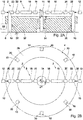
- Fig. 1A shows a device 2 for checking a bar knife clamping of a bar knife head 4.
- the device 2 has a receptacle 6 for arranging a base body 26 of the bar knife head 4.
- the receptacle 6 is formed as a horizontal plane plane 6.
- the device 2 has a device 8 for vibrating a component 10, which is formed here in the form of a bar knife 10.
- the device 2 has a measuring device 12 for measuring the displacement and / or speed and / or acceleration of the bar knife 10.
- the device 8 for vibration excitation has a stop 14, a force element 16, a vibration exciter 18, a force sensor 20 and a contact element 22.
- the contact element 22 lies against the bar knife 10 and is adapted to the cutting profile of the bar knife 10.
- the force element 16, the vibration exciter 18 and the force sensor 20 are in accordance with Fig. 1A shown, fully assembled state lined up between the stop 14 and the contact element 22, arranged coaxially.
- the bar cutter head 4 has cutter shafts 30 in which the bar cutters 10 are releasably and interchangeably clamped to the base body 26.
- the stop 14 is received in a cutter head central bore 24 of a base body 26 of the rod cutter head 4.
- the device 2 also has a control and evaluation unit 28 which is set up for the fully automatic implementation and evaluation of the method described below.
- control and evaluation unit 28 is wirelessly connected to the measuring device 12, the force element 16, the vibration exciter 18 and the force sensor 20. According to alternative exemplary embodiments, it can be provided that the control and evaluation unit 28 is connected to one or more of the aforementioned elements in a wired manner.
- a rod cutter head 4 is first provided and its base body 26 is placed on the horizontal plane 6.
- the rod cutter head 4 is for machining workpiece machining set up for the production of a bevel gear, the bar knives 10 being designed to produce the tooth gaps of a bevel gear to be manufactured.
- the bar knives 10 are detachably and interchangeably held on the base body 26.
- step B the bar knife 10 is vibrated with the aid of the device 8 for vibrating.
- a method step C the displacement and / or the speed and / or the acceleration of the bar knife 10 is recorded using the measuring device 12.
- the evaluation device 28 then evaluates the measurement in a method step D in order to evaluate the quality of the bar knife clamping of the bar knife 10 to be tested.
- the vibration excitation of the bar knife 10 in method step B has the following method steps: prestressing the bar knife 10 with the aid of the force element 16, which is supported between the bar knife 10 and the stop 14; Vibration excitation of the bar knife 10 using the vibration exciter 18.
- the vibration excitation of the bar knife 10 takes place relative to a longitudinal axis of the cutter head central bore 24 oriented along the z-axis, viewed in the radial direction and thus parallel to the y-axis.
- the vibration excitation of the bar knife 10 takes place in a tangential direction relative to a hole circle spanned by the cavities 28 of the base body 26, that is to say, acting on the bar knife 10 parallel to the x-axis.
- the displacement and / or the speed and / or the acceleration of the bar knife 10 is measured optically using a laser 12.
- the evaluation of the measurement in method step D comprises the step: determining the dynamic flexibility of the bar knife 10 in the form of a frequency response, using a force signal measured with the aid of the force sensor 20 the vibration excitation as an input variable and the knife movement detected using the laser 12 as an output variable.
- the bar knife seat having to be checked if the limit value is exceeded, and the bar knife seat or the clamping of the bar knife 10 in the base body 26 if the limit value is undershot is found to be good.
- the bar knife head 4 is equipped with a bar knife 10 in each of the cavities 28, the vibration excitation, measurement and evaluation being carried out successively for each bar knife 10 in accordance with method steps B, C and D.
Landscapes
- Engineering & Computer Science (AREA)
- Mechanical Engineering (AREA)
- Human Computer Interaction (AREA)
- Manufacturing & Machinery (AREA)
- Physics & Mathematics (AREA)
- General Physics & Mathematics (AREA)
- Automation & Control Theory (AREA)
- Investigating Strength Of Materials By Application Of Mechanical Stress (AREA)
- Testing Of Devices, Machine Parts, Or Other Structures Thereof (AREA)
- Testing Of Balance (AREA)
Applications Claiming Priority (1)
| Application Number | Priority Date | Filing Date | Title |
|---|---|---|---|
| DE102018125135.1A DE102018125135A1 (de) | 2018-10-11 | 2018-10-11 | Verfahren und vorrichtung zur kontrolle einer stabmessereinspannung und/oder eines messerschachts eines stabmesserkopfs zur kegelradherstellung |
Publications (2)
| Publication Number | Publication Date |
|---|---|
| EP3636373A1 true EP3636373A1 (fr) | 2020-04-15 |
| EP3636373B1 EP3636373B1 (fr) | 2020-12-23 |
Family
ID=68109153
Family Applications (1)
| Application Number | Title | Priority Date | Filing Date |
|---|---|---|---|
| EP19200687.2A Active EP3636373B1 (fr) | 2018-10-11 | 2019-10-01 | Procédé et dispositif de vérification d'un serrage de lame à barre et / ou d'un logement de lame d'une tête de lame à barre destinée à la fabrication d'une roue conique |
Country Status (4)
| Country | Link |
|---|---|
| US (1) | US20200114442A1 (fr) |
| EP (1) | EP3636373B1 (fr) |
| CN (1) | CN111037007A (fr) |
| DE (1) | DE102018125135A1 (fr) |
Cited By (1)
| Publication number | Priority date | Publication date | Assignee | Title |
|---|---|---|---|---|
| CN113857590A (zh) * | 2021-09-30 | 2021-12-31 | 中国航发南方工业有限公司 | 一种花键加工用插齿刀杆及插齿刀杆加粗方法 |
Families Citing this family (3)
| Publication number | Priority date | Publication date | Assignee | Title |
|---|---|---|---|---|
| EP3954481B1 (fr) * | 2019-04-11 | 2023-09-13 | Citizen Watch Co., Ltd. | Machine-outil et procédé de détection |
| CN115635148B (zh) * | 2022-10-21 | 2023-05-09 | 湖南中大创远数控装备有限公司 | 一种螺旋锥齿轮切削尖齿刀具的校正方法 |
| CN115452127B (zh) * | 2022-11-11 | 2023-03-03 | 日照市计量科学研究院 | 一种滚齿机主轴振动激光测试装置 |
Citations (5)
| Publication number | Priority date | Publication date | Assignee | Title |
|---|---|---|---|---|
| DE20014122U1 (de) * | 2000-08-16 | 2000-11-23 | Klingelnberg Söhne GmbH, 42499 Hückeswagen | Messerkopf-Einstellvorrichtung |
| DE102007036002A1 (de) * | 2007-07-30 | 2009-02-05 | Genesis Adaptive Systeme Deutschland Gmbh | In-Prozess-Überwachungsvorrichtung für ein Bearbeitungswerkzeug |
| EP2815837A1 (fr) * | 2013-06-19 | 2014-12-24 | Klingelnberg AG | Tête porte-lame améliorée et utilisation de celle-ci |
| DE102014105714A1 (de) * | 2014-04-23 | 2015-10-29 | E. Zoller Gmbh & Co. Kg | Einstellvorrichtung zur Einstellung von Stabmessern in einem Werkzeughalter für eine Bearbeitung von Kegelrädern |
| DE102016122657A1 (de) * | 2015-11-26 | 2017-06-01 | Jtekt Corporation | Werkzeugmaschinen-dynamikeigenschaften-berechnungsvorrichtung, werkzeugmaschinen-dynamikeigenschaften-berechnungsverfahren und werkzeugmaschine |
Family Cites Families (5)
| Publication number | Priority date | Publication date | Assignee | Title |
|---|---|---|---|---|
| DE202005003279U1 (de) * | 2004-03-04 | 2005-05-12 | Dienes Werke für Maschinenteile GmbH & Co KG | Vorrichtung zur Feststellung des Messverschleißes bei einer Längsschneidemaschine |
| CN102207420B (zh) * | 2011-03-15 | 2012-10-10 | 清华大学 | 主轴与刀柄结合面静动态特性试验装置及试验方法 |
| CN104227504A (zh) * | 2014-09-22 | 2014-12-24 | 苏州科技学院 | 微径铣刀刀尖动态特性的一种新型测量方法 |
| CN107283222A (zh) * | 2016-03-31 | 2017-10-24 | 新昌县大市聚镇洪聚机械厂 | 切割机工件夹装定位辅助组件 |
| CN108195535B (zh) * | 2017-12-22 | 2020-01-17 | 清华大学 | 基于非线性激振特征的螺栓结合部松动检测方法及系统 |
-
2018
- 2018-10-11 DE DE102018125135.1A patent/DE102018125135A1/de not_active Withdrawn
-
2019
- 2019-10-01 EP EP19200687.2A patent/EP3636373B1/fr active Active
- 2019-10-09 US US16/597,073 patent/US20200114442A1/en not_active Abandoned
- 2019-10-11 CN CN201910960869.3A patent/CN111037007A/zh active Pending
Patent Citations (5)
| Publication number | Priority date | Publication date | Assignee | Title |
|---|---|---|---|---|
| DE20014122U1 (de) * | 2000-08-16 | 2000-11-23 | Klingelnberg Söhne GmbH, 42499 Hückeswagen | Messerkopf-Einstellvorrichtung |
| DE102007036002A1 (de) * | 2007-07-30 | 2009-02-05 | Genesis Adaptive Systeme Deutschland Gmbh | In-Prozess-Überwachungsvorrichtung für ein Bearbeitungswerkzeug |
| EP2815837A1 (fr) * | 2013-06-19 | 2014-12-24 | Klingelnberg AG | Tête porte-lame améliorée et utilisation de celle-ci |
| DE102014105714A1 (de) * | 2014-04-23 | 2015-10-29 | E. Zoller Gmbh & Co. Kg | Einstellvorrichtung zur Einstellung von Stabmessern in einem Werkzeughalter für eine Bearbeitung von Kegelrädern |
| DE102016122657A1 (de) * | 2015-11-26 | 2017-06-01 | Jtekt Corporation | Werkzeugmaschinen-dynamikeigenschaften-berechnungsvorrichtung, werkzeugmaschinen-dynamikeigenschaften-berechnungsverfahren und werkzeugmaschine |
Cited By (2)
| Publication number | Priority date | Publication date | Assignee | Title |
|---|---|---|---|---|
| CN113857590A (zh) * | 2021-09-30 | 2021-12-31 | 中国航发南方工业有限公司 | 一种花键加工用插齿刀杆及插齿刀杆加粗方法 |
| CN113857590B (zh) * | 2021-09-30 | 2022-08-30 | 中国航发南方工业有限公司 | 一种花键加工用插齿刀杆及插齿刀杆加粗方法 |
Also Published As
| Publication number | Publication date |
|---|---|
| DE102018125135A1 (de) | 2020-04-16 |
| CN111037007A (zh) | 2020-04-21 |
| US20200114442A1 (en) | 2020-04-16 |
| EP3636373B1 (fr) | 2020-12-23 |
Similar Documents
| Publication | Publication Date | Title |
|---|---|---|
| EP2924526B9 (fr) | Procédé destiné au réglage et/ou à la surveillance de paramètres de fonctionnement d'une machine d'usinage de pièces | |
| EP3636373B1 (fr) | Procédé et dispositif de vérification d'un serrage de lame à barre et / ou d'un logement de lame d'une tête de lame à barre destinée à la fabrication d'une roue conique | |
| EP3456453B1 (fr) | Procédé et dispositif de taillage | |
| DE102010041461B4 (de) | Prüfverfahren für ein additives Fertigungsverfahren | |
| EP2359106A2 (fr) | Procédé et dispositif d'analyse des vibrations, banque de données de motifs à cet effet et utilisation d'une banque de données de motifs | |
| DE102009020246A1 (de) | Verfahren und Mehrachsen-Bearbeitungsmaschine zur zerspanenden Bearbeitung | |
| WO2015193464A1 (fr) | Système de fabrication | |
| DE10342495A1 (de) | Verfahren und Vorrichtung zum Einzentrieren von vorverzahnten Werkstücken auf Verzahnungsfeinbearbeitungsmaschinen | |
| DE10322762B4 (de) | Halter für einen Rohling und Verfahren zur Vermessung der Lage und Orientierung des Halters | |
| DE102019104812A1 (de) | Verfahren zum Schleifen oder Polieren eines Zahnrads oder eines Werkstücks mit einem zahnradähnlichen Profil in einer Schleif- oder Poliermaschine | |
| DE102007044458A1 (de) | Verfahren zur Sitzprüfung oder Unwuchtprüfung eines Werkzeugs | |
| DE102012024558B4 (de) | Verfahren zur Herstellung von Bürsten und Bürstenherstellungsmaschine | |
| EP2292899A1 (fr) | Procédé et appareil destinés au contrôle de rainures profilées | |
| EP1887308A1 (fr) | Procédé et dispositif destinés au contrôle de filets | |
| DE3828552C2 (de) | Verfahren und Vorrichtung zur Rißtiefenmessung | |
| EP3629116B1 (fr) | Procédé et dispositif d'analyse de l'usure sur une machine-outil | |
| DE102017212753A1 (de) | Informationsmessvorrichtung | |
| DE60032635T2 (de) | Verfahren und vorrichtung zum testen von werkzeugmaschinen | |
| DE102020200201A1 (de) | Verfahren zur Reparatur von beschädigten Schaufelfußaufnahmenuten eines Rotors | |
| DE102008008470A1 (de) | Verfahren zur Bestimmung der Bearbeitungsgüte von Bauteilen insbesondere bei spanender Bearbeitung durch NC Maschinen | |
| EP3650152B1 (fr) | Procédé et dispositif d'usinage d'une pièce | |
| WO2020099219A2 (fr) | Procédé de mesure de la surface de pièces ouvrées | |
| EP3770571A1 (fr) | Procédé de détermination des informations de rigidité dans des procédés de forage | |
| EP2283958A1 (fr) | Procédé de lissage de roues dentées | |
| DE102016008631B4 (de) | Oberflächenprüfsystem für rotationssymmetrische Prüfteile mit verzahnter Oberflächenstruktur |
Legal Events
| Date | Code | Title | Description |
|---|---|---|---|
| PUAI | Public reference made under article 153(3) epc to a published international application that has entered the european phase |
Free format text: ORIGINAL CODE: 0009012 |
|
| STAA | Information on the status of an ep patent application or granted ep patent |
Free format text: STATUS: THE APPLICATION HAS BEEN PUBLISHED |
|
| AK | Designated contracting states |
Kind code of ref document: A1 Designated state(s): AL AT BE BG CH CY CZ DE DK EE ES FI FR GB GR HR HU IE IS IT LI LT LU LV MC MK MT NL NO PL PT RO RS SE SI SK SM TR |
|
| AX | Request for extension of the european patent |
Extension state: BA ME |
|
| STAA | Information on the status of an ep patent application or granted ep patent |
Free format text: STATUS: REQUEST FOR EXAMINATION WAS MADE |
|
| 17P | Request for examination filed |
Effective date: 20200409 |
|
| RBV | Designated contracting states (corrected) |
Designated state(s): AL AT BE BG CH CY CZ DE DK EE ES FI FR GB GR HR HU IE IS IT LI LT LU LV MC MK MT NL NO PL PT RO RS SE SI SK SM TR |
|
| RIC1 | Information provided on ipc code assigned before grant |
Ipc: B23F 21/22 20060101AFI20200430BHEP Ipc: B23Q 17/09 20060101ALI20200430BHEP Ipc: B23Q 17/00 20060101ALI20200430BHEP Ipc: B23Q 17/12 20060101ALI20200430BHEP |
|
| GRAP | Despatch of communication of intention to grant a patent |
Free format text: ORIGINAL CODE: EPIDOSNIGR1 |
|
| STAA | Information on the status of an ep patent application or granted ep patent |
Free format text: STATUS: GRANT OF PATENT IS INTENDED |
|
| INTG | Intention to grant announced |
Effective date: 20200707 |
|
| GRAS | Grant fee paid |
Free format text: ORIGINAL CODE: EPIDOSNIGR3 |
|
| GRAA | (expected) grant |
Free format text: ORIGINAL CODE: 0009210 |
|
| STAA | Information on the status of an ep patent application or granted ep patent |
Free format text: STATUS: THE PATENT HAS BEEN GRANTED |
|
| AK | Designated contracting states |
Kind code of ref document: B1 Designated state(s): AL AT BE BG CH CY CZ DE DK EE ES FI FR GB GR HR HU IE IS IT LI LT LU LV MC MK MT NL NO PL PT RO RS SE SI SK SM TR |
|
| REG | Reference to a national code |
Ref country code: GB Ref legal event code: FG4D Free format text: NOT ENGLISH |
|
| REG | Reference to a national code |
Ref country code: DE Ref legal event code: R096 Ref document number: 502019000581 Country of ref document: DE |
|
| REG | Reference to a national code |
Ref country code: AT Ref legal event code: REF Ref document number: 1347261 Country of ref document: AT Kind code of ref document: T Effective date: 20210115 |
|
| REG | Reference to a national code |
Ref country code: IE Ref legal event code: FG4D Free format text: LANGUAGE OF EP DOCUMENT: GERMAN |
|
| PG25 | Lapsed in a contracting state [announced via postgrant information from national office to epo] |
Ref country code: FI Free format text: LAPSE BECAUSE OF FAILURE TO SUBMIT A TRANSLATION OF THE DESCRIPTION OR TO PAY THE FEE WITHIN THE PRESCRIBED TIME-LIMIT Effective date: 20201223 Ref country code: RS Free format text: LAPSE BECAUSE OF FAILURE TO SUBMIT A TRANSLATION OF THE DESCRIPTION OR TO PAY THE FEE WITHIN THE PRESCRIBED TIME-LIMIT Effective date: 20201223 Ref country code: GR Free format text: LAPSE BECAUSE OF FAILURE TO SUBMIT A TRANSLATION OF THE DESCRIPTION OR TO PAY THE FEE WITHIN THE PRESCRIBED TIME-LIMIT Effective date: 20210324 Ref country code: NO Free format text: LAPSE BECAUSE OF FAILURE TO SUBMIT A TRANSLATION OF THE DESCRIPTION OR TO PAY THE FEE WITHIN THE PRESCRIBED TIME-LIMIT Effective date: 20210323 |
|
| REG | Reference to a national code |
Ref country code: NL Ref legal event code: MP Effective date: 20201223 |
|
| PG25 | Lapsed in a contracting state [announced via postgrant information from national office to epo] |
Ref country code: LV Free format text: LAPSE BECAUSE OF FAILURE TO SUBMIT A TRANSLATION OF THE DESCRIPTION OR TO PAY THE FEE WITHIN THE PRESCRIBED TIME-LIMIT Effective date: 20201223 Ref country code: SE Free format text: LAPSE BECAUSE OF FAILURE TO SUBMIT A TRANSLATION OF THE DESCRIPTION OR TO PAY THE FEE WITHIN THE PRESCRIBED TIME-LIMIT Effective date: 20201223 Ref country code: BG Free format text: LAPSE BECAUSE OF FAILURE TO SUBMIT A TRANSLATION OF THE DESCRIPTION OR TO PAY THE FEE WITHIN THE PRESCRIBED TIME-LIMIT Effective date: 20210323 |
|
| PG25 | Lapsed in a contracting state [announced via postgrant information from national office to epo] |
Ref country code: HR Free format text: LAPSE BECAUSE OF FAILURE TO SUBMIT A TRANSLATION OF THE DESCRIPTION OR TO PAY THE FEE WITHIN THE PRESCRIBED TIME-LIMIT Effective date: 20201223 Ref country code: NL Free format text: LAPSE BECAUSE OF FAILURE TO SUBMIT A TRANSLATION OF THE DESCRIPTION OR TO PAY THE FEE WITHIN THE PRESCRIBED TIME-LIMIT Effective date: 20201223 |
|
| REG | Reference to a national code |
Ref country code: LT Ref legal event code: MG9D |
|
| PG25 | Lapsed in a contracting state [announced via postgrant information from national office to epo] |
Ref country code: PT Free format text: LAPSE BECAUSE OF FAILURE TO SUBMIT A TRANSLATION OF THE DESCRIPTION OR TO PAY THE FEE WITHIN THE PRESCRIBED TIME-LIMIT Effective date: 20210423 Ref country code: RO Free format text: LAPSE BECAUSE OF FAILURE TO SUBMIT A TRANSLATION OF THE DESCRIPTION OR TO PAY THE FEE WITHIN THE PRESCRIBED TIME-LIMIT Effective date: 20201223 Ref country code: LT Free format text: LAPSE BECAUSE OF FAILURE TO SUBMIT A TRANSLATION OF THE DESCRIPTION OR TO PAY THE FEE WITHIN THE PRESCRIBED TIME-LIMIT Effective date: 20201223 Ref country code: CZ Free format text: LAPSE BECAUSE OF FAILURE TO SUBMIT A TRANSLATION OF THE DESCRIPTION OR TO PAY THE FEE WITHIN THE PRESCRIBED TIME-LIMIT Effective date: 20201223 Ref country code: EE Free format text: LAPSE BECAUSE OF FAILURE TO SUBMIT A TRANSLATION OF THE DESCRIPTION OR TO PAY THE FEE WITHIN THE PRESCRIBED TIME-LIMIT Effective date: 20201223 Ref country code: SM Free format text: LAPSE BECAUSE OF FAILURE TO SUBMIT A TRANSLATION OF THE DESCRIPTION OR TO PAY THE FEE WITHIN THE PRESCRIBED TIME-LIMIT Effective date: 20201223 Ref country code: SK Free format text: LAPSE BECAUSE OF FAILURE TO SUBMIT A TRANSLATION OF THE DESCRIPTION OR TO PAY THE FEE WITHIN THE PRESCRIBED TIME-LIMIT Effective date: 20201223 |
|
| PG25 | Lapsed in a contracting state [announced via postgrant information from national office to epo] |
Ref country code: PL Free format text: LAPSE BECAUSE OF FAILURE TO SUBMIT A TRANSLATION OF THE DESCRIPTION OR TO PAY THE FEE WITHIN THE PRESCRIBED TIME-LIMIT Effective date: 20201223 |
|
| REG | Reference to a national code |
Ref country code: DE Ref legal event code: R097 Ref document number: 502019000581 Country of ref document: DE |
|
| PG25 | Lapsed in a contracting state [announced via postgrant information from national office to epo] |
Ref country code: IS Free format text: LAPSE BECAUSE OF FAILURE TO SUBMIT A TRANSLATION OF THE DESCRIPTION OR TO PAY THE FEE WITHIN THE PRESCRIBED TIME-LIMIT Effective date: 20210423 |
|
| PG25 | Lapsed in a contracting state [announced via postgrant information from national office to epo] |
Ref country code: AL Free format text: LAPSE BECAUSE OF FAILURE TO SUBMIT A TRANSLATION OF THE DESCRIPTION OR TO PAY THE FEE WITHIN THE PRESCRIBED TIME-LIMIT Effective date: 20201223 Ref country code: IT Free format text: LAPSE BECAUSE OF FAILURE TO SUBMIT A TRANSLATION OF THE DESCRIPTION OR TO PAY THE FEE WITHIN THE PRESCRIBED TIME-LIMIT Effective date: 20201223 |
|
| PLBE | No opposition filed within time limit |
Free format text: ORIGINAL CODE: 0009261 |
|
| STAA | Information on the status of an ep patent application or granted ep patent |
Free format text: STATUS: NO OPPOSITION FILED WITHIN TIME LIMIT |
|
| PG25 | Lapsed in a contracting state [announced via postgrant information from national office to epo] |
Ref country code: DK Free format text: LAPSE BECAUSE OF FAILURE TO SUBMIT A TRANSLATION OF THE DESCRIPTION OR TO PAY THE FEE WITHIN THE PRESCRIBED TIME-LIMIT Effective date: 20201223 |
|
| 26N | No opposition filed |
Effective date: 20210924 |
|
| PG25 | Lapsed in a contracting state [announced via postgrant information from national office to epo] |
Ref country code: ES Free format text: LAPSE BECAUSE OF FAILURE TO SUBMIT A TRANSLATION OF THE DESCRIPTION OR TO PAY THE FEE WITHIN THE PRESCRIBED TIME-LIMIT Effective date: 20201223 |
|
| PG25 | Lapsed in a contracting state [announced via postgrant information from national office to epo] |
Ref country code: SI Free format text: LAPSE BECAUSE OF FAILURE TO SUBMIT A TRANSLATION OF THE DESCRIPTION OR TO PAY THE FEE WITHIN THE PRESCRIBED TIME-LIMIT Effective date: 20201223 |
|
| PG25 | Lapsed in a contracting state [announced via postgrant information from national office to epo] |
Ref country code: IS Free format text: LAPSE BECAUSE OF FAILURE TO SUBMIT A TRANSLATION OF THE DESCRIPTION OR TO PAY THE FEE WITHIN THE PRESCRIBED TIME-LIMIT Effective date: 20210423 |
|
| REG | Reference to a national code |
Ref country code: BE Ref legal event code: MM Effective date: 20211031 |
|
| PG25 | Lapsed in a contracting state [announced via postgrant information from national office to epo] |
Ref country code: MC Free format text: LAPSE BECAUSE OF FAILURE TO SUBMIT A TRANSLATION OF THE DESCRIPTION OR TO PAY THE FEE WITHIN THE PRESCRIBED TIME-LIMIT Effective date: 20201223 |
|
| PG25 | Lapsed in a contracting state [announced via postgrant information from national office to epo] |
Ref country code: LU Free format text: LAPSE BECAUSE OF NON-PAYMENT OF DUE FEES Effective date: 20211001 Ref country code: BE Free format text: LAPSE BECAUSE OF NON-PAYMENT OF DUE FEES Effective date: 20211031 |
|
| PG25 | Lapsed in a contracting state [announced via postgrant information from national office to epo] |
Ref country code: FR Free format text: LAPSE BECAUSE OF NON-PAYMENT OF DUE FEES Effective date: 20211031 |
|
| PG25 | Lapsed in a contracting state [announced via postgrant information from national office to epo] |
Ref country code: IE Free format text: LAPSE BECAUSE OF NON-PAYMENT OF DUE FEES Effective date: 20211001 |
|
| REG | Reference to a national code |
Ref country code: CH Ref legal event code: PL |
|
| PG25 | Lapsed in a contracting state [announced via postgrant information from national office to epo] |
Ref country code: CY Free format text: LAPSE BECAUSE OF FAILURE TO SUBMIT A TRANSLATION OF THE DESCRIPTION OR TO PAY THE FEE WITHIN THE PRESCRIBED TIME-LIMIT Effective date: 20201223 |
|
| PG25 | Lapsed in a contracting state [announced via postgrant information from national office to epo] |
Ref country code: LI Free format text: LAPSE BECAUSE OF NON-PAYMENT OF DUE FEES Effective date: 20221031 Ref country code: HU Free format text: LAPSE BECAUSE OF FAILURE TO SUBMIT A TRANSLATION OF THE DESCRIPTION OR TO PAY THE FEE WITHIN THE PRESCRIBED TIME-LIMIT; INVALID AB INITIO Effective date: 20191001 Ref country code: CH Free format text: LAPSE BECAUSE OF NON-PAYMENT OF DUE FEES Effective date: 20221031 |
|
| PG25 | Lapsed in a contracting state [announced via postgrant information from national office to epo] |
Ref country code: MK Free format text: LAPSE BECAUSE OF FAILURE TO SUBMIT A TRANSLATION OF THE DESCRIPTION OR TO PAY THE FEE WITHIN THE PRESCRIBED TIME-LIMIT Effective date: 20201223 |
|
| GBPC | Gb: european patent ceased through non-payment of renewal fee |
Effective date: 20231001 |
|
| PG25 | Lapsed in a contracting state [announced via postgrant information from national office to epo] |
Ref country code: TR Free format text: LAPSE BECAUSE OF FAILURE TO SUBMIT A TRANSLATION OF THE DESCRIPTION OR TO PAY THE FEE WITHIN THE PRESCRIBED TIME-LIMIT Effective date: 20201223 |
|
| PG25 | Lapsed in a contracting state [announced via postgrant information from national office to epo] |
Ref country code: GB Free format text: LAPSE BECAUSE OF NON-PAYMENT OF DUE FEES Effective date: 20231001 |
|
| PG25 | Lapsed in a contracting state [announced via postgrant information from national office to epo] |
Ref country code: GB Free format text: LAPSE BECAUSE OF NON-PAYMENT OF DUE FEES Effective date: 20231001 |
|
| PG25 | Lapsed in a contracting state [announced via postgrant information from national office to epo] |
Ref country code: MT Free format text: LAPSE BECAUSE OF FAILURE TO SUBMIT A TRANSLATION OF THE DESCRIPTION OR TO PAY THE FEE WITHIN THE PRESCRIBED TIME-LIMIT Effective date: 20201223 |
|
| REG | Reference to a national code |
Ref country code: AT Ref legal event code: MM01 Ref document number: 1347261 Country of ref document: AT Kind code of ref document: T Effective date: 20241001 |
|
| PGFP | Annual fee paid to national office [announced via postgrant information from national office to epo] |
Ref country code: DE Payment date: 20251021 Year of fee payment: 7 |
|
| PG25 | Lapsed in a contracting state [announced via postgrant information from national office to epo] |
Ref country code: AT Free format text: LAPSE BECAUSE OF NON-PAYMENT OF DUE FEES Effective date: 20241001 |
|
| PGFP | Annual fee paid to national office [announced via postgrant information from national office to epo] |
Ref country code: AT Payment date: 20260410 Year of fee payment: 5 |