EP3636397B1 - Procédé de fonctionnement d'un système de transfert et système de transfert - Google Patents
Procédé de fonctionnement d'un système de transfert et système de transfert Download PDFInfo
- Publication number
- EP3636397B1 EP3636397B1 EP19195483.3A EP19195483A EP3636397B1 EP 3636397 B1 EP3636397 B1 EP 3636397B1 EP 19195483 A EP19195483 A EP 19195483A EP 3636397 B1 EP3636397 B1 EP 3636397B1
- Authority
- EP
- European Patent Office
- Prior art keywords
- tooling
- transfer system
- supplying
- compressed air
- energy coupling
- Prior art date
- Legal status (The legal status is an assumption and is not a legal conclusion. Google has not performed a legal analysis and makes no representation as to the accuracy of the status listed.)
- Active
Links
Images


Classifications
-
- B—PERFORMING OPERATIONS; TRANSPORTING
- B25—HAND TOOLS; PORTABLE POWER-DRIVEN TOOLS; MANIPULATORS
- B25J—MANIPULATORS; CHAMBERS PROVIDED WITH MANIPULATION DEVICES
- B25J15/00—Gripping heads and other end effectors
- B25J15/0052—Gripping heads and other end effectors multiple gripper units or multiple end effectors
- B25J15/0061—Gripping heads and other end effectors multiple gripper units or multiple end effectors mounted on a modular gripping structure
-
- B—PERFORMING OPERATIONS; TRANSPORTING
- B25—HAND TOOLS; PORTABLE POWER-DRIVEN TOOLS; MANIPULATORS
- B25J—MANIPULATORS; CHAMBERS PROVIDED WITH MANIPULATION DEVICES
- B25J15/00—Gripping heads and other end effectors
- B25J15/06—Gripping heads and other end effectors with vacuum or magnetic holding means
- B25J15/0616—Gripping heads and other end effectors with vacuum or magnetic holding means with vacuum
- B25J15/0625—Gripping heads and other end effectors with vacuum or magnetic holding means with vacuum provided with a valve
-
- B—PERFORMING OPERATIONS; TRANSPORTING
- B25—HAND TOOLS; PORTABLE POWER-DRIVEN TOOLS; MANIPULATORS
- B25J—MANIPULATORS; CHAMBERS PROVIDED WITH MANIPULATION DEVICES
- B25J15/00—Gripping heads and other end effectors
- B25J15/06—Gripping heads and other end effectors with vacuum or magnetic holding means
- B25J15/0616—Gripping heads and other end effectors with vacuum or magnetic holding means with vacuum
- B25J15/065—Gripping heads and other end effectors with vacuum or magnetic holding means with vacuum provided with separating means for releasing the gripped object after suction
- B25J15/0658—Pneumatic type, e.g. air blast or overpressure
-
- B—PERFORMING OPERATIONS; TRANSPORTING
- B25—HAND TOOLS; PORTABLE POWER-DRIVEN TOOLS; MANIPULATORS
- B25J—MANIPULATORS; CHAMBERS PROVIDED WITH MANIPULATION DEVICES
- B25J19/00—Accessories fitted to manipulators, e.g. for monitoring, for viewing; Safety devices combined with or specially adapted for use in connection with manipulators
- B25J19/0025—Means for supplying energy to the end effector
Definitions
- the invention relates to a method for operating a transfer system according to claim 1 and a transfer system for carrying out this method according to claim 4.
- a pneumatic handling device which comprises a manipulator with a crossbeam, which comprises at least one adapter mounted on the crossbeam and which comprises at least one compressed air supply, each adapter comprising a base frame and at least one tooling with a tooling tube, each base frame comprising at least one energy coupling for the at least one tooling tube and wherein each energy coupling for connecting the at least one tooling comprises at least two outlets for compressed air and/or vacuum.
- a handling device which comprises at least one vacuum gripper for sucking up a workpiece, with at least one vacuum generator that can be operated by means of a compressed air supply for supplying the vacuum gripper with vacuum, and with at least one controllable control valve, by means of which the compressed air supply to the vacuum generator can be controlled, with the control valve being assigned a control device for activating the control valve as required, the handling device having an evaluation unit for evaluating operating data of the vacuum generator and/or operating data of the handling device and for generating control signals as a function of the evaluated operating data, the evaluating unit on the handling device is arranged and wherein the Control device controls the control valve depending on the control signals transmitted by the evaluation unit.
- a robot arm coupling for connecting a tool to a robot arm having a mounting interface for mounting the robot arm coupling to a robot arm, a coupler interface to which differently actuated tools can be detachably and interchangeably coupled, a fluid inlet port, a plurality of interface fluid ports, at least one valve in fluid communication with the fluid inlet port and adjustable to at least first and second operating conditions; a suction device that applies fluid suction pressure to an interface fluid port, wherein when a first or a second or a third tool is mounted on the coupling interface, either one of them can be controlled by the same at least one valve.
- the object of the invention is to propose a method for operating a transfer device and a transfer device in which, with a constant interface between the tooling tube and the base frame, it is possible to freely choose between different operating modes of vacuum generation.
- the method according to the invention for operating a transfer system provides that the transfer system operates either according to a first operating mode, which is also referred to as central vacuum generation is operated or is operated according to a second operating mode, which is also referred to as decentralized vacuum generation, wherein in the first operating mode (central vacuum) a control means is switched to a first switching position, so that a first supply means is used to supply a number of tooling tubes is activated, so that the tooling tubes are made available to the tooling tubes from the first supply means via a supply line in each case to one energy coupling per tooling tube, either compressed air or vacuum, with the control means being switched to a second switching position in the second operating mode (decentralized vacuum), so that to supply the number of tooling tubes, a second supply means is activated, so that the tooling tubes from the second supply means via the respective energy coupling via a first supply line compressed air for blowing and each via a second supply line compressed air for vacuum generation tion is made available.
- a first operating mode central vacuum
- the invention further provides that for operation of the transfer system in accordance with the first operating mode, the tooling pipes are supplied by the second supply means (decentralized) and that for operation of the transfer system in accordance with the second operating mode, the tooling pipes are supplied by the first supply means through check valves, which are arranged between the first, central supply means and the second, decentralized supply means is shut off.
- the method provides that for operation of the transfer system according to the first operating mode (central) only a first output of the respective energy coupling for an alternate supply of compressed air or vacuum is used for each tooling tube and a respective existing second output through a closure, in particular a valve or a plug, is closed and that for operation of the transfer system according to the second operating mode (decentralized) for each tooling pipe the first output of the respective energy coupling is used to supply compressed air for blowing off and the second output of the respective energy coupling is used to supply compressed air Compressed air is used to generate a vacuum.
- This makes it possible to pneumatically supply tooling tubes via only two outputs of the energy coupling both in the central operating mode and in the decentralized operating mode.
- a transfer system for carrying out a method according to one of claims 1 to 3 is designed such that the transfer system comprises a first supply means connected to the compressed air supply for providing compressed air and vacuum, that the transfer system comprises a second supply means connected to the compressed air supply for providing compressed air and that the transfer system comprises a control means, wherein in a first switch position of the control means the at least one tooling tube is supplied with compressed air and vacuum via the first supply means and wherein in a second switch position of the control means the at least one tooling tube is supplied with compressed air via the second supply means.
- the tooling tubes installed on the transfer device can be supplied with compressed air or vacuum centrally or decentrally, depending on the requirements, without the need for further replacement or conversion of components.
- this transfer system provides that the first supply means (central) comprises at least one vacuum generating device operated with compressed air and that the second supply means (decentral) comprises a first valve and a second valve, the first supply means being connected to a first input of the energy coupling of the is connected to the base frame and feeds it either with compressed air or vacuum and the second supply means is connected to the first input and a second input of the energy coupling of the base frame and feeds one of the inputs with compressed air and the other of the inputs also with compressed air.
- the energy coupling only has to provide two inputs for both supply variants.
- control means and the second supply means are arranged (decentrally) on the manipulator or on the crossbeam or on the base frame and for the first supply means to be arranged (centrally) on the base frame or the crossbeam. This keeps the weight of the base frame low.
- control means comprises a switching valve and a plurality of check valves, the check valves between the first supply means and between the second supply means and the at least one energy coupling are arranged in such a way that in the first switching position of the control means, supply lines between the second supply means and the inputs of the energy coupling are blocked and the supply line or supply lines between the first supply means and the input or inputs of the Energy coupling is or are open and that in the second switching position of the control means the supply line or lines between the first supply means and the input or inputs of the energy coupling is or are blocked and the supply lines between the second supply means and the inputs of the energy coupling are open.
- one of the tooling tubes is connected to one of the energy couplings in such a way that the tooling tube and the suction grippers arranged on it are connected to one of the outputs of the energy coupling in the first switching position of the control means, which is connected to that input of the energy coupling , which is connected to the first supply means, with the respective other output of the energy coupling being closed in particular by the tooling pipe, or that one of the tooling pipes is connected to one of the energy couplings in such a way that the tooling pipe and the suction pads arranged on it are in the second switching position of the control means are connected to the outputs of the energy coupling, which are connected to the inputs of the energy coupling, which are connected to the second supply means.
- This can do that respective tooling tube can be prepared in the simplest way for a centralized or decentralized supply.
- the transfer system comprises two base frames connected to the crossbeam, each with two energy couplings, and that the transfer system comprises four tooling tubes, which are connected to the four energy couplings.
- Such a transfer system is particularly suitable for handling two flat workpieces.
- the at least one vacuum generating device of the first supply means is designed as a pneumatically controlled vacuum generating device with a compact ejector or that the at least one vacuum generating device of the first supply means is designed as an electrically controlled vacuum generating device with a compact ejector.
- the first supply means can be optimally designed for the control technology preferred at the transfer device.
- each tooling which is operated in the second switching position of the control means, comprises an individual ejector for vacuum generation on each of its suction pads.
- the tooling can generate different suction forces on its individual suction pads that are adapted to the function of the individual suction pads by using different individual ejectors.
- a central vacuum generation means a vacuum generation that is close to a tooling and in particular to a crossbeam and/or to a base frame.
- decentralized vacuum generation is understood to mean vacuum generation that takes place directly on each suction gripper of the tooling.
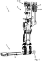
- FIG. 1 shows the figure 1 a perspective view of a manipulator 2 with a crossbar 3 fixed to the manipulator 2, which is also referred to as a crossbar.
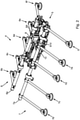
- the figure 2 shows an adapter 4 in a perspective view, which includes a base frame 5 and two toolings 6, 7 connected to the base frame 5 via receptacles.
- the toolings 6, 7 include tooling tubes 6a, 7a and suction grippers 6b to 6f and 7b to 7f connected to the tooling tubes 6a, 7a.
- the base frame 5 is also referred to as a support frame.
- the transfer system 1 includes in the figures 1 and 2 shown components, wherein the adapter 4 is connected in the assembled state to a left arm 3a of the crossbeam 3 and it is provided to connect a further adapter, not shown, to a right arm 3b of the crossbeam 3, which is only partially shown.
- the transfer system 1 includes the manipulator 2 with its crossbar 3, the adapter 4 mounted on the crossbar 3 and a compressed air supply 8.
- the base frame 5 includes a first energy coupling 9 for connecting the first tooling 6 and a second energy coupling 10 for connecting the second tooling 7 (see figure 2 ).
- the transfer system 1 comprises a first supply means 19 connected to the compressed air supply 8 for providing compressed air and vacuum.
- the first supply means 19 is arranged on the base frame 5 or, according to embodiment variants that are not shown, on the crossbeam 3 or on the manipulator 2 .
- the transfer system 1 includes a second supply means 20 connected to the compressed air supply 8 for providing compressed air and vacuum.
- the supply means 20 is arranged on the manipulator 2 (see FIG figure 1 ).
- the transfer system 1 includes a control means 21, which is designed as a switching valve 22 (see figure 1 ).
- first switching position S1 (see figure 5 or 7) of the control means 21, the two tooling tubes 6a, 7a are supplied with compressed air and vacuum via the first supply means 19.
- second switching position S2 (see figure 6 or 8) of the control means 21, the two tooling tubes 6a, 7a are supplied with compressed air and vacuum via the second supply means 20.
- the tooling 6 includes a plug S9, with which it is connected to the first energy coupling 9 of the base frame 5 (see also figure 2 ).
- the tooling 7 also includes a plug S10, with which it is connected to the second energy coupling 10 of the base frame 5 (see also figure 2 ). If operation takes place in the second switching position S2, tooling is installed which includes individual ejectors for vacuum generation, with each suction gripper having a Single ejector is assigned.
- each tooling 6, 7 includes two tabs R6a, R6b or R7a, R7b, which are inserted into associated receptacles A6a, A6b or A7a, A7b of the base frame 5 to connect the tooling 6, 7 to the base frame 5 (cf Figures 3 and 4 ).
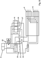
- the first supply means 19 comprises two vacuum generating devices 23, 24.
- the vacuum generating device 23 is connected to the second input 16 of the second energy coupling 10 via a supply line 23a and the vacuum generating device 24 is connected to the first input 11 of the first energy coupling 9 via a supply line 24a.
- compressed air or vacuum is available at the outlets 13 and 18 in each case.
- the vacuum generating devices 23, 24 are designed as pneumatically controlled compact ejectors, which are sold, for example, by J. Schmalz GmbH under the product name SCPi.
- the pneumatic plan also shows that the second supply means 20 includes a first valve 25-1.
- the first valve 25-1 is connected via a supply line 25a to the first input 11 of the first energy clutch 9 and to the first input 15 of the second energy clutch 10 and can make compressed air available via this supply line 25a.
- the second supply means 20 includes a second valve 25-2. This is via a further supply line 25b connected to the second input 12 of the first energy coupling 9 and to the second input 16 of the second energy coupling 10 and can provide compressed air via this supply line 25b.
- the pneumatic plan also shows that switching between the in the figure 5 shown first switching position S1 and in the figure 6 shown second switching position S2 by means of seven check valves 26 to 32 takes place.
- the five check valves 26 to 30 are assigned to the first supply means 19 and the two check valves 31 , 32 are assigned to the second supply means 20 .
- Compressed air is applied to the five shut-off valves 26 to 30 via the changeover valve 22 located in the switching position S1, and they are thereby opened.
- the supply lines 23a and 24a which lead from the first supply means 19 to the energy couplings 9 or 10, are open, so that the energy couplings 9, 10 can be optionally supplied with vacuum or compressed air.
- the check valves 28, 29 are also open, so that the first supply means 19 can be supplied with compressed air from the compressed air supply 8.
- the check valve 30 is also open, so that the first supply means 19 can be supplied with compressed air for control purposes.
- the check valves 31, 32 which are assigned to the second supply means 20, are not acted upon by compressed air in the switching position S1 and are therefore blocked, so that there is no connection between the second supply means 20 and the energy couplings 9, 10.
- the first supply means 19 is arranged on the base frame 5 . According to an embodiment variant that is not shown, provision is also made for arranging this on the crossbeam or on the manipulator.
- the toolings 6, 7 are supplied centrally.
- the exit 14 of Energy coupling 9 and the output 17 of the energy coupling 10 are each closed by a schematically illustrated closure V14 or V17 when the toolings 6, 7 are operated centrally.
- the closures V14, V17 can each be formed by a plug.
- each energy coupling 9, 10 comprises two further inputs to which pre-air and return air are connected. Such an additional supply is optionally provided.
- the in the figures 7 and 8th shown pneumatic diagrams are analogous to those in the figures 5 and 6 shown pneumatic plans executed.
- the first supply means 19 is not equipped with vacuum generating devices, which are designed as pneumatically controlled compact ejectors, but with vacuum generating devices, which are designed as electrically controlled compact ejectors.
- Electrically controlled compact ejectors are sold, for example, by J. Schmalz GmbH under the product name SXMP.
- SXMP product name
- the use of electrically controlled compact ejectors simplifies the pneumatic plan in that only two check valves 26, 27 have to be assigned to the first supply means 19. Accordingly, in switch position S1 (see figure 7 ) the check valves 26, 27 are opened and the check valves 31, 32, which are assigned to the second supply means 20, are closed.
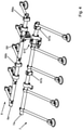
- the transfer system 1 is shown schematically.
- the crossbeam 3 of the manipulator 2 carries the base frame 5 and a further base frame 105.
- the two toolings 6, 7 are arranged on the base frame 5 and two further toolings 106, 107 are arranged on the second base frame 105.
- the transfer device 1 for the toolings 6, 7 comprises the two vacuum generating devices 23, 24 and for the tooling 106, 107 two further vacuum generating devices 123, 124.
Landscapes
- Engineering & Computer Science (AREA)
- Robotics (AREA)
- Mechanical Engineering (AREA)
- Jet Pumps And Other Pumps (AREA)
Claims (10)
- Procédé de fonctionnement d'un système de transfert (1), caractérisé en ce que le système de transfert (1) fonctionne soit dans un premier mode de fonctionnement soit dans un deuxième mode de fonctionnement,- dans le premier mode de fonctionnement, un moyen de commande (21) étant commuté dans une première position de commutation (S1) de sorte qu'un premier moyen d'alimentation (19) soit activé pour alimenter un certain nombre de tubes d'outillage (6a ; 7a) de sorte que de l'air comprimé ou du vide soit fourni par le premier moyen d'alimentation (19) aux tubes d'outillage (6a ; 7a) par le biais d'une conduite d'alimentation (23a ; 24a) au niveau d'un raccord d'énergie respectif (9 ; 10) par tube d'outillage (6a ; 7a),- dans le deuxième mode de fonctionnement, le moyen de commande (21) étant commuté dans une deuxième position de commutation (S2) de sorte qu'un deuxième moyen d'alimentation (20) soit activé pour alimenter ledit nombre de tubes d'outillage (6a, 7a) de sorte que de l'air comprimé destiné au soufflage soit fourni par le deuxième moyen d'alimentation (20) aux tubes d'outillage (6a ; 7a) par le biais d'une première conduite d'alimentation (25b) au niveau du raccord d'énergie respectif (9 ; 10) et que l'air comprimé destiné à la génération de vide soit fourni par le biais d'une deuxième conduite d'alimentation (25a).
- Procédé de fonctionnement d'un système de transfert selon la revendication 1, caractérisé en ce que des vannes d'arrêt (26-30 ; 31, 32), qui sont disposées entre le premier moyen d'alimentation central (19) et le deuxième moyen d'alimentation non-central (20), ferment une alimentation des tubes d'outillage (6a ; 7a) par le deuxième moyen d'alimentation (20) afin que le système de transfert (1) fonctionne dans le premier mode de fonctionnement et une alimentation des tubes d'outillage (6a ; 7a) par le premier moyen d'alimentation (19) afin que le système de transfert (1) fonctionne dans le deuxième mode de fonctionnement.
- Procédé de fonctionnement d'un système de transfert selon la revendication 1 ou 2, caractérisé en ce que, pour que le système de transfert (1) fonctionne dans le premier mode de fonctionnement, pour chaque tube d'outillage (6a ; 7a), une seule sortie (13 ; 18) du raccord d'énergie respectif (9 ; 10) sert à l'alimentation alternative en air comprimé ou en vide et l'autre sortie (14 ; 17) est fermée par une fermeture (V14, V17), en particulier une vanne ou un bouchon, et en ce que, pour que le système de transfert (1) fonctionne dans le deuxième mode de fonctionnement, pour chaque tube d'outillage (6a ; 7a), la première sortie (13 ; 17) du raccord d'énergie respectif (9 ; 10) sert à l'alimentation en air comprimé destiné au soufflage et la deuxième sortie (14 ; 18) du raccord d'énergie respectif (9 ; 10) sert à l'alimentation en air comprimé destiné à la génération de vide.
- Système de transfert (1) destiné à mettre en œuvre un procédé selon l'une des revendications 1 à 3, ledit système comprenant- un manipulateur (2) muni d'une traverse (3),- au moins un adaptateur (4) monté sur la traverse (3),- au moins une alimentation en air comprimé (8),- chaque adaptateur (4) comprenant un cadre de base (5) et au moins un outillage (6 ; 7) pourvu d'un tube d'outillage (6a ; 7a),- chaque cadre de base (5) comprenant au moins un raccord d'énergie (9 ; 10) destiné à l'au moins un tube d'outillage (6a ; 7a),- chaque raccord d'énergie (9 ; 10) destiné à raccorder l'au moins un outillage (6 ; 7) comportant au moins deux sorties (13, 14 ; 17, 18) destinées à l'air comprimé et/ou au vide,- le système de transfert (1) comprenant un premier moyen d'alimentation (19) raccordé à l'alimentation en air comprimé (8) et destiné à fournir de l'air comprimé et du vide, et- le système de transfert (1) comprenant un deuxième moyen d'alimentation (20) raccordé à l'alimentation en air comprimé (8) et destiné à fournir de l'air comprimé,- le système de transfert (1) comprenant un moyen de commande (21),- dans une première position de commutation (S1) du moyen de commande (21), l'au moins un tube d'outillage (6a ; 7a) étant alimenté en air comprimé et en vide par le biais du premier moyen d'alimentation (19) et- dans une deuxième position de commutation (S2) du moyen de commande (21), l'au moins un tube d'outillage (6a ; 7a) étant alimenté en air comprimé par le biais du deuxième moyen d'alimentation (20),caractérisé en ce que- le premier moyen d'alimentation central (19) comprend au moins un dispositif de génération de vide (23, 24) fonctionnant avec de l'air comprimé, et- le deuxième moyen d'alimentation non-central (20) comprend au moins une première vanne (25-1) et une deuxième vanne (25-2),- le premier moyen d'alimentation (19) étant raccordé à une première entrée (11 ; 16) du raccord d'énergie (9 ; 10) du cadre de base (5) et l'alimentant au choix en air comprimé ou en vide et- le deuxième moyen d'alimentation (20) étant raccordé à la première entrée (11 ; 15) et à une deuxième entrée (12 ; 16) du raccord d'énergie (9 ; 10) du cadre de base (5) et alimentant l'une des entrées (11 ; 15) en air comprimé et alimentant également l'autre des entrées (12 ; 16) en air comprimé.
- Système de transfert selon la revendication 4, caractérisé en ce que le moyen de commande (21) et le deuxième moyen d'alimentation non-central (20) sont disposés au niveau du manipulateur (2) ou au niveau de la traverse (3) ou au niveau du cadre de base (5) et en ce que le premier moyen d'alimentation central (19) est disposé au niveau du cadre de base (5) ou de la traverse (3).
- Système de transfert selon la revendication 4 ou 5, caractérisé en ce que le moyen de commande (21) comprend une vanne de commutation (22) et une pluralité de vannes d'arrêt (26-30 ; 31, 32),- les vannes d'arrêt (26-30 ; 31, 32) sont disposés entre le premier moyen d'alimentation (19) et entre le deuxième moyen d'alimentation (20) et l'au moins un raccord d'énergie (9 ; 10) de telle sorte que- dans la première position de commutation (S1) du moyen de commande (21), des lignes d'alimentation (25a ; 25b) entre le deuxième moyen d'alimentation (20) et les entrées (11, 12 ; 15, 16) du raccord d'énergie (9 ; 10) soient bloquées et la ligne d'alimentation ou les lignes d'alimentation (23a ; 24a) entre le premier moyen d'alimentation (19) et l'entrée ou les entrées (11 ; 16) du raccord d'énergie (9 ; 10) soient ouvertes et- dans la deuxième position de commutation (S2) du moyen de commande (21), la ligne d'alimentation ou les lignes d'alimentation (23a ; 24a) entre le premier moyen d'alimentation (19) et l'entrée ou les entrées (11 ; 16) du raccord d'énergie (9 ; 10) soient bloquées et les lignes d'alimentation (25a ; 25b) entre le deuxième moyen d'alimentation (20) et les entrées (11, 12 ; 15, 16) du raccord d'énergie (9 ; 10) soient ouvertes.
- Système de transfert selon l'une des revendications 4 à 6, caractérisé en ce que- l'un des tubes d'outillage (6a ; 7a) est relié à l'un des raccords d'énergie (9 ; 10) de telle sorte que le tube d'outillage (6a ; 7a) et les éléments de préhension par aspiration (6b-6f ; 7b-7f), disposés au niveau de celui-ci, soient reliés dans la première position de commutation (S1) du moyen de commande (21) à l'une des sorties (13 ; 18) du raccord d'énergie (9 ; 10) qui est reliée à l'entrée (11 ; 16) du raccord d'énergie (9 ; 10) qui est raccordée au premier moyen d'alimentation (19), l'autre deuxième sortie respective (14 ; 17) du raccord d'énergie (9 ; 10) étant fermée en particulier par le tube d'outillage (6a ; 7a) ou- l'un des tubes d'outillage (6a ; 7a) est relié à l'un des raccords d'énergie (9 ; 10) de telle sorte que le tube d'outillage (6a ; 7a) et les éléments de préhension par aspiration (6b-6f ; 7b-7f), disposés au niveau de celui-ci, soient reliés dans la deuxième position de commutation (S2) du moyen de commande (21) aux sorties (13, 14 ; 17, 18) du raccord d'énergie (9 ; 10) qui sont reliées aux entrées (11, 12 ; 15, 16) du raccord d'énergie (9 ; 10) qui sont raccordées au deuxième moyen d'alimentation (20).
- Système de transfert selon l'une des revendications 4 à 7, caractérisé en ce que le système de transfert (1) comprend deux cadres de base (5 ; 105) reliés à la traverse (3), chacun avec deux couplages énergétiques (9, 10), et dans lequel le système de transfert (1) comprend quatre tubes d'outillage (6a ; 7a), ceux-ci étant reliés aux quatre couplages énergétiques (9 ; 10) .
- Système de transfert selon la revendication 4, caractérisé en ce que- l'au moins un dispositif de génération de vide (23 ; 24) du premier moyen d'alimentation (19) est conçu comme un dispositif de génération de vide à commande pneumatique pourvu d'un éjecteur compact, ou- l'au moins un dispositif de génération de vide (23 ; 24) du premier moyen d'alimentation (19) est conçu comme un dispositif de génération de vide à commande électrique pourvu d'un éjecteur compact.
- Système de transfert selon l'une au moins des revendications 4 à 9, caractérisé en ce que chaque outillage (6 ; 7), qui fonctionne dans la deuxième position de commutation (S2) du moyen de commande (21), comprend au niveau de chacun de ses éléments de préhension par aspiration (6b-6f ; 7b-7f) un seul éjecteur destiné à la génération de vide.
Applications Claiming Priority (2)
| Application Number | Priority Date | Filing Date | Title |
|---|---|---|---|
| DE102018125276 | 2018-10-12 | ||
| DE102018129041.1A DE102018129041A1 (de) | 2018-10-12 | 2018-11-19 | Verfahren zum Betrieb eines Transfersystems und Transfersystem |
Publications (2)
| Publication Number | Publication Date |
|---|---|
| EP3636397A1 EP3636397A1 (fr) | 2020-04-15 |
| EP3636397B1 true EP3636397B1 (fr) | 2022-03-09 |
Family
ID=67956450
Family Applications (1)
| Application Number | Title | Priority Date | Filing Date |
|---|---|---|---|
| EP19195483.3A Active EP3636397B1 (fr) | 2018-10-12 | 2019-09-05 | Procédé de fonctionnement d'un système de transfert et système de transfert |
Country Status (1)
| Country | Link |
|---|---|
| EP (1) | EP3636397B1 (fr) |
Citations (1)
| Publication number | Priority date | Publication date | Assignee | Title |
|---|---|---|---|---|
| EP3694692A1 (fr) * | 2017-10-11 | 2020-08-19 | Softbox Patents ApS | Base de préhension de robot interchangeable |
Family Cites Families (6)
| Publication number | Priority date | Publication date | Assignee | Title |
|---|---|---|---|---|
| DE102007058114A1 (de) * | 2007-12-04 | 2009-06-10 | Festo Ag & Co. Kg | Vakuumerzeugervorrichtung und Verfahren zu ihrem Betreiben |
| DE102011006826A1 (de) * | 2011-04-06 | 2012-10-11 | J. Schmalz Gmbh | Vorrichtung zum Spannen, Greifen und/oder Manipulieren von Gegenständen mittels Unterdruck |
| ES2845927T3 (es) * | 2014-06-26 | 2021-07-28 | Schmalz J Gmbh | Instalación para la manipulación de piezas de trabajo |
| CA2998128C (fr) * | 2015-09-08 | 2023-11-28 | Berkshire Grey, Inc. | Systemes et procedes pour fournir une acquisition de vide a haut debit dans des systemes automatises |
| DE202016102137U1 (de) | 2016-04-22 | 2016-05-19 | Springer Gmbh | Energiekupplung für eine pneumatische Handhabungsvorrichtung, insbesondere eine pneumatische Greifervorrichtung, und pneumatische Handhabungsvorrichtung, insbesondere pneumatische Greifervorrichtung |
| DE102016011618A1 (de) * | 2016-09-28 | 2018-03-29 | Broetje-Automation Gmbh | Endeffektoranordnung |
-
2019
- 2019-09-05 EP EP19195483.3A patent/EP3636397B1/fr active Active
Patent Citations (1)
| Publication number | Priority date | Publication date | Assignee | Title |
|---|---|---|---|---|
| EP3694692A1 (fr) * | 2017-10-11 | 2020-08-19 | Softbox Patents ApS | Base de préhension de robot interchangeable |
Also Published As
| Publication number | Publication date |
|---|---|
| EP3636397A1 (fr) | 2020-04-15 |
Similar Documents
| Publication | Publication Date | Title |
|---|---|---|
| EP2960024B1 (fr) | Installation de manipulation de pieces a usiner | |
| EP1862237B1 (fr) | Dispositif de saisie d'une pièce à usiner pour changement d'outillage automatique | |
| EP0597418B1 (fr) | Commande électronique pour l'actionnement de la cinématique d'une porte d'avion | |
| CH655034A5 (de) | Einrichtung an einer maschine zur steuerung bzw. ueberwachung. | |
| WO2019072330A1 (fr) | Système d'adaptateurs pour la connexion du dernier maillon d'une chaîne cinématique à un dispositif de manipulation | |
| WO2015074710A1 (fr) | Dispositif et procédé de verrouillage et de déverrouillage d'une plaque de réception | |
| DE102020100567A1 (de) | Handhabungsvorrichtung | |
| WO2015139717A1 (fr) | Dispositif de montage pour le remplacement d'une pointe de préhension appartenant à un doigt de préhension pour un système robotique | |
| DE102007031760A1 (de) | Vakuum-Handhabungsvorrichtung | |
| DE102018129041A1 (de) | Verfahren zum Betrieb eines Transfersystems und Transfersystem | |
| EP3636397B1 (fr) | Procédé de fonctionnement d'un système de transfert et système de transfert | |
| DE102019130054B4 (de) | Unterdruckhandhabungsvorrichtung | |
| DE9211109U1 (de) | Elektro-pneumatische Steuereinrichtung | |
| DE60118296T2 (de) | Gesimsbiegemaschine mit pneumatischem Steuersystem zum Schnellspannen von Gesimsbiegewerkzeugen | |
| DE10338061B4 (de) | Greifervorrichtung | |
| DE102015221259A1 (de) | Ventilmodul und Ventilanordnung | |
| EP2606240A1 (fr) | Dispositif de commande électrofluidique | |
| EP1719720B1 (fr) | Dispositif de contrôle pour une ventouse de préhension | |
| DE3051183C2 (de) | Einrichtung zur Steuerung oder Überwachung von Maschinen | |
| DE102009003516A1 (de) | Automatische Greiferkopplung | |
| DE102005021149B3 (de) | Steuereinrichtung | |
| DE3511965C2 (fr) | ||
| DE3826354C2 (fr) | ||
| DE102021103385A1 (de) | Ventil-Kopplungseinrichtung für fluidführende Leitungen | |
| DE102019006362A1 (de) | Vorrichtung zum Zuführen eines Mediums zu einem Werkzeug einer Bearbeitungsmaschine und Verfahren zum Bereitstellen einer derartigen Vorrichtung |
Legal Events
| Date | Code | Title | Description |
|---|---|---|---|
| PUAI | Public reference made under article 153(3) epc to a published international application that has entered the european phase |
Free format text: ORIGINAL CODE: 0009012 |
|
| STAA | Information on the status of an ep patent application or granted ep patent |
Free format text: STATUS: THE APPLICATION HAS BEEN PUBLISHED |
|
| AK | Designated contracting states |
Kind code of ref document: A1 Designated state(s): AL AT BE BG CH CY CZ DE DK EE ES FI FR GB GR HR HU IE IS IT LI LT LU LV MC MK MT NL NO PL PT RO RS SE SI SK SM TR |
|
| AX | Request for extension of the european patent |
Extension state: BA ME |
|
| STAA | Information on the status of an ep patent application or granted ep patent |
Free format text: STATUS: REQUEST FOR EXAMINATION WAS MADE |
|
| 17P | Request for examination filed |
Effective date: 20200729 |
|
| RBV | Designated contracting states (corrected) |
Designated state(s): AL AT BE BG CH CY CZ DE DK EE ES FI FR GB GR HR HU IE IS IT LI LT LU LV MC MK MT NL NO PL PT RO RS SE SI SK SM TR |
|
| STAA | Information on the status of an ep patent application or granted ep patent |
Free format text: STATUS: EXAMINATION IS IN PROGRESS |
|
| 17Q | First examination report despatched |
Effective date: 20201216 |
|
| GRAP | Despatch of communication of intention to grant a patent |
Free format text: ORIGINAL CODE: EPIDOSNIGR1 |
|
| STAA | Information on the status of an ep patent application or granted ep patent |
Free format text: STATUS: GRANT OF PATENT IS INTENDED |
|
| INTG | Intention to grant announced |
Effective date: 20210927 |
|
| GRAS | Grant fee paid |
Free format text: ORIGINAL CODE: EPIDOSNIGR3 |
|
| GRAA | (expected) grant |
Free format text: ORIGINAL CODE: 0009210 |
|
| STAA | Information on the status of an ep patent application or granted ep patent |
Free format text: STATUS: THE PATENT HAS BEEN GRANTED |
|
| AK | Designated contracting states |
Kind code of ref document: B1 Designated state(s): AL AT BE BG CH CY CZ DE DK EE ES FI FR GB GR HR HU IE IS IT LI LT LU LV MC MK MT NL NO PL PT RO RS SE SI SK SM TR |
|
| REG | Reference to a national code |
Ref country code: CH Ref legal event code: EP Ref country code: AT Ref legal event code: REF Ref document number: 1473729 Country of ref document: AT Kind code of ref document: T Effective date: 20220315 |
|
| REG | Reference to a national code |
Ref country code: DE Ref legal event code: R096 Ref document number: 502019003631 Country of ref document: DE |
|
| REG | Reference to a national code |
Ref country code: IE Ref legal event code: FG4D Free format text: LANGUAGE OF EP DOCUMENT: GERMAN |
|
| REG | Reference to a national code |
Ref country code: LT Ref legal event code: MG9D |
|
| REG | Reference to a national code |
Ref country code: NL Ref legal event code: MP Effective date: 20220309 |
|
| PG25 | Lapsed in a contracting state [announced via postgrant information from national office to epo] |
Ref country code: SE Free format text: LAPSE BECAUSE OF FAILURE TO SUBMIT A TRANSLATION OF THE DESCRIPTION OR TO PAY THE FEE WITHIN THE PRESCRIBED TIME-LIMIT Effective date: 20220309 Ref country code: RS Free format text: LAPSE BECAUSE OF FAILURE TO SUBMIT A TRANSLATION OF THE DESCRIPTION OR TO PAY THE FEE WITHIN THE PRESCRIBED TIME-LIMIT Effective date: 20220309 Ref country code: NO Free format text: LAPSE BECAUSE OF FAILURE TO SUBMIT A TRANSLATION OF THE DESCRIPTION OR TO PAY THE FEE WITHIN THE PRESCRIBED TIME-LIMIT Effective date: 20220609 Ref country code: LT Free format text: LAPSE BECAUSE OF FAILURE TO SUBMIT A TRANSLATION OF THE DESCRIPTION OR TO PAY THE FEE WITHIN THE PRESCRIBED TIME-LIMIT Effective date: 20220309 Ref country code: HR Free format text: LAPSE BECAUSE OF FAILURE TO SUBMIT A TRANSLATION OF THE DESCRIPTION OR TO PAY THE FEE WITHIN THE PRESCRIBED TIME-LIMIT Effective date: 20220309 Ref country code: BG Free format text: LAPSE BECAUSE OF FAILURE TO SUBMIT A TRANSLATION OF THE DESCRIPTION OR TO PAY THE FEE WITHIN THE PRESCRIBED TIME-LIMIT Effective date: 20220609 |
|
| PG25 | Lapsed in a contracting state [announced via postgrant information from national office to epo] |
Ref country code: LV Free format text: LAPSE BECAUSE OF FAILURE TO SUBMIT A TRANSLATION OF THE DESCRIPTION OR TO PAY THE FEE WITHIN THE PRESCRIBED TIME-LIMIT Effective date: 20220309 Ref country code: GR Free format text: LAPSE BECAUSE OF FAILURE TO SUBMIT A TRANSLATION OF THE DESCRIPTION OR TO PAY THE FEE WITHIN THE PRESCRIBED TIME-LIMIT Effective date: 20220610 Ref country code: FI Free format text: LAPSE BECAUSE OF FAILURE TO SUBMIT A TRANSLATION OF THE DESCRIPTION OR TO PAY THE FEE WITHIN THE PRESCRIBED TIME-LIMIT Effective date: 20220309 |
|
| PG25 | Lapsed in a contracting state [announced via postgrant information from national office to epo] |
Ref country code: NL Free format text: LAPSE BECAUSE OF FAILURE TO SUBMIT A TRANSLATION OF THE DESCRIPTION OR TO PAY THE FEE WITHIN THE PRESCRIBED TIME-LIMIT Effective date: 20220309 |
|
| PG25 | Lapsed in a contracting state [announced via postgrant information from national office to epo] |
Ref country code: SM Free format text: LAPSE BECAUSE OF FAILURE TO SUBMIT A TRANSLATION OF THE DESCRIPTION OR TO PAY THE FEE WITHIN THE PRESCRIBED TIME-LIMIT Effective date: 20220309 Ref country code: SK Free format text: LAPSE BECAUSE OF FAILURE TO SUBMIT A TRANSLATION OF THE DESCRIPTION OR TO PAY THE FEE WITHIN THE PRESCRIBED TIME-LIMIT Effective date: 20220309 Ref country code: RO Free format text: LAPSE BECAUSE OF FAILURE TO SUBMIT A TRANSLATION OF THE DESCRIPTION OR TO PAY THE FEE WITHIN THE PRESCRIBED TIME-LIMIT Effective date: 20220309 Ref country code: PT Free format text: LAPSE BECAUSE OF FAILURE TO SUBMIT A TRANSLATION OF THE DESCRIPTION OR TO PAY THE FEE WITHIN THE PRESCRIBED TIME-LIMIT Effective date: 20220711 Ref country code: ES Free format text: LAPSE BECAUSE OF FAILURE TO SUBMIT A TRANSLATION OF THE DESCRIPTION OR TO PAY THE FEE WITHIN THE PRESCRIBED TIME-LIMIT Effective date: 20220309 Ref country code: EE Free format text: LAPSE BECAUSE OF FAILURE TO SUBMIT A TRANSLATION OF THE DESCRIPTION OR TO PAY THE FEE WITHIN THE PRESCRIBED TIME-LIMIT Effective date: 20220309 |
|
| PG25 | Lapsed in a contracting state [announced via postgrant information from national office to epo] |
Ref country code: PL Free format text: LAPSE BECAUSE OF FAILURE TO SUBMIT A TRANSLATION OF THE DESCRIPTION OR TO PAY THE FEE WITHIN THE PRESCRIBED TIME-LIMIT Effective date: 20220309 Ref country code: IS Free format text: LAPSE BECAUSE OF FAILURE TO SUBMIT A TRANSLATION OF THE DESCRIPTION OR TO PAY THE FEE WITHIN THE PRESCRIBED TIME-LIMIT Effective date: 20220709 Ref country code: AL Free format text: LAPSE BECAUSE OF FAILURE TO SUBMIT A TRANSLATION OF THE DESCRIPTION OR TO PAY THE FEE WITHIN THE PRESCRIBED TIME-LIMIT Effective date: 20220309 |
|
| REG | Reference to a national code |
Ref country code: DE Ref legal event code: R097 Ref document number: 502019003631 Country of ref document: DE |
|
| PLBE | No opposition filed within time limit |
Free format text: ORIGINAL CODE: 0009261 |
|
| STAA | Information on the status of an ep patent application or granted ep patent |
Free format text: STATUS: NO OPPOSITION FILED WITHIN TIME LIMIT |
|
| PG25 | Lapsed in a contracting state [announced via postgrant information from national office to epo] |
Ref country code: DK Free format text: LAPSE BECAUSE OF FAILURE TO SUBMIT A TRANSLATION OF THE DESCRIPTION OR TO PAY THE FEE WITHIN THE PRESCRIBED TIME-LIMIT Effective date: 20220309 |
|
| 26N | No opposition filed |
Effective date: 20221212 |
|
| PG25 | Lapsed in a contracting state [announced via postgrant information from national office to epo] |
Ref country code: SI Free format text: LAPSE BECAUSE OF FAILURE TO SUBMIT A TRANSLATION OF THE DESCRIPTION OR TO PAY THE FEE WITHIN THE PRESCRIBED TIME-LIMIT Effective date: 20220309 |
|
| PG25 | Lapsed in a contracting state [announced via postgrant information from national office to epo] |
Ref country code: MC Free format text: LAPSE BECAUSE OF FAILURE TO SUBMIT A TRANSLATION OF THE DESCRIPTION OR TO PAY THE FEE WITHIN THE PRESCRIBED TIME-LIMIT Effective date: 20220309 |
|
| REG | Reference to a national code |
Ref country code: CH Ref legal event code: PL |
|
| REG | Reference to a national code |
Ref country code: BE Ref legal event code: MM Effective date: 20220930 |
|
| PG25 | Lapsed in a contracting state [announced via postgrant information from national office to epo] |
Ref country code: LU Free format text: LAPSE BECAUSE OF NON-PAYMENT OF DUE FEES Effective date: 20220905 |
|
| P01 | Opt-out of the competence of the unified patent court (upc) registered |
Effective date: 20230526 |
|
| PG25 | Lapsed in a contracting state [announced via postgrant information from national office to epo] |
Ref country code: LI Free format text: LAPSE BECAUSE OF NON-PAYMENT OF DUE FEES Effective date: 20220930 Ref country code: IT Free format text: LAPSE BECAUSE OF FAILURE TO SUBMIT A TRANSLATION OF THE DESCRIPTION OR TO PAY THE FEE WITHIN THE PRESCRIBED TIME-LIMIT Effective date: 20220309 Ref country code: IE Free format text: LAPSE BECAUSE OF NON-PAYMENT OF DUE FEES Effective date: 20220905 Ref country code: FR Free format text: LAPSE BECAUSE OF NON-PAYMENT OF DUE FEES Effective date: 20220930 Ref country code: CH Free format text: LAPSE BECAUSE OF NON-PAYMENT OF DUE FEES Effective date: 20220930 |
|
| PG25 | Lapsed in a contracting state [announced via postgrant information from national office to epo] |
Ref country code: BE Free format text: LAPSE BECAUSE OF NON-PAYMENT OF DUE FEES Effective date: 20220930 |
|
| PG25 | Lapsed in a contracting state [announced via postgrant information from national office to epo] |
Ref country code: HU Free format text: LAPSE BECAUSE OF FAILURE TO SUBMIT A TRANSLATION OF THE DESCRIPTION OR TO PAY THE FEE WITHIN THE PRESCRIBED TIME-LIMIT; INVALID AB INITIO Effective date: 20190905 |
|
| PG25 | Lapsed in a contracting state [announced via postgrant information from national office to epo] |
Ref country code: CY Free format text: LAPSE BECAUSE OF FAILURE TO SUBMIT A TRANSLATION OF THE DESCRIPTION OR TO PAY THE FEE WITHIN THE PRESCRIBED TIME-LIMIT Effective date: 20220309 |
|
| PG25 | Lapsed in a contracting state [announced via postgrant information from national office to epo] |
Ref country code: MK Free format text: LAPSE BECAUSE OF FAILURE TO SUBMIT A TRANSLATION OF THE DESCRIPTION OR TO PAY THE FEE WITHIN THE PRESCRIBED TIME-LIMIT Effective date: 20220309 |
|
| PG25 | Lapsed in a contracting state [announced via postgrant information from national office to epo] |
Ref country code: TR Free format text: LAPSE BECAUSE OF FAILURE TO SUBMIT A TRANSLATION OF THE DESCRIPTION OR TO PAY THE FEE WITHIN THE PRESCRIBED TIME-LIMIT Effective date: 20220309 |
|
| PG25 | Lapsed in a contracting state [announced via postgrant information from national office to epo] |
Ref country code: MT Free format text: LAPSE BECAUSE OF FAILURE TO SUBMIT A TRANSLATION OF THE DESCRIPTION OR TO PAY THE FEE WITHIN THE PRESCRIBED TIME-LIMIT Effective date: 20220309 |
|
| REG | Reference to a national code |
Ref country code: DE Ref legal event code: R082 Ref document number: 502019003631 Country of ref document: DE Representative=s name: RAVENSPAT PATENTANWAELTE PARTNERSCHAFT MBB, DE |
|
| PGFP | Annual fee paid to national office [announced via postgrant information from national office to epo] |
Ref country code: DE Payment date: 20250819 Year of fee payment: 7 |
|
| PGFP | Annual fee paid to national office [announced via postgrant information from national office to epo] |
Ref country code: GB Payment date: 20250923 Year of fee payment: 7 |
|
| PGFP | Annual fee paid to national office [announced via postgrant information from national office to epo] |
Ref country code: CZ Payment date: 20250827 Year of fee payment: 7 |
|
| REG | Reference to a national code |
Ref country code: AT Ref legal event code: MM01 Ref document number: 1473729 Country of ref document: AT Kind code of ref document: T Effective date: 20240905 |
|
| PG25 | Lapsed in a contracting state [announced via postgrant information from national office to epo] |
Ref country code: AT Free format text: LAPSE BECAUSE OF NON-PAYMENT OF DUE FEES Effective date: 20240905 |
|
| PGFP | Annual fee paid to national office [announced via postgrant information from national office to epo] |
Ref country code: AT Payment date: 20260410 Year of fee payment: 5 |