EP3636415B1 - Appareil de fabrication additive d'objets tridimensionnels - Google Patents
Appareil de fabrication additive d'objets tridimensionnels Download PDFInfo
- Publication number
- EP3636415B1 EP3636415B1 EP18200248.5A EP18200248A EP3636415B1 EP 3636415 B1 EP3636415 B1 EP 3636415B1 EP 18200248 A EP18200248 A EP 18200248A EP 3636415 B1 EP3636415 B1 EP 3636415B1
- Authority
- EP
- European Patent Office
- Prior art keywords
- optical unit
- radiation
- optical
- condition information
- unit
- Prior art date
- Legal status (The legal status is an assumption and is not a legal conclusion. Google has not performed a legal analysis and makes no representation as to the accuracy of the status listed.)
- Active
Links
Images

Classifications
-
- B—PERFORMING OPERATIONS; TRANSPORTING
- B29—WORKING OF PLASTICS; WORKING OF SUBSTANCES IN A PLASTIC STATE IN GENERAL
- B29C—SHAPING OR JOINING OF PLASTICS; SHAPING OF MATERIAL IN A PLASTIC STATE, NOT OTHERWISE PROVIDED FOR; AFTER-TREATMENT OF THE SHAPED PRODUCTS, e.g. REPAIRING
- B29C64/00—Additive manufacturing, i.e. manufacturing of three-dimensional [3D] objects by additive deposition, additive agglomeration or additive layering, e.g. by 3D printing, stereolithography or selective laser sintering
- B29C64/20—Apparatus for additive manufacturing; Details thereof or accessories therefor
- B29C64/264—Arrangements for irradiation
- B29C64/268—Arrangements for irradiation using laser beams; using electron beams [EB]
-
- B—PERFORMING OPERATIONS; TRANSPORTING
- B29—WORKING OF PLASTICS; WORKING OF SUBSTANCES IN A PLASTIC STATE IN GENERAL
- B29C—SHAPING OR JOINING OF PLASTICS; SHAPING OF MATERIAL IN A PLASTIC STATE, NOT OTHERWISE PROVIDED FOR; AFTER-TREATMENT OF THE SHAPED PRODUCTS, e.g. REPAIRING
- B29C64/00—Additive manufacturing, i.e. manufacturing of three-dimensional [3D] objects by additive deposition, additive agglomeration or additive layering, e.g. by 3D printing, stereolithography or selective laser sintering
- B29C64/10—Processes of additive manufacturing
- B29C64/141—Processes of additive manufacturing using only solid materials
- B29C64/153—Processes of additive manufacturing using only solid materials using layers of powder being selectively joined, e.g. by selective laser sintering or melting
-
- B—PERFORMING OPERATIONS; TRANSPORTING
- B29—WORKING OF PLASTICS; WORKING OF SUBSTANCES IN A PLASTIC STATE IN GENERAL
- B29C—SHAPING OR JOINING OF PLASTICS; SHAPING OF MATERIAL IN A PLASTIC STATE, NOT OTHERWISE PROVIDED FOR; AFTER-TREATMENT OF THE SHAPED PRODUCTS, e.g. REPAIRING
- B29C64/00—Additive manufacturing, i.e. manufacturing of three-dimensional [3D] objects by additive deposition, additive agglomeration or additive layering, e.g. by 3D printing, stereolithography or selective laser sintering
- B29C64/10—Processes of additive manufacturing
-
- B—PERFORMING OPERATIONS; TRANSPORTING
- B29—WORKING OF PLASTICS; WORKING OF SUBSTANCES IN A PLASTIC STATE IN GENERAL
- B29C—SHAPING OR JOINING OF PLASTICS; SHAPING OF MATERIAL IN A PLASTIC STATE, NOT OTHERWISE PROVIDED FOR; AFTER-TREATMENT OF THE SHAPED PRODUCTS, e.g. REPAIRING
- B29C64/00—Additive manufacturing, i.e. manufacturing of three-dimensional [3D] objects by additive deposition, additive agglomeration or additive layering, e.g. by 3D printing, stereolithography or selective laser sintering
- B29C64/20—Apparatus for additive manufacturing; Details thereof or accessories therefor
-
- B—PERFORMING OPERATIONS; TRANSPORTING
- B29—WORKING OF PLASTICS; WORKING OF SUBSTANCES IN A PLASTIC STATE IN GENERAL
- B29C—SHAPING OR JOINING OF PLASTICS; SHAPING OF MATERIAL IN A PLASTIC STATE, NOT OTHERWISE PROVIDED FOR; AFTER-TREATMENT OF THE SHAPED PRODUCTS, e.g. REPAIRING
- B29C64/00—Additive manufacturing, i.e. manufacturing of three-dimensional [3D] objects by additive deposition, additive agglomeration or additive layering, e.g. by 3D printing, stereolithography or selective laser sintering
- B29C64/30—Auxiliary operations or equipment
- B29C64/386—Data acquisition or data processing for additive manufacturing
-
- B—PERFORMING OPERATIONS; TRANSPORTING
- B29—WORKING OF PLASTICS; WORKING OF SUBSTANCES IN A PLASTIC STATE IN GENERAL
- B29C—SHAPING OR JOINING OF PLASTICS; SHAPING OF MATERIAL IN A PLASTIC STATE, NOT OTHERWISE PROVIDED FOR; AFTER-TREATMENT OF THE SHAPED PRODUCTS, e.g. REPAIRING
- B29C64/00—Additive manufacturing, i.e. manufacturing of three-dimensional [3D] objects by additive deposition, additive agglomeration or additive layering, e.g. by 3D printing, stereolithography or selective laser sintering
- B29C64/30—Auxiliary operations or equipment
- B29C64/386—Data acquisition or data processing for additive manufacturing
- B29C64/393—Data acquisition or data processing for additive manufacturing for controlling or regulating additive manufacturing processes
-
- B—PERFORMING OPERATIONS; TRANSPORTING
- B33—ADDITIVE MANUFACTURING TECHNOLOGY
- B33Y—ADDITIVE MANUFACTURING, i.e. MANUFACTURING OF THREE-DIMENSIONAL [3D] OBJECTS BY ADDITIVE DEPOSITION, ADDITIVE AGGLOMERATION OR ADDITIVE LAYERING, e.g. BY 3D PRINTING, STEREOLITHOGRAPHY OR SELECTIVE LASER SINTERING
- B33Y30/00—Apparatus for additive manufacturing; Details thereof or accessories therefor
-
- B—PERFORMING OPERATIONS; TRANSPORTING
- B33—ADDITIVE MANUFACTURING TECHNOLOGY
- B33Y—ADDITIVE MANUFACTURING, i.e. MANUFACTURING OF THREE-DIMENSIONAL [3D] OBJECTS BY ADDITIVE DEPOSITION, ADDITIVE AGGLOMERATION OR ADDITIVE LAYERING, e.g. BY 3D PRINTING, STEREOLITHOGRAPHY OR SELECTIVE LASER SINTERING
- B33Y50/00—Data acquisition or data processing for additive manufacturing
-
- B—PERFORMING OPERATIONS; TRANSPORTING
- B29—WORKING OF PLASTICS; WORKING OF SUBSTANCES IN A PLASTIC STATE IN GENERAL
- B29C—SHAPING OR JOINING OF PLASTICS; SHAPING OF MATERIAL IN A PLASTIC STATE, NOT OTHERWISE PROVIDED FOR; AFTER-TREATMENT OF THE SHAPED PRODUCTS, e.g. REPAIRING
- B29C64/00—Additive manufacturing, i.e. manufacturing of three-dimensional [3D] objects by additive deposition, additive agglomeration or additive layering, e.g. by 3D printing, stereolithography or selective laser sintering
- B29C64/30—Auxiliary operations or equipment
- B29C64/35—Cleaning
-
- B—PERFORMING OPERATIONS; TRANSPORTING
- B29—WORKING OF PLASTICS; WORKING OF SUBSTANCES IN A PLASTIC STATE IN GENERAL
- B29C—SHAPING OR JOINING OF PLASTICS; SHAPING OF MATERIAL IN A PLASTIC STATE, NOT OTHERWISE PROVIDED FOR; AFTER-TREATMENT OF THE SHAPED PRODUCTS, e.g. REPAIRING
- B29C64/00—Additive manufacturing, i.e. manufacturing of three-dimensional [3D] objects by additive deposition, additive agglomeration or additive layering, e.g. by 3D printing, stereolithography or selective laser sintering
- B29C64/30—Auxiliary operations or equipment
- B29C64/364—Conditioning of environment
-
- B—PERFORMING OPERATIONS; TRANSPORTING
- B33—ADDITIVE MANUFACTURING TECHNOLOGY
- B33Y—ADDITIVE MANUFACTURING, i.e. MANUFACTURING OF THREE-DIMENSIONAL [3D] OBJECTS BY ADDITIVE DEPOSITION, ADDITIVE AGGLOMERATION OR ADDITIVE LAYERING, e.g. BY 3D PRINTING, STEREOLITHOGRAPHY OR SELECTIVE LASER SINTERING
- B33Y10/00—Processes of additive manufacturing
-
- B—PERFORMING OPERATIONS; TRANSPORTING
- B33—ADDITIVE MANUFACTURING TECHNOLOGY
- B33Y—ADDITIVE MANUFACTURING, i.e. MANUFACTURING OF THREE-DIMENSIONAL [3D] OBJECTS BY ADDITIVE DEPOSITION, ADDITIVE AGGLOMERATION OR ADDITIVE LAYERING, e.g. BY 3D PRINTING, STEREOLITHOGRAPHY OR SELECTIVE LASER SINTERING
- B33Y50/00—Data acquisition or data processing for additive manufacturing
- B33Y50/02—Data acquisition or data processing for additive manufacturing for controlling or regulating additive manufacturing processes
-
- Y—GENERAL TAGGING OF NEW TECHNOLOGICAL DEVELOPMENTS; GENERAL TAGGING OF CROSS-SECTIONAL TECHNOLOGIES SPANNING OVER SEVERAL SECTIONS OF THE IPC; TECHNICAL SUBJECTS COVERED BY FORMER USPC CROSS-REFERENCE ART COLLECTIONS [XRACs] AND DIGESTS
- Y02—TECHNOLOGIES OR APPLICATIONS FOR MITIGATION OR ADAPTATION AGAINST CLIMATE CHANGE
- Y02P—CLIMATE CHANGE MITIGATION TECHNOLOGIES IN THE PRODUCTION OR PROCESSING OF GOODS
- Y02P10/00—Technologies related to metal processing
- Y02P10/25—Process efficiency
Definitions
- the invention relates to an apparatus for additively manufacturing three-dimensional objects by means of successive layerwise selective consolidation of layers of a build material which can be consolidated by means of an energy source, which apparatus comprises an optical unit with at least one optical surface arranged in a process chamber of the apparatus.
- Apparatuses for additively manufacturing three-dimensional objects comprising optical units with at least one optical surface arranged in a process chamber of the apparatus are generally known from prior art.
- Such apparatuses comprise a process chamber in which additive manufacturing processes are performed, e.g. in which a (powdery) build material is selectively consolidated to successively build the three-dimensional object.
- optical units such as windows of the powder chamber or lenses or the like can be used in the additive manufacturing process.
- Optical surfaces of these optical units e.g. the surfaces of a lens or a window of the process chamber, e.g. a window through which an energy beam can be guided into the process chamber or a window through which an operator or a determination device may monitor the manufacturing process.
- Such optical surfaces are exposed to the environment inside the process chamber, i.e. the optical surface that is arranged in the process chamber, e.g. delimiting the process chamber in case of a window, is in direct contact with the environment in the process chamber.
- residues are generated, such as soot, smoke or smolder or non-consolidated build material particles, which residues may adhere to the optical surface of the at least one optical unit.
- the optical surface is successively contaminated thereby, negatively influencing the transmission behavior of the optical surface.
- an energy beam is at least partially absorbed or scattered/reflected at residues adhered to the optical surface of a window through which the energy beam is coupled/guided into the process chamber.
- the respective optical unit is cleaned or exchanged regularly.
- a cleaning or an exchange of the optical unit is performed in defined time intervals during an additive manufacturing process or between additive manufacturing processes.
- a cleaning or an exchange of the optical unit may become necessary before the defined time interval or before the additive manufacturing process is over, respectively.
- the defined time interval is chosen too short, an exchange or cleaning process is performed too often, wherein the additive manufacturing process is unnecessarily interrupted.
- US 2016/236279 A1 discloses a laser solidification apparatus for building objects by layerwise solidification of powder material.
- KR 100 709 036 B1 discloses a laser annealing apparatus having a detector for detecting contamination of a chamber window.
- the apparatus described herein is an apparatus for additively manufacturing three-dimensional objects, e.g. technical components, by means of successive selective layerwise consolidation of layers of a powdered build material ("build material") which can be consolidated by means of an energy source, e.g. an energy beam, in particular a laser beam.
- a respective build material can be a metal, ceramic or polymer powder.
- a respective energy beam can be a laser beam.
- a respective apparatus can be an apparatus in which an application of build material and a consolidation of build material is performed separately, such as a selective laser sintering apparatus or a selective laser melting apparatus, for instance.
- the successive layerwise selective consolidation of build material may be performed via at least one binding material.
- the binding material may be applied with a corresponding application unit and, for example, irradiated with a suitable energy source, e.g. a UV light source.
- the apparatus may comprise a number of functional units which are used during its operation.
- exemplary functional units are a process chamber, an irradiation device which is adapted to selectively irradiate a build material layer disposed in the process chamber with at least one energy beam, and a stream generating device which is adapted to generate a gaseous fluid stream at least partly streaming through the process chamber with given streaming properties, e.g. a given streaming profile, streaming velocity, etc.
- the gaseous fluid stream is capable of being charged with non-consolidated particulate build material, particularly smoke or smoke residues generated during operation of the apparatus, while streaming through the process chamber.
- the gaseous fluid stream is typically inert, i.e. typically a stream of an inert gas, e.g. argon, nitrogen, carbon dioxide, etc.
- the apparatus comprises at least one determination device with at least one light source and at least one determination unit adapted to determine at least one irradiation parameter of radiation emitted by the light source and reflected at the optical surface of the optical unit, wherein the determination device is adapted to determine at least one condition information of the optical unit based on the determined radiation parameter.
- the determination device can be used to emit radiation via the light source, which is coupled into the optical unit Residues adhered to the optical surface of the optical unit scatter or reflect the radiation, respectively, wherein the determination unit can determine the reflected radiation, in particular at least one radiation parameter of the radiation reflected at the optical surface of the optical unit.
- the determination unit can determine the reflected radiation, in particular at least one radiation parameter of the radiation reflected at the optical surface of the optical unit.
- reflected may refer to any arbitrary way in which a part of the radiation that is generated via the light source is propagating towards the detector.
- radiation is uncoupled from the optical unit due to the residues present on the optical surface.
- radiation may be reflected, scattered or otherwise guided towards /detectable with the determination unit.
- the condition information may preferably relate to a contamination degree of the optical surface of the optical unit, in particular to a contamination with residues, and/or an operational state of the optical unit, in particular an integrity of the optical unit, e.g. indicate whether the optical unit is damaged.
- the term "contamination" may relate to an amount of residues that are adhered to the optical surface of the optical unit. For example, the more residues deposited on the optical surface of the optical unit, the more radiation is guided towards the determination unit. Also, the more residues present on the optical surface, the less radiation, e.g. of an energy beam, can pass the optical unit, as a defined part of the radiation is reflected, scattered or absorbed via the residues. Thus, determining the condition information enables a determination or a decision whether the optical surface of the optical unit needs to be exchanged or cleaned or whether the optical surface is not contaminated with residues.
- the determination unit may be adapted to determine the radiation parameter of radiation emitted from the light source and reflected at at least one particle adhered to the surface of the optical unit.
- optical unit refers to a process window through which the energy beam propagates into the process chamber, e.g. that protects at least one optical component, such as a lens or a lens assembly of an irradiation device, a beam guiding unit, such as a scanner or the like from the conditions inside the process chamber.
- the determination unit may be adapted to determine an intensity of the reflected radiation. Since the intensity of the radiation that is determined via the determination unit directly relates to the intensity of radiation that is reflected at residues adhered to the optical surface of the optical unit, it is possible to use the determined intensity of the reflected radiation for determining the contamination information, preferably relating to a degree of contamination of the optical surface.
- an optical surface of an optical unit that is free of residues does (dependent on how the radiation is incident on / coupled into the optical unit) not reflect any of the radiation emitted from the light source, whereas related with an increasing amount of residues the intensity that is determined via the determination unit increases.
- the light source is adapted to essentially radially couple the emitted radiation into the optical unit with respect to an optical axis of the optical unit. Therefore, The light source is arranged in that the radiation is coupled radially, namely at a rim or an edge, into the optical unit, such as a window or a lens. Thus, the radiation may propagate through the optical unit without any (additional) reflection, if the optical surface of the optical unit is free of residues.
- the term "radially” may therefore, be understood as towards the center or a central plane of the optical unit. Each particle adhered to the optical surface leads to an uncoupling of radiation out of the optical unit (radiation leaving the optical unit) and therefore, radiation being reflected at the optical surface of the optical unit that can be detected via the determination unit.
- the light source may, inter alia, be built as light emitting diode (LED) or the light source may comprise at least one optical fiber via which light can be guided to the optical unit and coupled into the optical unit, as described before.
- the light source may be adapted to emit radiation and couple the radiation into the optical unit.
- the radiation coupled into the optical unit may essentially propagate in parallel to at least one optical surface of the optical unit, wherein the optical unit behaves as a light conductor. In regions in which residues are present on the optical surface, radiation is decoupled from the optical unit and therefore, can be detected via the determination unit. Due to the optical unit conducting the radiation emitted from the light source, a major part of the radiation propagates through the optical unit towards an opposing side of the optical unit with respect to the position of the light source.
- the radiation angle under which the light source emits the radiation is preferably chosen in that the radiation is incident on the optical surface from within the optical unit, but a direct propagation of the radiation from the light source to the determination unit is avoided.
- the determination unit and/or the light source may be arranged in that the radiation emitted from the light source cannot directly propagate to the detector of the determination unit, e.g. can propagate along a direct line from the light source to the detector. Thus, it can be assured that radiation emitted by the light source and detected by the determination unit results from residues present on the optical unit and not from the light source itself.
- a lens hood or a lens shade can be used with the determination unit that limits the angle of acceptance under which radiation emitted from the light source can be received by the determination unit. It is also possible to use a suitable filtering unit, e.g. dampening a certain part of the radiation emitted by the light source.
- the light source may preferably be adapted to emit radiation of a different wavelength than radiation emitted by the energy source, preferably in the visual spectrum, in particular blue light.
- a wavelength of the light source can be chosen.
- the determination device may comprise a filter unit that is adapted to filter radiation deviant from a wavelength of the light source.
- the detector of the determination unit may only be sensitive to the radiation emitted from the light source. For example, radiation emitted from the energy source may be filtered and therefore, it may be avoided that radiation emitted by the energy source is incident on the determination unit. It is also possible that the detector is not sensitive for the radiation emitted from the energy source.
- the light source of the determination device may at least partially be integrated in a frame of the optical unit, preferably in a wall of the process chamber.
- the light source emits radiation radially with respect to the optical axis or a central axis/plane of the optical unit, in particular adapted to radially couple the radiation into the optical unit.
- the light source may further be integrated in a frame of the optical unit, e.g. a frame that at least partially surrounds the optical unit, wherein the light source is protected from the environment inside the process chamber by the integration in the frame of the optical unit.
- the light source may also be integrated into the wall of the process chamber being arranged in that the light source is adapted to radially emit the radiation towards the center of the optical unit.
- the inventive apparatus may further be improved in that the determination device may be adapted to output at least one signal dependent on the determined condition information, in particular with a degree of contamination above a defined threshold value.
- the determination device may continuously or in defined time intervals determine the condition information of the at least one optical unit, e.g. the condition information of a window of the process chamber of the apparatus.
- the defined threshold may be defined in that, for example, the signal can be output above a certain intensity of the radiation that is reflected at the optical surface and determined via the determination unit.
- the determination device may further be adapted to initiate an exchange or a cleaning of the at least one optical surface of the optical unit dependent on the condition information.
- the signal as described before, can be used to initiate an exchange or a cleaning process of the at least one optical surface of the optical unit. Therefore, the cleaning process or the exchange process can be performed based on the need for cleaning or exchanging the optical unit assuring that the optical unit is cleaned or exchanged whenever the amount of residues deposited on the optical surface requires an exchange or a cleaning of the optical surface to prevent negative influences on the additive manufacturing process.
- the determination device or a separate control unit may be adapted to compare a determined condition information before and after a cleaning process and adapted to determine at least one cleaning process parameter, in particular a cleaning efficiency.
- the condition information e.g. the contamination degree of the optical surface is above a defined threshold value
- the determination device continuously determines the condition information, in particular the contamination degree.
- the condition information can be determined before and after a cleaning process has been performed and both values of the determined condition information can be compared.
- the efficiency of the cleaning process e.g. the amount of residues removed via the cleaning process, can be determined.
- the status of the cleaning device e.g. indicating whether the cleaning device itself has to be serviced.
- the at least one condition information may be related via the determination device to at least one process step of an additive manufacturing process performed on the apparatus.
- the condition information for more than one process step of the additive manufacturing apparatus, e.g. for multiple irradiation process steps in which build material is selectively irradiated.
- the condition information e.g. relating to or indicating the degree to which the optical surface is contaminated with residues
- the determination unit may be adapted to locally resolve the condition information, in particular adapted to resolve a condition information for at least two different surfaces of the optical unit.
- the determination unit may be used to locally resolve the condition information, for example different regions of a detector of the determination unit.
- a CCD-chip or a CMOS-sensor may be used to locally resolve the condition information.
- the optical surface may be imaged onto the detector of the determination unit and therefore, the intensity of radiation incident on the individual pixels can be determined.
- a (virtual) map can be generated, preferably a two-dimensional or a three-dimensional map, indicating the locally resolved condition information for manufacturing of at least one layer of the object in the additive manufacturing process.
- the map in particular the two-dimensional map can be used to indicate the condition information of the optical surface two-dimensionally, for example a color-coded information of the contamination degree of the optical surface can be output to an operator of the apparatus.
- the determination device may comprise at least two light sources arranged in a predefined pattern along the at least one edge of the optical unit, preferably equidistantly along the longest edge and/or circumferentially arranged.
- the determination device may comprise more than one light source, for example a plurality of light sources that can be arranged at least partially around the optical unit, in particular in that the light sources can emit radiation that can be coupled into the optical unit, e.g. arranged circumferentially or along the longest edge of the optical unit.
- the optical unit is built as process window in the process chamber of the apparatus, light sources may be arranged in parallel along the longest edge of the rectangular process window.
- the plurality of light sources e.g. at least partially circumferentially around an annular optical unit or the like.
- the plurality of light sources e.g. at least partially circumferentially around an annular optical unit or the like.
- the optical unit is built as or may comprise a window of the process chamber, in particular a window separating an irradiation device from the process chamber.
- the process chamber comprises one or more windows, for example windows that separate an irradiation device from the process chamber.
- the window may be used to protect the irradiation device from the conditions inside the process chamber, in particular heat and residues generated in the additive manufacturing process. As these residues successively contaminate the window by adhering to the window, the intensity of an energy beam that is guided through the window is influenced. In particular, an increasing amount of energy is absorbed by residues adhered to the window.
- the condition information of the window in particular the contamination degree of the window, it is possible to determine when an exchange or a cleaning process of the window is necessary.
- the invention relates a determination device for an apparatus for additively manufacturing three-dimensional objects by means of successive layerwise selective irradiation and consolidation of layers of a build material which can be consolidated by means of an energy source, which apparatus comprises an optical unit with at least one optical surface arranged in a process chamber of the apparatus, wherein the determination device comprises at least one light source and at least one determination unit adapted to determine at least one radiation parameter of radiation emitted from the light source and reflected at the surface of the optical unit, wherein the determination device is adapted to determine at least one condition information of the optical unit based on the determined radiation parameter.
- the invention relates to a method for determining at least one condition information of an optical unit of an apparatus for additively manufacturing three-dimensional objects by means of successive layerwise selective irradiation and consolidation of layers of a build material which can be consolidated by means of an energy source, which apparatus comprises an optical unit with at least one optical surface arranged in a process chamber of the apparatus, wherein at least one radiation parameter of radiation emitted from a light source of a determination device is determined which radiation is reflected from the surface of the optical unit and at least one condition information of the optical unit is determined based on the determined radiation parameter.
- FIG. 1 are schematic diagrams, wherein
- Fig. 1 shows an apparatus 1 for additively manufacturing three-dimensional objects 2 by means of successive layerwise selective consolidation of layers of a build material 3 which can be consolidated by means of an energy source 4, e.g. a laser source adapted to generate an energy beam 5 such as a laser beam.
- the energy beam 5 is guided into a process chamber 6, i.e. a chamber in which the additive manufacturing process for additively manufacturing the three-dimensional object 2 is performed.
- the energy beam 5 is selectively guided across a build plane 7 i.e. the plane in which build material 3 is arranged to be selectively irradiated and consolidated via the energy beam 5.
- residues 8 are generated, such as soot, smoke and smolder or non-consolidated build material particles that are stirred up, for instance.
- the residues 8 can adhere to surfaces inside the process chamber 6, for example an optical surface 9 of an optical unit 10.
- the optical unit 10 is built as window in a wall 11 of the process chamber 6.
- the energy beam 5 passes the optical unit 10 on the beam path along which the energy beam 5 is guided to the build plane 7.
- the apparatus 1 comprises a determination device 12 that comprises a light source 13 and a determination unit 14.
- the light source 13 is adapted to couple radiation 15 into the optical unit 10, in particular couple the radiation 15 radially into the optical unit 10, e.g. towards an optical axis or a central plane of the optical unit 10.
- the optical unit 10 is a rectangular window, wherein the light source 13 is arranged in the wall 11 of the process chamber 6 and adapted to couple the radiation 15 into the optical unit 10 towards a central plane of the optical unit 10.
- the radiation 15 for example a light beam
- the optical unit 10 propagates through the optical unit 10, wherein residues 8 adhered to the optical surface 9 cause radiation 15 or at least a part of the radiation 15 to be decoupled from the optical unit 10 and leave the optical unit 10, e.g. causing a beam reflected towards the determination unit 14. Therefore, a reflected part 16 of the radiation 15 is incident on a detector 17 of the determination unit 14.
- the radiation 15 can be coupled into the optical unit 10 without a reflected part 16 being reflected and decoupled from the optical unit 10 via residues 8.
- the determination unit 14 would not detect radiation and therefore, a "dark field" would be captured via the determination unit 14.
- the condition information that can be generated via the determination device 12 is directly related to the amount of residues 8 deposited on or adhered to the optical surface 9.
- condition information may, inter alia, comprise a contamination degree indicating the degree to which the optical surface 9 is contaminated with residues 8. It is further possible to determine other conditions of the optical surface 9 such as damages, in particular cracks, in the optical surface 9 leading to a decoupling of radiation 15, in particular a reflected part 16 leaving the optical unit 10 towards the determination unit 14.
- the determination unit 14 is adapted to determine an intensity of the reflected part 16 of the radiation 15, wherein dependent on the intensity that has been determined via the determination unit 14, the amount of residues 8 adhered to the optical surface 9 can be determined.
- the determination device 12 is adapted to output at least one signal, in particular a signal can be output to a control unit 18.
- the control unit 18 may therefore, initiate an exchange or a cleaning process of the at least one optical surface 9 of the optical unit 10.
- the condition information that is generated via the determination unit 14, e.g. based on the intensity of the reflected part 16 of the radiation 15 exceeds a defined threshold value, a cleaning process of the optical surface 9 of the optical unit 10 can be deemed necessary and can be initiated.
- condition information is determined continuously or in defined time intervals, wherein it is particularly possible that the condition information can be determined in advance to a cleaning process and after a cleaning process for determining the efficiency of the cleaning process. In other words, it is possible to determine the amount of residues 8 still adhered to the optical surface 9 after a cleaning process has been performed.
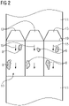
- Fig. 2 shows a top view of the optical unit 10, wherein multiple light sources 13 are provided which are arranged in a defined pattern along a longer edge 19 of the rectangular optical unit 10. Hence, each of the light sources 13 generates radiation 15 coupled into the edge 19 of the optical unit 10.
- the determination unit 14 can determine the intensity of the reflected part 16 of the radiation 15 and therefore, can determine the condition information, in particular the contamination degree. Further, it is possible that the determination unit 14 locally resolves the condition information, e.g. via a detector 17 that is built as a CMOS or CCD-chip, in particular comprising a grid-like shape, for example including a plurality of pixels.
- the condition information can be determined for different positions on the optical unit 10, in particular on the optical surface 9.
- residues 8 adhered to the optical surface 9 are in a critical position through which the energy beam 5 is guided into the process chamber 6, or whether residues 8 are deposited in less important regions of the optical unit 10. Therefore, it is possible to only perform a cleaning process of the optical surface 9, if residues 8 are at least partially adhered to the optical surface 9 in at least one critical position requiring a cleaning of the optical surface 9.
- the map can further be generated as a three-dimensional map, wherein for each layer of the additive manufacturing process, it is possible to locally resolve the condition information.
- the condition information can be stored locally resolved, wherein each process step, such as an irradiation step, can be related to the condition information present during the corresponding irradiation step. Therefore, it is possible to derive whether and to which degree the optical surface 9 was contaminated during the corresponding process step.
- the determination unit 14 may distinguish between the reflected part 16 of radiation 15 reflected from the optical surface 9 that is facing the process chamber 6 and a reflected part 21 of the radiation 15 that is reflected from an optical surface 20 facing the energy source 4, for example facing an irradiation device outside the process chamber 6.
- a contamination of the upper surface of the optical unit 10 for example contaminated via dust or other particles.
- inventive method may be performed on the inventive apparatus 1, preferably using an inventive determination device 12.
Landscapes
- Engineering & Computer Science (AREA)
- Chemical & Material Sciences (AREA)
- Materials Engineering (AREA)
- Manufacturing & Machinery (AREA)
- Physics & Mathematics (AREA)
- Optics & Photonics (AREA)
- Mechanical Engineering (AREA)
- Plasma & Fusion (AREA)
- Health & Medical Sciences (AREA)
- Toxicology (AREA)
- Investigating Materials By The Use Of Optical Means Adapted For Particular Applications (AREA)
Claims (13)
- Appareil (1) de fabrication additive d'objets tridimensionnels (2) au moyen d'une solidification sélective par couches successive de couches d'un matériau de construction (3) qui peut être solidifié au moyen d'une source d'énergie (4), lequel appareil (1) comprend une unité optique (10) construite comme ou comprenant une fenêtre d'une chambre de processus (6) de l'appareil (1), dans lequel l'unité optique (10) comprend au moins une surface optique (9) disposée dans la chambre de processus (6) de l'appareil (1), l'appareil (1) comprenant au moins un dispositif de détermination (12) avec au moins une source de lumière (13) et au moins une unité de détermination (14) adaptée pour déterminer au moins un périmètre de rayonnement du rayonnement (15) émis depuis la source de lumière (13) et réfléchi sur la surface optique (9) de l'unité optique (10), dans lequel le dispositif de détermination (12) est adapté pour déterminer au moins une information de condition de l'unité optique (10) sur la base du paramètre de rayonnement déterminé, dans lequel la source de lumière (13) est adaptée pour injecter sensiblement radialement le rayonnement (15) dans l'unité optique (10) par rapport à un axe optique de l'unité optique (10), dans lequel la source de lumière (13) est disposée de telle manière que le rayonnement est injecté au niveau d'un bord ou d'un rebord dans l'unité optique (10).
- Appareil selon la revendication 1, caractérisé en ce que l'au moins un paramètre de rayonnement du rayonnement (15) est une intensité du rayonnement réfléchi.
- Appareil selon l'une quelconque des revendications précédentes, caractérisé en ce que la source de lumière (13) est adaptée pour émettre un rayonnement (15) d'une longueur d'onde autre que la rayonnement émis par la source d'énergie (4), de préférence dans le spectre visible, en particulier à la lumière bleue.
- Appareil selon l'une quelconque des revendications précédentes, caractérisé en ce que la source de lumière (13) du dispositif de détermination (12) est intégrée au moins en partie dans un châssis de l'unité optique (10), de préférence dans une paroi (11) de la chambre de processus (6).
- Appareil selon l'une quelconque des revendications précédentes, caractérisé en ce que le dispositif de détermination (12) est adapté pour délivrer au moins un signal en fonction de l'information de condition déterminée, en particulier avec un degré de contamination supérieur à un seuil défini.
- Appareil selon l'une quelconque des revendications précédentes, caractérisé en ce que le dispositif de détermination (12) est adapté pour initier un remplacement ou un nettoyage de l'au moins une surface optique (9) de l'unité optique (10) en fonction de l'information de condition.
- Appareil selon l'une quelconque des revendications précédentes, caractérisé en ce que le dispositif de détermination (12) ou une unité de commande séparée (18) est adapté ou adaptée pour comparer une information de condition déterminée avant et après un processus de nettoyage et est adapté ou adaptée pour déterminer au moins un paramètre de processus de nettoyage, en particulier une efficacité de nettoyage.
- Appareil selon l'une quelconque des revendications précédentes, caractérisé en ce que le dispositif de détermination (12) ou une unité de commande séparée (18) est adapté ou adaptée pour rattacher l'au moins une information de condition à au moins une étape de processus d'un processus de fabrication additive réalisé sur l'appareil (1).
- Appareil selon l'une quelconque des revendications précédentes, caractérisé en ce que l'unité de détermination (14) est adaptée pour résoudre localement l'information de condition, en particulier est adaptée pour résoudre une information de condition pour au moins deux surfaces optiques (9, 20) différentes de l'unité optique (10).
- Appareil selon la revendication 9, caractérisé en ce que l'unité de détermination (14) est adaptée pour générer une carte, de préférence une carte bidimensionnelle ou tridimensionnelle, indiquant l'information de condition résolue localement pour la fabrication d'au moins une couche de l'objet (2) dans un processus de fabrication additive.
- Appareil selon l'une quelconque des revendications précédentes, caractérisé en ce que le dispositif de détermination (12) comprend au moins deux sources de lumière (13) disposées selon un modèle prédéfini le long d'au moins un rebord de l'unité optique (10), de préférence à équidistance le long du rebord (19) le plus long et/ou de manière circonférentielle.
- Appareil selon l'une quelconque des revendications précédentes, caractérisé en ce que l'unité optique (10) est fabriquée en tant que ou comprend une fenêtre séparant un dispositif d'irradiation de la chambre de processus (6).
- Procédé permettant de déterminer au moins une information de condition d'une unité optique (10) d'un appareil (1) de fabrication additive d'objets (2) tridimensionnels au moyen d'une solidification sélective par couches successive de couches d'un matériau de construction (3) qui peut être solidifié au moyen d'une source d'énergie (4), lequel appareil (1) comprend une unité optique (10) construite en tant que ou comprenant une fenêtre d'une chambre de processus (6) de l'appareil (1), dans lequel l'unité optique (10) comprend au moins une surface optique (9) disposée dans une chambre de processus (6) de l'appareil (1), le procédé comprenant les étapes : de détermination d'au moins un paramètre de rayonnement du rayonnement (15) émis depuis une source de lumière (13) d'un dispositif de détermination (12), lequel rayonnement est réfléchi depuis la surface optique (9) de l'unité optique (10) et de détermination d'au moins une information de condition de l'unité optique (10) sur la base du paramètre de rayonnement déterminé, dans lequel le rayonnement (15) de la source de lumière (13) est sensiblement injecté radialement dans l'unité optique (10) par rapport à un axe optique de l'unité optique (10), dans lequel la source de lumière (13) est disposée de telle sorte que le rayonnement est injecté au niveau d'un bord ou d'un rebord dans l'unité optique (10).
Priority Applications (2)
| Application Number | Priority Date | Filing Date | Title |
|---|---|---|---|
| EP18200248.5A EP3636415B1 (fr) | 2018-10-12 | 2018-10-12 | Appareil de fabrication additive d'objets tridimensionnels |
| US16/294,063 US11534971B2 (en) | 2018-10-12 | 2019-03-06 | Apparatus for additively manufacturing three-dimensional objects |
Applications Claiming Priority (1)
| Application Number | Priority Date | Filing Date | Title |
|---|---|---|---|
| EP18200248.5A EP3636415B1 (fr) | 2018-10-12 | 2018-10-12 | Appareil de fabrication additive d'objets tridimensionnels |
Publications (2)
| Publication Number | Publication Date |
|---|---|
| EP3636415A1 EP3636415A1 (fr) | 2020-04-15 |
| EP3636415B1 true EP3636415B1 (fr) | 2023-01-04 |
Family
ID=63857724
Family Applications (1)
| Application Number | Title | Priority Date | Filing Date |
|---|---|---|---|
| EP18200248.5A Active EP3636415B1 (fr) | 2018-10-12 | 2018-10-12 | Appareil de fabrication additive d'objets tridimensionnels |
Country Status (2)
| Country | Link |
|---|---|
| US (1) | US11534971B2 (fr) |
| EP (1) | EP3636415B1 (fr) |
Families Citing this family (10)
| Publication number | Priority date | Publication date | Assignee | Title |
|---|---|---|---|---|
| DE102014016679A1 (de) | 2014-11-12 | 2016-05-12 | Cl Schutzrechtsverwaltungs Gmbh | Verfahren und Vorrichtung zur Belichtungssteuerung einer selektiven Lasersinter- oder Laserschmelzvorrichtung |
| JP6907002B2 (ja) * | 2017-04-06 | 2021-07-21 | 株式会社小糸製作所 | 立体面表示装置および車両用表示装置 |
| EP3636415B1 (fr) | 2018-10-12 | 2023-01-04 | Concept Laser GmbH | Appareil de fabrication additive d'objets tridimensionnels |
| FR3111698B1 (fr) * | 2020-06-17 | 2022-12-30 | Safran | Système de détection de défauts dans le chemin optique d’un dispositif de fabrication additive |
| US20220111599A1 (en) * | 2020-10-14 | 2022-04-14 | General Electric Company | Systems and methods for handling optical anomalies on optical elements of an additive manufacturing machine |
| US11752558B2 (en) | 2021-04-16 | 2023-09-12 | General Electric Company | Detecting optical anomalies on optical elements used in an additive manufacturing machine |
| EP4257960A1 (fr) * | 2022-04-06 | 2023-10-11 | TRUMPF Additive Manufacturing Italia S.r.l. | Procédé de surveillance d'au moins une surface d'un élément optique dans un appareil de fabrication additive et appareil de fabrication additive d'un objet |
| GB202207531D0 (en) | 2022-05-23 | 2022-07-06 | Renishaw Plc | Additive manufacturing apparatus and method |
| DE102023112669A1 (de) * | 2023-05-12 | 2024-11-14 | Nikon Slm Solutions Ag | Inspektionsvorrichtung und Inspektionsverfahren zur Erkennung von Anomalien von Optikelementen einer additiven Fertigungseinrichtung |
| DE102023118856A1 (de) * | 2023-07-17 | 2025-01-23 | Dmg Mori Additive Gmbh | Vorrichtung und Verfahren zur Zustandsüberwachung eines Schutzglases einer Fertigungsanlage und Fertigungsanlage für ein additives Fertigungsverfahren |
Family Cites Families (9)
| Publication number | Priority date | Publication date | Assignee | Title |
|---|---|---|---|---|
| US7538310B2 (en) * | 2005-03-31 | 2009-05-26 | Sanyo Electric Co., Ltd. | Laser beam irradiation device with error position detection |
| KR100709036B1 (ko) * | 2005-11-18 | 2007-04-18 | 코닉시스템 주식회사 | 챔버 윈도우 오염 검출장치를 구비하는 레이저 열처리 장치 |
| GB201316815D0 (en) * | 2013-09-23 | 2013-11-06 | Renishaw Plc | Additive manufacturing apparatus and method |
| DE102014209161A1 (de) * | 2014-05-14 | 2015-11-19 | Eos Gmbh Electro Optical Systems | Steuereinheit, Vorrichtung und Verfahren zum Herstellen eines dreidimensionalen Objekts |
| WO2016094827A1 (fr) | 2014-12-12 | 2016-06-16 | Velo3D, Inc. | Systèmes d'asservissement pour l'impression en trois dimensions |
| CN107107482B (zh) * | 2014-12-26 | 2019-11-05 | 松下知识产权经营株式会社 | 三维形状造型物的制造方法 |
| US10611092B2 (en) | 2017-01-05 | 2020-04-07 | Velo3D, Inc. | Optics in three-dimensional printing |
| EP3636415B1 (fr) | 2018-10-12 | 2023-01-04 | Concept Laser GmbH | Appareil de fabrication additive d'objets tridimensionnels |
| US20220111599A1 (en) | 2020-10-14 | 2022-04-14 | General Electric Company | Systems and methods for handling optical anomalies on optical elements of an additive manufacturing machine |
-
2018
- 2018-10-12 EP EP18200248.5A patent/EP3636415B1/fr active Active
-
2019
- 2019-03-06 US US16/294,063 patent/US11534971B2/en active Active
Also Published As
| Publication number | Publication date |
|---|---|
| EP3636415A1 (fr) | 2020-04-15 |
| US20200114580A1 (en) | 2020-04-16 |
| US11534971B2 (en) | 2022-12-27 |
Similar Documents
| Publication | Publication Date | Title |
|---|---|---|
| EP3636415B1 (fr) | Appareil de fabrication additive d'objets tridimensionnels | |
| EP0956498B1 (fr) | Procede et appareil permettant de verifier l'etat d'un verre protecteur lors d'un usinage au laser | |
| CN106733947A (zh) | 一种激光清洗系统及工作方法 | |
| WO2019059250A1 (fr) | Tête de traitement laser et système de traitement laser faisant utilisant celle-ci | |
| US20250085236A1 (en) | Analysis device for condition monitoring of a protective glass of a manufacturing facility and a manufacturing facility for an additive manufacturing process | |
| US20230219165A1 (en) | Device for process monitoring in a deposition welding method | |
| JP6134805B2 (ja) | 光加工ヘッドおよび3次元造形装置 | |
| JP7179278B2 (ja) | 保護ガラスの汚れ検知装置及び保護ガラスの汚れ検知方法 | |
| US11119051B2 (en) | Particle detection for substrate processing | |
| JP6757018B2 (ja) | 保護ガラスの汚れ検出装置とそれを備えるレーザ加工機及び保護ガラスの汚れ検出方法 | |
| JP6982450B2 (ja) | 保護ガラス汚れ検知システム及び方法 | |
| CN111713182B (zh) | 用于保护x射线源的方法以及x射线源 | |
| JP2020179405A (ja) | 保護ガラスのヒューム汚れ検知装置及び検知方法 | |
| CN109421275B (zh) | 用于制造三维物体的设备 | |
| US11034091B2 (en) | Apparatus for additively manufacturing three-dimensional objects | |
| KR102530974B1 (ko) | 분말베드융해 공정 중 발생되는 비정상 흄의 실시간 유동과 농도 측정 장치 및, 이를 이용한 비정상 흄의 실시간 유동과 농도 측정 방법 | |
| CN121100037A (zh) | 用于检测增材制造设备的光学元件的异常的检查装置和检查方法 | |
| CN119654206A (zh) | 用于监测制造系统的保护玻璃的状态的装置和方法以及用于增材制造方法的制造系统 | |
| JP6678907B2 (ja) | 散乱体中における測定対象物の距離計測方法、及びその距離計測装置 | |
| CN118804814A (zh) | 确定透射元件的污垢程度 | |
| EP3560633B1 (fr) | Appareil pour la fabrication additive d'objets tridimensionnels et procédé de détermination au moins un paramètre d'un rayon d'énergie | |
| JPWO2020031406A1 (ja) | レーザ加工装置 | |
| KR102582749B1 (ko) | Mct용 공작물 열처리를 위한 사각빔 형상의 레이저를 조사하는 레이저빔 쉐이핑 장치 | |
| EP4257960A1 (fr) | Procédé de surveillance d'au moins une surface d'un élément optique dans un appareil de fabrication additive et appareil de fabrication additive d'un objet | |
| JP2020157342A (ja) | スパッタ検出装置およびレーザ加工装置 |
Legal Events
| Date | Code | Title | Description |
|---|---|---|---|
| PUAI | Public reference made under article 153(3) epc to a published international application that has entered the european phase |
Free format text: ORIGINAL CODE: 0009012 |
|
| STAA | Information on the status of an ep patent application or granted ep patent |
Free format text: STATUS: THE APPLICATION HAS BEEN PUBLISHED |
|
| AK | Designated contracting states |
Kind code of ref document: A1 Designated state(s): AL AT BE BG CH CY CZ DE DK EE ES FI FR GB GR HR HU IE IS IT LI LT LU LV MC MK MT NL NO PL PT RO RS SE SI SK SM TR |
|
| AX | Request for extension of the european patent |
Extension state: BA ME |
|
| STAA | Information on the status of an ep patent application or granted ep patent |
Free format text: STATUS: REQUEST FOR EXAMINATION WAS MADE |
|
| 17P | Request for examination filed |
Effective date: 20201014 |
|
| RBV | Designated contracting states (corrected) |
Designated state(s): AL AT BE BG CH CY CZ DE DK EE ES FI FR GB GR HR HU IE IS IT LI LT LU LV MC MK MT NL NO PL PT RO RS SE SI SK SM TR |
|
| STAA | Information on the status of an ep patent application or granted ep patent |
Free format text: STATUS: EXAMINATION IS IN PROGRESS |
|
| 17Q | First examination report despatched |
Effective date: 20220201 |
|
| RIC1 | Information provided on ipc code assigned before grant |
Ipc: B29C 64/364 20170101ALN20220715BHEP Ipc: B29C 64/35 20170101ALN20220715BHEP Ipc: B33Y 50/00 20150101ALI20220715BHEP Ipc: B33Y 30/00 20150101ALI20220715BHEP Ipc: B33Y 10/00 20150101ALI20220715BHEP Ipc: B29C 64/153 20170101ALI20220715BHEP Ipc: B29C 64/386 20170101ALI20220715BHEP Ipc: B29C 64/20 20170101AFI20220715BHEP |
|
| REG | Reference to a national code |
Ref country code: DE Ref legal event code: R079 Ref document number: 602018044948 Country of ref document: DE Free format text: PREVIOUS MAIN CLASS: B29C0064153000 Ipc: B29C0064200000 |
|
| GRAP | Despatch of communication of intention to grant a patent |
Free format text: ORIGINAL CODE: EPIDOSNIGR1 |
|
| STAA | Information on the status of an ep patent application or granted ep patent |
Free format text: STATUS: GRANT OF PATENT IS INTENDED |
|
| RIC1 | Information provided on ipc code assigned before grant |
Ipc: B29C 64/364 20170101ALN20220905BHEP Ipc: B29C 64/35 20170101ALN20220905BHEP Ipc: B33Y 50/00 20150101ALI20220905BHEP Ipc: B33Y 30/00 20150101ALI20220905BHEP Ipc: B33Y 10/00 20150101ALI20220905BHEP Ipc: B29C 64/153 20170101ALI20220905BHEP Ipc: B29C 64/386 20170101ALI20220905BHEP Ipc: B29C 64/20 20170101AFI20220905BHEP |
|
| RIC1 | Information provided on ipc code assigned before grant |
Ipc: B29C 64/364 20170101ALN20220909BHEP Ipc: B29C 64/35 20170101ALN20220909BHEP Ipc: B33Y 50/00 20150101ALI20220909BHEP Ipc: B33Y 30/00 20150101ALI20220909BHEP Ipc: B33Y 10/00 20150101ALI20220909BHEP Ipc: B29C 64/153 20170101ALI20220909BHEP Ipc: B29C 64/386 20170101ALI20220909BHEP Ipc: B29C 64/20 20170101AFI20220909BHEP |
|
| INTG | Intention to grant announced |
Effective date: 20220928 |
|
| GRAS | Grant fee paid |
Free format text: ORIGINAL CODE: EPIDOSNIGR3 |
|
| GRAA | (expected) grant |
Free format text: ORIGINAL CODE: 0009210 |
|
| STAA | Information on the status of an ep patent application or granted ep patent |
Free format text: STATUS: THE PATENT HAS BEEN GRANTED |
|
| AK | Designated contracting states |
Kind code of ref document: B1 Designated state(s): AL AT BE BG CH CY CZ DE DK EE ES FI FR GB GR HR HU IE IS IT LI LT LU LV MC MK MT NL NO PL PT RO RS SE SI SK SM TR |
|
| REG | Reference to a national code |
Ref country code: GB Ref legal event code: FG4D |
|
| REG | Reference to a national code |
Ref country code: DE Ref legal event code: R096 Ref document number: 602018044948 Country of ref document: DE |
|
| REG | Reference to a national code |
Ref country code: CH Ref legal event code: EP |
|
| REG | Reference to a national code |
Ref country code: AT Ref legal event code: REF Ref document number: 1541631 Country of ref document: AT Kind code of ref document: T Effective date: 20230115 |
|
| REG | Reference to a national code |
Ref country code: IE Ref legal event code: FG4D |
|
| REG | Reference to a national code |
Ref country code: LT Ref legal event code: MG9D |
|
| REG | Reference to a national code |
Ref country code: NL Ref legal event code: MP Effective date: 20230104 |
|
| REG | Reference to a national code |
Ref country code: AT Ref legal event code: MK05 Ref document number: 1541631 Country of ref document: AT Kind code of ref document: T Effective date: 20230104 |
|
| P01 | Opt-out of the competence of the unified patent court (upc) registered |
Effective date: 20230515 |
|
| PG25 | Lapsed in a contracting state [announced via postgrant information from national office to epo] |
Ref country code: NL Free format text: LAPSE BECAUSE OF FAILURE TO SUBMIT A TRANSLATION OF THE DESCRIPTION OR TO PAY THE FEE WITHIN THE PRESCRIBED TIME-LIMIT Effective date: 20230104 |
|
| PG25 | Lapsed in a contracting state [announced via postgrant information from national office to epo] |
Ref country code: RS Free format text: LAPSE BECAUSE OF FAILURE TO SUBMIT A TRANSLATION OF THE DESCRIPTION OR TO PAY THE FEE WITHIN THE PRESCRIBED TIME-LIMIT Effective date: 20230104 Ref country code: PT Free format text: LAPSE BECAUSE OF FAILURE TO SUBMIT A TRANSLATION OF THE DESCRIPTION OR TO PAY THE FEE WITHIN THE PRESCRIBED TIME-LIMIT Effective date: 20230504 Ref country code: NO Free format text: LAPSE BECAUSE OF FAILURE TO SUBMIT A TRANSLATION OF THE DESCRIPTION OR TO PAY THE FEE WITHIN THE PRESCRIBED TIME-LIMIT Effective date: 20230404 Ref country code: LV Free format text: LAPSE BECAUSE OF FAILURE TO SUBMIT A TRANSLATION OF THE DESCRIPTION OR TO PAY THE FEE WITHIN THE PRESCRIBED TIME-LIMIT Effective date: 20230104 Ref country code: LT Free format text: LAPSE BECAUSE OF FAILURE TO SUBMIT A TRANSLATION OF THE DESCRIPTION OR TO PAY THE FEE WITHIN THE PRESCRIBED TIME-LIMIT Effective date: 20230104 Ref country code: HR Free format text: LAPSE BECAUSE OF FAILURE TO SUBMIT A TRANSLATION OF THE DESCRIPTION OR TO PAY THE FEE WITHIN THE PRESCRIBED TIME-LIMIT Effective date: 20230104 Ref country code: ES Free format text: LAPSE BECAUSE OF FAILURE TO SUBMIT A TRANSLATION OF THE DESCRIPTION OR TO PAY THE FEE WITHIN THE PRESCRIBED TIME-LIMIT Effective date: 20230104 Ref country code: AT Free format text: LAPSE BECAUSE OF FAILURE TO SUBMIT A TRANSLATION OF THE DESCRIPTION OR TO PAY THE FEE WITHIN THE PRESCRIBED TIME-LIMIT Effective date: 20230104 |
|
| PG25 | Lapsed in a contracting state [announced via postgrant information from national office to epo] |
Ref country code: SE Free format text: LAPSE BECAUSE OF FAILURE TO SUBMIT A TRANSLATION OF THE DESCRIPTION OR TO PAY THE FEE WITHIN THE PRESCRIBED TIME-LIMIT Effective date: 20230104 Ref country code: PL Free format text: LAPSE BECAUSE OF FAILURE TO SUBMIT A TRANSLATION OF THE DESCRIPTION OR TO PAY THE FEE WITHIN THE PRESCRIBED TIME-LIMIT Effective date: 20230104 Ref country code: IS Free format text: LAPSE BECAUSE OF FAILURE TO SUBMIT A TRANSLATION OF THE DESCRIPTION OR TO PAY THE FEE WITHIN THE PRESCRIBED TIME-LIMIT Effective date: 20230504 Ref country code: GR Free format text: LAPSE BECAUSE OF FAILURE TO SUBMIT A TRANSLATION OF THE DESCRIPTION OR TO PAY THE FEE WITHIN THE PRESCRIBED TIME-LIMIT Effective date: 20230405 Ref country code: FI Free format text: LAPSE BECAUSE OF FAILURE TO SUBMIT A TRANSLATION OF THE DESCRIPTION OR TO PAY THE FEE WITHIN THE PRESCRIBED TIME-LIMIT Effective date: 20230104 |
|
| REG | Reference to a national code |
Ref country code: DE Ref legal event code: R097 Ref document number: 602018044948 Country of ref document: DE |
|
| PG25 | Lapsed in a contracting state [announced via postgrant information from national office to epo] |
Ref country code: SM Free format text: LAPSE BECAUSE OF FAILURE TO SUBMIT A TRANSLATION OF THE DESCRIPTION OR TO PAY THE FEE WITHIN THE PRESCRIBED TIME-LIMIT Effective date: 20230104 Ref country code: RO Free format text: LAPSE BECAUSE OF FAILURE TO SUBMIT A TRANSLATION OF THE DESCRIPTION OR TO PAY THE FEE WITHIN THE PRESCRIBED TIME-LIMIT Effective date: 20230104 Ref country code: EE Free format text: LAPSE BECAUSE OF FAILURE TO SUBMIT A TRANSLATION OF THE DESCRIPTION OR TO PAY THE FEE WITHIN THE PRESCRIBED TIME-LIMIT Effective date: 20230104 Ref country code: DK Free format text: LAPSE BECAUSE OF FAILURE TO SUBMIT A TRANSLATION OF THE DESCRIPTION OR TO PAY THE FEE WITHIN THE PRESCRIBED TIME-LIMIT Effective date: 20230104 Ref country code: CZ Free format text: LAPSE BECAUSE OF FAILURE TO SUBMIT A TRANSLATION OF THE DESCRIPTION OR TO PAY THE FEE WITHIN THE PRESCRIBED TIME-LIMIT Effective date: 20230104 |
|
| PLBE | No opposition filed within time limit |
Free format text: ORIGINAL CODE: 0009261 |
|
| STAA | Information on the status of an ep patent application or granted ep patent |
Free format text: STATUS: NO OPPOSITION FILED WITHIN TIME LIMIT |
|
| PG25 | Lapsed in a contracting state [announced via postgrant information from national office to epo] |
Ref country code: SK Free format text: LAPSE BECAUSE OF FAILURE TO SUBMIT A TRANSLATION OF THE DESCRIPTION OR TO PAY THE FEE WITHIN THE PRESCRIBED TIME-LIMIT Effective date: 20230104 |
|
| 26N | No opposition filed |
Effective date: 20231005 |
|
| PG25 | Lapsed in a contracting state [announced via postgrant information from national office to epo] |
Ref country code: SI Free format text: LAPSE BECAUSE OF FAILURE TO SUBMIT A TRANSLATION OF THE DESCRIPTION OR TO PAY THE FEE WITHIN THE PRESCRIBED TIME-LIMIT Effective date: 20230104 |
|
| PG25 | Lapsed in a contracting state [announced via postgrant information from national office to epo] |
Ref country code: IT Free format text: LAPSE BECAUSE OF FAILURE TO SUBMIT A TRANSLATION OF THE DESCRIPTION OR TO PAY THE FEE WITHIN THE PRESCRIBED TIME-LIMIT Effective date: 20230104 Ref country code: MC Free format text: LAPSE BECAUSE OF FAILURE TO SUBMIT A TRANSLATION OF THE DESCRIPTION OR TO PAY THE FEE WITHIN THE PRESCRIBED TIME-LIMIT Effective date: 20230104 |
|
| REG | Reference to a national code |
Ref country code: CH Ref legal event code: PL |
|
| REG | Reference to a national code |
Ref country code: BE Ref legal event code: MM Effective date: 20231031 |
|
| PG25 | Lapsed in a contracting state [announced via postgrant information from national office to epo] |
Ref country code: LU Free format text: LAPSE BECAUSE OF NON-PAYMENT OF DUE FEES Effective date: 20231012 |
|
| PG25 | Lapsed in a contracting state [announced via postgrant information from national office to epo] |
Ref country code: LU Free format text: LAPSE BECAUSE OF NON-PAYMENT OF DUE FEES Effective date: 20231012 |
|
| PG25 | Lapsed in a contracting state [announced via postgrant information from national office to epo] |
Ref country code: CH Free format text: LAPSE BECAUSE OF NON-PAYMENT OF DUE FEES Effective date: 20231031 |
|
| PG25 | Lapsed in a contracting state [announced via postgrant information from national office to epo] |
Ref country code: CH Free format text: LAPSE BECAUSE OF NON-PAYMENT OF DUE FEES Effective date: 20231031 |
|
| PG25 | Lapsed in a contracting state [announced via postgrant information from national office to epo] |
Ref country code: BE Free format text: LAPSE BECAUSE OF NON-PAYMENT OF DUE FEES Effective date: 20231031 |
|
| PG25 | Lapsed in a contracting state [announced via postgrant information from national office to epo] |
Ref country code: IE Free format text: LAPSE BECAUSE OF NON-PAYMENT OF DUE FEES Effective date: 20231012 |
|
| PG25 | Lapsed in a contracting state [announced via postgrant information from national office to epo] |
Ref country code: IE Free format text: LAPSE BECAUSE OF NON-PAYMENT OF DUE FEES Effective date: 20231012 |
|
| PG25 | Lapsed in a contracting state [announced via postgrant information from national office to epo] |
Ref country code: BG Free format text: LAPSE BECAUSE OF FAILURE TO SUBMIT A TRANSLATION OF THE DESCRIPTION OR TO PAY THE FEE WITHIN THE PRESCRIBED TIME-LIMIT Effective date: 20230104 |
|
| PG25 | Lapsed in a contracting state [announced via postgrant information from national office to epo] |
Ref country code: BG Free format text: LAPSE BECAUSE OF FAILURE TO SUBMIT A TRANSLATION OF THE DESCRIPTION OR TO PAY THE FEE WITHIN THE PRESCRIBED TIME-LIMIT Effective date: 20230104 |
|
| PG25 | Lapsed in a contracting state [announced via postgrant information from national office to epo] |
Ref country code: CY Free format text: LAPSE BECAUSE OF FAILURE TO SUBMIT A TRANSLATION OF THE DESCRIPTION OR TO PAY THE FEE WITHIN THE PRESCRIBED TIME-LIMIT; INVALID AB INITIO Effective date: 20181012 |
|
| PG25 | Lapsed in a contracting state [announced via postgrant information from national office to epo] |
Ref country code: HU Free format text: LAPSE BECAUSE OF FAILURE TO SUBMIT A TRANSLATION OF THE DESCRIPTION OR TO PAY THE FEE WITHIN THE PRESCRIBED TIME-LIMIT; INVALID AB INITIO Effective date: 20181012 |
|
| PGFP | Annual fee paid to national office [announced via postgrant information from national office to epo] |
Ref country code: GB Payment date: 20250923 Year of fee payment: 8 |
|
| PGFP | Annual fee paid to national office [announced via postgrant information from national office to epo] |
Ref country code: FR Payment date: 20250924 Year of fee payment: 8 |
|
| PG25 | Lapsed in a contracting state [announced via postgrant information from national office to epo] |
Ref country code: TR Free format text: LAPSE BECAUSE OF FAILURE TO SUBMIT A TRANSLATION OF THE DESCRIPTION OR TO PAY THE FEE WITHIN THE PRESCRIBED TIME-LIMIT Effective date: 20230104 |
|
| PGFP | Annual fee paid to national office [announced via postgrant information from national office to epo] |
Ref country code: DE Payment date: 20250923 Year of fee payment: 8 |