EP3636424B1 - Verfahren und vorrichtung zum herstellen von mehrlagigen hülsen für produkte der tabakindustrie - Google Patents
Verfahren und vorrichtung zum herstellen von mehrlagigen hülsen für produkte der tabakindustrie Download PDFInfo
- Publication number
- EP3636424B1 EP3636424B1 EP19201700.2A EP19201700A EP3636424B1 EP 3636424 B1 EP3636424 B1 EP 3636424B1 EP 19201700 A EP19201700 A EP 19201700A EP 3636424 B1 EP3636424 B1 EP 3636424B1
- Authority
- EP
- European Patent Office
- Prior art keywords
- web
- longitudinal strip
- strip
- folding
- deflector
- Prior art date
- Legal status (The legal status is an assumption and is not a legal conclusion. Google has not performed a legal analysis and makes no representation as to the accuracy of the status listed.)
- Active
Links
Images


Classifications
-
- B—PERFORMING OPERATIONS; TRANSPORTING
- B31—MAKING ARTICLES OF PAPER, CARDBOARD OR MATERIAL WORKED IN A MANNER ANALOGOUS TO PAPER; WORKING PAPER, CARDBOARD OR MATERIAL WORKED IN A MANNER ANALOGOUS TO PAPER
- B31C—MAKING WOUND ARTICLES, e.g. WOUND TUBES, OF PAPER, CARDBOARD OR MATERIAL WORKED IN A MANNER ANALOGOUS TO PAPER
- B31C5/00—Making tubes or pipes without using mandrels
-
- A—HUMAN NECESSITIES
- A24—TOBACCO; CIGARS; CIGARETTES; SIMULATED SMOKING DEVICES; SMOKERS' REQUISITES
- A24C—MACHINES FOR MAKING CIGARS OR CIGARETTES
- A24C5/00—Making cigarettes; Making tipping materials for, or attaching filters or mouthpieces to, cigars or cigarettes
- A24C5/46—Making paper tubes for cigarettes
-
- B—PERFORMING OPERATIONS; TRANSPORTING
- B65—CONVEYING; PACKING; STORING; HANDLING THIN OR FILAMENTARY MATERIAL
- B65H—HANDLING THIN OR FILAMENTARY MATERIAL, e.g. SHEETS, WEBS, CABLES
- B65H45/00—Folding thin material
- B65H45/12—Folding articles or webs with application of pressure to define or form crease lines
- B65H45/22—Longitudinal folders, i.e. for folding moving sheet material parallel to the direction of movement
- B65H45/221—Longitudinal folders, i.e. for folding moving sheet material parallel to the direction of movement incorporating folding triangles
Definitions
- This invention relates to a method and a machine for making multilayer tubes of the tobacco industry.
- tube-shaped elements of paper material for example for use as components of traditional cigarettes (to make the filters, for example) or "HNB" (heat-not-burn) cigarettes.
- these tube-shaped elements are made with a multilayer structure.
- these multilayer tube-shaped elements are made by superposing and gluing two paper webs in such a way as to obtain, on one or both of the longitudinal edges, suitable joining zones intended to be spliced to each other to form a tube-like configuration.
- the two webs are offset during superposing and gluing, so that, when the tube is formed, the splices between the corresponding end edges of the two layers are angularly spaced from each other about the axis of the tube itself.
- the basic technical purpose of this invention is to provide a method and a machine for making multilayer tubes of the tobacco industry to overcome the above mentioned disadvantages of the prior art.
- this invention has for an aim to provide a method and a machine for making multilayer tubes of the tobacco industry, capable of guaranteeing a high level of dimensional precision of the end product.
- the machine 1 comprises feed means 2 for feeding a continuous web 100 and configured to feed a continuous web 100 along a feed direction X parallel to the direction of extension of the web 100 and, along the feed path of the web 100, a first folding station 3, followed by another folding station 4.
- Each folding station 3, 4 is configured to fold a respective longitudinal strip of the web 100 onto a second longitudinal strip of the web 100 about a longitudinal fold line which is parallel to the feed direction X so as to obtain a multilayer web having at least two superposed layers.
- a forming station 5 Downstream of the two folding stations 3, 4 there is also a forming station 5 for forming a continuous tube from the multilayer web. More in detail, the forming station 5 is configured for continuously wrapping the multilayer web itself around a longitudinal axis to form a continuous tube with a longitudinal splice.
- an uncoupling and/or tensioning station 6 operating to allow the continuous web 100 to move at different speeds upstream and downstream and/or to tension the web, for example with a "dandy roller" system.
- a cutting station (not illustrated) operating on the continuous tube to make a succession of transverse cuts to obtain a succession of tubes 200 of the tobacco industry.
- tube of the tobacco industry is used to denote a generic tubular element, made, for example, of paper, plastic or metal or combinations thereof, cylindrical in shape, internally hollow and open at both ends.
- the tube may be used directly in the form thus made, in particular internally hollow, to define a segment of a cigarette (traditional, HNB or other type of cigarette) or it may be intended to contain filling material such as tobacco fibre, granules or other material suitable for heat-not-burn (HNB) technology.
- the length of the tube is less than the length of a standard cigarette because the tube is advantageously used to make a cigarette segment.
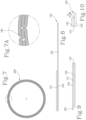
- Figures 7-10 also show a specific embodiment where the longitudinal strips 110, 130 are folded on the same side: that is to say, the second longitudinal strip 130 is folded over onto the first longitudinal strip 110, which had, in its turn, been previously folded over onto the middle longitudinal strip 120 of the web 100.
- the two longitudinal side strips 110, 130 might equally be folded on opposite sides, without departing from the inventive concept.
- Figures 7A and 10 are embodiment details showing the splicing zone where opposite lateral edges of the multilayer web are joined and the related recessed zone 140 ( Figure 10 ) is made to accommodate a protruding splicing edge 160 ( Figure 7A ).
- the recessed zone 140 is obtained by retracting the corresponding edge of the first longitudinal strip 110 in such a way that the folding operations create a longitudinal cavity 150 ( Figure 9 ) that can be compressed to form the recessed zone 140.
- the protruding splicing edge 160 is obtained by suitably adjusting the folding of the third longitudinal strip 130, specifically by laterally offsetting its respective fold line in such a way as to obtain a portion which extends beyond the width of the portion of web 100 that has already been folded ( Figure 9 ).
- both the recessed zone 140 and the protruding splicing edge 160 can be modified as a function of the operating parameters of the folding stations 3, 4, specifically the widths of the longitudinal strips 110, 120, 130 by suitably varying the position of the longitudinal fold lines.
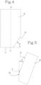
- the first folding station 3 has a first deflector edge 10 disposed and/or configured to deflect the first longitudinal strip 110 of the web 100, and a second deflector edge 11 disposed and/or configured to deflect the second longitudinal strip 120 of the web 100, and, more specifically, the remaining part of the web 100.
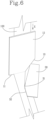
- the deflector edges 10, 11 are shown more clearly in Figures 4-6 .
- the deflector edges 10, 11 are angled to each other.
- the second deflector edge 11 is straight and perpendicular to the feed direction X of the web 100, whilst the first deflector edge 10, which is also straight, is inclined to the second deflector edge 11 at an acute angle ( ⁇ ), preferably included between 40° and 85°, and still more preferably, between 60° and 80°.
- the deflector edges 10, 11 are peripheral edges of the same deflector element 12 which is preferably plate-shaped. More specifically, the deflector element 12 is plate-shaped at least at the parts of it defining the peripheral edges used for folding. This gives the deflector element 12 a flat shape suitable for folding the web.
- the deflector element 12 is associated with a respective gluing device 20 operating on the first strip 110 and/or on the second strip 120 of the web 100 just upstream of folding the first strip 110 and preferably downstream of the second deflector edge 11 to deliver an adhesive substance suitable for holding the first strip 110 on the second strip 120 after folding.
- the web 100 is pre-gummed on specific zones of its surface and the gluing device 20 is replaced by hot-melt or high-pressure adhesive activating means.
- the activating means may be disposed upstream of the folding zone (in the case of hot-melt glue) or downstream of the folding zone (in the case of high-pressure activated glue) to activate the adhesive present in the overlapping zone between the first and the second strip 110, 120 of the web 100.
- the first folding station 3 also comprises an auxiliary guide member 30 located downstream of the first deflector edge 10 to receive and guide the first longitudinal strip 110 of the web 100 as it leaves the first deflector edge 10 and to guide the first strip 110 while it is being folded.
- the auxiliary guide member 30 is configured to slidably receive the first longitudinal strip 110 of the web 100 as it leaves the first deflector edge 10 and to guide the first longitudinal strip 110 while it is being folded completely onto the second longitudinal strip 120.
- the auxiliary guide member 30 is planar and still more preferably, plate-shaped.
- auxiliary guide member 30 and the first deflector edge 10 are disposed in such a way as to come into contact with respective opposite surfaces of the continuous web 100.
- the guide member 30 also has an end edge 32, disposed downstream of the guiding edge 31 and parallel to the feed direction X, at a position such as to substantially coincide with the free longitudinal edge of the first longitudinal strip 110 at the folded position.
- the deflector element 12 defines a positioning plane of the web 100 entering the folding station 3, whilst the auxiliary guide member 30 defines a positioning plane of the continuous web 100 leaving the folding station 3 ( Figures 2 , 3 and 6 ).
- a creasing or scoring station which makes one or more crease lines or lines of weakness intended to coincide with fold lines at a folding station 3, 4.
- the creasing station may comprise, for example, a pair of opposed rollers, at least one of which is provided with a pair of discs or ridges which are axially spaced from each other to make corresponding parallel lines of weakness on the initial web.
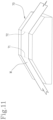
- FIG 11 shows a further component of the machine 1 according to the invention, specifically a stabilizing element 70 configured to stabilize the folds on the multilayer web after all the steps of folding have been carried out.
- the stabilizing element 70 is disposed downstream of the second folding station 4 (or more generally speaking, downstream of the last folding station) and is shaped in such a way as to present one or more deviating edges 71, 72 transverse to the feed direction of the multilayer web.
- the deviating edges 71, 72 have the function of applying a flattening action on the folded edges of the multilayer web (labelled M in Figure 11 ) while the web undergoes a local change in its positioning plane at each deviating edge 71, 72.
- the multilayer web leaving the stabilizing element 70 thus has stable, well-defined folds which have lost any possible curvature that might negatively affect the shape stability of the multilayer web.
- At least one position detector 40 is provided downstream and/or upstream of the folding station 3, 4 to detect a transverse position of the multilayer web 100.
- the machine 1 also comprises a processing unit (not illustrated), connected to the position detector 40 and to the folding station 3, 4, and configured to vary one or more operating parameters of the folding station 3, 4, preferably the width and/or transverse position of the first and/or the third longitudinal strip 110, 130 relative to the second longitudinal strip 120 as a function of the transverse position detected.
- a device (not illustrated) is used to detect at least one diameter value of the continuous tube and/or of at least one tube 200 obtained by cutting the continuous tube.
- the processing unit is also connected to the position detector to vary one or more operating parameters of at least one folding station 3, 4, preferably the width and/or transverse position of the first and/or the third longitudinal strip 110, 130 relative to the second longitudinal strip 120 as a function of the diameter value detected. This allows using feedback to operate on the folding stations 3, 4 to compensate for possible excessive deviations of the real diameter from a reference diameter.
- the machine 1 may further comprise a centring device 50, located preferably upstream of the folding stations 3, 4 for setting a transverse position at least of the continuous web 100 entering the first folding station 3.
- the processing unit is configured to operate also on the centring device 50 to vary, through the centring device 50, the transverse position of the entire continuous web 50 upstream of the folding stations 3, 4 as a function of the transverse position detected by the detecting device 40.
- an adhesive presence and/or properties detector (not illustrated) - for example, a capacitive sensor - for detecting the presence and/or properties of the adhesive substance, interposed between the first and the second longitudinal strip 110, 120 and/or between the second and the third longitudinal strip 120, 130 of the continuous web 100.
- At least one guiding device 60 is preferably provided downstream of each folding station 3, 4 to adjust the transverse position of the web leaving the station 3, 4.
- one or more of the folding stations 3, 4 comprises cooling means to prevent the deflector element 12 and/or the auxiliary guide member 30 from overheating as a result of the web sliding on them.
- the continuous web 100 is fed along the feed direction X, parallel to the direction of extension of the web 100, and then the first longitudinal strip 110 of the web 100 is folded onto the second longitudinal strip 120 about a respective fold line which is parallel to the feed direction X so as to obtain a multilayer web having two superposed layers.
- the third longitudinal strip 130 of the web 100 is then folded onto the second longitudinal strip 120 (onto which the first longitudinal strip 110 had been folded) about a second fold line which is parallel to the feed direction X so as to obtain a multilayer web having three layers.
- the continuous tube is formed by continuously wrapping the multilayer web around a longitudinal axis, in particular by juxtaposing and splicing opposite lateral edges of the multilayer web (for example by joining the recessed portion 140 to the protruding splicing edge 160).
- Each step of folding is accomplished by deflecting the first longitudinal strip 110 of the web 100 around the respective first deflector edge 10 and simultaneously deflecting the second longitudinal strip 120 or, as the case may be, the remaining longitudinal strip, of the web 100 around the second deflector edge 11.
- the deflection of the first longitudinal strip 110 produces a twisting action, or "screwing" motion of its positioning plane such that the first strip 110 is overturned onto the second strip 120
- the deflection of the remaining part or longitudinal strip of the web 100 only changes the inclination of its positioning plane, specifically about an axis (which is substantially defined by the second deflector edge 11) perpendicular to the feed direction X.
- This change in the inclination of the positioning plane defines a "pitching action" at the front of the web, that is to say, a folding action up or down with reference to the feed direction X of the web 100.
- This change in the inclination of the positioning plane, in conjunction with the folding of the first longitudinal strip 110, has the effect of optimizing the superposing geometry of the longitudinal strips, compensating for the greater length of the path that the first longitudinal strip 110 would have to travel in its folding movement if the remaining part of the web 100 were not deflected.
- the invention improves the geometric fit between the layers of the multilayer web, increasing its production precision and regularity.
Landscapes
- Folding Of Thin Sheet-Like Materials, Special Discharging Devices, And Others (AREA)
- Manufacturing Of Cigar And Cigarette Tobacco (AREA)
- Laminated Bodies (AREA)
Claims (26)
- Verfahren zum Herstellen von mehrlagigen Hülsen für die Tabakindustrie, umfassend die folgenden Schritte:- Zuführen einer durchgehenden Bahn (100) entlang einer Zuführungsrichtung (X), die parallel zur Ausdehnungsrichtung der Bahn (100) verläuft;- Falten eines ersten Längsstreifens (110) der Bahn (100) auf einem zweiten Längsstreifen (120) der Bahn (100) um eine Faltlinie, die parallel zur Zuführungsrichtung (X) verläuft, sodass eine mehrlagige Bahn erhalten wird, die mindestens zwei übereinander gelagerte Lagen aufweist;- Formen einer durchgehenden Hülse durch durchgehendes Wickeln der mehrlagigen Bahn rund um eine Längsachse;- Schneiden der durchgehenden Hülse, um eine Abfolge von Hülsen (200) der Tabakindustrie zu erhalten,dadurch gekennzeichnet, dass der Schritt zum Falten durchgeführt wird, indem der erste Längsstreifen (110) der Bahn (100) rund um eine erste Biegekante (10) gebogen wird und indem ein verbleibender Längsstreifen (120, 130) der Bahn (100) rund um eine zweite Biegekante (11) gebogen wird, wobei die erste und die zweite Biegekante (10, 11) zueinander gewinkelt sind, dadurch, dass der Schritt zum Falten auch durch ein Hilfsführungselement (30) durchgeführt wird, das stromabwärts der ersten Biegekante (10) befindlich und ausgelegt ist, um den ersten Längsstreifen (110) der Bahn (100) verschiebbar aufzunehmen, wenn dieser die erste Biegekante (10) verlässt, und um den ersten Längsstreifen (110) progressiv zu führen, während dieser komplett auf dem zweiten Längsstreifen (120) gefaltet wird, und dadurch, dass das Verfahren zudem mindestens einen Schritt zum Auftragen eines Klebstoffs zwischen dem ersten und dem zweiten Längsstreifen (110, 120) umfasst, durchgeführt von einer Verleimungsvorrichtung (20), die mit dem Biegeelement (12) assoziiert ist und auf dem ersten Streifen (110) und/oder dem zweiten Streifen (120) der Bahn (100) genau stromaufwärts des Faltens des ersten Streifens (110) arbeitet, um einen Klebstoff bereitzustellen, der geeignet ist, um den ersten Streifen (110) nach dem Falten auf dem zweiten Streifen (120) zu halten.
- Verfahren nach Anspruch 1, wobei die zweite Biegekante (11) im Wesentlichen gerade und senkrecht zur Zuführungsrichtung (X) angeordnet ist.
- Verfahren nach Anspruch 1 oder 2, wobei die erste Biegekante (10) gerade und zur zweiten Biegekante (11) in einem spitzen Winkel (a) geneigt ist, der vorzugsweise zwischen 40° und 85° und noch besser zwischen 60° und 80° eingeschlossen ist.
- Verfahren nach einem oder mehreren der vorhergehenden Ansprüche, wobei die erste und die zweite Biegekante (10, 11) umfangsseitige und vorzugsweise einfallende Kanten eines einzelnen Biegeelements (12) sind, wobei das Biegeelement (12) vorzugsweise zumindest an den Umfangskanten wie eine Platte ausgeformt ist.
- Verfahren nach Anspruch 4, wobei das Hilfsführungselement (30) ebenflächig ist und vorzugsweise eine plattenähnliche Auslegung aufweist.
- Verfahren nach einem der vorhergehenden Ansprüche, wobei das Hilfsführungselement (30) und die erste Biegekante (10) relativ zur durchgehenden Bahn (100) angeordnet sind, sodass sie mit jeweiligen gegenständigen Oberflächen der durchgehenden Bahn (100) in Kontakt kommen, und wobei das Hilfsführungselement (30) eine Führungskante (31) aufweist, die vorzugsweise gerade und relativ zur Zuführungsrichtung (X) geneigt ist, sodass der erste Längsstreifen (110) progressiv auf dem zweiten Längsstreifen (120) der Bahn (100) gefaltet wird.
- Verfahren nach einem oder mehreren der vorhergehenden Ansprüche, umfassend zwischen dem Schritt zum Falten des ersten Längsstreifens (110) auf dem zweiten Längsstreifen (120) und dem Schritt zum Formen einer durchgehenden Hülse einen weiteren Schritt zum Falten eines dritten Längsstreifens (130) der durchgehenden Bahn (100) auf dem ersten oder zweiten Längsstreifen (110, 120) der durchgehenden Bahn (100), sodass eine dreilagige Bahn geformt wird, wobei der Schritt zum Falten durchgeführt wird, indem der dritte Längsstreifen (130) der durchgehenden Bahn (100) rund um eine jeweilige erste Biegekante (10) gebogen wird und indem ein verbleibender Teil der durchgehenden Bahn (100), insbesondere der vorher überlagerte erste und/oder zweite Längsstreifen (110, 120), rund um eine jeweilige zweite Biegekante (11) gebogen wird, wobei die erste und die zweite Biegekante (10, 11) winkelig zueinander angeordnet sind.
- Verfahren nach Anspruch 7, wobei der erste und/oder der dritte Längsstreifen (110, 130) der durchgehenden Bahn (100) ein Seitenstreifen der durchgehenden Bahn (100) ist bzw. sind, und wobei der zweite Längsstreifen (120) ein mittlerer Streifen der durchgehenden Bahn (100) ist.
- Verfahren nach einem oder mehreren der vorhergehenden Ansprüche, zudem umfassend einen Schritt zum Detektieren einer Querposition der durchgehenden Bahn (100) nach und/oder vor dem Schritt zum Falten mittels mindestens eines Positionsdetektors (40) und einen Schritt zum Variieren von einem oder mehreren Parametern des Schritts zum Falten, vorzugsweise der Breite und/oder der Querposition, des ersten und/oder des dritten Längsstreifens (110, 130) relativ zum zweiten Längsstreifen (120) abhängig von der detektierten Querposition.
- Verfahren nach einem oder mehreren der vorhergehenden Ansprüche, zudem umfassend einen Schritt zum Messen von mindestens einem Durchmesser der durchgehenden Hülse und/oder von mindestens einer Hülse (200) der Tabakindustrie, die durch Schneiden der durchgehenden Hülse gewonnen wurde, und einen Schritt zum Variieren von einem oder mehreren Parametern des Schritts zum Falten, vorzugsweise der Breite und/oder der Querposition, des ersten und/oder dritten Längsstreifens (110, 130) relativ zum zweiten Längsstreifen (120) abhängig von dem mindestens einen gemessenen Durchmesser.
- Verfahren nach einem oder mehreren der vorhergehenden Ansprüche, zudem umfassend mindestens einen Schritt zum Einstellen einer Querposition der durchgehenden Bahn (100) vor dem Schritt zum Falten des ersten Längsstreifens (110) der durchgehenden Bahn (100) mittels einer Zentriervorrichtung (50).
- Verfahren nach Anspruch 4, wobei das Biegeelement (12) eine Positionierungsebene der durchgehenden Bahn (100) vor dem Schritt zum Falten definiert und wobei das Hilfsführungselement (30) eine Positionierungsebene der durchgehenden Bahn (100) nach dem Schritt zum Falten definiert.
- Verfahren nach einem oder mehreren der vorhergehenden Ansprüche, wobei die Verleimungsvorrichtung (20) auf dem ersten Streifen (110) und/oder dem zweiten Streifen (120) der Bahn (100) stromabwärts der ersten Biegekante (11) arbeitet.
- Maschine zum Herstellen von mehrlagigen Hülsen der Tabakindustrie, insbesondere zum Durchführen des Verfahrens nach einem oder mehreren der vorhergehenden Ansprüche, umfassend:- Zuführungsmittel (2) zum Zuführen einer durchgehenden Bahn (100) und ausgelegt, um eine durchgehende Bahn (100) entlang einer Zuführungsrichtung (X) parallel zur Ausdehnungsrichtung der durchgehenden Bahn (100) zuzuführen;- mindestens eine erste Faltstation (3, 4), die ausgelegt ist, um einen ersten Längsstreifen (110) der Bahn (100) auf einem zweiten Längsstreifen (120) der Bahn (100) um eine Faltlinie zu falten, die parallel zur Zuführungsrichtung (X) verläuft, sodass eine mehrlagige Bahn erhalten wird, die mindestens zwei teilweise übereinander gelagerte Lagen aufweist;- eine Formungsstation (5) zum Formen einer durchgehenden Hülse durch durchgehendes Wickeln der mehrlagigen Bahn rund um eine Längsachse;- eine Schneidstation zum Schneiden der durchgehenden Hülse, um eine Abfolge von Hülsen (200) der Tabakindustrie zu erhalten,dadurch gekennzeichnet, dass die mindestens eine Faltstation (3, 4) eine erste Biegekante (10) aufweist, die angeordnet und/oder ausgelegt ist, um den ersten Längsstreifen (110) der durchgehenden Bahn (100) zu biegen, und eine zweite Biegekante (11), die angeordnet und/oder ausgelegt ist, um einen verbleibenden Längsstreifen (120, 130) der Bahn (100) zu biegen, wobei die erste und die zweite Biegekante (10, 11) zueinander gewinkelt sind, dadurch, dass die mindestens eine erste Faltstation (3, 4) auch ein Hilfsführungselement (30) umfasst, das stromabwärts der ersten Biegekante (10) befindlich und ausgelegt ist, um den ersten Längsstreifen (110) der Bahn (100) verschiebbar aufzunehmen, wenn dieser die erste Biegekante (10) verlässt, und um den ersten Längsstreifen (110) progressiv zu führen, während dieser komplett auf dem zweiten Längsstreifen (120) gefaltet wird, und dadurch, dass die Maschine zudem mindestens eine Verleimungsvorrichtung (20) zum Auftragen eines Klebstoffs zwischen dem ersten und dem zweiten Längsstreifen (110, 120) umfasst, und dadurch, dass die Verleimungsvorrichtung (20) mit dem Biegeelement (12) assoziiert ist und auf dem ersten Streifen (110) und/oder dem zweiten Streifen (120) der Bahn (100) genau stromaufwärts des Faltens des ersten Streifens (110) und stromabwärts der zweiten Biegekante (11) arbeitet, um einen Klebstoff bereitzustellen, der geeignet ist, um den ersten Streifen (110) nach dem Falten auf dem zweiten Streifen (120) zu halten.
- Maschine nach Anspruch 14, wobei die zweite Biegekante (11) gerade und senkrecht zur Zuführungsrichtung (X) angeordnet ist.
- Maschine nach Anspruch 14 oder 15, wobei die erste Biegekante (10) gerade und zur zweiten Biegekante (11) in einem spitzen Winkel (a) geneigt ist, der vorzugsweise zwischen 40° und 85° und noch besser zwischen 60° und 80° eingeschlossen ist.
- Maschine nach einem oder mehreren der vorhergehenden Ansprüche 14 bis 16, wobei die erste und die zweite Biegekante (10, 11) umfangsseitige Kanten eines einzelnen Biegeelements (12) sind, wobei das Biegeelement (12) vorzugsweise plattenähnlich ausgeformt ist.
- Maschine nach Anspruch 17, wobei das Hilfsführungselement (30) ebenflächig ist und vorzugsweise eine plattenähnliche Auslegung aufweist.
- Maschine nach einem der vorhergehenden Ansprüche 14 bis 18, wobei das Hilfsführungselement (30) und die erste Biegekante (10) so angeordnet sind, dass sie mit jeweiligen gegenständigen Oberflächen der durchgehenden Bahn (100) in Kontakt kommen, und wobei das Hilfsführungselement (30) eine Führungskante (31) aufweist, die vorzugsweise gerade und relativ zur Zuführungsrichtung (X) geneigt ist, sodass der erste Längsstreifen (110) progressiv auf dem zweiten Längsstreifen (120) der durchgehenden Bahn (100) gefaltet wird.
- Maschine nach einem oder mehreren der vorhergehenden Ansprüche 14 bis 19, zudem umfassend mindestens einen Positionsdetektor (40) stromabwärts und/oder stromaufwärts der mindestens einen ersten Faltstation (30) zum Detektieren einer Querposition der durchgehenden Bahn (100) und eine Verarbeitungseinheit, die mit dem Positionsdetektor (40) und der Faltstation (3, 4) verbunden und ausgelegt ist, um einen oder mehrere Betriebsparameter der Faltstation (3, 4), vorzugsweise die Breite und/oder Querposition, des ersten Längsstreifens (110) relativ zum zweiten Längsstreifen (120) der durchgehenden Bahn (100) abhängig von der detektierten Querposition zu variieren.
- Maschine nach einem oder mehreren der Ansprüche 14 bis 20, zudem umfassend eine zweite Faltstation (4), die stromabwärts der ersten Faltstation (3) befindlich und ausgelegt ist, um einen dritten Längsstreifen (130) der durchgehenden Bahn (100) auf dem zweiten Längsstreifen (120) der durchgehenden Bahn (100) zu falten, sodass eine dreilagige Bahn geformt wird, und wobei die zweite Faltstation (4) eine jeweilige erste Biegekante (10) aufweist, die angeordnet und/oder ausgelegt ist, um den dritten Längsstreifen (130) der durchgehenden Bahn (100) zu biegen, und eine jeweilige zweite Biegekante (11), die angeordnet und/oder ausgelegt ist, um den zweiten Längsstreifen (120) der Bahn zu biegen, wobei die erste und die zweite Biegekante (10, 11) der zweiten Faltstation (4) zueinander gewinkelt sind.
- Maschine nach einem oder mehreren der Ansprüche 14 bis 21, zudem umfassend eine Vorrichtung zum Messen von mindestens einem Durchmesser der durchgehenden Hülse und/oder von mindestens einer Hülse (200) der Tabakindustrie, die durch Schneiden der durchgehenden Hülse gewonnen wurde, und wobei die Maschine (1) zudem eine Verarbeitungseinheit umfasst, die mit der Messvorrichtung und der mindestens einen ersten Faltstation (3, 4) verbunden ist, um einen oder mehrere Betriebsparameter der Faltstation (3, 4), vorzugsweise die Breite und/oder Querposition, des ersten und/oder dritten Längsstreifens (110, 130) relativ zum zweiten Längsstreifen (120) der durchgehenden Bahn abhängig von mindestens einen gemessenen Durchmesser zu variieren.
- Maschine nach einem oder mehreren der Ansprüche 14 bis 22, zudem umfassend eine Zentriervorrichtung (50), die stromaufwärts der mindestens einen ersten Faltstation (3, 4) befindlich ist, um eine Querposition der durchgehenden Bahn (100) einzustellen.
- Maschine nach einem der vorhergehenden Ansprüche 14 bis 23, zudem umfassend einen Detektor, vorzugsweise einen kapazitiven Sensor, der stromabwärts der mindestens einen ersten Faltstation (3, 4) befindlich ist, um die Anwesenheit und/oder Eigenschaften des Klebstoffs zu detektieren, der jeweils zwischen dem ersten und dem zweiten Längsstreifen (110, 120) und/oder zwischen dem zweiten und dem dritten Längsstreifen (120, 130) der durchgehenden Bahn (100) eingefügt ist.
- Maschine nach Anspruch 17, wobei das Biegeelement (12) eine Positionierungsebene der durchgehenden Bahn (100), die in die Faltstation (3, 4) eintritt, definiert, und/oder wobei das Hilfsführungselement (30) eine Positionierungsebene der durchgehenden Bahn (100), die die Faltstation (3, 4) verlässt, definiert.
- Maschine nach einem der vorhergehenden Ansprüche 14 bis 25, wobei die mindestens eine Verleimungsvorrichtung (20) auf dem ersten Streifen (110) und/oder dem zweiten Streifen (120) der Bahn (100) stromabwärts der ersten Biegekante (11) arbeitet.
Applications Claiming Priority (1)
| Application Number | Priority Date | Filing Date | Title |
|---|---|---|---|
| IT102018000009354A IT201800009354A1 (it) | 2018-10-11 | 2018-10-11 | Procedimento e macchina per la realizzazione di tubolari multistrato dell’industria del tabacco |
Publications (3)
| Publication Number | Publication Date |
|---|---|
| EP3636424A2 EP3636424A2 (de) | 2020-04-15 |
| EP3636424A3 EP3636424A3 (de) | 2020-05-27 |
| EP3636424B1 true EP3636424B1 (de) | 2024-12-04 |
Family
ID=64902273
Family Applications (1)
| Application Number | Title | Priority Date | Filing Date |
|---|---|---|---|
| EP19201700.2A Active EP3636424B1 (de) | 2018-10-11 | 2019-10-07 | Verfahren und vorrichtung zum herstellen von mehrlagigen hülsen für produkte der tabakindustrie |
Country Status (3)
| Country | Link |
|---|---|
| EP (1) | EP3636424B1 (de) |
| IT (1) | IT201800009354A1 (de) |
| PL (1) | PL3636424T3 (de) |
Families Citing this family (8)
| Publication number | Priority date | Publication date | Assignee | Title |
|---|---|---|---|---|
| IT202000026353A1 (it) | 2020-11-05 | 2022-05-05 | Gd Spa | Macchina e metodo per la realizzazione di cannucce alimentari |
| IT202000026365A1 (it) | 2020-11-05 | 2022-05-05 | Gd Spa | Macchina e metodo per la realizzazione di cannucce alimentari |
| IT202000026407A1 (it) | 2020-11-05 | 2022-05-05 | Gd Spa | Dispositivo e metodo per la finitura di cannucce alimentari |
| IT202000026377A1 (it) | 2020-11-05 | 2022-05-05 | Gd Spa | Macchina e metodo per la realizzazione di cannucce alimentari |
| IT202100013010A1 (it) | 2021-05-20 | 2022-11-20 | Gd Spa | Macchina e metodo per la realizzazione di spezzoni tubolari, in particolare dell’industria del tabacco o dell’industria delle cannucce |
| IT202100016568A1 (it) | 2021-06-24 | 2022-12-24 | Gd Spa | Macchina e metodo per la realizzazione di tubolari multistrato |
| IT202200019926A1 (it) | 2022-09-28 | 2024-03-28 | Gd Spa | Macchina e procedimento per la formazione di tubolari multistrato |
| IT202300009255A1 (it) | 2023-05-09 | 2024-11-09 | Gd Spa | Metodo e macchina per la formazione di tubolari multistrato |
Citations (1)
| Publication number | Priority date | Publication date | Assignee | Title |
|---|---|---|---|---|
| DE102005046660B4 (de) * | 2005-09-29 | 2016-02-11 | Windmöller & Hölscher Kg | Herstellvorrichtung und -verfahren von Säcken oder Sackhalbzeugen umfassend eine Messung von Leimaufträgen |
Family Cites Families (12)
| Publication number | Priority date | Publication date | Assignee | Title |
|---|---|---|---|---|
| US2956799A (en) * | 1958-04-07 | 1960-10-18 | Harold M Wasson | Tape folder |
| CA848404A (en) * | 1969-06-19 | 1970-08-04 | Rothmans Of Pall Mall Canada Limited | Method and apparatus for making tubes |
| GB1311437A (en) * | 1971-03-10 | 1973-03-28 | British American Tobacco Co | Production of tubes |
| DE2542041A1 (de) * | 1975-09-20 | 1977-03-24 | Hauni Werke Koerber & Co Kg | Verfahren und vorrichtung zum herstellen eines papierrohres fuer rauchartikel-mundstueckhuelsen |
| US4131271A (en) * | 1977-06-13 | 1978-12-26 | Paper Converting Machine Company | Method and apparatus for interfolding |
| US4502675A (en) * | 1983-07-15 | 1985-03-05 | Kimberly-Clark Corporation | Longitudinal folding of webs, folding board system therefor |
| SE503491C2 (sv) * | 1994-10-12 | 1996-06-24 | Tetra Laval Holdings & Finance | Metod och anordning för att styra en tunn materialbana vid formning av materialbanan |
| US7144356B2 (en) * | 2002-05-10 | 2006-12-05 | The Procter & Gamble Company | Adjustable, self-correcting web substrate folding system |
| JP2008265918A (ja) * | 2007-04-18 | 2008-11-06 | Tokyo Kikai Seisakusho Ltd | 輪転機のターンバー装置 |
| RU2712202C2 (ru) * | 2015-08-28 | 2020-01-24 | Филип Моррис Продактс С.А. | Улучшенные трубчатые элементы для курительных изделий |
| ITUB20160048A1 (it) * | 2016-01-26 | 2017-07-26 | Gd Spa | Metodo e macchina per la realizzazione di spezzoni di un baco cilindrico tubolare multistrato adatto alla realizzazione di articoli da fumo sostanzialmente cilindrici e relativi spezzoni. |
| DE102017106992A1 (de) * | 2017-03-31 | 2018-10-04 | Hauni Maschinenbau Gmbh | Verfahren zum Herstellen von wenigstens doppellagigen rohrförmigen Strängen der Tabak verarbeitenden Industrie sowie Vorrichtung zur Herstellung von wenigstens doppellagigen Strängen der Tabak verarbeitenden Industrie |
-
2018
- 2018-10-11 IT IT102018000009354A patent/IT201800009354A1/it unknown
-
2019
- 2019-10-07 EP EP19201700.2A patent/EP3636424B1/de active Active
- 2019-10-07 PL PL19201700.2T patent/PL3636424T3/pl unknown
Patent Citations (1)
| Publication number | Priority date | Publication date | Assignee | Title |
|---|---|---|---|---|
| DE102005046660B4 (de) * | 2005-09-29 | 2016-02-11 | Windmöller & Hölscher Kg | Herstellvorrichtung und -verfahren von Säcken oder Sackhalbzeugen umfassend eine Messung von Leimaufträgen |
Also Published As
| Publication number | Publication date |
|---|---|
| EP3636424A2 (de) | 2020-04-15 |
| EP3636424A3 (de) | 2020-05-27 |
| IT201800009354A1 (it) | 2020-04-11 |
| PL3636424T3 (pl) | 2025-03-31 |
Similar Documents
| Publication | Publication Date | Title |
|---|---|---|
| EP3636424A2 (de) | Verfahren und vorrichtung zum herstellen von mehrlagigen hülsen für produkte der tabakindustrie | |
| JP7115842B2 (ja) | たばこ加工産業の2層状の小管体、並びに、この様式の小管体の製造のための方法 | |
| US8579777B2 (en) | Method and device for producing box of corrugated board sheet | |
| CN108371342B (zh) | 用于制造烟草加工业的条的方法以及条成形装置 | |
| EP3727042B1 (de) | Verfahren und einheit zum crimpen einer materialbahn für die tabakindustrie | |
| TWI487616B (zh) | 容器狀複合物包裝物之製造方法及裝置 | |
| EP2781456B1 (de) | Falzaufbau einer kontinuierlichen Verpackungsfolie, insbesondere Papier, verwendbar in automatischen Verpackungsmaschinen und automatische Verpackungsmaschine mit einem derartigen Falzaufbau | |
| JP7136574B2 (ja) | たばこ加工産業の、少なくとも2層状の管体形状の連続体を製造するための方法、並びに、たばこ加工産業の、少なくとも2層状の管体形状の連続体を製造するための装置 | |
| US12133548B2 (en) | Machine and method for making a continuous tubular element with filling having a spacer and/or filter function | |
| EP0882412A2 (de) | Vorrichtung zum herstellen einer verbundbahn und verfahren | |
| CN115884868B (zh) | 用于制造包括具有间隔和/或过滤功能的填充物的连续管状元件的机器和方法 | |
| US20170190533A1 (en) | Tipping paper feed assenbly for use in smoking article manufacture | |
| EP3784066B1 (de) | Mehrschichtiges rohr der tabakverarbeitenden industrie und verfahren zur herstellung des mehrschichtigen rohres | |
| JP6434961B2 (ja) | 喫煙者商品を生産するための装置 | |
| EP4069591B1 (de) | Vorrichtung zur herstellung von papierverpackungen und verwendungsverfahren | |
| EP3636082B1 (de) | Mehrlagige hülse sowie vorrichtung und verfahren zu deren herstellung | |
| EP2999362B1 (de) | Vorrichtung zur herstellung eines raucherartikels | |
| JP4964228B2 (ja) | 2本の平形チューブ状ウェブの端部を接合する装置および方法 | |
| WO2024256288A2 (de) | Vorrichtung, verfahren und separatorbahn für die energiezellen, insbesondere batteriezellen, produzierende industrie | |
| CN105876849B (zh) | 用于制造烟草加工工业的制品的设备 | |
| EP4340645B1 (de) | Maschine und verfahren zur herstellung von rohrförmigen segmenten, insbesondere der tabakindustrie oder der strohindustrie | |
| JP2018121526A (ja) | 喫煙物品用棒状物品の製造機およびその製造方法 | |
| WO2026062570A1 (en) | A device for processing a web, a semi-finished web, a method for producing a semi-finished web, and a machine for forming at least one rod of the tobacco industry | |
| EP3516969A1 (de) | Maschine und verfahren zur herstellung von filterumhüllungen für die tabakindustrie | |
| NL9300042A (nl) | Inrichting voor het oprollen van een een aantal lagen folie omvattende baan. |
Legal Events
| Date | Code | Title | Description |
|---|---|---|---|
| PUAI | Public reference made under article 153(3) epc to a published international application that has entered the european phase |
Free format text: ORIGINAL CODE: 0009012 |
|
| STAA | Information on the status of an ep patent application or granted ep patent |
Free format text: STATUS: THE APPLICATION HAS BEEN PUBLISHED |
|
| AK | Designated contracting states |
Kind code of ref document: A2 Designated state(s): AL AT BE BG CH CY CZ DE DK EE ES FI FR GB GR HR HU IE IS IT LI LT LU LV MC MK MT NL NO PL PT RO RS SE SI SK SM TR |
|
| AX | Request for extension of the european patent |
Extension state: BA ME |
|
| PUAL | Search report despatched |
Free format text: ORIGINAL CODE: 0009013 |
|
| AK | Designated contracting states |
Kind code of ref document: A3 Designated state(s): AL AT BE BG CH CY CZ DE DK EE ES FI FR GB GR HR HU IE IS IT LI LT LU LV MC MK MT NL NO PL PT RO RS SE SI SK SM TR |
|
| AX | Request for extension of the european patent |
Extension state: BA ME |
|
| RIC1 | Information provided on ipc code assigned before grant |
Ipc: B65H 45/22 20060101ALI20200421BHEP Ipc: B31C 5/00 20060101AFI20200421BHEP Ipc: A24C 5/46 20060101ALI20200421BHEP |
|
| STAA | Information on the status of an ep patent application or granted ep patent |
Free format text: STATUS: REQUEST FOR EXAMINATION WAS MADE |
|
| 17P | Request for examination filed |
Effective date: 20201127 |
|
| RBV | Designated contracting states (corrected) |
Designated state(s): AL AT BE BG CH CY CZ DE DK EE ES FI FR GB GR HR HU IE IS IT LI LT LU LV MC MK MT NL NO PL PT RO RS SE SI SK SM TR |
|
| STAA | Information on the status of an ep patent application or granted ep patent |
Free format text: STATUS: EXAMINATION IS IN PROGRESS |
|
| 17Q | First examination report despatched |
Effective date: 20210528 |
|
| P01 | Opt-out of the competence of the unified patent court (upc) registered |
Effective date: 20230527 |
|
| GRAP | Despatch of communication of intention to grant a patent |
Free format text: ORIGINAL CODE: EPIDOSNIGR1 |
|
| STAA | Information on the status of an ep patent application or granted ep patent |
Free format text: STATUS: GRANT OF PATENT IS INTENDED |
|
| INTG | Intention to grant announced |
Effective date: 20240701 |
|
| GRAS | Grant fee paid |
Free format text: ORIGINAL CODE: EPIDOSNIGR3 |
|
| GRAA | (expected) grant |
Free format text: ORIGINAL CODE: 0009210 |
|
| STAA | Information on the status of an ep patent application or granted ep patent |
Free format text: STATUS: THE PATENT HAS BEEN GRANTED |
|
| AK | Designated contracting states |
Kind code of ref document: B1 Designated state(s): AL AT BE BG CH CY CZ DE DK EE ES FI FR GB GR HR HU IE IS IT LI LT LU LV MC MK MT NL NO PL PT RO RS SE SI SK SM TR |
|
| REG | Reference to a national code |
Ref country code: GB Ref legal event code: FG4D |
|
| REG | Reference to a national code |
Ref country code: CH Ref legal event code: EP |
|
| REG | Reference to a national code |
Ref country code: DE Ref legal event code: R096 Ref document number: 602019062871 Country of ref document: DE |
|
| REG | Reference to a national code |
Ref country code: IE Ref legal event code: FG4D |
|
| REG | Reference to a national code |
Ref country code: NL Ref legal event code: FP |
|
| REG | Reference to a national code |
Ref country code: LT Ref legal event code: MG9D |
|
| PG25 | Lapsed in a contracting state [announced via postgrant information from national office to epo] |
Ref country code: HR Free format text: LAPSE BECAUSE OF FAILURE TO SUBMIT A TRANSLATION OF THE DESCRIPTION OR TO PAY THE FEE WITHIN THE PRESCRIBED TIME-LIMIT Effective date: 20241204 |
|
| PG25 | Lapsed in a contracting state [announced via postgrant information from national office to epo] |
Ref country code: FI Free format text: LAPSE BECAUSE OF FAILURE TO SUBMIT A TRANSLATION OF THE DESCRIPTION OR TO PAY THE FEE WITHIN THE PRESCRIBED TIME-LIMIT Effective date: 20241204 |
|
| PG25 | Lapsed in a contracting state [announced via postgrant information from national office to epo] |
Ref country code: BG Free format text: LAPSE BECAUSE OF FAILURE TO SUBMIT A TRANSLATION OF THE DESCRIPTION OR TO PAY THE FEE WITHIN THE PRESCRIBED TIME-LIMIT Effective date: 20241204 |
|
| PG25 | Lapsed in a contracting state [announced via postgrant information from national office to epo] |
Ref country code: ES Free format text: LAPSE BECAUSE OF FAILURE TO SUBMIT A TRANSLATION OF THE DESCRIPTION OR TO PAY THE FEE WITHIN THE PRESCRIBED TIME-LIMIT Effective date: 20241204 |
|
| PG25 | Lapsed in a contracting state [announced via postgrant information from national office to epo] |
Ref country code: NO Free format text: LAPSE BECAUSE OF FAILURE TO SUBMIT A TRANSLATION OF THE DESCRIPTION OR TO PAY THE FEE WITHIN THE PRESCRIBED TIME-LIMIT Effective date: 20250304 |
|
| PG25 | Lapsed in a contracting state [announced via postgrant information from national office to epo] |
Ref country code: LV Free format text: LAPSE BECAUSE OF FAILURE TO SUBMIT A TRANSLATION OF THE DESCRIPTION OR TO PAY THE FEE WITHIN THE PRESCRIBED TIME-LIMIT Effective date: 20241204 Ref country code: GR Free format text: LAPSE BECAUSE OF FAILURE TO SUBMIT A TRANSLATION OF THE DESCRIPTION OR TO PAY THE FEE WITHIN THE PRESCRIBED TIME-LIMIT Effective date: 20250305 |
|
| PG25 | Lapsed in a contracting state [announced via postgrant information from national office to epo] |
Ref country code: RS Free format text: LAPSE BECAUSE OF FAILURE TO SUBMIT A TRANSLATION OF THE DESCRIPTION OR TO PAY THE FEE WITHIN THE PRESCRIBED TIME-LIMIT Effective date: 20250304 |
|
| REG | Reference to a national code |
Ref country code: AT Ref legal event code: MK05 Ref document number: 1747749 Country of ref document: AT Kind code of ref document: T Effective date: 20241204 |
|
| PG25 | Lapsed in a contracting state [announced via postgrant information from national office to epo] |
Ref country code: SM Free format text: LAPSE BECAUSE OF FAILURE TO SUBMIT A TRANSLATION OF THE DESCRIPTION OR TO PAY THE FEE WITHIN THE PRESCRIBED TIME-LIMIT Effective date: 20241204 |
|
| PG25 | Lapsed in a contracting state [announced via postgrant information from national office to epo] |
Ref country code: IS Free format text: LAPSE BECAUSE OF FAILURE TO SUBMIT A TRANSLATION OF THE DESCRIPTION OR TO PAY THE FEE WITHIN THE PRESCRIBED TIME-LIMIT Effective date: 20250404 |
|
| PG25 | Lapsed in a contracting state [announced via postgrant information from national office to epo] |
Ref country code: PT Free format text: LAPSE BECAUSE OF FAILURE TO SUBMIT A TRANSLATION OF THE DESCRIPTION OR TO PAY THE FEE WITHIN THE PRESCRIBED TIME-LIMIT Effective date: 20250404 |
|
| PG25 | Lapsed in a contracting state [announced via postgrant information from national office to epo] |
Ref country code: EE Free format text: LAPSE BECAUSE OF FAILURE TO SUBMIT A TRANSLATION OF THE DESCRIPTION OR TO PAY THE FEE WITHIN THE PRESCRIBED TIME-LIMIT Effective date: 20241204 |
|
| PG25 | Lapsed in a contracting state [announced via postgrant information from national office to epo] |
Ref country code: AT Free format text: LAPSE BECAUSE OF FAILURE TO SUBMIT A TRANSLATION OF THE DESCRIPTION OR TO PAY THE FEE WITHIN THE PRESCRIBED TIME-LIMIT Effective date: 20241204 Ref country code: RO Free format text: LAPSE BECAUSE OF FAILURE TO SUBMIT A TRANSLATION OF THE DESCRIPTION OR TO PAY THE FEE WITHIN THE PRESCRIBED TIME-LIMIT Effective date: 20241204 |
|
| PG25 | Lapsed in a contracting state [announced via postgrant information from national office to epo] |
Ref country code: SK Free format text: LAPSE BECAUSE OF FAILURE TO SUBMIT A TRANSLATION OF THE DESCRIPTION OR TO PAY THE FEE WITHIN THE PRESCRIBED TIME-LIMIT Effective date: 20241204 |
|
| PG25 | Lapsed in a contracting state [announced via postgrant information from national office to epo] |
Ref country code: CZ Free format text: LAPSE BECAUSE OF FAILURE TO SUBMIT A TRANSLATION OF THE DESCRIPTION OR TO PAY THE FEE WITHIN THE PRESCRIBED TIME-LIMIT Effective date: 20241204 |
|
| PG25 | Lapsed in a contracting state [announced via postgrant information from national office to epo] |
Ref country code: IT Free format text: LAPSE BECAUSE OF FAILURE TO SUBMIT A TRANSLATION OF THE DESCRIPTION OR TO PAY THE FEE WITHIN THE PRESCRIBED TIME-LIMIT Effective date: 20241204 |
|
| REG | Reference to a national code |
Ref country code: DE Ref legal event code: R097 Ref document number: 602019062871 Country of ref document: DE |
|
| PG25 | Lapsed in a contracting state [announced via postgrant information from national office to epo] |
Ref country code: SE Free format text: LAPSE BECAUSE OF FAILURE TO SUBMIT A TRANSLATION OF THE DESCRIPTION OR TO PAY THE FEE WITHIN THE PRESCRIBED TIME-LIMIT Effective date: 20241204 |
|
| PG25 | Lapsed in a contracting state [announced via postgrant information from national office to epo] |
Ref country code: DK Free format text: LAPSE BECAUSE OF FAILURE TO SUBMIT A TRANSLATION OF THE DESCRIPTION OR TO PAY THE FEE WITHIN THE PRESCRIBED TIME-LIMIT Effective date: 20241204 |
|
| PLBE | No opposition filed within time limit |
Free format text: ORIGINAL CODE: 0009261 |
|
| STAA | Information on the status of an ep patent application or granted ep patent |
Free format text: STATUS: NO OPPOSITION FILED WITHIN TIME LIMIT |
|
| PGFP | Annual fee paid to national office [announced via postgrant information from national office to epo] |
Ref country code: PL Payment date: 20250918 Year of fee payment: 7 |
|
| REG | Reference to a national code |
Ref country code: CH Ref legal event code: L10 Free format text: ST27 STATUS EVENT CODE: U-0-0-L10-L00 (AS PROVIDED BY THE NATIONAL OFFICE) Effective date: 20251015 |
|
| 26N | No opposition filed |
Effective date: 20250905 |
|
| PGFP | Annual fee paid to national office [announced via postgrant information from national office to epo] |
Ref country code: NL Payment date: 20251026 Year of fee payment: 7 |
|
| PGFP | Annual fee paid to national office [announced via postgrant information from national office to epo] |
Ref country code: DE Payment date: 20251029 Year of fee payment: 7 |
|
| REG | Reference to a national code |
Ref country code: CH Ref legal event code: H13 Free format text: ST27 STATUS EVENT CODE: U-0-0-H10-H13 (AS PROVIDED BY THE NATIONAL OFFICE) Effective date: 20260527 |
|
| PG25 | Lapsed in a contracting state [announced via postgrant information from national office to epo] |
Ref country code: LU Free format text: LAPSE BECAUSE OF NON-PAYMENT OF DUE FEES Effective date: 20251007 |
|
| REG | Reference to a national code |
Ref country code: BE Ref legal event code: MM Effective date: 20251031 |
|
| GBPC | Gb: european patent ceased through non-payment of renewal fee |
Effective date: 20251007 |
|
| PG25 | Lapsed in a contracting state [announced via postgrant information from national office to epo] |
Ref country code: LT Free format text: LAPSE BECAUSE OF FAILURE TO SUBMIT A TRANSLATION OF THE DESCRIPTION OR TO PAY THE FEE WITHIN THE PRESCRIBED TIME-LIMIT Effective date: 20241204 |
|
| PG25 | Lapsed in a contracting state [announced via postgrant information from national office to epo] |
Ref country code: MC Free format text: LAPSE BECAUSE OF FAILURE TO SUBMIT A TRANSLATION OF THE DESCRIPTION OR TO PAY THE FEE WITHIN THE PRESCRIBED TIME-LIMIT Effective date: 20241204 |
|
| PG25 | Lapsed in a contracting state [announced via postgrant information from national office to epo] |
Ref country code: GB Free format text: LAPSE BECAUSE OF NON-PAYMENT OF DUE FEES Effective date: 20251007 |
|
| PG25 | Lapsed in a contracting state [announced via postgrant information from national office to epo] |
Ref country code: BE Free format text: LAPSE BECAUSE OF NON-PAYMENT OF DUE FEES Effective date: 20251031 Ref country code: CH Free format text: LAPSE BECAUSE OF NON-PAYMENT OF DUE FEES Effective date: 20251031 |
|
| PG25 | Lapsed in a contracting state [announced via postgrant information from national office to epo] |
Ref country code: FR Free format text: LAPSE BECAUSE OF NON-PAYMENT OF DUE FEES Effective date: 20251031 |