EP3636452A1 - Pneu - Google Patents
Pneu Download PDFInfo
- Publication number
- EP3636452A1 EP3636452A1 EP18812916.7A EP18812916A EP3636452A1 EP 3636452 A1 EP3636452 A1 EP 3636452A1 EP 18812916 A EP18812916 A EP 18812916A EP 3636452 A1 EP3636452 A1 EP 3636452A1
- Authority
- EP
- European Patent Office
- Prior art keywords
- tire
- belt
- resin
- cord
- tread
- Prior art date
- Legal status (The legal status is an assumption and is not a legal conclusion. Google has not performed a legal analysis and makes no representation as to the accuracy of the status listed.)
- Withdrawn
Links
- 230000003014 reinforcing effect Effects 0.000 claims abstract description 76
- 229920005989 resin Polymers 0.000 claims abstract description 73
- 239000011347 resin Substances 0.000 claims abstract description 73
- 239000000463 material Substances 0.000 claims abstract description 41
- 229920001971 elastomer Polymers 0.000 claims abstract description 35
- 239000005060 rubber Substances 0.000 claims abstract description 29
- 229910000831 Steel Inorganic materials 0.000 claims description 7
- 239000010959 steel Substances 0.000 claims description 7
- 230000002787 reinforcement Effects 0.000 claims description 2
- 239000011324 bead Substances 0.000 description 19
- 238000001816 cooling Methods 0.000 description 12
- 229920005992 thermoplastic resin Polymers 0.000 description 9
- 239000000835 fiber Substances 0.000 description 8
- 229920001225 polyester resin Polymers 0.000 description 8
- 229920002725 thermoplastic elastomer Polymers 0.000 description 8
- 239000000806 elastomer Substances 0.000 description 6
- 238000003466 welding Methods 0.000 description 6
- -1 cord Substances 0.000 description 5
- 239000002184 metal Substances 0.000 description 5
- 229910052751 metal Inorganic materials 0.000 description 5
- 239000012466 permeate Substances 0.000 description 5
- 238000003825 pressing Methods 0.000 description 5
- 229920001169 thermoplastic Polymers 0.000 description 5
- 239000004831 Hot glue Substances 0.000 description 4
- 150000001336 alkenes Chemical class 0.000 description 4
- 150000001875 compounds Chemical class 0.000 description 4
- 238000000034 method Methods 0.000 description 4
- JRZJOMJEPLMPRA-UHFFFAOYSA-N olefin Natural products CCCCCCCC=C JRZJOMJEPLMPRA-UHFFFAOYSA-N 0.000 description 4
- 229920000642 polymer Polymers 0.000 description 4
- 229920001187 thermosetting polymer Polymers 0.000 description 4
- 239000004416 thermosoftening plastic Substances 0.000 description 4
- 238000004073 vulcanization Methods 0.000 description 4
- ZMANZCXQSJIPKH-UHFFFAOYSA-N Triethylamine Chemical compound CCN(CC)CC ZMANZCXQSJIPKH-UHFFFAOYSA-N 0.000 description 3
- 239000000853 adhesive Substances 0.000 description 3
- 230000001070 adhesive effect Effects 0.000 description 3
- 239000005038 ethylene vinyl acetate Substances 0.000 description 3
- 238000004519 manufacturing process Methods 0.000 description 3
- 229920001200 poly(ethylene-vinyl acetate) Polymers 0.000 description 3
- 229920002397 thermoplastic olefin Polymers 0.000 description 3
- 229920006345 thermoplastic polyamide Polymers 0.000 description 3
- XLYOFNOQVPJJNP-UHFFFAOYSA-N water Substances O XLYOFNOQVPJJNP-UHFFFAOYSA-N 0.000 description 3
- 238000004804 winding Methods 0.000 description 3
- QGZKDVFQNNGYKY-UHFFFAOYSA-N Ammonia Chemical compound N QGZKDVFQNNGYKY-UHFFFAOYSA-N 0.000 description 2
- PAYRUJLWNCNPSJ-UHFFFAOYSA-N Aniline Chemical compound NC1=CC=CC=C1 PAYRUJLWNCNPSJ-UHFFFAOYSA-N 0.000 description 2
- OKTJSMMVPCPJKN-UHFFFAOYSA-N Carbon Chemical compound [C] OKTJSMMVPCPJKN-UHFFFAOYSA-N 0.000 description 2
- ROSDSFDQCJNGOL-UHFFFAOYSA-N Dimethylamine Chemical compound CNC ROSDSFDQCJNGOL-UHFFFAOYSA-N 0.000 description 2
- QUSNBJAOOMFDIB-UHFFFAOYSA-N Ethylamine Chemical compound CCN QUSNBJAOOMFDIB-UHFFFAOYSA-N 0.000 description 2
- OAKJQQAXSVQMHS-UHFFFAOYSA-N Hydrazine Chemical compound NN OAKJQQAXSVQMHS-UHFFFAOYSA-N 0.000 description 2
- XEEYBQQBJWHFJM-UHFFFAOYSA-N Iron Chemical compound [Fe] XEEYBQQBJWHFJM-UHFFFAOYSA-N 0.000 description 2
- BAVYZALUXZFZLV-UHFFFAOYSA-N Methylamine Chemical compound NC BAVYZALUXZFZLV-UHFFFAOYSA-N 0.000 description 2
- 239000004793 Polystyrene Substances 0.000 description 2
- JUJWROOIHBZHMG-UHFFFAOYSA-N Pyridine Chemical compound C1=CC=NC=C1 JUJWROOIHBZHMG-UHFFFAOYSA-N 0.000 description 2
- 239000004433 Thermoplastic polyurethane Substances 0.000 description 2
- 229910052799 carbon Inorganic materials 0.000 description 2
- 238000005260 corrosion Methods 0.000 description 2
- 230000007797 corrosion Effects 0.000 description 2
- 230000000694 effects Effects 0.000 description 2
- 229920006351 engineering plastic Polymers 0.000 description 2
- 238000010438 heat treatment Methods 0.000 description 2
- 239000007788 liquid Substances 0.000 description 2
- 238000007747 plating Methods 0.000 description 2
- 229920002223 polystyrene Polymers 0.000 description 2
- 238000002791 soaking Methods 0.000 description 2
- 239000012815 thermoplastic material Substances 0.000 description 2
- 229920002803 thermoplastic polyurethane Polymers 0.000 description 2
- GETQZCLCWQTVFV-UHFFFAOYSA-N trimethylamine Chemical compound CN(C)C GETQZCLCWQTVFV-UHFFFAOYSA-N 0.000 description 2
- KUDUQBURMYMBIJ-UHFFFAOYSA-N 2-prop-2-enoyloxyethyl prop-2-enoate Chemical compound C=CC(=O)OCCOC(=O)C=C KUDUQBURMYMBIJ-UHFFFAOYSA-N 0.000 description 1
- 229920000877 Melamine resin Polymers 0.000 description 1
- 229920001807 Urea-formaldehyde Polymers 0.000 description 1
- BZHJMEDXRYGGRV-UHFFFAOYSA-N Vinyl chloride Chemical compound ClC=C BZHJMEDXRYGGRV-UHFFFAOYSA-N 0.000 description 1
- NIXOWILDQLNWCW-UHFFFAOYSA-N acrylic acid group Chemical group C(C=C)(=O)O NIXOWILDQLNWCW-UHFFFAOYSA-N 0.000 description 1
- 150000001412 amines Chemical class 0.000 description 1
- 229910021529 ammonia Inorganic materials 0.000 description 1
- 239000007864 aqueous solution Substances 0.000 description 1
- 239000003795 chemical substances by application Substances 0.000 description 1
- 230000008878 coupling Effects 0.000 description 1
- 238000010168 coupling process Methods 0.000 description 1
- 238000005859 coupling reaction Methods 0.000 description 1
- HPNMFZURTQLUMO-UHFFFAOYSA-N diethylamine Chemical compound CCNCC HPNMFZURTQLUMO-UHFFFAOYSA-N 0.000 description 1
- 238000009713 electroplating Methods 0.000 description 1
- 239000003822 epoxy resin Substances 0.000 description 1
- 229920006244 ethylene-ethyl acrylate Polymers 0.000 description 1
- LNEPOXFFQSENCJ-UHFFFAOYSA-N haloperidol Chemical compound C1CC(O)(C=2C=CC(Cl)=CC=2)CCN1CCCC(=O)C1=CC=C(F)C=C1 LNEPOXFFQSENCJ-UHFFFAOYSA-N 0.000 description 1
- 238000002347 injection Methods 0.000 description 1
- 239000007924 injection Substances 0.000 description 1
- 229910052742 iron Inorganic materials 0.000 description 1
- 238000002844 melting Methods 0.000 description 1
- 230000008018 melting Effects 0.000 description 1
- MYWUZJCMWCOHBA-VIFPVBQESA-N methamphetamine Chemical compound CN[C@@H](C)CC1=CC=CC=C1 MYWUZJCMWCOHBA-VIFPVBQESA-N 0.000 description 1
- 238000012986 modification Methods 0.000 description 1
- 230000004048 modification Effects 0.000 description 1
- 239000004745 nonwoven fabric Substances 0.000 description 1
- 229920001568 phenolic resin Polymers 0.000 description 1
- 239000005011 phenolic resin Substances 0.000 description 1
- 229920002647 polyamide Polymers 0.000 description 1
- 229920000647 polyepoxide Polymers 0.000 description 1
- 229920000728 polyester Polymers 0.000 description 1
- 229920005678 polyethylene based resin Polymers 0.000 description 1
- 229920005673 polypropylene based resin Polymers 0.000 description 1
- 229920001296 polysiloxane Polymers 0.000 description 1
- 229920002635 polyurethane Polymers 0.000 description 1
- 239000004814 polyurethane Substances 0.000 description 1
- UMJSCPRVCHMLSP-UHFFFAOYSA-N pyridine Natural products COC1=CC=CN=C1 UMJSCPRVCHMLSP-UHFFFAOYSA-N 0.000 description 1
- 230000005855 radiation Effects 0.000 description 1
- 238000007789 sealing Methods 0.000 description 1
- 239000000243 solution Substances 0.000 description 1
- 239000004636 vulcanized rubber Substances 0.000 description 1
- 239000002759 woven fabric Substances 0.000 description 1
Images


Classifications
-
- B—PERFORMING OPERATIONS; TRANSPORTING
- B60—VEHICLES IN GENERAL
- B60C—VEHICLE TYRES; TYRE INFLATION; TYRE CHANGING; CONNECTING VALVES TO INFLATABLE ELASTIC BODIES IN GENERAL; DEVICES OR ARRANGEMENTS RELATED TO TYRES
- B60C5/00—Inflatable pneumatic tyres or inner tubes
- B60C5/007—Inflatable pneumatic tyres or inner tubes made from other material than rubber
-
- B—PERFORMING OPERATIONS; TRANSPORTING
- B60—VEHICLES IN GENERAL
- B60C—VEHICLE TYRES; TYRE INFLATION; TYRE CHANGING; CONNECTING VALVES TO INFLATABLE ELASTIC BODIES IN GENERAL; DEVICES OR ARRANGEMENTS RELATED TO TYRES
- B60C5/00—Inflatable pneumatic tyres or inner tubes
- B60C5/01—Inflatable pneumatic tyres or inner tubes without substantial cord reinforcement, e.g. cordless tyres, cast tyres
-
- B—PERFORMING OPERATIONS; TRANSPORTING
- B60—VEHICLES IN GENERAL
- B60C—VEHICLE TYRES; TYRE INFLATION; TYRE CHANGING; CONNECTING VALVES TO INFLATABLE ELASTIC BODIES IN GENERAL; DEVICES OR ARRANGEMENTS RELATED TO TYRES
- B60C9/00—Reinforcements or ply arrangement of pneumatic tyres
- B60C9/18—Structure or arrangement of belts or breakers, crown-reinforcing or cushioning layers
- B60C9/20—Structure or arrangement of belts or breakers, crown-reinforcing or cushioning layers built-up from rubberised plies each having all cords arranged substantially parallel
- B60C9/22—Structure or arrangement of belts or breakers, crown-reinforcing or cushioning layers built-up from rubberised plies each having all cords arranged substantially parallel the plies being arranged with all cords disposed along the circumference of the tyre
- B60C9/2204—Structure or arrangement of belts or breakers, crown-reinforcing or cushioning layers built-up from rubberised plies each having all cords arranged substantially parallel the plies being arranged with all cords disposed along the circumference of the tyre obtained by circumferentially narrow strip winding
-
- B—PERFORMING OPERATIONS; TRANSPORTING
- B60—VEHICLES IN GENERAL
- B60C—VEHICLE TYRES; TYRE INFLATION; TYRE CHANGING; CONNECTING VALVES TO INFLATABLE ELASTIC BODIES IN GENERAL; DEVICES OR ARRANGEMENTS RELATED TO TYRES
- B60C9/00—Reinforcements or ply arrangement of pneumatic tyres
- B60C9/02—Carcasses
- B60C2009/0269—Physical properties or dimensions of the carcass coating rubber
- B60C2009/0284—Thickness
-
- B—PERFORMING OPERATIONS; TRANSPORTING
- B60—VEHICLES IN GENERAL
- B60C—VEHICLE TYRES; TYRE INFLATION; TYRE CHANGING; CONNECTING VALVES TO INFLATABLE ELASTIC BODIES IN GENERAL; DEVICES OR ARRANGEMENTS RELATED TO TYRES
- B60C9/00—Reinforcements or ply arrangement of pneumatic tyres
- B60C9/18—Structure or arrangement of belts or breakers, crown-reinforcing or cushioning layers
- B60C9/20—Structure or arrangement of belts or breakers, crown-reinforcing or cushioning layers built-up from rubberised plies each having all cords arranged substantially parallel
- B60C9/22—Structure or arrangement of belts or breakers, crown-reinforcing or cushioning layers built-up from rubberised plies each having all cords arranged substantially parallel the plies being arranged with all cords disposed along the circumference of the tyre
- B60C2009/2214—Structure or arrangement of belts or breakers, crown-reinforcing or cushioning layers built-up from rubberised plies each having all cords arranged substantially parallel the plies being arranged with all cords disposed along the circumference of the tyre characterised by the materials of the zero degree ply cords
-
- B—PERFORMING OPERATIONS; TRANSPORTING
- B60—VEHICLES IN GENERAL
- B60C—VEHICLE TYRES; TYRE INFLATION; TYRE CHANGING; CONNECTING VALVES TO INFLATABLE ELASTIC BODIES IN GENERAL; DEVICES OR ARRANGEMENTS RELATED TO TYRES
- B60C9/00—Reinforcements or ply arrangement of pneumatic tyres
- B60C9/18—Structure or arrangement of belts or breakers, crown-reinforcing or cushioning layers
- B60C9/20—Structure or arrangement of belts or breakers, crown-reinforcing or cushioning layers built-up from rubberised plies each having all cords arranged substantially parallel
- B60C9/22—Structure or arrangement of belts or breakers, crown-reinforcing or cushioning layers built-up from rubberised plies each having all cords arranged substantially parallel the plies being arranged with all cords disposed along the circumference of the tyre
- B60C2009/2223—Structure or arrangement of belts or breakers, crown-reinforcing or cushioning layers built-up from rubberised plies each having all cords arranged substantially parallel the plies being arranged with all cords disposed along the circumference of the tyre with an interrupted zero degree ply, e.g. using two or more portions for the same ply
-
- B—PERFORMING OPERATIONS; TRANSPORTING
- B60—VEHICLES IN GENERAL
- B60C—VEHICLE TYRES; TYRE INFLATION; TYRE CHANGING; CONNECTING VALVES TO INFLATABLE ELASTIC BODIES IN GENERAL; DEVICES OR ARRANGEMENTS RELATED TO TYRES
- B60C9/00—Reinforcements or ply arrangement of pneumatic tyres
- B60C9/18—Structure or arrangement of belts or breakers, crown-reinforcing or cushioning layers
- B60C9/20—Structure or arrangement of belts or breakers, crown-reinforcing or cushioning layers built-up from rubberised plies each having all cords arranged substantially parallel
- B60C9/22—Structure or arrangement of belts or breakers, crown-reinforcing or cushioning layers built-up from rubberised plies each having all cords arranged substantially parallel the plies being arranged with all cords disposed along the circumference of the tyre
- B60C2009/2238—Physical properties or dimensions of the ply coating rubber
- B60C2009/2247—Thickness
-
- B—PERFORMING OPERATIONS; TRANSPORTING
- B60—VEHICLES IN GENERAL
- B60C—VEHICLE TYRES; TYRE INFLATION; TYRE CHANGING; CONNECTING VALVES TO INFLATABLE ELASTIC BODIES IN GENERAL; DEVICES OR ARRANGEMENTS RELATED TO TYRES
- B60C9/00—Reinforcements or ply arrangement of pneumatic tyres
- B60C9/18—Structure or arrangement of belts or breakers, crown-reinforcing or cushioning layers
- B60C9/20—Structure or arrangement of belts or breakers, crown-reinforcing or cushioning layers built-up from rubberised plies each having all cords arranged substantially parallel
- B60C9/22—Structure or arrangement of belts or breakers, crown-reinforcing or cushioning layers built-up from rubberised plies each having all cords arranged substantially parallel the plies being arranged with all cords disposed along the circumference of the tyre
- B60C2009/2252—Physical properties or dimension of the zero degree ply cords
- B60C2009/2257—Diameters of the cords; Linear density thereof
-
- B—PERFORMING OPERATIONS; TRANSPORTING
- B60—VEHICLES IN GENERAL
- B60C—VEHICLE TYRES; TYRE INFLATION; TYRE CHANGING; CONNECTING VALVES TO INFLATABLE ELASTIC BODIES IN GENERAL; DEVICES OR ARRANGEMENTS RELATED TO TYRES
- B60C11/00—Tyre tread bands; Tread patterns; Anti-skid inserts
- B60C11/0008—Tyre tread bands; Tread patterns; Anti-skid inserts characterised by the tread rubber
- B60C2011/0016—Physical properties or dimensions
- B60C2011/0033—Thickness of the tread
Definitions
- the present disclosure relates to a tire.
- JP-A No. 2014-210487 discloses a tire in which a belt configured by covering a reinforcing cord with a covering resin is laid at an outer periphery of a resin tire frame member, and a tread formed of a rubber material is laid at an outer periphery of the belt.
- the tire of the Background Art described above is manufactured by vulcanizing a tire blank, which is configured including the tire frame member, the belt, the tread configured from an unvulcanized rubber material, and so on, in a vulcanization mold.
- the reinforcing cord covered by the covering resin may be affected by this permeated moisture.
- a reinforcing cord configured by a steel cord would be more vulnerable to the effects of moisture than an organic fiber cord.
- An object of the present disclosure is to provide a tire in which a reinforcing cord configuring a belt is not readily affected by moisture that might permeate a covering resin from adjacent rubber.
- a tire according to a first aspect includes a circular tire frame member formed from a resin material, a belt that is provided at an outer side, in a tire radial direction, of the tire frame member and that is configured by covering a reinforcing cord with a covering resin, and a tread that is provided at an outer periphery of the belt and that is configured from a rubber material.
- the belt has a gauge within a range of from 1.15 mm to 2.0 mm.
- a relationship A > B is satisfied, wherein A is a thickness of the covering resin from the reinforcing cord to an outer circumferential surface of the belt and B is a thickness of the covering resin from the reinforcing cord to the tire frame member.
- a combined gauge of the tire frame member and the belt is not greater than 3.5 mm.
- the cord configuring the belt is not readily affected by moisture that might permeate the covering resin from the rubber material of the adjacent tread.
- a tire circumferential direction is indicated by an arrow S
- a tire axial direction (which may also be understood as a tire width direction) is indicated by an arrow W
- a tire radial direction is indicated by an arrow R.
- the tire axial direction refers to a direction parallel to an axis of rotation of the tire.
- the methods for measuring the dimensions of respective sections are the methods set out in the 2016 Year Book issued by the Japan Automobile Tire Manufacturers Association (JATMA). In cases in which TRA standards or ETRTO standards are applied in the place of use or place of manufacture, these standards are followed.
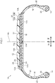
- the tire 10 includes a tire case 17 serving as an example of a circular tire frame member, a belt 12, and a tread 30 formed of a rubber material.
- the tire case 17 of the present exemplary embodiment is configured employing a thermoplastic elastomer serving as an example of a resin material for a tire frame.
- the tire case 17 is formed in a circular shape around a tire circumferential direction.
- the tire case 17 is configured including a pair of bead portions 14 disposed spaced apart from each other in the tire axial direction, a pair of side portions 16 extending from the pair of bead portions 14 toward an outer side in the tire radial direction, and a crown portion 18 coupling together the pair of side portions 16.
- the bead portions 14 are locations that contact a rim (not illustrated in the drawings), and a covering layer 22, described later, is provided at a surface of each of the bead portions 14.
- the side portions 16 form side portions of the tire 10, and curve gently so as to protrude toward outer sides in the tire axial direction on progression from the bead portions 14 toward the crown portion 18.
- the crown portion 18 is a location that couples an outer end in the tire radial direction of one of the side portions 16 and an outer end in the tire radial direction of the other of the side portions 16 together, and supports the tread 30 laid at an outer side in the tire radial direction of the crown portion 18.
- the crown portion 18 has a substantially uniform thickness.
- An outer circumferential surface 18A may be formed with a flat profile in cross-section taken along the tire axial direction, or may have a curving profile bulging toward an outer side in the tire radial direction. Note that the outer circumferential surface 18A of the crown portion 18 of the present exemplary embodiment corresponds to an outer periphery of the tire case 17 to which the belt 12 is provided.
- the tire case 17 is formed by forming a pair of annular tire halves 17H, each including a single bead portion 14, a single side portion 16, and a half-width crown portion 18.
- the tire halves 17H are made to face each other and end portions of the half-width crown portions 18 are bonded together at the tire equatorial plane CL.
- the end portions are bonded together using, for example, a resin welding material 17A.
- An annular bead core 20 extending around the tire circumferential direction is embedded in each of the bead portions 14.
- the bead core 20 is configured from a bead cord (not illustrated in the drawings).
- the bead cord is for example configured by a metal cord such as a steel cord, an organic fiber cord, a resin-covered organic fiber cord, or a hard resin. Note that the bead core 20 itself may be omitted as long as sufficient rigidity of the bead portion 14 can be secured.
- each of the bead portions 14 at least a portion that contacts the rim (not illustrated in the drawings) is disposed with the covering layer 22 in order to increase the airtightness against the rim.
- the covering layer 22 is configured from a material such as a rubber material that is softer and more weather-resistant than the tire case 17.
- the covering layer 22 is folded back from an inner face at an inner side in the tire axial direction of each of the bead portions 14 toward an outer side in the tire axial direction, and extends across an outer face of the side portion 16 to the vicinity of an outer side end portion 12A, in the tire axial direction, of the belt 12.
- the covering layer 22 may be omitted if sealing properties (airtightness) between the bead portion 14 and the rim (not illustrated in the drawings) can be secured by the bead portion 14 of the tire case 17 alone.
- a reinforcing member (polymer or metal fibers, cord, nonwoven fabric, woven fabric, or the like) may be embedded in the tire case 17.
- the belt 12 is a reinforcing layer provided at the outer periphery of the tire case 17.
- the outer periphery of the tire case 17 corresponds to the outer circumferential surface 18A of the crown portion 18.
- a resin-covered cord 28 is wound onto the outer periphery of the tire case 17 in a spiral pattern around the tire circumferential direction and is bonded to the tire case 17, and sections of the resin-covered cord 28 that are mutually adjacent in the tire axial direction are bonded to one another by welding.
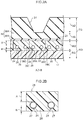
- the resin-covered cord 28 of the present exemplary embodiment is configured by covering two reinforcing cords 24 with a covering resin 26.
- sections of the resin-covered cord 28 that are mutually adjacent in the tire axial direction refers to one side face 28C of the resin-covered cord 28 and another side face 28D of the resin-covered cord 28 being adjacent to each other in the tire axial direction.
- the side faces 28C, 28D are made to oppose each other when winding the resin-covered cord 28 in a spiral pattern.
- the tread 30 formed of a rubber material is laid at the outer side in the tire radial direction of the belt 12. The tread 30 covers the belt 12 from the outer side in the tire radial direction.
- the tread 30 is configured including a tread body rubber layer 30A that contacts the road surface and is formed of a rubber material with excellent anti-wear properties, and a cushioning rubber 30B that is integrally provided at an inner side in the tire radial direction of the tread body rubber layer 30A and that has lower elasticity than the rubber material configuring the tread body rubber layer 30A.
- the cushioning rubber 30B improves ride comfort by absorbing input from the road surface received by the tread body rubber layer 30A during travel of the tire 10. Note that the cushioning rubber 30B may be omitted from the tread 30.
- the rubber materials employed in the tread 30 may be rubber materials that are generally employed in the treads of conventional pneumatic tires.
- a gauge TG of the tread 30 at the outer side in the tire radial direction of the belt 12 is preferably within a range of from 9 mm to 15 mm.
- the tread 30 of the present exemplary embodiment is formed with circumferential direction grooves 31 for drainage on both sides in the width direction of the tire equatorial plane CL.
- a groove depth GD of the circumferential direction grooves 31 is preferably within a range of from 5.5 mm to 9.0 mm, and a dimension tG from the groove bottoms of the circumferential direction grooves 31 to the outer circumferential surface of the belt 12 is preferably within a range of from 1.5 to 3.0 mm.
- the resin-covered cord 28 of the present exemplary embodiment has a rectangular cross-section profile, in other words a rectangular cross-section profile with its length direction along a belt width direction, with the two reinforcing cords 24 arranged in a row along the length direction.
- a thickness A of the covering resin 26 from the reinforcing cords 24 to the outer circumferential surface of the belt 12 is preferably at least 0.1 mm, and is more preferably at least 0.5 mm.
- a thickness B of the covering resin 26 from the reinforcing cords 24 to the tire case 17 is preferably at least 0.05 mm.
- a combined gauge RG of the tire case 17 and the belt 12 is preferably no greater than 3.5 mm.
- a relationship A > B is satisfied, wherein A is the thickness (minimum distance) of the covering resin 26 from the reinforcing cords 24 to the outer circumferential surface of the belt 12 as measured along the thickness direction of the belt 12, and B is the thickness (minimum distance) of the covering resin 26 from the reinforcing cords 24 to the tire case 17 as measured along the thickness direction of the belt 12.
- A is the thickness (minimum distance) of the covering resin 26 from the reinforcing cords 24 to the outer circumferential surface of the belt 12 as measured along the thickness direction of the belt 12
- B is the thickness (minimum distance) of the covering resin 26 from the reinforcing cords 24 to the tire case 17 as measured along the thickness direction of the belt 12.
- the center of each of the reinforcing cords 24 is positioned on a tire case 17 side of a thickness direction intermediate portion of the belt 12. The reinforcing cords 24 are thus further from the tread 30 than from the tire case 17.
- the reinforcing cords 24 may be configured by monofilament (single strand) metal fibers, organic fibers, or the like, or may be configured by multifilaments (twisted strands) by twisting such fibers together.
- the covering resin 26 is, for example, configured by a thermoplastic elastomer. Steel cords configured by twisting together plural steel filaments are employed as the reinforcing cords 24 of the present exemplary embodiment.
- Such filaments may be subjected to surface adhesion processing in order to improve adhesion to the covering resin 26.
- This is surface processing performed to the metal in order to improve adhesion to the thermoplastic material.
- the surface adhesion processing may be organic plating, or surface soaking.
- Organic plating such as the organic electrolytic plating disclosed in Japanese Patent Publication ( JP-B) No. H05-51671 , JP-A No. 2001-1445 , and the like may be employed.
- a bead core B and a reinforcing cord 26A are soaked in an aqueous solution of a water soluble amine compound (or ammonia) for a fixed period of time.
- Hydrazine or a dielectric thereof, a low carbon number amine compound, pyridine, aniline, or the like may be employed as the water soluble amine compound.
- low carbon number amines that are preferably employed include methylamine, dimethylamine, trimethylamine, ethylamine, diethylamine, triethylamine, and the like.
- each of the reinforcing cords 24 is configured including an adhesion layer 27 in order to raise adhesive strength (bonding strength) with the covering resin 26.
- the adhesion layer 27 employs a material that is less readily permeated by moisture than that the covering resin 26, in other words a material that does not readily absorb moisture.
- adhesives employed for the adhesion layer 27 include adhesives containing one or two or more types of thermoplastic resin, such as a denatured olefin-based resin (denatured polyethylene-based resin, denatured polypropylene-based resin, or the like), a polyamide-based resin, a polyurethane-based resin, a polyester-based resin, a denatured polyester-based resin, an ethylene-acrylate ethylcopolymer, or an ethylene-vinyl acetate copolymer, as a main component (main agent).
- a denatured olefin-based resin denatured polyethylene-based resin, denatured polypropylene-based resin, or the like
- a polyamide-based resin such as a polyamide-based resin, a polyurethane-based resin, a polyester-based resin, a denatured polyester-based resin, an ethylene-acrylate ethylcopolymer, or an ethylene-vinyl acetate cop
- a hot melt adhesive containing at least one item selected from the group consisting of a denatured olefin-based resin, a polyester-based resin, a denatured polyester-based resin, an ethylene-ethyl acrylate copolymer, and an ethylene-vinyl acetate copolymer is preferable, a hot melt adhesive containing at least one item selected from the group consisting of a denatured olefin-based resin and a denatured polyester-based resin is more preferable.
- a hot melt adhesive containing at least one item selected from the group consisting of an acid-denatured olefin-based resin and a denatured polyester-based resins is still more preferable, and a hot melt adhesive containing an acid-denatured polyester-based resin is particularly preferable.
- a thickness of the adhesion layer 27 may, for example, be approximately 0.05 mm. This encompasses cases in which the thickness of the adhesion layer 27 is thinner than 0.05 mm and cases in which the thickness of the adhesion layer 27 is thicker than 0.05 mm.
- Resin materials employed for the tire case 17 and the covering resin 26 in the present exemplary embodiment are not limited to thermoplastic elastomers.
- thermoplastic resins, thermosetting resins, and other general purpose resins, as well as engineering plastics (including super engineering plastics) may be employed as the resin materials.
- engineering plastics including super engineering plastics
- the resin materials referred to herein do not include vulcanized rubber.
- Thermoplastic resins are polymer compounds of materials that soften and flow with increased temperature, and that adopt a relatively hard and strong state when cooled.
- thermoplastic elastomers polymer compounds of materials that soften and flow with increasing temperature, that adopt a relatively hard and strong state on cooling, and that have a rubber-like elasticity, considered to be thermoplastic elastomers, and polymer compounds of materials that soften and flow with increasing temperature, that adopt a relatively hard and strong state on cooling, and do not have a rubber-like elasticity, considered to be non-elastomer thermoplastic resins.
- thermoplastic resins include thermoplastic polyolefin-based elastomers (TPO), thermoplastic polystyrene-based elastomers (TPS), thermoplastic polyamide-based elastomers (TPA), thermoplastic polyurethane-based elastomers (TPU), thermoplastic polyester-based elastomers (TPC), and dynamically crosslinking-type thermoplastic elastomers (TPV), as well as thermoplastic polyolefin-based resins, thermoplastic polystyrene-based resins, thermoplastic polyamide-based resins, and thermoplastic polyester-based resins.
- TPO thermoplastic polyolefin-based elastomers
- TPS thermoplastic polystyrene-based elastomers
- TPA thermoplastic polyamide-based elastomers
- TPU thermoplastic polyurethane-based elastomers
- TPC thermoplastic polyester-based elastomers
- TPV dynamically crosslinking-type thermoplastic elasto
- thermoplastic materials have, for example, a deflection temperature under load (at 0.45 MPa during loading), as defined by ISO 75-2 or ASTM D648, of 78°C or greater, a tensile yield strength, as defined by JIS K7113, of 10 MPa or greater, and a tensile elongation at break (JIS K7113), also as defined by JIS K7113, of 50% or greater.
- a deflection temperature under load as defined by ISO 75-2 or ASTM D648, of 78°C or greater
- a tensile yield strength as defined by JIS K7113, of 10 MPa or greater
- JIS K7113 tensile elongation at break
- Materials with a Vicat softening temperature, as defined by JIS K7206 (method A) of 130°C may be employed.
- thermosetting resins are curable polymer compounds that form a 3 dimensional mesh structure with increasing temperature.
- thermosetting resins include phenolic resins, epoxy resins, melamine resins, and urea resins.
- thermoplastic resins including thermoplastic elastomers
- thermosetting resins general purpose resins may also be employed, such as meth(acrylic)-based resins, EVA resins, vinyl chloride resins, fluororesins, and silicone-based resins.
- thermoplastic resin material is injection molded to form a set of the tire halves 17H incorporating the bead cores 20.
- the covering layer 22 is formed at the outer faces of the tire halves 17H.
- the pair of tire halves 17H are made to face each other and end portions of the portions configuring the crown portion 18 are abutted against each other.
- the resin welding material 17A is applied to the abutting portions in a molten state, and the pair of tire halves 17H are bonded together.
- the annular tire case 17 is formed in this manner.
- the tire case 17 is attached to a tire support device (not illustrated in the drawings) that rotatably supports the tire case 17, and as illustrated in Fig. 3 , a cord feeder 40, a heater 50, a press roller 60 serving as a pressing device, and a cooling roller 70 serving as a cooling device are moved to the vicinity of the outer periphery of the tire case 17.
- the cord feeder 40 is configured including a reel 42 onto which the resin-covered cord 28 is wound, and a guide member 44.
- the guide member 44 is used to guide the resin-covered cord 28 unwound from the reel 42 onto the outer periphery of the tire case 17 (the outer circumferential surface 18A of the crown portion 18).
- the guide member 44 is tube shaped and the resin-covered cord 28 passes through an interior of the guide member 44.
- the resin-covered cord 28 is fed out through an opening 46 of the guide member 44 toward the outer circumferential surface 18A of the crown portion 18.
- the heater 50 blows hot air onto the thermoplastic resin, thereby heating and melting portions onto which the hot air is blown.
- the locations onto which the hot air is blown correspond to the inside face 28A of the resin-covered cord 28 to be pressed against the outer circumferential surface 18A of the crown portion 18, and a portion of the outer circumferential surface 18A of the crown portion 18 where the resin-covered cord 28 is to be laid. Note that in cases in which the resin-covered cord 28 has already been wound once or more around the circumference of the outer circumferential surface 18A of the crown portion 18 such that resin-covered cord 28 that has been pressed against the outer circumferential surface 18A is present, the hot air is also blown onto the side face 28C thereof.
- the heater 50 blows out air heated by an electrical heating coil (not illustrated in the drawings) through a blower outlet 52 in an airflow generated by a fan (not illustrated in the drawings).
- an electrical heating coil not illustrated in the drawings
- a blower outlet 52 in an airflow generated by a fan (not illustrated in the drawings).
- the configuration of the heater 50 is not limited to that described above, and any configuration may be applied as long as the thermoplastic resin can be heated and melted.
- a hot iron may be contacted against locations to be melted to heat and melt the contacted portions.
- locations to be melted may be heated and melted using radiant heat, or may be heated and melted by irradiation with infrared radiation.
- the press roller 60 presses the resin-covered cord 28 against the outer periphery of the tire case 17 (the outer circumferential surface 18A of the crown portion 18), and is capable of adjusting the pressing force.
- a roller surface of the press roller 60 is treated so as to prevent molten resin material from adhering thereto.
- the press roller 60 is capable of rotating, and in a state in which the resin-covered cord 28 is being pressed against the outer periphery of the tire case 17, the press roller 60 rotates following the rotation direction of the tire case 17 (arrow C direction).
- the cooling roller 70 is disposed on a downstream side of the press roller 60 in the rotation direction of the tire case 17 (arrow C direction).
- the cooling roller 70 cools the resin-covered cord 28 and cools the crown portion 18 side through the resin-covered cord 28 while pressing the resin-covered cord 28 against the outer periphery of the tire case 17 (the outer circumferential surface 18A of the crown portion 18).
- the pressing force of the cooling roller 70 can be adjusted, and the roller surface is treated so as to prevent molten resin material from adhering thereto.
- the cooling roller 70 is capable of rotating similarly to the press roller 60, and in a state in which the resin-covered cord 28 is being pressed against the outer periphery of the tire case 17, the cooling roller 70 rotates following the rotation direction of the tire case 17 (arrow C direction).
- a liquid for example water
- the cooling roller 70 may be omitted in cases in which the molten resin material is cooled naturally.
- Hot air is blown through the blower outlet 52 of the heater 50, and the inside face 28A of the resin-covered cord 28 is adhered to a molten portion of the crown portion 18 as the inside face 28A of the resin-covered cord 28 and the portion of the crown portion 18 where the resin-covered cord 28 is to be laid are heated and melted.
- the resin-covered cord 28 is then pressed against the outer circumferential surface 18A of the crown portion 18 by the press roller 60. When this is performed, the side faces 28C, 28D of sections of the resin-covered cord 28 that are mutually adjacent in the tire axial direction are also bonded together (see Fig. 2A ).
- the outside face 28B of the resin-covered cord 28 then contacts the cooling roller 70 such that the molten portion of the crown portion 18 and the molten portion of the resin-covered cord 28 are cooled through the resin-covered cord 28 and thereby solidified.
- the resin-covered cord 28 and the crown portion 18 are welded together in this manner.
- the belt 12 is formed at the outer periphery of the tire case 17, specifically, at the outer periphery of the crown portion 18.
- the position of the opening 46 of the cord feeder 40 may be moved in the tire axial direction as the tire case 17 rotates, or the tire case 17 may be moved in the tire axial direction.
- the tire 10 is completed by providing the unvulcanized tread 30 at the outer side in the tire radial direction of the tire case 17 and the belt 12 and performing a vulcanization process.
- a relationship A > B is satisfied, wherein A is the thickness (minimum distance) of the covering resin 26 from the reinforcing cords 24 to the outer circumferential surface of the belt 12, and B is the thickness (minimum distance) of the covering resin 26 from the reinforcing cords 24 to the tire case 17.
- the reinforcing cords 24 are located further from the rubber material configuring the tread 30 than they would be in a case in which the reinforcing cords 24 were laid at the thickness direction intermediate portion of the belt 12.
- moisture in the rubber material configuring the tread 30 may permeate the covering resin 26 of the belt 12.
- the belt 12 employed in the tire 10 of the present exemplary embodiment supposing moisture present in the rubber material were to permeate the covering resin 26, since the reinforcing cords 24 are positioned toward the tire case 17 side away from the tread 30, the distance from the tread 30 to the reinforcing cords 24 is made longer, and moisture is less likely to reach the reinforcing cords 24.
- the reinforcing cords 24 are thus less readily affected by moisture that has permeated from the rubber material.
- the position of the reinforcing cords 24 is separated from the tread 30 within the limited thickness of the belt 12. Accordingly, an increase in the thickness of the belt 12 and an increase in the weight of the belt 12 are avoided.
- the thickness A of the covering resin 26 from the reinforcing cords 24 to the outer circumferential surface of the belt 12 is preferably at least 0.1 mm, and is more preferably at least 0.5 mm in order to suppress the permeation of moisture from the tread side toward the reinforcing cords 24. This effectively enables the reinforcing cords 24 to be less readily affected by moisture permeating from the rubber material configuring the tread 30, enabling corrosion (rusting) of the steel cords configuring the reinforcing cords 24 to be effectively suppressed during actual use.
- the adhesion layer 27 that is less readily permeated by moisture than the covering resin 26 is provided around the outer periphery of the reinforcing cords 24, thereby enabling corrosion (rusting) of the steel cords to be more effectively suppressed than in cases in which an adhesion layer that is readily permeated by moisture is provided.
- the thickness B of the covering resin 26 from the reinforcing cords 24 to the tire case 17 is preferably at least 0.05 mm. This is in order to secure the requisite covering resin 26 at the welding portion (the portion where resin materials of the covering resin 26 and the tire case 17 are welded together) when welding the covering resin 26 of the resin-covered cord 28 and the tire case 17 together.
- the portion of the belt 12 where the covering resin 26 has the thickness B from the reinforcing cords 24 to the tire case 17 corresponds to a welding region to weld the belt 12 to the tire case 17.
- gauge BG of the belt 12 Setting the gauge BG of the belt 12 to at least 1.15 mm enables the preferable lower limit values (0.1 mm and 0.05 mm) of the thickness A and the thickness B to be secured as long as the diameter of the reinforcing cords 24 is no greater than 1.0 mm. Moreover, setting the upper limit of the gauge BG of the belt 12 to 2.0 mm enables reinforcing cords 24 having a diameter larger than 1.0 mm to be employed while still satisfying the preferable lower limit value of the thickness A and the lower limit value of the thickness B.
- the amount of resin employed does not increase more than necessary, enabling a reduction in the weight of the tire 10.
- gauge TG of the tread 30 within a range of from 9 mm to 15 mm in the tire 10 of the present exemplary embodiment enables both the lifespan of the passenger car tire and a reduction in weight to be secured. If the gauge TG of the tread 30 is thinner than 9 mm, the time taken (travel distance) for the tread 30 to reach its wear limit (i.e. when the remaining groove depth of the circumferential direction grooves 31 reaches a dimension defined by safety standards due to wear) is shortened. In other words, the lifespan of the tire is shortened. On the other hand, if the gauge TG of the tread 30 exceeds 15 mm, a reduction in weight becomes difficult to achieve.
- an outer circumferential surface of the belt 12 is covered by a reinforcing member 34A and a reinforcing member 34B in order to reinforce the belt 12.
- the reinforcing member 34A and the reinforcing member 34B overlap each other at a tire equatorial plane CL.
- Outer side portions in the tire width direction of the reinforcing member 34A and the reinforcing member 34B extend to outer sides in the width direction of the belt 12 and cover the outer circumferential surface of the tire case 17.
- the reinforcing member 34A and the reinforcing member 34B are fibrous reinforcing members configured by covering plural fiber cords with rubber, and are what are generally referred to as reinforcement plies or cap layers.
- the reinforcing member 34A, the reinforcing member 34B, and the cushioning rubber 30B are each has a gauge of 1 mm in the tire 10 of the present exemplary embodiment, the respective gauges may be a value other than 1 mm.
- two reinforcing members namely the reinforcing member 34A and the reinforcing member 34B, are employed in the tire 10 of the present exemplary embodiment, three or more reinforcing members may be employed.
- circumferential direction grooves 31 are formed at the tire equatorial plane CL and on both sides in a tire width direction of the tire equatorial plane CL.
- the reinforcing member 34A and the reinforcing member 34B are superimposed on each other in the vicinity of the tire equatorial plane CL of the tread 30, thereby enabling the ability to withstand input of a projection to the tread 30, namely what is referred to as plunger withstand performance, to be improved.
- a dimension from a groove bottom of the circumferential direction groove 31 on the tire equatorial plane CL to an outermost portion of the reinforcing members is preferably within a range of from 1.5 mm to 3.0 mm.
- the belt 12 is covered by two reinforcing members, namely the reinforcing member 34A and the reinforcing member 34B.
- the present invention is not limited thereto, and as illustrated in Fig. 5 , the belt 12 may be covered by a single reinforcing member 36, or, although not illustrated in the drawings, may be covered by three or more reinforcing members.
- the present disclosure is not limited to application to a passenger car, and there is no limitation to the tire to which the present disclosure is applied.
- the present disclosure may be applied to another tire type such as the tires employed in small trucks.
Landscapes
- Engineering & Computer Science (AREA)
- Mechanical Engineering (AREA)
- Tires In General (AREA)
Applications Claiming Priority (2)
| Application Number | Priority Date | Filing Date | Title |
|---|---|---|---|
| JP2017110916A JP2018203062A (ja) | 2017-06-05 | 2017-06-05 | タイヤ |
| PCT/JP2018/015912 WO2018225387A1 (fr) | 2017-06-05 | 2018-04-17 | Pneu |
Publications (2)
| Publication Number | Publication Date |
|---|---|
| EP3636452A1 true EP3636452A1 (fr) | 2020-04-15 |
| EP3636452A4 EP3636452A4 (fr) | 2021-01-20 |
Family
ID=64566590
Family Applications (1)
| Application Number | Title | Priority Date | Filing Date |
|---|---|---|---|
| EP18812916.7A Withdrawn EP3636452A4 (fr) | 2017-06-05 | 2018-04-17 | Pneu |
Country Status (5)
| Country | Link |
|---|---|
| US (1) | US20200101794A1 (fr) |
| EP (1) | EP3636452A4 (fr) |
| JP (1) | JP2018203062A (fr) |
| CN (1) | CN110719850A (fr) |
| WO (1) | WO2018225387A1 (fr) |
Cited By (1)
| Publication number | Priority date | Publication date | Assignee | Title |
|---|---|---|---|---|
| EP4026705B1 (fr) | 2021-01-07 | 2023-05-10 | Sumitomo Rubber Industries, Ltd. | Pneumatique |
Families Citing this family (3)
| Publication number | Priority date | Publication date | Assignee | Title |
|---|---|---|---|---|
| JP7088807B2 (ja) | 2018-10-29 | 2022-06-21 | 京セラ株式会社 | 画像処理装置、カメラ、移動体および画像処理方法 |
| JP2021059312A (ja) * | 2019-10-09 | 2021-04-15 | 株式会社ブリヂストン | タイヤ・ホイール組立体 |
| US20250042201A1 (en) * | 2023-07-31 | 2025-02-06 | The Goodyear Tire & Rubber Company | Non-pneumatic tire |
Family Cites Families (16)
| Publication number | Priority date | Publication date | Assignee | Title |
|---|---|---|---|---|
| BE892858A (fr) * | 1981-04-16 | 1982-08-02 | Pirelli | Pneumatique pour vehicules automobiles a basse absorption de puissance |
| JPH02298284A (ja) | 1989-02-02 | 1990-12-10 | Kunio Mori | 金属表面の電気化学的表面処理法とその複合体 |
| JPH03143701A (ja) * | 1989-10-27 | 1991-06-19 | Sumitomo Rubber Ind Ltd | 空気入りタイヤ |
| JPH05116504A (ja) * | 1991-04-15 | 1993-05-14 | Sumitomo Rubber Ind Ltd | 空気入りタイヤ |
| JP3180166B2 (ja) * | 1992-06-05 | 2001-06-25 | 横浜ゴム株式会社 | 空気入りラジアルタイヤ |
| JP2001001445A (ja) | 1999-06-24 | 2001-01-09 | Toa Denka:Kk | 導電性物体と樹脂との複合体及びその製造方法 |
| JP2001328406A (ja) * | 2000-05-23 | 2001-11-27 | Bridgestone Corp | 空気入りラジアルタイヤ |
| JP4202015B2 (ja) | 2001-12-10 | 2008-12-24 | 大成プラス株式会社 | 金属と樹脂の複合体及びその製造方法 |
| JP2008296865A (ja) * | 2007-06-04 | 2008-12-11 | Bridgestone Corp | 空気入りタイヤ |
| US8413697B2 (en) * | 2011-08-31 | 2013-04-09 | The Goodyear Tire & Rubber Company | Pneumatic tire having a dual layer tread |
| JP6053016B2 (ja) * | 2013-04-18 | 2016-12-27 | 株式会社ブリヂストン | タイヤ |
| WO2014175453A1 (fr) * | 2013-04-25 | 2014-10-30 | 株式会社ブリヂストン | Pneumatique |
| JP6138663B2 (ja) * | 2013-10-29 | 2017-05-31 | 株式会社ブリヂストン | タイヤ |
| JP6452550B2 (ja) * | 2015-05-28 | 2019-01-16 | 株式会社ブリヂストン | タイヤ |
| JP6452549B2 (ja) * | 2015-05-28 | 2019-01-16 | 株式会社ブリヂストン | タイヤ及びその製造方法 |
| JP2017110916A (ja) | 2015-12-14 | 2017-06-22 | 富士電機株式会社 | 劣化診断装置及び劣化診断方法 |
-
2017
- 2017-06-05 JP JP2017110916A patent/JP2018203062A/ja active Pending
-
2018
- 2018-04-17 US US16/616,966 patent/US20200101794A1/en not_active Abandoned
- 2018-04-17 CN CN201880035844.6A patent/CN110719850A/zh active Pending
- 2018-04-17 EP EP18812916.7A patent/EP3636452A4/fr not_active Withdrawn
- 2018-04-17 WO PCT/JP2018/015912 patent/WO2018225387A1/fr not_active Ceased
Cited By (1)
| Publication number | Priority date | Publication date | Assignee | Title |
|---|---|---|---|---|
| EP4026705B1 (fr) | 2021-01-07 | 2023-05-10 | Sumitomo Rubber Industries, Ltd. | Pneumatique |
Also Published As
| Publication number | Publication date |
|---|---|
| JP2018203062A (ja) | 2018-12-27 |
| EP3636452A4 (fr) | 2021-01-20 |
| WO2018225387A1 (fr) | 2018-12-13 |
| US20200101794A1 (en) | 2020-04-02 |
| CN110719850A (zh) | 2020-01-21 |
Similar Documents
| Publication | Publication Date | Title |
|---|---|---|
| EP3530484B1 (fr) | Pneu | |
| EP2987650B1 (fr) | Pneu et son procédé de production | |
| EP2987649B1 (fr) | Pneu et son procédé de production | |
| EP3225425B1 (fr) | Pneu | |
| EP3225424B1 (fr) | Pneumatique | |
| EP3530486B1 (fr) | Pneu | |
| JP6845086B2 (ja) | 空気入りタイヤ | |
| CN110603159B (zh) | 充气轮胎 | |
| EP3636452A1 (fr) | Pneu | |
| EP3290230B1 (fr) | Pneu | |
| EP3290229B1 (fr) | Pneumatique | |
| WO2019225374A1 (fr) | Pneu | |
| WO2021112049A1 (fr) | Fibre, procédé de fabrication de câblé revêtu de résine, et procédé de fabrication de pneu | |
| WO2019244776A1 (fr) | Bandage pneumatique | |
| US20210229500A1 (en) | Resin-covered cord and pneumatic tire | |
| WO2020004064A1 (fr) | Pneumatique | |
| WO2019244721A1 (fr) | Bandage pneumatique | |
| US20210245549A1 (en) | Tire and method of manufacturing belt layer constituent member | |
| JP2021095036A (ja) | 空気入りタイヤ | |
| JP2021091356A (ja) | 空気入りタイヤ | |
| JP2019209761A (ja) | 空気入りタイヤ | |
| CN112203871A (zh) | 缺气保用轮胎 | |
| JP2019217843A (ja) | タイヤ |
Legal Events
| Date | Code | Title | Description |
|---|---|---|---|
| STAA | Information on the status of an ep patent application or granted ep patent |
Free format text: STATUS: THE INTERNATIONAL PUBLICATION HAS BEEN MADE |
|
| PUAI | Public reference made under article 153(3) epc to a published international application that has entered the european phase |
Free format text: ORIGINAL CODE: 0009012 |
|
| STAA | Information on the status of an ep patent application or granted ep patent |
Free format text: STATUS: REQUEST FOR EXAMINATION WAS MADE |
|
| 17P | Request for examination filed |
Effective date: 20191120 |
|
| AK | Designated contracting states |
Kind code of ref document: A1 Designated state(s): AL AT BE BG CH CY CZ DE DK EE ES FI FR GB GR HR HU IE IS IT LI LT LU LV MC MK MT NL NO PL PT RO RS SE SI SK SM TR |
|
| AX | Request for extension of the european patent |
Extension state: BA ME |
|
| DAV | Request for validation of the european patent (deleted) | ||
| DAX | Request for extension of the european patent (deleted) | ||
| A4 | Supplementary search report drawn up and despatched |
Effective date: 20201223 |
|
| RIC1 | Information provided on ipc code assigned before grant |
Ipc: B60C 5/01 20060101AFI20201217BHEP Ipc: B60C 9/22 20060101ALI20201217BHEP Ipc: B60C 11/00 20060101ALI20201217BHEP Ipc: B60C 5/00 20060101ALI20201217BHEP |
|
| STAA | Information on the status of an ep patent application or granted ep patent |
Free format text: STATUS: THE APPLICATION IS DEEMED TO BE WITHDRAWN |
|
| 18D | Application deemed to be withdrawn |
Effective date: 20210730 |