EP3636477A1 - Pumpeneinrichtung mit pumpe, verbrennungsmotor zum antrieb der pumpe und kraftstofftank - Google Patents
Pumpeneinrichtung mit pumpe, verbrennungsmotor zum antrieb der pumpe und kraftstofftank Download PDFInfo
- Publication number
- EP3636477A1 EP3636477A1 EP19201860.4A EP19201860A EP3636477A1 EP 3636477 A1 EP3636477 A1 EP 3636477A1 EP 19201860 A EP19201860 A EP 19201860A EP 3636477 A1 EP3636477 A1 EP 3636477A1
- Authority
- EP
- European Patent Office
- Prior art keywords
- fuel
- pump
- tank
- combustion engine
- pump device
- Prior art date
- Legal status (The legal status is an assumption and is not a legal conclusion. Google has not performed a legal analysis and makes no representation as to the accuracy of the status listed.)
- Granted
Links
Images
Classifications
-
- F—MECHANICAL ENGINEERING; LIGHTING; HEATING; WEAPONS; BLASTING
- F02—COMBUSTION ENGINES; HOT-GAS OR COMBUSTION-PRODUCT ENGINE PLANTS
- F02M—SUPPLYING COMBUSTION ENGINES IN GENERAL WITH COMBUSTIBLE MIXTURES OR CONSTITUENTS THEREOF
- F02M37/00—Apparatus or systems for feeding liquid fuel from storage containers to carburettors or fuel-injection apparatus; Arrangements for purifying liquid fuel specially adapted for, or arranged on, internal-combustion engines
- F02M37/0076—Details of the fuel feeding system related to the fuel tank
- F02M37/0088—Multiple separate fuel tanks or tanks being at least partially partitioned
-
- F—MECHANICAL ENGINEERING; LIGHTING; HEATING; WEAPONS; BLASTING
- F02—COMBUSTION ENGINES; HOT-GAS OR COMBUSTION-PRODUCT ENGINE PLANTS
- F02M—SUPPLYING COMBUSTION ENGINES IN GENERAL WITH COMBUSTIBLE MIXTURES OR CONSTITUENTS THEREOF
- F02M37/00—Apparatus or systems for feeding liquid fuel from storage containers to carburettors or fuel-injection apparatus; Arrangements for purifying liquid fuel specially adapted for, or arranged on, internal-combustion engines
- F02M37/0047—Layout or arrangement of systems for feeding fuel
-
- F—MECHANICAL ENGINEERING; LIGHTING; HEATING; WEAPONS; BLASTING
- F02—COMBUSTION ENGINES; HOT-GAS OR COMBUSTION-PRODUCT ENGINE PLANTS
- F02M—SUPPLYING COMBUSTION ENGINES IN GENERAL WITH COMBUSTIBLE MIXTURES OR CONSTITUENTS THEREOF
- F02M37/00—Apparatus or systems for feeding liquid fuel from storage containers to carburettors or fuel-injection apparatus; Arrangements for purifying liquid fuel specially adapted for, or arranged on, internal-combustion engines
- F02M37/02—Feeding by means of suction apparatus, e.g. by air flow through carburettors
- F02M37/025—Feeding by means of a liquid fuel-driven jet pump
-
- F—MECHANICAL ENGINEERING; LIGHTING; HEATING; WEAPONS; BLASTING
- F02—COMBUSTION ENGINES; HOT-GAS OR COMBUSTION-PRODUCT ENGINE PLANTS
- F02M—SUPPLYING COMBUSTION ENGINES IN GENERAL WITH COMBUSTIBLE MIXTURES OR CONSTITUENTS THEREOF
- F02M37/00—Apparatus or systems for feeding liquid fuel from storage containers to carburettors or fuel-injection apparatus; Arrangements for purifying liquid fuel specially adapted for, or arranged on, internal-combustion engines
- F02M37/04—Feeding by means of driven pumps
- F02M37/08—Feeding by means of driven pumps electrically driven
Definitions
- the invention relates to a pump device with a pump, in particular a fire pump, an internal combustion engine for driving the pump and a fuel tank, which is connected to the internal combustion engine via a fuel line, in the course of which a fuel pump for conveying fuel from the fuel tank to the internal combustion engine is switched on.
- Portable versions of such pump devices are also referred to as portable pumps, which can be carried to the respective location and are not permanently installed in a vehicle, in particular a fire engine.
- a fire-fighting centrifugal pump is used as the pump of such portable pumps, which can be driven by an internal combustion engine located on board the portable pump.
- portable pumps have the advantage that they can be used for removing water from open waters away from the emergency vehicle.
- Fuel tanks of portable pumps are designed for self-sufficient operation for one hour at the nominal point. Refueling is required to enable further operation. this happens in the fire service area with standard fuel canisters. For safety reasons, the water supply must be interrupted and the engine switched off. Escaping fuel vapors and an overfilling of fuel can also be in the parked state, for. B. with hot engine components lead to dangers or environmental pollution.
- the object is therefore to create a pump device of the type mentioned at the outset which, in comparison with conventional pump devices, can be operated for longer without interruptions and thus more reliably.
- the aforementioned disadvantages from the prior art are to be avoided.
- the pump device is characterized in that a return line leading to the fuel tank branches off from a line branch of the fuel line between the fuel pump and the internal combustion engine, in the course of which a jet pump is switched on, the suction connection of which for sucking fuel from a fuel replacement tank separate from the fuel tank with the Fuel replacement tank can be coupled or coupled.
- the fuel returned via the return line thus acts as a propellant for the jet pump and ensures that fuel is drawn in from the replacement fuel tank. It is possible to refuel during the operation of the pump device. It is therefore no longer necessary to switch off the internal combustion engine and thus interrupt the water supply. This is a decisive advantage, particularly when fighting fires.
- the jet pump has a Venturi nozzle.
- the Venturi nozzle is a relatively simple component, which is therefore relatively inexpensive.
- the Venturi nozzle is also reliable and relatively low-maintenance.
- the jet pump expediently has a jet pump housing, with a propellant inlet and a propellant outlet, fuel being used as the propellant.
- the pump filing is designed to be portable.
- the portable pump submission is expediently a portable pump.
- the invention would also be applicable to built-in pumps, for example those that are installed in an emergency vehicle.
- a pressure control valve for regulating the fuel pressure for the engine is switched on upstream of the return line.
- the fuel pressure for the rail of the engine can be regulated by the pressure control valve.
- the excess fuel that is not required for the engine is used as the drive medium for the jet pump.
- a shut-off valve for shutting off the suction port when the fuel replacement tank is disconnected is arranged on the suction port. This prevents fuel from escaping via the suction connection when the fuel replacement tank is disconnected.
- the suction connection has a coupling interface to which the fuel replacement tank can be detachably coupled, in particular with the interposition of a suction line.
- the shut-off valve is particularly preferably designed to be self-closing and assumes a shut-off position as soon as the fuel replacement tank is disconnected. A proactive switching of the shut-off valve into the shut-off position is not necessary in this embodiment, since the shut-off valve, in particular its valve member, is automatically transferred into the shut-off position when the fuel replacement tank is uncoupled.
- a fuel filter is switched on in the fuel line.
- the fuel filter is expediently located in the line branch between the fuel pump and the internal combustion engine.
- a level indicator and / or a level measuring device are particularly preferably assigned to the fuel tank. This allows the level of the fuel tank to be checked and the refilling process to be initiated in good time.
- the replacement fuel tank could remain coupled to the suction connection of the jet pump and for a refilling process to be initiated automatically as soon as the level falls below a certain level.
- the shut-off valve can then be designed in such a way that overfilling of the fuel tank with fuel is prevented by shutting off at a certain maximum fill level.
- continuous refilling would also be conceivable, in such a way that fuel, albeit with a significantly lower flow rate, is always returned via the refill line and the jet pump is therefore always in operation and sucks fuel from the fuel replacement canister, whereby the fuel level remains constant until the fuel replacement tank is empty.
- the pump device comprises a fuel replacement tank, in particular in the form of a fuel canister.
- the invention further comprises an emergency vehicle, in particular a fire engine, characterized by a pump device according to one of claims 1 to 11.
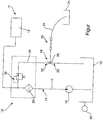
- the figure shows a preferred embodiment of the pump device 11 according to the invention.
- the main component of the pump device 11 is a pump 12, which is described below by way of example in the form of a fire-fighting centrifugal pump.
- the pump device 11 is described by way of example using a portable pump device 11 in the form of a so-called portable pump. In principle, however, it would also be possible to use the pump device as a built-in pump, where it is then installed on board an emergency vehicle, in particular a fire engine.
- the fire-fighting centrifugal pump which for the sake of simplicity is simply referred to as pump 12, has a pump housing (not shown) which encloses a pump chamber.
- a pump rotor (not shown) movably recorded.
- a radial impeller is expediently used as the pump rotor, which is driven by an output part, in particular an output shaft, of an internal combustion engine 13 located on board the portable pump.
- the pump rotor sucks water or, if applicable, a water / foam mixture into the pump chamber via a suction side and releases the suctioned water via a pressure side, ie in the radial direction in the case of a radial impeller, with increased pressure.
- a pressure side ie in the radial direction in the case of a radial impeller, with increased pressure.
- On the pressure side as a rule, several fire hoses can be connected, at the free ends of which jet pipes are attached, by means of which fire-fighting water can be brought to the source of the fire in a targeted manner to fight the fire.
- the internal combustion engine 13 can be a gasoline engine or a diesel engine.
- the internal combustion engine is connected to a fuel tank 15 via a fuel line 14.
- the fuel tank 15 is located on board the portable pump or the portable pump device 11.
- a fuel pump 16 for delivering fuel, that is to say diesel or gasoline, from the fuel tank 15 to the internal combustion engine 13 is switched on.
- a return line 18 leading to the fuel tank 15 is branched off from a line branch 17 of the fuel line 14 between the fuel pump 16 and the internal combustion engine 13, in the course of which a jet pump 19 is switched on, the suction connection 20 thereof for sucking fuel from a position of the fuel tank 15 separate fuel replacement tank 21 can be coupled or coupled to the fuel replacement tank 21.
- the jet pump shown schematically by way of example in the figure has a Venturi nozzle as its main component.
- a jet pump 19 with a venturi nozzle is relatively inexpensive since it is constructed from a few components.
- the jet pump 19 further comprises a jet pump housing (not shown) which has a propellant inlet 22 and a propellant outlet 23. Fuel flowing back in the return line 18 in the direction of the fuel tank 15 serves as the propellant.
- the fuel replacement tank which is expediently a fuel canister with the suction connection 20 of FIG Jet pump coupled.
- a suction line 24, for example a suction hose, is expediently used for this purpose.
- a shut-off valve 25 is also assigned to the suction connection 20, with which the suction connection 20 can be shut off when the fuel replacement tank 21 is disconnected.
- the suction connection 20 of the jet pump 19 has a coupling interface 26, to which the suction line 24, which leads to the fuel replacement tank 21, is detachably fastened.
- shut-off valve 25 is designed to be self-closing and assumes a shut-off position as soon as the fuel replacement tank 21 is disconnected.
- a pressure control valve 28 for regulating the fuel pressure in the return line 18 is switched on in the return line 18.
- a pressure control valve 28 is selected, the valve member of which is spring-loaded and which opens from a certain presettable or preset pressure.
- the pressure on the primary side of the valve is determined and applied to the valve member in such a way that the valve closes partially if the primary pressure is too high and opens further if the primary pressure is too low.
- the pressure can be varied so that the fuel pressure in the return line can be regulated. Excess fuel that is not required is required to operate the jet pump.
- a fuel filter 29 is switched on in the line branch 17 between the fuel pump 16 and in the internal combustion engine 13.
- a fill level indicator 30 or a fill level measuring device is assigned in the fuel tank 15.
- the fuel pump 16 draws fuel from the fuel tank 15 and presses it on the pressure side via the fuel filter 29 through the fuel line 14 to the internal combustion engine 13, where fuel is then used to operate the internal combustion engine.
- the fire-fighting centrifugal pump on board the portable pump is driven via the internal combustion engine and its output shaft, which in turn draws in extinguishing water on the suction side and releases it on the pressure side.
- the fill level of fuel in the fuel tank 15 can be checked via the fill level indicator 30. If the fill level of the fuel falls below a minimum value, there is a need to refill the fuel tank 15, i. H. refuel. If necessary, this can be determined via an acoustic and / or optical signal.
- the fuel canister is coupled to the coupling interface 26 via the suction line 24, the shut-off valve 25 being switched to the open position.
- the jet pump 19, which in turn draws fuel from the fuel canister and supplies it to the fuel tank 15, is operated via fuel returning in the return line 18.
- the shut-off valve 25 can be designed in such a way that overfilling of the fuel tank 15 is prevented by closing at a certain fill level.
- the fuel replacement tank 21, in particular the fuel canister in operation is coupled to the suction connection 20 of the jet pump via the suction line 24, so that fuel is automatically and always conveyed from the fuel canister into the fuel tank, as a result of which the fill level of the fuel in the fuel tank 15 is increased a certain time until the fuel canister is essentially constant.
Landscapes
- Engineering & Computer Science (AREA)
- Chemical & Material Sciences (AREA)
- Combustion & Propulsion (AREA)
- Mechanical Engineering (AREA)
- General Engineering & Computer Science (AREA)
- Cooling, Air Intake And Gas Exhaust, And Fuel Tank Arrangements In Propulsion Units (AREA)
- Jet Pumps And Other Pumps (AREA)
Abstract
Description
- Die Erfindung betrifft eine Pumpeneinrichtung, mit einer Pumpe, insbesondere Feuerlöschpumpe, einem Verbrennungsmotor zum Antrieb der Pumpe und einem Kraftstofftank, der mit dem Verbrennungsmotor über eine Kraftstoffleitung verbunden ist, in deren Verlauf eine Kraftstoffpumpe zur Förderung von Kraftstoff aus dem Kraftstofftank zum Verbrennungsmotor eingeschaltet ist.
- Pumpeneinrichtungen dieser Art sind bereits seit langem bekannt. Tragbare Ausführungen solcher Pumpeneinrichtungen werden auch als Tragkraftspritzen bezeichnet, die zum jeweiligen Ort getragen werden können und nicht in einem Fahrzeug, insbesondere Feuerwehrfahrzeug, fest eingebaut sind. In der Regel wird als Pumpe derartiger Tragkraftspritzen eine Feuerlöschkreiselpumpe verwendet, die durch einen an Bord der Tragkraftspritze befindlichen Verbrennungsmotor antreibbar ist. Derartige Tragkraftspritzen haben den Vorteil, dass sie entfernt vom Einsatzfahrzeug zur Wasserentnahme aus offenen Gewässern verwendet werden können.
- Kraftstofftanks von Tragkraftspritzen sind auf autarken Betrieb für eine Stunde im Nennpunkt ausgelegt. Um einen weiteren Betrieb zu ermöglichen muss nachgetankt werden. Dies geschieht im Feuerwehrbereich mit standardmäßigen Kraftstoffkanistern. Aus sicherheitstechnischen Gründen muss dazu die Wasserversorgung unterbrochen und der Motor abgestellt werden. Entweichende Kraftstoffdämpfe sowie eine Überfüllung von Kraftstoff können auch im abgestellten Zustand z. B. bei heißen Motorkomponenten zu Gefahren bzw. Umweltbelastungen führen.
- Aufgabe ist es daher, eine Pumpeneinrichtung der eingangs erwähnten Art zu schaffen, die im Vergleich zu herkömmlichen Pumpeneinrichtungen länger ohne Unterbrechungen und damit sicherer betreibbar ist. Insbesondere sollen die vorgenannten Nachteile aus dem Stand der Technik vermieden werden.
- Diese Aufgabe wird durch eine Pumpeneinreichung mit den Merkmalen des unabhängigen Anspruchs 1 gelöst. Weiterbildungen der Erfindung sind in den Unteransprüchen dargestellt.
- Die erfindungsgemäße Pumpeneinrichtung zeichnet sich dadurch aus, dass von einem Leitungsast der Kraftstoffleitung zwischen der Kraftstoffpumpe und dem Verbrennungsmotor eine zum Kraftstofftank führende Rücklaufleitung abzweigt, in deren Verlauf eine Strahlpumpe eingeschaltet ist, deren Sauganschluss zum Ansaugen von Kraftstoff aus einem bezüglich des Kraftstofftanks separaten Kraftstoffersatztank mit dem Kraftstoffersatztank koppelbar oder gekoppelt ist.
- Der über die Rücklaufleitung zurückgeführte Kraftstoff wirkt also als Treibmedium für die Strahlpumpe und sorgt für ein Ansaugen von Kraftstoff aus dem Kraftstoffersatztank. Es ist möglich, während des Betriebs der Pumpeneinrichtung nachzutanken. Es ist also nicht mehr notwendig, den Verbrennungsmotor abzustellen und damit die Wasserversorgung zu unterbrechen. Insbesondere bei der Brandbekämpfung ist dies ein entscheidender Vorteil.
- In besonders bevorzugter Weise weist die Strahlpumpe eine Venturi-Düse auf. Die Venturi-Düse ist ein relativ einfach aufgebautes Bauteil, das daher relativ kostengünstig ist. Ferner ist die Venturi-Düse zuverlässig und relativ wartungsarm.
- Zweckmäßigerweise weist die Strahlpumpe ein Strahlenpumpengehäuse auf, mit einem Treibmitteleinlass und einem Treibmittelauslass, wobei als Treibmittel Kraftstoff verwendet wird.
- In besonders bevorzugter Weise ist die Pumpeneinreichung tragbar ausgebildet. Zweckmäßigerweise handelt es sich bei der tragebaren Pumpeneinreichung um eine Tragkraftspritze.
- Die Erfindung wäre jedoch auch auf Einbaupumpen anwendbar, beispielsweise solche die in einem Einsatzfahrzeug eingebaut sind.
- Bei einer Weiterbildung der Erfindung ist vor der Rücklaufleitung ein Druckregelventil zur Regelung des Kraftstoffdrucks für den Motor eingeschaltet. Durch das Druckregelventil lässt sich der Kraftstoffdruck für das Rail des Motors regeln. Der überschüssige Kraftstoff, der für den Motor nicht benötigt wird, wird als Treibmedium für die Strahlpumpe verwendet.
- In besonders bevorzugter Weise ist am Sauganschluss ein Absperrventil zur Absperrung des Sauganschlusses bei abgekoppelten Kraftstoffersatztank angeordnet. Dadurch wird verhindert, dass bei abgekoppelten Kraftstoffersatztank Kraftstoff über den Sauganschluss austreten kann.
- In besonders bevorzugter Weise weist der Sauganschluss eine Kopplungs-Schnittstelle auf, an der der Kraftstoffersatztank insbesondere unter Zwischenschaltung einer Saugleitung lösbar ankoppelbar ist.
- Besonders bevorzugt ist das Absperrventil selbstschließend ausgebildet und nimmt eine Absperrstellung ein, sobald der Kraftstoffersatztank abgekoppelt ist. Ein pro aktives Schalten des Absperrventils in die Absperrstellung ist bei dieser Ausgestaltung nicht notwendig, da das Absperrventil, insbesondere dessen Ventilglied bei Abkopplung des Kraftstoffersatztanks automatisch in die Absperrstellung überführt wird.
- Bei einer Weiterbildung der Erfindung ist in die Kraftstoffleitung ein Kraftstofffilter eingeschaltet. Zweckmäßigerweise befindet sich der Kraftstofffilter im Leitungsast zwischen Kraftstoffpumpe und Verbrennungsmotor.
- Besonders bevorzugt sind dem Kraftstofftank eine Füllstandsanzeige und/oder eine Füllstandsmesseinrichtung zugeordnet. Dadurch lässt sich der Füllstand des Kraftstofftanks kontrollieren und rechtzeitig der Nachfüllvorgang einleiten.
- Es wäre beispielsweise auch möglich, dass der Kraftstoffersatztank an den Sauganschluss der Strahlpumpe angekoppelt bleibt und dann automatisch einen Nachfüllvorgang eingeleitet wird, sobald ein bestimmter Füllstand unterschritten wird. Das Absperrventil kann dann derart ausgestaltet sein, dass ein Überfüllen des Kraftstofftanks mit Kraftstoff verhindert wird, indem es bei einem bestimmten Maximal-Füllstand absperrt. Ferner wäre auch ein kontinuierliches Nachfüllen denkbar, in derart, dass stets Kraftstoff, wenngleich mit deutlich geringerem Durchfluss, über die Nachüllleitung rückgeführt wird und daher die Strahlpumpe stets in Betrieb ist und Kraftstoff aus dem Kraftstoffersatzkanister ansaugt, wodurch der Füllstand an Kraftstoff solange konstant bleibt bis der Kraftstoffersatztank leer ist.
- Bei einer Weiterbildung der Erfindung umfasst die Pumpeneinrichtung einen Kraftstoffersatztank, insbesondere in Form eines Kraftstoffkanisters.
- Die Erfindung umfasst ferner ein Einsatzfahrzeug, insbesondere Feuerwehrfahrzeug, gekennzeichnet durch eine Pumpeneinrichtung nach einem der Ansprüche 1 bis 11.
- Ein bevorzugtes Ausführungsbeispiel ist in der Zeichnung dargestellt und wird im Folgenden näher erläutert. Die einzige Figur der Zeichnung zeigt:
eine schematische Darstellung eines bevorzugten Ausführungsbeispiels der erfindungsgemäßen Pumpeneinrichtung. - Die Figur zeigt ein bevorzugtes Ausführungsbeispiel der erfindungsgemäßen Pumpeneinrichtung 11. Hauptkomponente der Pumpeneinrichtung 11 ist eine Pumpe 12, die im Folgenden beispielhaft in Form einer Feuerlöschkreiselpumpe beschrieben ist. Die Pumpeneinrichtung 11 wird beispielhaft an Hand einer portablen Pumpeneinrichtung 11 in Form einer sogenannten Tragkraftspritze beschrieben. Prinzipiell wäre es jedoch auch möglich, die Pumpeneinrichtung als Einbaupumpe zu verwenden, wo sie dann an Bord eines Einsatzfahrzeugs, insbesondere Feuerwehrfahrzeug, eingebaut ist.
- Die Feuerlöschkreiselpumpe, die im Folgenden der Einfachheit halber lediglich als Pumpe 12 bezeichnet wird, besitzt ein Pumpengehäuse (nicht dargestellt), das einen Pumpenraum umschließt. Im Pumpenraum ist ein Pumpenläufer (nicht dargestellt) beweglich aufgenommen. Als Pumpenläufer wird zweckmäßigerweise ein Radiallaufrad verwendet, das von einem Abtriebsteil, insbesondere Abtriebswelle, eines an Bord der Tragkraftspritze befindlichen Verbrennungsmotors 13 angetrieben wird.
- Der Pumpenläufer saugt im Betrieb Wasser oder ggf. ein Wasser-/ Schaumgemisch über eine Saugseite in den Pumpenraum und gibt das angesaugte Wasser über eine Druckseite, im Falle eines Radiallaufrads also in radialer Richtung, mit erhöhtem Druck ab. An der Druckseite sind in der Regel mehrere Feuerwehrschläuche anschließbar, an deren freien Enden Strahlrohre befestigt sind, über die Löschwasser gezielt zur Brandbekämpfung an den Brandherd gebracht werden kann.
- Bei dem Verbrennungsmotor 13 kann es sich um einen Ottomotor oder einen Dieselmotor handeln.
- Der Verbrennungsmotor ist über eine Kraftstoffleitung 14 mit einem Kraftstofftank 15 verbunden. Der Kraftstofftank 15 befindet sich an Bord der Tragkraftspritze bzw. der tragbaren Pumpeneinrichtung 11.
- In den Verlauf der Kraftstoffleitung 14 ist eine Kraftstoffpumpe 16 zur Förderung von Kraftstoff, also Diesel oder Benzin aus dem Kraftstofftank 15 zum Verbrennungsmotor 13 eingeschaltet.
- Zum Betreiben des Verbrennungsmotors 13 wird Kraftstoff mittels der Kraftstoffpumpe 16 dem Verbrennungsmotor 13 über die Kraftstoffleitung 14 zugeführt. Dies hat zur Folge, dass sich der Füllstand des Kraftstoffs im Kraftstofftank 15 verringert. Bei herkömmlichen Tragkraftspritzen besteht der Bedarf, einen niedrigen Füllstand des Kraftstoffs in dem Kraftstofftank 15 derart rechtzeitig zu erkennen, dass sich der Kraftstofftank 15 nicht vollständig leert, was zur Folge hätte, dass Luft angesaugt wird und möglicherweise die Kraftstoffpumpe beschädigt wird. Ferner würde der Betrieb des Verbrennungsmotors und somit die Wasserversorgung unterbrochen werden.
- Bei herkömmlichen Tragkraftspritzen war daher ein rechtzeitiges Nachtanken erforderlich. Hierzu musste der Verbrennungsmotor abgeschaltet werden, was zur Folge hatte, dass die Wasserversorgung unterbrochen wird.
- Bei der erfindungsgemäßen Pumpeneinrichtung 11 ist hingegen von einem Leitungsast 17 der Kraftstoffleitung 14 zwischen der Kraftstoffpumpe 16 und dem Verbrennungsmotor 13 eine zum Kraftstofftank 15 führende Rücklaufleitung 18 abgezweigt, in deren Verlauf eine Strahlpumpe 19 eingeschaltet ist, deren Sauganschluss 20 zum Ansaugen von Kraftstoff aus einem bezüglich des Kraftstofftanks 15 separaten Kraftstoffersatztank 21 mit dem Kraftstoffersatztank 21 koppelbar oder gekoppelt ist.
- Die in der Figur beispielhaft schematisch dargestellte Strahlpumpe weist als Hauptbestandteil eine Venturi-Düse auf. Eine derartige Strahlpumpe 19 mit Venturi-Düse ist relativ kostengünstig, da sie aus wenigen Bauteilen aufgebaut ist. Die Strahlpumpe 19 umfasst ferner ein Strahlpumpengehäuse (nicht dargestellt), das einen Treibmitteleinlass 22 und einen Treibmittelauslass 23 aufweist. Als Treibmittel dient in der Rücklaufleitung 18 in Richtung Kraftstofftank 15 zurückströmender Kraftstoff.
- Wie beispielhaft in der Figur dargestellt, ist der Kraftstoffersatztank, bei dem es sich zweckmäßigerweise um einen Kraftstoffkanister handelt mit dem Sauganschluss 20 der Strahlpumpe gekoppelt. Zweckmäßigerweise wird hierfür eine Saugleitung 24, beispielsweise Saugschlauch, verwendet.
- Dem Sauganschluss 20 ist ferner ein Absperrventil 25 zugeordnet, mit dem der Sauganschluss 20 bei abgekoppeltem Kraftstoffersatztank 21 absperrbar ist. Im gezeigten Beispielsfall weist der Sauganschluss 20 der Strahlpumpe 19 eine Kopplungs-schnittstelle 26 auf, an der die Saugleitung 24, die zum Kraftstoffersatztank 21 führt, lösbar befestigt ist.
- Das Absperrventil 25 ist im gezeigten Beispielsfall selbstschließend ausgebildet und nimmt eine Absperrstellung ein, sobald der Kraftstoffersatztank 21 abgekoppelt ist.
- Wie insbesondere schematisch in der Figur gezeigt, ist in die Rücklaufleitung 18 ein Druckregelventil 28 zur Regelung des Kraftstoffdrucks in der Rücklaufleitung 18 eingeschaltet. Im gezeigten Beispielsfall ist ein Druckregelventil 28 gewählt, dessen Ventilglied federbelastet ist und das ab einen bestimmten voreinstellbaren oder voreingestellten Druck öffnet. Der Druck an der Primärseite des Ventils wird ermittelt und dem Ventilglied aufgeschaltet, in der Art, dass das Ventil bei zu hohem Primärdruck ggf. teilweise schließt und bei zu niedrigem Primärdruck weiter öffnet. Durch Änderung der Federvorspannung der Feder, lässt sich der Druck variieren, so dass der Kraftstoffdruck in der Rücklaufleitung geregelt werden kann. Überschüssiger, nicht benötigter Kraftstoff wird zum Betrieb der Strahlpumpe benötigt.
- Wie ferner schematisch in der Figur gezeigt, ist im Leitungsast 17 zwischen der Kraftstoffpumpe 16 und im Verbrennungsmotor 13 ein Kraftstofffilter 29 eingeschaltet.
- Um den Füllstand des Kraftstofftanks 15 zu überwachen ist im Kraftstofftank 15 eine Füllstandsanzeige 30 oder eine Füllstandsmesseinrichtung zugeordnet.
- Im Betrieb der Tragkraftspritze saugt die Kraftstoffpumpe 16 Kraftstoff aus dem Kraftstofftank 15 an und drückt diesen druckseitig über den Kraftstofffilter 29 durch die Kraftstoffleitung 14 zum Verbrennungsmotor 13, wo dann Kraftstoff zum Betrieb des Verbrennungsmotors verbraucht wird. Über den Verbrennungsmotor und dessen Abtriebswelle ist die an Bord der Tragkraftspritze befindliche Feuerlöschkreiselpumpe angetrieben, die ihrerseits saugseitig Löschwasser ansaugt und druckseitig abgibt. Über die Füllstandsanzeige 30 lässt sich der Füllstand an Kraftstoff im Kraftstofftank 15 kontrollieren. Fällt der Füllstand des Kraftstoffs unter einem Minimalwert, so besteht der Bedarf den Kraftstofftank 15 wieder aufzufüllen, d. h. nachzutanken. Gegebenenfalls lässt sich das über ein akustisches und/oder optisches Signal feststellen. In diesem Fall wird der Kraftstoffkanister an der Kopplungs-Schnittstelle 26 über die Saugleitung 24 angekoppelt, wobei das Absperrventil 25 in die Offenstellung geschaltet wird. Über in der Rücklaufleitung 18 zurücklaufenden Kraftstoff wird die Strahlpumpe 19 betrieben, die ihrerseits Kraftstoff aus dem Kraftstoffkanister ansaugt und dem Kraftstofftank 15 zuführt. Das Absperrventil 25 kann derart ausgestaltet sein, dass ein Überfüllen des Kraftstofftanks 15 verhindert wird, indem es ab einem bestimmten Füllstand schließt.
- Eine andere Variante ist, dass der Kraftstoffersatztank 21 insbesondere der Kraftstoffkanister in Betrieb über die Saugleitung 24 an den Sauganschluss 20 der Strahlpumpe angekoppelt ist, so dass automatisch und stets Kraftstoff vom Kraftstoffkanister in den Kraftstofftank befördert wird, wodurch die Füllhöhe des Kraftstoffs im Kraftstofftank 15 über eine gewisse Zeit, bis der Kraftstoffkanister geleert ist, im Wesentlichen konstant bleibt.
- Bei beiden Betriebsweisen ist es nicht notwendig, den Verbrennungsmotor abzuschalten und damit die Wasserversorgung zu unterbrechen, sondern es kann in Betrieb nachgetankt werden.
Claims (12)
- Pumpeneinrichtung, mit einer Pumpe (12), insbesondere Feuerlöschpumpe, einem Verbrennungsmotor (13) zum Antrieb der Pumpe (12) und einem Kraftstofftank (15), der mit dem Verbrennungsmotor (13) über eine Kraftstoffleitung (14) verbunden ist, in deren Verlauf eine Kraftstoffpumpe (16) zur Förderung von Kraftstoff aus dem Kraftstofftank (15) zum Verbrennungsmotor (13) eingeschaltet ist, dadurch gekennzeichnet, dass von einem Leitungsast (17) der Kraftstoffleitung (14) zwischen der Kraftstoffpumpe (16) und dem Verbrennungsmotor (13) eine zum Kraftstofftank (15) führende Rücklaufleitung (18) abzweigt, in deren Verlauf eine Strahlpumpe (19) eingeschaltet ist, deren Sauganschluss (20) zum Ansaugen von Kraftstoff aus einem bezüglich des Kraftstofftanks (15) separaten Kraftstoffersatztank (21) mit dem Kraftstoffersatztank (21) koppelbar oder gekoppelt ist.
- Pumpeneinrichtung nach Anspruch 1, dadurch gekennzeichnet, dass die Strahlpumpe (19) eine Venturi-Düse aufweist.
- Pumpeneinrichtung nach Anspruchs 1 oder 2, dadurch gekennzeichnet, dass Pumpeneinrichtung (11) tragbar ausgebildet ist.
- Pumpeneinrichtung nach Anspruch 3, dadurch gekennzeichnet, dass es sich bei der tragbaren Pumpeneinrichtung (11) um eine Tragkraftspritze handelt.
- Pumpeneinrichtung nach einem der vorhergehenden Ansprüche, dadurch gekennzeichnet, dass in die Rücklaufleitung (18) ein Druckregelventil (28) zur Regelung des Kraftstoffdrucks für den Verbrennungsmotor (13) eingeschaltet ist.
- Pumpeneinrichtung nach einem der vorhergehenden Ansprüche, dadurch gekennzeichnet, dass am Sauganschluss (20) ein Absperrventil (25) zur Absperrung des Sauganschlusses (20) bei abgekoppelten Kraftstoffersatztank (21) angeordnet ist.
- Pumpeneinrichtung nach einem der vorhergehenden Ansprüche, dadurch gekennzeichnet, dass der Sauganschluss (20) eine Kopplungs-Schnittstelle (27) aufweist, an der der Kraftstoffersatztank (21) insbesondere unter Zwischenschaltung einer Saugleitung (24) lösbar ankoppelbar ist.
- Pumpeneinrichtung nach einem der Ansprüche 6 oder 7, dadurch gekennzeichnet, dass das Absperrventil (25) selbstschließend ausgebildet ist und eine Absperrstellung einnimmt sobald der Kraftstoffersatztank (21) abgekoppelt ist.
- Pumpeneinrichtung nach einem der vorhergehenden Ansprüche, dadurch gekennzeichnet, dass in die Kraftstoffleitung ein Kraftstofffilter (29) eingeschaltet ist, insbesondere im Leitungsast (17) zwischen Kraftstoffpumpe (16) und Verbrennungsmotor (13).
- Pumpeneinrichtung nach einem der vorhergehenden Ansprüche, dadurch gekennzeichnet, dass dem Kraftstofftank (15) eine Füllstandsanzeige (30) und/oder eine Füllstandsmesseinrichtung zugeordnet ist.
- Pumpeneinrichtung nach einem der vorhergehenden Ansprüche, gekennzeichnet durch einen Kraftstoffersatztank (21), insbesondere Kraftstoffkanister.
- Einsatzfahrzeug, insbesondere Feuerwehrfahrzeug, gekennzeichnet durch eine Pumpeneinrichtung (11) nach einem der vorhergehenden Ansprüche.
Priority Applications (1)
| Application Number | Priority Date | Filing Date | Title |
|---|---|---|---|
| HRP20241010TT HRP20241010T1 (hr) | 2018-10-11 | 2019-10-08 | Pumpni uređaj s pumpom, motor s unutarnjim izgaranjem za pogon navedene pumpe i tank za gorivo |
Applications Claiming Priority (1)
| Application Number | Priority Date | Filing Date | Title |
|---|---|---|---|
| DE102018217440.7A DE102018217440B4 (de) | 2018-10-11 | 2018-10-11 | Pumpeneinrichtung mit Pumpe, Verbrennnungsmotor zum Antrieb der Pumpe und Kraftstofftank |
Publications (3)
| Publication Number | Publication Date |
|---|---|
| EP3636477A1 true EP3636477A1 (de) | 2020-04-15 |
| EP3636477B1 EP3636477B1 (de) | 2024-05-01 |
| EP3636477C0 EP3636477C0 (de) | 2024-05-01 |
Family
ID=68280680
Family Applications (1)
| Application Number | Title | Priority Date | Filing Date |
|---|---|---|---|
| EP19201860.4A Active EP3636477B1 (de) | 2018-10-11 | 2019-10-08 | Pumpeneinrichtung mit pumpe, verbrennungsmotor zum antrieb der pumpe und kraftstofftank |
Country Status (6)
| Country | Link |
|---|---|
| EP (1) | EP3636477B1 (de) |
| DE (1) | DE102018217440B4 (de) |
| ES (1) | ES2981396T3 (de) |
| HR (1) | HRP20241010T1 (de) |
| HU (1) | HUE067415T2 (de) |
| PL (1) | PL3636477T3 (de) |
Cited By (1)
| Publication number | Priority date | Publication date | Assignee | Title |
|---|---|---|---|---|
| FR3161609A1 (fr) * | 2024-04-30 | 2025-10-31 | Safran Aerosystems | Dispositif amélioré de récupération d’eau de réservoir de carburant d’aéronef |
Citations (5)
| Publication number | Priority date | Publication date | Assignee | Title |
|---|---|---|---|---|
| GB2168015A (en) * | 1984-12-06 | 1986-06-11 | Rosenbauer Kg Konrad | Transmission arrangement of service vehicle |
| EP0228176A1 (de) * | 1985-12-24 | 1987-07-08 | Ford Motor Company Limited | Ausgleichssystem für Kraftstoffbehälter |
| US4930537A (en) * | 1989-06-02 | 1990-06-05 | Paccar Inc. | Vehicle multiple-tank fuel system |
| WO2006136328A1 (de) * | 2005-06-21 | 2006-12-28 | Daimlerchrysler Ag | Kraftstoffversorgungseinrichtung |
| WO2014036447A1 (en) * | 2012-08-30 | 2014-03-06 | Robert Bosch Gmbh | Fuel supply system and method |
Family Cites Families (5)
| Publication number | Priority date | Publication date | Assignee | Title |
|---|---|---|---|---|
| DE1186334B (de) * | 1959-09-24 | 1965-01-28 | Rheinstahl Hanomag Ag | Feuerloeschfahrzeug |
| FR2537932B1 (fr) * | 1982-12-15 | 1988-10-14 | Dev Securite Ste Indle | Dispositif de deplacement a vitesse lente d'un vehicule dont le moteur doit tourner a vitesse elevee pour entrainer un equipement, et vehicule muni d'un tel dispositif |
| DE4227121A1 (de) | 1992-08-17 | 1994-02-24 | Kloeckner Humboldt Deutz Ag | Tankanlage |
| AT406337B8 (de) * | 1995-07-11 | 2000-07-25 | Rosenbauer Int Ag | Feuerwehrfahrzeug, insbesondere flughafenlöschfahrzeug, mit mindestens zwei beidseits einer längsachse angeordneten antriebsmotoren |
| JP4019873B2 (ja) | 2001-10-12 | 2007-12-12 | 日産自動車株式会社 | 舵角比制御装置 |
-
2018
- 2018-10-11 DE DE102018217440.7A patent/DE102018217440B4/de active Active
-
2019
- 2019-10-08 PL PL19201860.4T patent/PL3636477T3/pl unknown
- 2019-10-08 ES ES19201860T patent/ES2981396T3/es active Active
- 2019-10-08 EP EP19201860.4A patent/EP3636477B1/de active Active
- 2019-10-08 HR HRP20241010TT patent/HRP20241010T1/hr unknown
- 2019-10-08 HU HUE19201860A patent/HUE067415T2/hu unknown
Patent Citations (5)
| Publication number | Priority date | Publication date | Assignee | Title |
|---|---|---|---|---|
| GB2168015A (en) * | 1984-12-06 | 1986-06-11 | Rosenbauer Kg Konrad | Transmission arrangement of service vehicle |
| EP0228176A1 (de) * | 1985-12-24 | 1987-07-08 | Ford Motor Company Limited | Ausgleichssystem für Kraftstoffbehälter |
| US4930537A (en) * | 1989-06-02 | 1990-06-05 | Paccar Inc. | Vehicle multiple-tank fuel system |
| WO2006136328A1 (de) * | 2005-06-21 | 2006-12-28 | Daimlerchrysler Ag | Kraftstoffversorgungseinrichtung |
| WO2014036447A1 (en) * | 2012-08-30 | 2014-03-06 | Robert Bosch Gmbh | Fuel supply system and method |
Cited By (2)
| Publication number | Priority date | Publication date | Assignee | Title |
|---|---|---|---|---|
| FR3161609A1 (fr) * | 2024-04-30 | 2025-10-31 | Safran Aerosystems | Dispositif amélioré de récupération d’eau de réservoir de carburant d’aéronef |
| WO2025229283A1 (fr) * | 2024-04-30 | 2025-11-06 | Safran Aerosystems | Dispositif amélioré de récupération d'eau de réservoir de carburant d'aéronef |
Also Published As
| Publication number | Publication date |
|---|---|
| EP3636477B1 (de) | 2024-05-01 |
| HUE067415T2 (hu) | 2024-10-28 |
| PL3636477T3 (pl) | 2024-09-09 |
| EP3636477C0 (de) | 2024-05-01 |
| DE102018217440A1 (de) | 2020-04-16 |
| HRP20241010T1 (hr) | 2024-11-08 |
| DE102018217440B4 (de) | 2020-06-18 |
| ES2981396T3 (es) | 2024-10-08 |
Similar Documents
| Publication | Publication Date | Title |
|---|---|---|
| DE102010045708A1 (de) | Sprühgerät | |
| DE2238727A1 (de) | Brennstoffentleerungseinrichtung fuer gasturbinentriebwerk | |
| EP3636477B1 (de) | Pumpeneinrichtung mit pumpe, verbrennungsmotor zum antrieb der pumpe und kraftstofftank | |
| DE112015006116T5 (de) | Elektromagnetisches Ventil und Gasbehandlungssystem | |
| DE2705721C3 (de) | Hydraulikkreis mit einer Haupt- und Ladepumpe | |
| DE4335858B4 (de) | Kraftstoff-Fördereinrichtung für eine Brennkraftmaschine | |
| WO2008046382A1 (de) | Brennstoffspeicher, vorrichtungen mit einem brennstoffspeicher und verfahren zur aufbereitung von brennstoff | |
| DE693004C (de) | Aus einem Haupt- und einem Reservetank bestehende Tankanordnung, insbesondere fuer Motorfahrzeuge | |
| DE576413C (de) | Anordnung zur Verhinderung des Abreissens der Fluessigkeitssaeule in langen Rohrleitungen | |
| JPS6044200B2 (ja) | 燃料供給装置 | |
| DE541691C (de) | Kreiselpumpe mit einem vom Foerderdruck der Hauptpumpe betriebenen Hilfsstrahlapparat | |
| DE2312860A1 (de) | Vorrichtung zum schnellen abstellen von einspritzbrennkraftmaschinen | |
| EP0989305B1 (de) | Pumpenanlage zur automatischen Entleerung Flüssigkeiten transportierender Behälter | |
| DE530119C (de) | Selbstansaugende Pumpe mit Hilfsstrahlapparat und Abschlussorgan in der Saugleitung | |
| DE2302343A1 (de) | Brennstoff-abflussystem | |
| EP0295202A2 (de) | Dosiervorrichtung zum Beimischen von Additiven zu einem unter Druck stehenden Wasserstrom | |
| DE826545C (de) | Einrichtung zum Betanken von Flugzeugen | |
| DE1156657B (de) | Betankungseinrichtung fuer Einsatzflughaefen | |
| DE102005055782B3 (de) | Leitungssystem zur Versorgung eines Ölbrenners | |
| DE571994C (de) | Brennstoffoerdervorrichtung fuer Brennkraftmaschinen | |
| DE924132C (de) | Vorrichtung zum Auftanken | |
| DE267898C (de) | ||
| DE528585C (de) | Anlassvorrichtung fuer eine mit einer Hauptpumpe auf eine gemeinsame Foerderleitung arbeitende Ersatzpumpe | |
| EP1275613A1 (de) | Zapfventil | |
| DE858502C (de) | Schaltgeraet fuer Guelle-Kolbenpumpen |
Legal Events
| Date | Code | Title | Description |
|---|---|---|---|
| REG | Reference to a national code |
Ref country code: HR Ref legal event code: TUEP Ref document number: P20241010T Country of ref document: HR |
|
| PUAI | Public reference made under article 153(3) epc to a published international application that has entered the european phase |
Free format text: ORIGINAL CODE: 0009012 |
|
| STAA | Information on the status of an ep patent application or granted ep patent |
Free format text: STATUS: THE APPLICATION HAS BEEN PUBLISHED |
|
| AK | Designated contracting states |
Kind code of ref document: A1 Designated state(s): AL AT BE BG CH CY CZ DE DK EE ES FI FR GB GR HR HU IE IS IT LI LT LU LV MC MK MT NL NO PL PT RO RS SE SI SK SM TR |
|
| AX | Request for extension of the european patent |
Extension state: BA ME |
|
| STAA | Information on the status of an ep patent application or granted ep patent |
Free format text: STATUS: REQUEST FOR EXAMINATION WAS MADE |
|
| 17P | Request for examination filed |
Effective date: 20201014 |
|
| RBV | Designated contracting states (corrected) |
Designated state(s): AL AT BE BG CH CY CZ DE DK EE ES FI FR GB GR HR HU IE IS IT LI LT LU LV MC MK MT NL NO PL PT RO RS SE SI SK SM TR |
|
| STAA | Information on the status of an ep patent application or granted ep patent |
Free format text: STATUS: EXAMINATION IS IN PROGRESS |
|
| 17Q | First examination report despatched |
Effective date: 20211112 |
|
| P01 | Opt-out of the competence of the unified patent court (upc) registered |
Effective date: 20230519 |
|
| GRAP | Despatch of communication of intention to grant a patent |
Free format text: ORIGINAL CODE: EPIDOSNIGR1 |
|
| STAA | Information on the status of an ep patent application or granted ep patent |
Free format text: STATUS: GRANT OF PATENT IS INTENDED |
|
| INTG | Intention to grant announced |
Effective date: 20231215 |
|
| GRAS | Grant fee paid |
Free format text: ORIGINAL CODE: EPIDOSNIGR3 |
|
| GRAA | (expected) grant |
Free format text: ORIGINAL CODE: 0009210 |
|
| STAA | Information on the status of an ep patent application or granted ep patent |
Free format text: STATUS: THE PATENT HAS BEEN GRANTED |
|
| AK | Designated contracting states |
Kind code of ref document: B1 Designated state(s): AL AT BE BG CH CY CZ DE DK EE ES FI FR GB GR HR HU IE IS IT LI LT LU LV MC MK MT NL NO PL PT RO RS SE SI SK SM TR |
|
| REG | Reference to a national code |
Ref country code: GB Ref legal event code: FG4D Free format text: NOT ENGLISH |
|
| REG | Reference to a national code |
Ref country code: CH Ref legal event code: EP |
|
| REG | Reference to a national code |
Ref country code: IE Ref legal event code: FG4D Free format text: LANGUAGE OF EP DOCUMENT: GERMAN |
|
| REG | Reference to a national code |
Ref country code: DE Ref legal event code: R096 Ref document number: 502019011169 Country of ref document: DE |
|
| U01 | Request for unitary effect filed |
Effective date: 20240531 |
|
| P04 | Withdrawal of opt-out of the competence of the unified patent court (upc) registered |
Free format text: CASE NUMBER: APP_36545/2024 Effective date: 20240618 |
|
| RAP4 | Party data changed (patent owner data changed or rights of a patent transferred) |
Owner name: ALBERT ZIEGLER GMBH |
|
| U07 | Unitary effect registered |
Designated state(s): AT BE BG DE DK EE FI FR IT LT LU LV MT NL PT SE SI Effective date: 20240621 |
|
| REG | Reference to a national code |
Ref country code: SK Ref legal event code: T3 Ref document number: E 44471 Country of ref document: SK |
|
| PG25 | Lapsed in a contracting state [announced via postgrant information from national office to epo] |
Ref country code: IS Free format text: LAPSE BECAUSE OF FAILURE TO SUBMIT A TRANSLATION OF THE DESCRIPTION OR TO PAY THE FEE WITHIN THE PRESCRIBED TIME-LIMIT Effective date: 20240901 |
|
| REG | Reference to a national code |
Ref country code: ES Ref legal event code: FG2A Ref document number: 2981396 Country of ref document: ES Kind code of ref document: T3 Effective date: 20241008 |
|
| PG25 | Lapsed in a contracting state [announced via postgrant information from national office to epo] |
Ref country code: GR Free format text: LAPSE BECAUSE OF FAILURE TO SUBMIT A TRANSLATION OF THE DESCRIPTION OR TO PAY THE FEE WITHIN THE PRESCRIBED TIME-LIMIT Effective date: 20240802 |
|
| U20 | Renewal fee for the european patent with unitary effect paid |
Year of fee payment: 6 Effective date: 20240917 |
|
| REG | Reference to a national code |
Ref country code: HR Ref legal event code: ODRP Ref document number: P20241010T Country of ref document: HR Payment date: 20241003 Year of fee payment: 6 |
|
| REG | Reference to a national code |
Ref country code: HU Ref legal event code: AG4A Ref document number: E067415 Country of ref document: HU |
|
| PG25 | Lapsed in a contracting state [announced via postgrant information from national office to epo] |
Ref country code: IS Free format text: LAPSE BECAUSE OF FAILURE TO SUBMIT A TRANSLATION OF THE DESCRIPTION OR TO PAY THE FEE WITHIN THE PRESCRIBED TIME-LIMIT Effective date: 20240901 Ref country code: GR Free format text: LAPSE BECAUSE OF FAILURE TO SUBMIT A TRANSLATION OF THE DESCRIPTION OR TO PAY THE FEE WITHIN THE PRESCRIBED TIME-LIMIT Effective date: 20240802 Ref country code: RS Free format text: LAPSE BECAUSE OF FAILURE TO SUBMIT A TRANSLATION OF THE DESCRIPTION OR TO PAY THE FEE WITHIN THE PRESCRIBED TIME-LIMIT Effective date: 20240801 |
|
| REG | Reference to a national code |
Ref country code: HR Ref legal event code: T1PR Ref document number: P20241010 Country of ref document: HR |
|
| P05 | Withdrawal of opt-out of the competence of the unified patent court (upc) changed |
Free format text: CASE NUMBER: APP_36545/2024 Effective date: 20240621 |
|
| PG25 | Lapsed in a contracting state [announced via postgrant information from national office to epo] |
Ref country code: SM Free format text: LAPSE BECAUSE OF FAILURE TO SUBMIT A TRANSLATION OF THE DESCRIPTION OR TO PAY THE FEE WITHIN THE PRESCRIBED TIME-LIMIT Effective date: 20240501 |
|
| PG25 | Lapsed in a contracting state [announced via postgrant information from national office to epo] |
Ref country code: SM Free format text: LAPSE BECAUSE OF FAILURE TO SUBMIT A TRANSLATION OF THE DESCRIPTION OR TO PAY THE FEE WITHIN THE PRESCRIBED TIME-LIMIT Effective date: 20240501 |
|
| REG | Reference to a national code |
Ref country code: DE Ref legal event code: R097 Ref document number: 502019011169 Country of ref document: DE |
|
| PLBE | No opposition filed within time limit |
Free format text: ORIGINAL CODE: 0009261 |
|
| STAA | Information on the status of an ep patent application or granted ep patent |
Free format text: STATUS: NO OPPOSITION FILED WITHIN TIME LIMIT |
|
| 26N | No opposition filed |
Effective date: 20250204 |
|
| PG25 | Lapsed in a contracting state [announced via postgrant information from national office to epo] |
Ref country code: MC Free format text: LAPSE BECAUSE OF FAILURE TO SUBMIT A TRANSLATION OF THE DESCRIPTION OR TO PAY THE FEE WITHIN THE PRESCRIBED TIME-LIMIT Effective date: 20240501 |
|
| PGFP | Annual fee paid to national office [announced via postgrant information from national office to epo] |
Ref country code: TR Payment date: 20250930 Year of fee payment: 7 Ref country code: PL Payment date: 20250924 Year of fee payment: 7 |
|
| PG25 | Lapsed in a contracting state [announced via postgrant information from national office to epo] |
Ref country code: IE Free format text: LAPSE BECAUSE OF NON-PAYMENT OF DUE FEES Effective date: 20241008 |
|
| PGFP | Annual fee paid to national office [announced via postgrant information from national office to epo] |
Ref country code: CZ Payment date: 20250925 Year of fee payment: 7 |
|
| REG | Reference to a national code |
Ref country code: HR Ref legal event code: ODRP Ref document number: P20241010 Country of ref document: HR Payment date: 20250930 Year of fee payment: 7 |
|
| REG | Reference to a national code |
Ref country code: CH Ref legal event code: U11 Free format text: ST27 STATUS EVENT CODE: U-0-0-U10-U11 (AS PROVIDED BY THE NATIONAL OFFICE) Effective date: 20251101 |
|
| PGFP | Annual fee paid to national office [announced via postgrant information from national office to epo] |
Ref country code: HU Payment date: 20251010 Year of fee payment: 7 |
|
| U20 | Renewal fee for the european patent with unitary effect paid |
Year of fee payment: 7 Effective date: 20251014 |
|
| PGFP | Annual fee paid to national office [announced via postgrant information from national office to epo] |
Ref country code: GB Payment date: 20251024 Year of fee payment: 7 |
|
| PGFP | Annual fee paid to national office [announced via postgrant information from national office to epo] |
Ref country code: NO Payment date: 20251022 Year of fee payment: 7 |
|
| PGFP | Annual fee paid to national office [announced via postgrant information from national office to epo] |
Ref country code: HR Payment date: 20251001 Year of fee payment: 7 |
|
| PGFP | Annual fee paid to national office [announced via postgrant information from national office to epo] |
Ref country code: CH Payment date: 20251101 Year of fee payment: 7 |
|
| PGFP | Annual fee paid to national office [announced via postgrant information from national office to epo] |
Ref country code: RO Payment date: 20251006 Year of fee payment: 7 Ref country code: SK Payment date: 20251003 Year of fee payment: 7 |
|
| PG25 | Lapsed in a contracting state [announced via postgrant information from national office to epo] |
Ref country code: CY Free format text: LAPSE BECAUSE OF FAILURE TO SUBMIT A TRANSLATION OF THE DESCRIPTION OR TO PAY THE FEE WITHIN THE PRESCRIBED TIME-LIMIT; INVALID AB INITIO Effective date: 20191008 |
|
| PGFP | Annual fee paid to national office [announced via postgrant information from national office to epo] |
Ref country code: ES Payment date: 20251114 Year of fee payment: 7 |