EP3636492B1 - Kraftfahrzeugeinheit, die ein leuchtgewebe umfasst - Google Patents
Kraftfahrzeugeinheit, die ein leuchtgewebe umfasst Download PDFInfo
- Publication number
- EP3636492B1 EP3636492B1 EP19201699.6A EP19201699A EP3636492B1 EP 3636492 B1 EP3636492 B1 EP 3636492B1 EP 19201699 A EP19201699 A EP 19201699A EP 3636492 B1 EP3636492 B1 EP 3636492B1
- Authority
- EP
- European Patent Office
- Prior art keywords
- illuminating
- assembly
- fabric
- illuminating part
- technical zone
- Prior art date
- Legal status (The legal status is an assumption and is not a legal conclusion. Google has not performed a legal analysis and makes no representation as to the accuracy of the status listed.)
- Active
Links
Images


Classifications
-
- F—MECHANICAL ENGINEERING; LIGHTING; HEATING; WEAPONS; BLASTING
- F21—LIGHTING
- F21S—NON-PORTABLE LIGHTING DEVICES; SYSTEMS THEREOF; VEHICLE LIGHTING DEVICES SPECIALLY ADAPTED FOR VEHICLE EXTERIORS
- F21S43/00—Signalling devices specially adapted for vehicle exteriors, e.g. brake lamps, direction indicator lights or reversing lights
- F21S43/10—Signalling devices specially adapted for vehicle exteriors, e.g. brake lamps, direction indicator lights or reversing lights characterised by the light source
- F21S43/13—Signalling devices specially adapted for vehicle exteriors, e.g. brake lamps, direction indicator lights or reversing lights characterised by the light source characterised by the type of light source
- F21S43/14—Light emitting diodes [LED]
-
- B—PERFORMING OPERATIONS; TRANSPORTING
- B60—VEHICLES IN GENERAL
- B60Q—ARRANGEMENT OF SIGNALLING OR LIGHTING DEVICES, THE MOUNTING OR SUPPORTING THEREOF OR CIRCUITS THEREFOR, FOR VEHICLES IN GENERAL
- B60Q1/00—Arrangement of optical signalling or lighting devices, the mounting or supporting thereof or circuits therefor
- B60Q1/26—Arrangement of optical signalling or lighting devices, the mounting or supporting thereof or circuits therefor the devices being primarily intended to indicate the vehicle, or parts thereof, or to give signals, to other traffic
- B60Q1/2615—Arrangement of optical signalling or lighting devices, the mounting or supporting thereof or circuits therefor the devices being primarily intended to indicate the vehicle, or parts thereof, or to give signals, to other traffic mounted on the vehicle body, e.g. with magnets
-
- B—PERFORMING OPERATIONS; TRANSPORTING
- B60—VEHICLES IN GENERAL
- B60Q—ARRANGEMENT OF SIGNALLING OR LIGHTING DEVICES, THE MOUNTING OR SUPPORTING THEREOF OR CIRCUITS THEREFOR, FOR VEHICLES IN GENERAL
- B60Q1/00—Arrangement of optical signalling or lighting devices, the mounting or supporting thereof or circuits therefor
- B60Q1/0029—Spatial arrangement
- B60Q1/0041—Spatial arrangement of several lamps in relation to each other
- B60Q1/0058—Stacked, i.e. one lamp located behind the other in the optical axis direction
-
- F—MECHANICAL ENGINEERING; LIGHTING; HEATING; WEAPONS; BLASTING
- F21—LIGHTING
- F21S—NON-PORTABLE LIGHTING DEVICES; SYSTEMS THEREOF; VEHICLE LIGHTING DEVICES SPECIALLY ADAPTED FOR VEHICLE EXTERIORS
- F21S43/00—Signalling devices specially adapted for vehicle exteriors, e.g. brake lamps, direction indicator lights or reversing lights
- F21S43/10—Signalling devices specially adapted for vehicle exteriors, e.g. brake lamps, direction indicator lights or reversing lights characterised by the light source
- F21S43/13—Signalling devices specially adapted for vehicle exteriors, e.g. brake lamps, direction indicator lights or reversing lights characterised by the light source characterised by the type of light source
- F21S43/14—Light emitting diodes [LED]
- F21S43/145—Surface emitters, e.g. organic light emitting diodes [OLED]
-
- F—MECHANICAL ENGINEERING; LIGHTING; HEATING; WEAPONS; BLASTING
- F21—LIGHTING
- F21S—NON-PORTABLE LIGHTING DEVICES; SYSTEMS THEREOF; VEHICLE LIGHTING DEVICES SPECIALLY ADAPTED FOR VEHICLE EXTERIORS
- F21S43/00—Signalling devices specially adapted for vehicle exteriors, e.g. brake lamps, direction indicator lights or reversing lights
- F21S43/10—Signalling devices specially adapted for vehicle exteriors, e.g. brake lamps, direction indicator lights or reversing lights characterised by the light source
- F21S43/19—Attachment of light sources or lamp holders
-
- F—MECHANICAL ENGINEERING; LIGHTING; HEATING; WEAPONS; BLASTING
- F21—LIGHTING
- F21S—NON-PORTABLE LIGHTING DEVICES; SYSTEMS THEREOF; VEHICLE LIGHTING DEVICES SPECIALLY ADAPTED FOR VEHICLE EXTERIORS
- F21S45/00—Arrangements within vehicle lighting devices specially adapted for vehicle exteriors, for purposes other than emission or distribution of light
- F21S45/10—Protection of lighting devices
-
- F—MECHANICAL ENGINEERING; LIGHTING; HEATING; WEAPONS; BLASTING
- F21—LIGHTING
- F21V—FUNCTIONAL FEATURES OR DETAILS OF LIGHTING DEVICES OR SYSTEMS THEREOF; STRUCTURAL COMBINATIONS OF LIGHTING DEVICES WITH OTHER ARTICLES, NOT OTHERWISE PROVIDED FOR
- F21V19/00—Fastening of light sources or lamp holders
- F21V19/001—Fastening of light sources or lamp holders the light sources being semiconductors devices, e.g. LEDs
-
- B—PERFORMING OPERATIONS; TRANSPORTING
- B60—VEHICLES IN GENERAL
- B60Q—ARRANGEMENT OF SIGNALLING OR LIGHTING DEVICES, THE MOUNTING OR SUPPORTING THEREOF OR CIRCUITS THEREFOR, FOR VEHICLES IN GENERAL
- B60Q2400/00—Special features or arrangements of exterior signal lamps for vehicles
- B60Q2400/10—Electro- or photo- luminescent surfaces, e.g. signalling by way of electroluminescent strips or panels
-
- F—MECHANICAL ENGINEERING; LIGHTING; HEATING; WEAPONS; BLASTING
- F21—LIGHTING
- F21W—INDEXING SCHEME ASSOCIATED WITH SUBCLASSES F21K, F21L, F21S and F21V, RELATING TO USES OR APPLICATIONS OF LIGHTING DEVICES OR SYSTEMS
- F21W2107/00—Use or application of lighting devices on or in particular types of vehicles
- F21W2107/10—Use or application of lighting devices on or in particular types of vehicles for land vehicles
Definitions
- the invention relates to the field of the automotive industry, and in particular to motor vehicle parts comprising an illuminating device, in particular the external parts.
- External parts of a motor vehicle are already known provided with an illuminating part which comprises an illuminating fabric. Such parts are described for example in the application FR3046389 .
- a drawback of the use of these illuminating fabrics lies in the fact that they necessarily include a non-illuminating technical zone, generally on their periphery, the function of which is to make it possible to connect the illuminating parts of the fabric to a light source.
- the presence of this technical zone generally implies that a peripheral part of the external part does not include an illuminating zone, which is troublesome because it is desirable to be able to illuminate the external part up to its edge. Or, if you want the lighting area to be flush with the edge of the part, the technical area has an annoying bulk and can disrupt connections with other parts.
- the object of the invention is in particular to provide a motor vehicle assembly provided with an illuminating fabric making it possible to illuminate the vehicle in a manner which is less restrictive for the aesthetics of the vehicle.
- the second illuminating part is placed on the first technical zone, it is possible to illuminate “dead zones”, which are not illuminated because they are technical.
- the surface of the assembly can be entirely illuminating, and more particularly the periphery of the first illuminating part.
- the term “illuminating fabric” is generally understood to mean a set of natural and / or synthetic fibers comprising optical fibers inserted through meshes of the fabric or woven with natural or synthetic fibers.
- Other types of illuminating fabrics can also be used, for example light can be emitted by light emitting diodes (LEDs) inserted into a fabric.
- LEDs light emitting diodes
- the technical zone of junction of an illuminating part to a light source is located at the periphery of the illuminating part, on at least one of the edges of the illuminating fabric. It is understood that the technical zone can be non-illuminating or else illuminating. In the latter case, on the other hand, its brightness is not satisfactory for ensuring the lighting function provided by the lighting part.
- the bracket is configured to be visible from outside the vehicle. It is particularly advantageous to be able to illuminate the exterior of the vehicle by means of an illuminating fabric, and the fact of being able to illuminate the peripheral edges of the exterior parts is advantageous because it is known that the exterior design of a vehicle, while combining the assembly constraints of parts, is a concern of automobile manufacturers.
- an illuminating fabric for the exterior of the vehicle, it will be noted that the illuminating fabric is very flexible compared to a conventional lighting device, so that in the event of an impact it may s' prove to be little damaged despite its relative fragility, while being able to easily conform to very varied shapes, in particular curves, of the exterior part.
- an illuminating fabric is compact and can be easy to customize by varying the colors of the light and / or the patterns arranged above the fabric.
- a particularly interesting application is to easily offer the user a personalized light signature of his vehicle.
- the support comprises a substantially flat surface for receiving the first illuminating part, and a receiving cavity for the first technical area, delimited by a wall set back from the receiving surface of the first illuminating part, the second illuminating part being attached to the receiving cavity of the first technical zone so as to cover the receiving cavity of the first technical zone.
- the first illuminating part comprises at least two panels of illuminating fabrics each emitting light of different colors, and the support of the first illuminating fabric comprises projecting ribs facing the edges of each panel to ensure the luminous sealing of the edges of the panels of the first illuminating part.
- the support comprises a receiving cavity of the second technical area, delimited by a wall set back from the receiving surface of the first illuminating part.
- this shape of the support allows the exterior surface of the assembly to appear as substantially flat, and without roughness.
- receiving cavities of the first technical zone and of the second technical zone can be distinct cavities or else coincide.
- the receiving cavity of the first technical zone or of the second technical zone is configured so as to accommodate the corresponding technical zone while respecting a curvature of the corresponding illuminating fabric sufficiently low so as not to damage the illuminating fibers.
- This feature is particularly useful in the case where the illuminating fabric comprises optical fibers.
- the wall set back from the receiving cavity of the first technical zone or of the second technical zone comprises at least one through opening, intended to receive a connecting element of the illuminating fabric to a light source.
- the assembly comprises a support panel for the second illuminating part, covering the first technical area, the support panel preferably being opaque.
- the assembly comprises two second illuminating fabrics separated by a decorative element, this decorative element covering the second technical zone of each of the two second illuminating fabrics.
- the decorative element thus advantageously makes it possible to hide the technical areas of the two second illuminating fabrics.
- each of the second technical zones can be distinct or combined. In the event that they are merged, the same cavity can advantageously accommodate the technical areas of the two second fabrics.
- the assembly comprises a plurality of n partially superimposed illuminating fabrics, each comprising an illuminating part and a technical zone for junction of the illuminating part to a light source, the illuminating part of the illuminating fabric n being arranged on the support so as to cover the technical zone of the illuminating fabric n-1.
- the number n is preferably greater than or equal to 3.
- the assembly comprises an element at least partially transparent or translucent intended to cover the illuminating fabrics to protect them and possibly reveal a light pattern.
- the assembly is configured to be attached to a bumper skin.
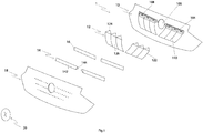
- FIG 1 a motor vehicle assembly, designated by the general reference 1, according to one embodiment of the invention.
- Set 1 shown on figure 1 is a set of motor vehicle.
- the motor vehicle assembly 1 comprises a support 10 intended to receive a first illuminating fabric 12 and a second illuminating fabric 14.
- the first illuminating fabric 12 comprises an illuminating part 122, called “first illuminating part” and a technical area 124 called “first technical area ”.
- the second illuminating fabric 14 comprises an illuminating part 142, called “second illuminating part” and a technical zone 144 called “second technical zone”.
- the technical zones 124 and 144 can be non-illuminating or else illuminating. In the case where the technical areas are illuminating, their brightness is, in any event, not satisfactory to ensure a satisfactory lighting function.
- the first and second illuminating fabrics 12, 14 are arranged so that the second illuminating part 142 covers the first technical zone 124.
- the face of the assembly 1 on which the illuminating fabrics 12, 14 are placed can appear. as illuminated over substantially its entire surface when the first and second illuminating fabrics 12, 14 are powered by a light source.
- the assembly 1 is an external assembly, configured to be visible from the outside of the vehicle, for example the assembly 1 is a part of an external part of the vehicle, or is attached to a part exterior of a vehicle.
- an illuminating fabric for the exterior of the vehicle, it will be noted that the illuminating fabric is very flexible compared to a conventional lighting device, so that it can easily conform to shapes. , in particular curves, of the exterior part very varied. Furthermore, an illuminating fabric is compact and can be easy to personalize by varying the colors of the light and / or the patterns arranged above the fabric. Thus, a particularly interesting application is to easily offer the user a personalized light signature of his vehicle.
- the support 10 intended to receive the illuminating fabrics 12, 14 comprises a substantially planar surface 102 for receiving the first illuminating part 122, and also comprises a cavity 104 for receiving the first technical zone 124 delimited by a wall set back relative to to the reception surface 102 of the first illuminating part 122.
- the first technical zone 124 can be housed inside the cavity 104, and is therefore set back from the reception surface 102.
- the illuminating part 122 of the first illuminating fabric 12 can be fixed to the flat part of the receiving support 102 by any suitable means, for example by gluing, or by a mechanical means making it possible to hang the illuminating fabric 12 on the support 10.
- the illuminating part 142 of the second illuminating fabric 14 (also called the second illuminating part) is attached to the cavity 104 so as to cover this cavity.
- the technical zone 124 of the first illuminating fabric 12 is thus covered by the illuminating part 142 of the second illuminating fabric 14.
- the second illuminating part 142 is furthermore preferably arranged substantially in the same plane as the first illuminating part 122.
- the face exterior of assembly 1 appears to be substantially planar.
- the support 10 may include a receiving cavity 106 of the second technical zone 144.
- the cavity is delimited by a wall set back from the receiving surface 102 of the first illuminating part 122.
- the second technical zone 144 can be housed inside the cavity 106, and therefore it is set back from the receiving surface 102. This also contributes to the exterior face of the assembly 1 appearing to be substantially planar.
- the cavities 104 and 106 are configured so as to accommodate the respective technical zones 124 and 144 while maintaining a sufficiently low curvature not to damage the illuminating fibers.
- the illuminating fabrics 12, 14 comprise optical fibers, which are not able to be bent over too small a radius without risk of damage.
- the first illuminating part 122 comprises a plurality of illuminating fabric panels 126 emitting light of different colors from each other, and the substantially planar receiving surface 102 of the first illuminating part 122 comprises protruding grooves 110 facing the edges of each panel 126 so as to ensure the luminous tightness of the edges of the various panels 126 of the first illuminating part 122.
- each of the receiving cavities 104 and 106 comprises in its recessed wall at least one through opening 108 intended to receive an element for connecting the illuminating fabric 12, 14 to a light source.
- the connection of the light fabrics 12, 14 to a light source is quick and easy.
- several openings 108 are made in the wall of the receiving cavity 104, 106. Most often, but this is not limiting, a light source is provided for each opening 108.
- the cavity 104 makes it possible to reserve a space for receiving the technical elements of the illuminating fabric, separated from the light source. As a result, it is possible to better protect the technical elements and the illuminating fabric, which are fragile and difficult to repair, while placing the light source outside the cavity 104, which is particularly advantageous in order to increase its service life. life. Indeed, in the case where the light source is an LED module, it is preferable that it is not confined in a closed housing because this impacts the cooling performance of the LED, and therefore its lifespan.
- the light source is placed in an area accessible, which facilitates its maintenance. The light source can also be deported to limit damage due to impact, and make it easier to change the damaged area.
- the second illuminating fabric 14 is received on a support 16.
- the support 16 is generally a panel or a plate of small thickness, and the other dimensions of which are substantially similar to those of the second illuminating part 142.
- the support 16 is arranged on the receiving cavity 104 of the first technical zone, and closes the cavity.
- the support panel 16 of the second illuminating part 142 covers the first technical zone 124.
- the panel 16 is opaque.
- the support panel 16 gives better mechanical resistance to the second illuminating fabric 14, and can also allow easier and faster mounting of the second illuminating fabric 14 on the support 10.
- the second illuminating fabric 14 is fixed to the support 16 by any means. suitable, such as gluing or mechanical fixing.
- the assembly 1 can comprise two second illuminating fabrics 14, each optionally received by a support 16.
- the two illuminating fabrics 14 can be separated by a decorative element 20.
- the technical zones 144 of each of the two second fabrics 14 are positioned between the two fabrics 14, and the decorative element 20 thus covers the technical zone 144 of each of the two second illuminating fabrics 14, which makes it possible to hide the technical zones 144 of the two second illuminating fabrics 14.
- each of the second technical zones 144 can be distinct or combined. In the event that they are merged, the same cavity 106 can advantageously accommodate the technical areas 144 of the two second illuminating fabrics 14.
- the assembly 1 comprises a plurality of n partially superimposed illuminating fabrics, n preferably being greater than 3.
- Each of the n illuminating fabrics comprises an illuminating part and a technical zone for joining the illuminating part to a. light source.
- the illuminating part of the illuminating fabric n is arranged on the support 10 so as to cover the technical zone of the illuminating fabric n-1.
- the assembly 1 further comprises an element 18 at least partially transparent or translucent, attached to the illuminating fabric (s) on their face opposite to the support 10.
- This element 18 is intended to cover the illuminating fabrics 12, 14 for them. protect. In some cases, only part of item 18 is transparent or translucent, so as to reveal a luminous pattern when the illuminating fabrics are supplied with light.
- the element 18 is located on the outside face of the external assembly when the latter is installed on the vehicle.
- the assembly 1 can be attached to a bumper skin of a vehicle. It can also be installed on other parts of the vehicle on which a uniform lighting function is desired, or on which it is desired to create a light pattern.
Landscapes
- Engineering & Computer Science (AREA)
- General Engineering & Computer Science (AREA)
- Physics & Mathematics (AREA)
- Microelectronics & Electronic Packaging (AREA)
- Optics & Photonics (AREA)
- Mechanical Engineering (AREA)
- Arrangements Of Lighting Devices For Vehicle Interiors, Mounting And Supporting Thereof, Circuits Therefore (AREA)
Claims (12)
- Kraftfahrzeug-Baugruppe (1) aufweisend- ein erstes Leuchtgewebe (12) mit einem ersten Leuchtabschnitt (122) und einem ersten technischen Bereich (124) zum Verbinden des ersten Leuchtabschnitts (122) an eine Lichtquelle, dadurch gekennzeichnet, dass die Baugruppe aufweist:- ein zweites Leuchtgewebe (14) mit einem zweiten Leuchtabschnitt (142) und einem zweiten technischen Bereich (144) zum Verbinden des zweiten Abschnitts (142) an eine Lichtquelle und- einen Träger (10) für das erste Leuchtgewebe (12) und das zweite Leuchtgewebe (14), wobei das zweite Leuchtabschnitt (142) auf dem Träger (10) so angeordnet ist, dass er den ersten technischen Bereich (124) abdeckt.
- Baugruppe (1) nach dem vorhergehenden Anspruch, welche derart konfiguriert ist, dass sie von außerhalb des Fahrzeugs sichtbar ist.
- Baugruppe (1) nach einem der vorhergehenden Ansprüche, wobei der Träger (10) aufweist:- eine im Wesentlichen flache Oberfläche (102) zur Aufnahme des ersten Leuchtabschnitts (122), und- einen Hohlraum (104) zur Aufnahme des ersten technischen Bereichs (124), welcher durch eine gegenüber der Aufnahmefläche (102) des ersten Leuchtabschnitts zurückgesetzte Wand begrenzt ist,
wobei der zweite Leuchtabschnitt (142) an dem Aufnahmehohlraum (104) des ersten technischen Bereichs (124) so angebracht ist, dass er den Aufnahmehohlraum des ersten technischen Bereichs abdeckt. - Baugruppe (1) nach Anspruch 3, wobei der Träger (10) einen Hohlraum (106) zur Aufnahme des zweiten technischen Bereichs (144) aufweist, der durch eine von der Aufnahmefläche (102) des ersten Leuchtabschnitts (122) zurückgesetzte Wand begrenzt ist.
- Baugruppe (1) nach einem der vorhergehenden Ansprüche, wobei:- der erste Leuchtabschnitt (122) mindestens zwei beleuchtende Stoffpaneele (126) aufweist, die jeweils so konfiguriert sind, dass sie Licht in verschiedenen Farben emittieren, und- der Träger (10) vorspringende Rippen (110) aufweist, die den Rändern jeder Platte (126) zugewandt sind, um die leuchtende Abdichtung der Ränder der Platten des ersten Leuchtabschnitts zu gewährleisten.
- Baugruppe (1) nach einem der Ansprüche 3 bis 5, wobei der Aufnahmehohlraum (104, 106) des ersten technischen Bereichs (124) oder des zweiten technischen Bereichs (144) derart eingerichtet ist, dass er den entsprechenden technischen Bereich unter Beachtung einer Krümmung des entsprechenden Leuchtgewebes aufnimmt, die ausreichend klein ist, um die Leuchtfasern nicht zu beschädigen.
- Baugruppe (1) nach einem der Ansprüche 3 bis 6, wobei die Wand Ausnehmung (104, 106) des ersten technischen Bereichs (124) oder des zweiten technischen Bereichs (144) mindestens eine Durchgangsöffnung (108) aufweist, die dazu bestimmt ist, ein Element zum Verbinden des Lichtgewebes mit einer Lichtquelle aufzunehmen.
- Baugruppe (1) nach einem der vorhergehenden Ansprüche, mit einer Trägerplatte (16) des zweiten Leuchtabschnitts (142), die den ersten technischen Bereich (124) abdeckt, wobei die Trägerplatte (16) vorzugsweise lichtundurchlässig ist.
- Baugruppe (1) nach einem der vorhergehenden Ansprüche, umfassend zwei zweite Leuchtgewebe (14), die durch ein dekoratives Element (20) getrennt sind, wobei das dekorative Element (20) den zweiten technischen Bereich (144) jedes der beiden zweiten Leuchtgewebe (14) abdeckt.
- Baugruppe (1) nach einem der vorhergehenden Ansprüche mit einer Vielzahl von n teilweise übereinanderliegenden Leuchtgeweben (12, 14), die jeweils einen Leuchtabschnitt und eine technische Zone zum Verbinden des Leuchtabschnitts mit einer Lichtquelle aufweisen, wobei der Leuchtabschnitt des Leuchtgewebes n auf dem Träger (10) derart angeordnet ist, dass er die technische Zone des Leuchtgewebes n-1 abdeckt.
- Baugruppe (1) nach einem der vorhergehenden Ansprüche, die ferner ein zumindest teilweise transparentes (18) oder lichtdurchlässiges Element umfasst, das dazu bestimmt ist, die Leuchtgewebe (12, 14) zu bedecken, um sie zu schützen und möglicherweise ein Leuchtmuster zu zeigen.
- Baugruppe (1) nach einem der vorhergehenden Ansprüche, konfiguriert zur Befestigung an einer Stoßfängerhaut (2).
Applications Claiming Priority (1)
| Application Number | Priority Date | Filing Date | Title |
|---|---|---|---|
| FR1859502A FR3087168A1 (fr) | 2018-10-12 | 2018-10-12 | Ensemble de vehicule automobile comprenant un tissu eclairant |
Publications (2)
| Publication Number | Publication Date |
|---|---|
| EP3636492A1 EP3636492A1 (de) | 2020-04-15 |
| EP3636492B1 true EP3636492B1 (de) | 2021-05-12 |
Family
ID=65244276
Family Applications (1)
| Application Number | Title | Priority Date | Filing Date |
|---|---|---|---|
| EP19201699.6A Active EP3636492B1 (de) | 2018-10-12 | 2019-10-07 | Kraftfahrzeugeinheit, die ein leuchtgewebe umfasst |
Country Status (3)
| Country | Link |
|---|---|
| EP (1) | EP3636492B1 (de) |
| CN (1) | CN111043567A (de) |
| FR (1) | FR3087168A1 (de) |
Citations (1)
| Publication number | Priority date | Publication date | Assignee | Title |
|---|---|---|---|---|
| WO2008035010A1 (fr) * | 2006-09-19 | 2008-03-27 | Prismaflex International | Nappe textile éclairante, procédé de transformation et dispositif lumineux comprenant une pluralité de zones éclairantes |
Family Cites Families (7)
| Publication number | Priority date | Publication date | Assignee | Title |
|---|---|---|---|---|
| DE19803537A1 (de) * | 1998-01-30 | 1999-08-05 | Hella Kg Hueck & Co | Leuchte für Fahrzeuge |
| DE19838224C2 (de) * | 1998-08-22 | 2000-11-09 | Daimler Chrysler Ag | Frontleuchtenanordnung für Kraftfahrzeuge |
| US20090161378A1 (en) * | 2007-12-20 | 2009-06-25 | Andreas Enz | Slim profile light assembly for an exterior vehicle mirror |
| DE102013227195A1 (de) * | 2013-12-27 | 2015-07-02 | Automotive Lighting Reutlingen Gmbh | Kraftfahrzeugleuchte mit einem linien- oder flächenhaften Erscheinungsbild |
| FR3046389B1 (fr) | 2015-12-30 | 2019-05-31 | Compagnie Plastic Omnium | Piece exterieure de vehicule automobile comportant un tissu eclairant |
| FR3047295B1 (fr) * | 2016-01-29 | 2020-03-06 | Valeo Vision | Dispositif lumineux segmente pour un vehicule automobile utilisant plusieurs guides de lumiere |
| US10240745B2 (en) * | 2016-11-22 | 2019-03-26 | Valeo North America, Inc. | Fiber optic light panel device with plural outputs |
-
2018
- 2018-10-12 FR FR1859502A patent/FR3087168A1/fr not_active Ceased
-
2019
- 2019-10-07 EP EP19201699.6A patent/EP3636492B1/de active Active
- 2019-10-10 CN CN201910956623.9A patent/CN111043567A/zh active Pending
Patent Citations (1)
| Publication number | Priority date | Publication date | Assignee | Title |
|---|---|---|---|---|
| WO2008035010A1 (fr) * | 2006-09-19 | 2008-03-27 | Prismaflex International | Nappe textile éclairante, procédé de transformation et dispositif lumineux comprenant une pluralité de zones éclairantes |
Also Published As
| Publication number | Publication date |
|---|---|
| FR3087168A1 (fr) | 2020-04-17 |
| EP3636492A1 (de) | 2020-04-15 |
| CN111043567A (zh) | 2020-04-21 |
Similar Documents
| Publication | Publication Date | Title |
|---|---|---|
| EP4065882B1 (de) | Lichtmodul eines kraftfahrzeugs, das mit einem optischen element ausgestattet ist | |
| EP3313680B1 (de) | Kraftfahrzeugheckklappe mit einer kunststoffkastenstruktur | |
| EP3397520B1 (de) | Kraftfahrzeugaussenteil mit einem leuchtenden gewebe | |
| FR2817820A1 (fr) | Piece de carrosserie de vehicule automobile munie d'un dispositif optique | |
| FR3046655A1 (fr) | Bloc optique d’eclairage ou de signalisation pour vehicule automobile comportant un masque opalin | |
| FR2937929A1 (fr) | Panneau de garnissage de vehicule automobile comprenant une zone formant pictogramme illuminee par une couche emettrice de lumiere | |
| EP3884206B1 (de) | Multifunktionales lichtmodul mit zwei flachen lichtleitern | |
| FR3056283A1 (fr) | Dispositif lumineux comportant une source lumineuse surfacique | |
| FR3106651A1 (fr) | Guide de lumière plat pour module lumineux de signalisation de véhicule automobile | |
| WO2020020601A1 (fr) | Portière de véhicule automobile comportant une source lumineuse portée par un joint intérieur | |
| FR2557046A1 (fr) | Panneau pour vehicules a moteur | |
| EP3980683B1 (de) | Signalleuchte mit zwei freitragenden lichtleitern | |
| EP3636492B1 (de) | Kraftfahrzeugeinheit, die ein leuchtgewebe umfasst | |
| EP1378393B1 (de) | Signaleinrichtung und Karosserieteil für Kraftfahrzeug mit einer solchen | |
| EP3270052A1 (de) | Halterung eines leuchtmittels für kraftfahrzeug | |
| EP3899361B1 (de) | Lichtelement für karosseriebauteil aus spritzgegossenem polycarbonat | |
| FR3087169A1 (fr) | Ensemble pour vehicule automobile comprenant un tissu eclairant | |
| EP3580095A1 (de) | Kraftfahrzeugtürverkleidung mit einer umgebungsbeleuchtungsvorrichtung | |
| FR3088869A1 (fr) | Dispositif de pré-positionnement et de maintien d’un élément sur un boitier | |
| FR3121501A1 (fr) | Ensemble guide de lumière pour un véhicule automobile | |
| EP3996121B1 (de) | Steuerungs- und/oder signalhilfsmittel, das an seinem montageumfang zugänglich ist und verfahren zur montage auf einem rohrförmigen träger | |
| EP3803199B1 (de) | Optische einheit für kraftfahrzeug und kraftfahrzeug mit einem solchen element | |
| EP4722040A1 (de) | Verkleidungselement mit einem hinterleuchteten logo und einem radar | |
| EP4729362A1 (de) | Fahrzeugaussenverkleidungsteil mit einem auf einen hauptkörper geklebten verkleidungselement | |
| FR3153397A1 (fr) | Dispositif lumineux pour véhicule |
Legal Events
| Date | Code | Title | Description |
|---|---|---|---|
| PUAI | Public reference made under article 153(3) epc to a published international application that has entered the european phase |
Free format text: ORIGINAL CODE: 0009012 |
|
| STAA | Information on the status of an ep patent application or granted ep patent |
Free format text: STATUS: THE APPLICATION HAS BEEN PUBLISHED |
|
| AK | Designated contracting states |
Kind code of ref document: A1 Designated state(s): AL AT BE BG CH CY CZ DE DK EE ES FI FR GB GR HR HU IE IS IT LI LT LU LV MC MK MT NL NO PL PT RO RS SE SI SK SM TR |
|
| AX | Request for extension of the european patent |
Extension state: BA ME |
|
| STAA | Information on the status of an ep patent application or granted ep patent |
Free format text: STATUS: REQUEST FOR EXAMINATION WAS MADE |
|
| 17P | Request for examination filed |
Effective date: 20201015 |
|
| RBV | Designated contracting states (corrected) |
Designated state(s): AL AT BE BG CH CY CZ DE DK EE ES FI FR GB GR HR HU IE IS IT LI LT LU LV MC MK MT NL NO PL PT RO RS SE SI SK SM TR |
|
| GRAP | Despatch of communication of intention to grant a patent |
Free format text: ORIGINAL CODE: EPIDOSNIGR1 |
|
| STAA | Information on the status of an ep patent application or granted ep patent |
Free format text: STATUS: GRANT OF PATENT IS INTENDED |
|
| INTG | Intention to grant announced |
Effective date: 20201210 |
|
| GRAS | Grant fee paid |
Free format text: ORIGINAL CODE: EPIDOSNIGR3 |
|
| GRAA | (expected) grant |
Free format text: ORIGINAL CODE: 0009210 |
|
| STAA | Information on the status of an ep patent application or granted ep patent |
Free format text: STATUS: THE PATENT HAS BEEN GRANTED |
|
| AK | Designated contracting states |
Kind code of ref document: B1 Designated state(s): AL AT BE BG CH CY CZ DE DK EE ES FI FR GB GR HR HU IE IS IT LI LT LU LV MC MK MT NL NO PL PT RO RS SE SI SK SM TR |
|
| REG | Reference to a national code |
Ref country code: GB Ref legal event code: FG4D Free format text: NOT ENGLISH |
|
| REG | Reference to a national code |
Ref country code: CH Ref legal event code: EP |
|
| REG | Reference to a national code |
Ref country code: DE Ref legal event code: R096 Ref document number: 602019004582 Country of ref document: DE |
|
| REG | Reference to a national code |
Ref country code: IE Ref legal event code: FG4D Free format text: LANGUAGE OF EP DOCUMENT: FRENCH |
|
| REG | Reference to a national code |
Ref country code: AT Ref legal event code: REF Ref document number: 1391986 Country of ref document: AT Kind code of ref document: T Effective date: 20210615 |
|
| REG | Reference to a national code |
Ref country code: LT Ref legal event code: MG9D |
|
| REG | Reference to a national code |
Ref country code: AT Ref legal event code: MK05 Ref document number: 1391986 Country of ref document: AT Kind code of ref document: T Effective date: 20210512 |
|
| REG | Reference to a national code |
Ref country code: NL Ref legal event code: MP Effective date: 20210512 |
|
| PG25 | Lapsed in a contracting state [announced via postgrant information from national office to epo] |
Ref country code: BG Free format text: LAPSE BECAUSE OF FAILURE TO SUBMIT A TRANSLATION OF THE DESCRIPTION OR TO PAY THE FEE WITHIN THE PRESCRIBED TIME-LIMIT Effective date: 20210812 Ref country code: AT Free format text: LAPSE BECAUSE OF FAILURE TO SUBMIT A TRANSLATION OF THE DESCRIPTION OR TO PAY THE FEE WITHIN THE PRESCRIBED TIME-LIMIT Effective date: 20210512 Ref country code: LT Free format text: LAPSE BECAUSE OF FAILURE TO SUBMIT A TRANSLATION OF THE DESCRIPTION OR TO PAY THE FEE WITHIN THE PRESCRIBED TIME-LIMIT Effective date: 20210512 Ref country code: HR Free format text: LAPSE BECAUSE OF FAILURE TO SUBMIT A TRANSLATION OF THE DESCRIPTION OR TO PAY THE FEE WITHIN THE PRESCRIBED TIME-LIMIT Effective date: 20210512 Ref country code: FI Free format text: LAPSE BECAUSE OF FAILURE TO SUBMIT A TRANSLATION OF THE DESCRIPTION OR TO PAY THE FEE WITHIN THE PRESCRIBED TIME-LIMIT Effective date: 20210512 |
|
| PG25 | Lapsed in a contracting state [announced via postgrant information from national office to epo] |
Ref country code: NO Free format text: LAPSE BECAUSE OF FAILURE TO SUBMIT A TRANSLATION OF THE DESCRIPTION OR TO PAY THE FEE WITHIN THE PRESCRIBED TIME-LIMIT Effective date: 20210812 Ref country code: LV Free format text: LAPSE BECAUSE OF FAILURE TO SUBMIT A TRANSLATION OF THE DESCRIPTION OR TO PAY THE FEE WITHIN THE PRESCRIBED TIME-LIMIT Effective date: 20210512 Ref country code: PL Free format text: LAPSE BECAUSE OF FAILURE TO SUBMIT A TRANSLATION OF THE DESCRIPTION OR TO PAY THE FEE WITHIN THE PRESCRIBED TIME-LIMIT Effective date: 20210512 Ref country code: RS Free format text: LAPSE BECAUSE OF FAILURE TO SUBMIT A TRANSLATION OF THE DESCRIPTION OR TO PAY THE FEE WITHIN THE PRESCRIBED TIME-LIMIT Effective date: 20210512 Ref country code: PT Free format text: LAPSE BECAUSE OF FAILURE TO SUBMIT A TRANSLATION OF THE DESCRIPTION OR TO PAY THE FEE WITHIN THE PRESCRIBED TIME-LIMIT Effective date: 20210913 Ref country code: SE Free format text: LAPSE BECAUSE OF FAILURE TO SUBMIT A TRANSLATION OF THE DESCRIPTION OR TO PAY THE FEE WITHIN THE PRESCRIBED TIME-LIMIT Effective date: 20210512 Ref country code: IS Free format text: LAPSE BECAUSE OF FAILURE TO SUBMIT A TRANSLATION OF THE DESCRIPTION OR TO PAY THE FEE WITHIN THE PRESCRIBED TIME-LIMIT Effective date: 20210912 Ref country code: GR Free format text: LAPSE BECAUSE OF FAILURE TO SUBMIT A TRANSLATION OF THE DESCRIPTION OR TO PAY THE FEE WITHIN THE PRESCRIBED TIME-LIMIT Effective date: 20210813 |
|
| PG25 | Lapsed in a contracting state [announced via postgrant information from national office to epo] |
Ref country code: NL Free format text: LAPSE BECAUSE OF FAILURE TO SUBMIT A TRANSLATION OF THE DESCRIPTION OR TO PAY THE FEE WITHIN THE PRESCRIBED TIME-LIMIT Effective date: 20210512 |
|
| PG25 | Lapsed in a contracting state [announced via postgrant information from national office to epo] |
Ref country code: SK Free format text: LAPSE BECAUSE OF FAILURE TO SUBMIT A TRANSLATION OF THE DESCRIPTION OR TO PAY THE FEE WITHIN THE PRESCRIBED TIME-LIMIT Effective date: 20210512 Ref country code: EE Free format text: LAPSE BECAUSE OF FAILURE TO SUBMIT A TRANSLATION OF THE DESCRIPTION OR TO PAY THE FEE WITHIN THE PRESCRIBED TIME-LIMIT Effective date: 20210512 Ref country code: ES Free format text: LAPSE BECAUSE OF FAILURE TO SUBMIT A TRANSLATION OF THE DESCRIPTION OR TO PAY THE FEE WITHIN THE PRESCRIBED TIME-LIMIT Effective date: 20210512 Ref country code: DK Free format text: LAPSE BECAUSE OF FAILURE TO SUBMIT A TRANSLATION OF THE DESCRIPTION OR TO PAY THE FEE WITHIN THE PRESCRIBED TIME-LIMIT Effective date: 20210512 Ref country code: CZ Free format text: LAPSE BECAUSE OF FAILURE TO SUBMIT A TRANSLATION OF THE DESCRIPTION OR TO PAY THE FEE WITHIN THE PRESCRIBED TIME-LIMIT Effective date: 20210512 Ref country code: RO Free format text: LAPSE BECAUSE OF FAILURE TO SUBMIT A TRANSLATION OF THE DESCRIPTION OR TO PAY THE FEE WITHIN THE PRESCRIBED TIME-LIMIT Effective date: 20210512 Ref country code: SM Free format text: LAPSE BECAUSE OF FAILURE TO SUBMIT A TRANSLATION OF THE DESCRIPTION OR TO PAY THE FEE WITHIN THE PRESCRIBED TIME-LIMIT Effective date: 20210512 |
|
| REG | Reference to a national code |
Ref country code: DE Ref legal event code: R097 Ref document number: 602019004582 Country of ref document: DE |
|
| PLBE | No opposition filed within time limit |
Free format text: ORIGINAL CODE: 0009261 |
|
| STAA | Information on the status of an ep patent application or granted ep patent |
Free format text: STATUS: NO OPPOSITION FILED WITHIN TIME LIMIT |
|
| 26N | No opposition filed |
Effective date: 20220215 |
|
| PG25 | Lapsed in a contracting state [announced via postgrant information from national office to epo] |
Ref country code: IS Free format text: LAPSE BECAUSE OF FAILURE TO SUBMIT A TRANSLATION OF THE DESCRIPTION OR TO PAY THE FEE WITHIN THE PRESCRIBED TIME-LIMIT Effective date: 20210912 Ref country code: AL Free format text: LAPSE BECAUSE OF FAILURE TO SUBMIT A TRANSLATION OF THE DESCRIPTION OR TO PAY THE FEE WITHIN THE PRESCRIBED TIME-LIMIT Effective date: 20210512 |
|
| REG | Reference to a national code |
Ref country code: BE Ref legal event code: MM Effective date: 20211031 |
|
| PG25 | Lapsed in a contracting state [announced via postgrant information from national office to epo] |
Ref country code: MC Free format text: LAPSE BECAUSE OF FAILURE TO SUBMIT A TRANSLATION OF THE DESCRIPTION OR TO PAY THE FEE WITHIN THE PRESCRIBED TIME-LIMIT Effective date: 20210512 |
|
| PG25 | Lapsed in a contracting state [announced via postgrant information from national office to epo] |
Ref country code: LU Free format text: LAPSE BECAUSE OF NON-PAYMENT OF DUE FEES Effective date: 20211007 Ref country code: IT Free format text: LAPSE BECAUSE OF FAILURE TO SUBMIT A TRANSLATION OF THE DESCRIPTION OR TO PAY THE FEE WITHIN THE PRESCRIBED TIME-LIMIT Effective date: 20210512 Ref country code: BE Free format text: LAPSE BECAUSE OF NON-PAYMENT OF DUE FEES Effective date: 20211031 |
|
| PG25 | Lapsed in a contracting state [announced via postgrant information from national office to epo] |
Ref country code: IE Free format text: LAPSE BECAUSE OF NON-PAYMENT OF DUE FEES Effective date: 20211007 |
|
| REG | Reference to a national code |
Ref country code: CH Ref legal event code: PL |
|
| P01 | Opt-out of the competence of the unified patent court (upc) registered |
Effective date: 20230517 |
|
| PG25 | Lapsed in a contracting state [announced via postgrant information from national office to epo] |
Ref country code: CY Free format text: LAPSE BECAUSE OF FAILURE TO SUBMIT A TRANSLATION OF THE DESCRIPTION OR TO PAY THE FEE WITHIN THE PRESCRIBED TIME-LIMIT Effective date: 20210512 |
|
| PG25 | Lapsed in a contracting state [announced via postgrant information from national office to epo] |
Ref country code: LI Free format text: LAPSE BECAUSE OF NON-PAYMENT OF DUE FEES Effective date: 20221031 Ref country code: HU Free format text: LAPSE BECAUSE OF FAILURE TO SUBMIT A TRANSLATION OF THE DESCRIPTION OR TO PAY THE FEE WITHIN THE PRESCRIBED TIME-LIMIT; INVALID AB INITIO Effective date: 20191007 Ref country code: CH Free format text: LAPSE BECAUSE OF NON-PAYMENT OF DUE FEES Effective date: 20221031 |
|
| PG25 | Lapsed in a contracting state [announced via postgrant information from national office to epo] |
Ref country code: MK Free format text: LAPSE BECAUSE OF FAILURE TO SUBMIT A TRANSLATION OF THE DESCRIPTION OR TO PAY THE FEE WITHIN THE PRESCRIBED TIME-LIMIT Effective date: 20210512 |
|
| GBPC | Gb: european patent ceased through non-payment of renewal fee |
Effective date: 20231007 |
|
| PG25 | Lapsed in a contracting state [announced via postgrant information from national office to epo] |
Ref country code: TR Free format text: LAPSE BECAUSE OF FAILURE TO SUBMIT A TRANSLATION OF THE DESCRIPTION OR TO PAY THE FEE WITHIN THE PRESCRIBED TIME-LIMIT Effective date: 20210512 |
|
| PG25 | Lapsed in a contracting state [announced via postgrant information from national office to epo] |
Ref country code: GB Free format text: LAPSE BECAUSE OF NON-PAYMENT OF DUE FEES Effective date: 20231007 |
|
| PG25 | Lapsed in a contracting state [announced via postgrant information from national office to epo] |
Ref country code: GB Free format text: LAPSE BECAUSE OF NON-PAYMENT OF DUE FEES Effective date: 20231007 |
|
| REG | Reference to a national code |
Ref country code: DE Ref legal event code: R081 Ref document number: 602019004582 Country of ref document: DE Owner name: OPMOBILITY SE, FR Free format text: FORMER OWNER: COMPAGNIE PLASTIC OMNIUM SE, LYON, FR Ref country code: DE Ref legal event code: R081 Ref document number: 602019004582 Country of ref document: DE Owner name: OPMOBILITY SE, FR Free format text: FORMER OWNER: COMPAGNIE PLASTIC OMNIUM, LYON, FR |
|
| PG25 | Lapsed in a contracting state [announced via postgrant information from national office to epo] |
Ref country code: MT Free format text: LAPSE BECAUSE OF FAILURE TO SUBMIT A TRANSLATION OF THE DESCRIPTION OR TO PAY THE FEE WITHIN THE PRESCRIBED TIME-LIMIT Effective date: 20210512 |
|
| PGFP | Annual fee paid to national office [announced via postgrant information from national office to epo] |
Ref country code: DE Payment date: 20251021 Year of fee payment: 7 |
|
| PGFP | Annual fee paid to national office [announced via postgrant information from national office to epo] |
Ref country code: FR Payment date: 20251030 Year of fee payment: 7 |