EP3636496A1 - Anordnung angewendet für kraftfahrzeugstossstange - Google Patents
Anordnung angewendet für kraftfahrzeugstossstange Download PDFInfo
- Publication number
- EP3636496A1 EP3636496A1 EP19189491.4A EP19189491A EP3636496A1 EP 3636496 A1 EP3636496 A1 EP 3636496A1 EP 19189491 A EP19189491 A EP 19189491A EP 3636496 A1 EP3636496 A1 EP 3636496A1
- Authority
- EP
- European Patent Office
- Prior art keywords
- deformers
- configuration
- deformation element
- bumpers
- bumper
- Prior art date
- Legal status (The legal status is an assumption and is not a legal conclusion. Google has not performed a legal analysis and makes no representation as to the accuracy of the status listed.)
- Ceased
Links
- 229910000831 Steel Inorganic materials 0.000 claims description 5
- 239000010959 steel Substances 0.000 claims description 5
- XAGFODPZIPBFFR-UHFFFAOYSA-N aluminium Chemical compound [Al] XAGFODPZIPBFFR-UHFFFAOYSA-N 0.000 claims description 3
- 229910052782 aluminium Inorganic materials 0.000 claims description 3
- 230000007935 neutral effect Effects 0.000 claims description 3
- 239000000463 material Substances 0.000 claims description 2
- 238000010521 absorption reaction Methods 0.000 abstract description 5
- 238000003466 welding Methods 0.000 abstract 1
- 230000000712 assembly Effects 0.000 description 2
- 238000000429 assembly Methods 0.000 description 2
- 238000005304 joining Methods 0.000 description 2
- 238000004519 manufacturing process Methods 0.000 description 2
- 230000007704 transition Effects 0.000 description 2
- 230000008901 benefit Effects 0.000 description 1
- 230000008859 change Effects 0.000 description 1
- 230000001447 compensatory effect Effects 0.000 description 1
- 230000006835 compression Effects 0.000 description 1
- 238000007906 compression Methods 0.000 description 1
- 230000008878 coupling Effects 0.000 description 1
- 238000010168 coupling process Methods 0.000 description 1
- 238000005859 coupling reaction Methods 0.000 description 1
- 238000009826 distribution Methods 0.000 description 1
- 239000000945 filler Substances 0.000 description 1
- 239000006260 foam Substances 0.000 description 1
- 239000002828 fuel tank Substances 0.000 description 1
- 239000007789 gas Substances 0.000 description 1
- 238000000034 method Methods 0.000 description 1
- 230000000750 progressive effect Effects 0.000 description 1
- 230000009467 reduction Effects 0.000 description 1
Images



Classifications
-
- B—PERFORMING OPERATIONS; TRANSPORTING
- B60—VEHICLES IN GENERAL
- B60R—VEHICLES, VEHICLE FITTINGS, OR VEHICLE PARTS, NOT OTHERWISE PROVIDED FOR
- B60R19/00—Wheel guards; Radiator guards, e.g. grilles; Obstruction removers; Fittings damping bouncing force in collisions
- B60R19/02—Bumpers, i.e. impact receiving or absorbing members for protecting vehicles or fending off blows from other vehicles or objects
- B60R19/24—Arrangements for mounting bumpers on vehicles
- B60R19/26—Arrangements for mounting bumpers on vehicles comprising yieldable mounting means
- B60R19/34—Arrangements for mounting bumpers on vehicles comprising yieldable mounting means destroyed upon impact, e.g. one-shot type
-
- B—PERFORMING OPERATIONS; TRANSPORTING
- B60—VEHICLES IN GENERAL
- B60R—VEHICLES, VEHICLE FITTINGS, OR VEHICLE PARTS, NOT OTHERWISE PROVIDED FOR
- B60R19/00—Wheel guards; Radiator guards, e.g. grilles; Obstruction removers; Fittings damping bouncing force in collisions
- B60R19/02—Bumpers, i.e. impact receiving or absorbing members for protecting vehicles or fending off blows from other vehicles or objects
- B60R19/03—Bumpers, i.e. impact receiving or absorbing members for protecting vehicles or fending off blows from other vehicles or objects characterised by material, e.g. composite
Definitions
- the present invention refers to the layout applied to bumpers of automotive vehicles in the form of a set of deformations introduced to the bumpers, resulting in a new profile with eight sides, manufactured in high resistance steels or aluminum, not restricted only to these materials, with progressively spaced and alternating pre-deformers. This allows the two (right and left) parts of the bumper assembly to be produced by the same tooling, reducing serial production costs, without compromising the robustness in deformation energy control and subsequent high efficiency of the impact absorption.
- a typical bumper's performance is based on its ability to protect the vehicle.
- a typical deformation element design generally consists of two embossed halves, with a square or rectangular profile or section, overlapping, welded and fixed to the axial axis of the vehicle and, therefore, longitudinally to its usual direction of movement, being positioned at the front and at the rear of the vehicle.
- both the rear bumper and the front bumper in the conventional deformation assembly consist of a plastic part specific to each vehicle, a filler (foam), the beam (steel or equivalent), the deformation assembly (steel or aluminum) and the fixing plate (steel or equivalent), which are mounted on the rear or front and fixed to the vehicle's cantrails by any chosen method.
- the bumper deformation element With the bumper deformation element mounted on the vehicle, its main task is to dissipate the energy that is absorbed in a controlled way during a collision between the vehicle and another object.
- the bumper deformation element must primarily absorb the kinetic energy resulting from collisions by plastic deformation, prevent intrusion into the passenger compartment and protect the fuel tank by minimizing forces acting on the vehicle during a collision, directly in the front or in the rear or as well obliquely from front or rear.
- the increase in performance is achieved when the greater available volume of the deformation element is contributing to the absorption of impact energy in order to obtain a better distribution of the impact force on the vehicle cantrails.
- the association of multi-sided polygonal forms (hexagons, octagons, decagons, among others) with progressively spaced and alternating pre-deformers in the deformation assemblies has enabled a greater capacity of energy absorption and reduction of the component mass, therefore, improvements to the bumper deformation assemblies design are desirable.
- This invention innovates the arrangement, presenting a layout applied to the impact bumper for motor vehicles which completely or in part satisfies the standards defined by the assemblers for the manufacture of bumpers in order to absorb the largest quantity of impact energy at the shortest possible distance, absorbing as much energy as possible with less mass, since minimizing the bumper impact mass has nowadays become mandatory due to restrictions on emission of gases.
- the pre-deformers make a smooth transition from the front portion to the rear portion of the deformation elements, adjusting in contact with the beam, compensating the longitudinal curvature existing in the front of modern vehicles.
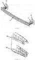
- the present invention relates to the layout applied to bumpers of automotive vehicles in the form of a deformation assembly (1b, 1c) which is constituted by a configuration with regular medium eight sides, which is kept along the entire length, with alternating pre-deformers.
- a deformation assembly (1b, 1c) which is constituted by a configuration with regular medium eight sides, which is kept along the entire length, with alternating pre-deformers.
- they are responsible for joining the beam (1a) with the two bulkhead plates (1d, 1e), which are attached to the vehicle cantrails.
- the deformation elements are formed by two laterally welded (3) overlapping semi-bodies (2a, 2b), a fact made possible by the shape and coupling characteristics, and this form of union is not restricted.
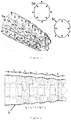
- the cross-sectional view shows the medium regular octagonal profile (4d, 4b, 4c) which is kept along the entire length, with pre-deformers, that is, preformed structures to direct and control behavior during collapse of the deformation elements.
- the normal direction of the pre-deformers completely alternates from the front portion to the rear portion of the deformation elements (5a, 5b, 5c).
- each pre-deformer the distance that follows from crest to crest following the shape, is the same, meaning that the deeper pre-deformers are shorter and vice versa. This is ensured by the cosine form, which ensures a progressive change in the aspect ratio by employing constant curves of the same length for each of the pre-deformers, thus, optimizing energy absorption.
- the pre-deformers are arranged progressively along the length of the deformation elements, being proportionally arranged along the compression axis (7), adjusting symmetrically both in contact with the bumper beam and with the bulkhead plate which is attached to the vehicle's cantrail.
- the deformation element exhibits symmetrical growth of the width along the longitudinal axis (8), that is, it has smaller dimensions of width and height in the front portion (contact with the beam) than in the rear portion (contact with the bulkhead plate), not being restricted to this positive configuration, which may also be neutral (constant length and width dimensions along the length) or negative (inverse of the positive configuration described above), in order to adapt to and take advantage of the available space in contact with both the beam and the bulkhead plate.
Landscapes
- Engineering & Computer Science (AREA)
- Mechanical Engineering (AREA)
- Body Structure For Vehicles (AREA)
Applications Claiming Priority (1)
| Application Number | Priority Date | Filing Date | Title |
|---|---|---|---|
| BR202018070682U BR202018070682U2 (pt) | 2018-10-08 | 2018-10-08 | disposição aplicada em para-choque de veículos automotores |
Publications (1)
| Publication Number | Publication Date |
|---|---|
| EP3636496A1 true EP3636496A1 (de) | 2020-04-15 |
Family
ID=67514450
Family Applications (1)
| Application Number | Title | Priority Date | Filing Date |
|---|---|---|---|
| EP19189491.4A Ceased EP3636496A1 (de) | 2018-10-08 | 2019-07-31 | Anordnung angewendet für kraftfahrzeugstossstange |
Country Status (3)
| Country | Link |
|---|---|
| US (1) | US20200108788A1 (de) |
| EP (1) | EP3636496A1 (de) |
| BR (1) | BR202018070682U2 (de) |
Families Citing this family (5)
| Publication number | Priority date | Publication date | Assignee | Title |
|---|---|---|---|---|
| DE102018129724B4 (de) * | 2018-11-26 | 2022-08-04 | Benteler Automobiltechnik Gmbh | Fahrzeugbauteil für ein Fahrzeug |
| CN113811459B (zh) * | 2019-10-10 | 2023-10-27 | 河西工业株式会社 | 车辆用缓冲部件 |
| ES3028333T3 (en) * | 2020-01-28 | 2025-06-18 | Outokumpu Oy | Expanded tube for a motor vehicle crash box and manufacturing method for it |
| DE102020112125B3 (de) * | 2020-05-05 | 2021-10-21 | Kirchhoff Automotive Deutschland Gmbh | Baugruppe für ein Fahrzeug |
| CN116214031B (zh) * | 2022-12-29 | 2024-01-16 | 广西天恒汽车部件制造股份有限公司 | 一种刀片式动力电池托盘横梁焊接方法 |
Citations (1)
| Publication number | Priority date | Publication date | Assignee | Title |
|---|---|---|---|---|
| US20140346790A1 (en) * | 2012-01-18 | 2014-11-27 | Magna International Inc. | Sinusoidal Crush Can Assembly |
-
2018
- 2018-10-08 BR BR202018070682U patent/BR202018070682U2/pt not_active IP Right Cessation
-
2019
- 2019-07-31 US US16/528,003 patent/US20200108788A1/en not_active Abandoned
- 2019-07-31 EP EP19189491.4A patent/EP3636496A1/de not_active Ceased
Patent Citations (1)
| Publication number | Priority date | Publication date | Assignee | Title |
|---|---|---|---|---|
| US20140346790A1 (en) * | 2012-01-18 | 2014-11-27 | Magna International Inc. | Sinusoidal Crush Can Assembly |
Also Published As
| Publication number | Publication date |
|---|---|
| BR202018070682U2 (pt) | 2020-04-28 |
| US20200108788A1 (en) | 2020-04-09 |
Similar Documents
| Publication | Publication Date | Title |
|---|---|---|
| EP3636496A1 (de) | Anordnung angewendet für kraftfahrzeugstossstange | |
| US9266484B2 (en) | Crush box | |
| US10696255B2 (en) | Impact absorbing element | |
| EP4041619B1 (de) | Fahrzeugseitenstruktur | |
| US7252314B2 (en) | Crash energy absorption member | |
| EP2821325A1 (de) | Stoßdämpfungsvorrichtung eines Fahrzeugs und Stoßdämpfungsstruktur eines Fahrzeugs | |
| JP7734699B2 (ja) | 車両構造体 | |
| EP2301809A1 (de) | Aufprallabsorbierendes glied | |
| US20120119526A1 (en) | Deformation element for a motor vehicle | |
| EP2786903B1 (de) | Stossdämpfendes element für ein fahrzeug | |
| KR20190067868A (ko) | 범퍼 빔의 여러 벽에 리브들을 가지는 범퍼 빔 | |
| US20240075987A1 (en) | Vehicle front rail | |
| KR20190067869A (ko) | 8 형상의 단면을 갖는 범퍼 빔 | |
| JP2015086987A (ja) | 衝撃吸収部材 | |
| JP2009154617A (ja) | 車両用アンダメンバ構造 | |
| JP5997085B2 (ja) | 車両衝撃吸収部材 | |
| WO2014126183A1 (ja) | エネルギー吸収部材 | |
| JP2009096225A (ja) | エネルギー吸収部材 | |
| CN209776362U (zh) | 汽车吸能盒及汽车 | |
| JP5237252B2 (ja) | 自動車のバンパー構造体 | |
| WO2012153792A1 (ja) | エネルギー吸収部材 | |
| CN112672926A (zh) | 能量吸收装置、机动车辆车身及能量吸收装置的制造方法 | |
| CN121492837A (zh) | 冲击吸收元件和组装方法 | |
| CN223237556U (zh) | 防撞梁总成和具有其的车辆 | |
| KR101137257B1 (ko) | 차량용 범퍼빔 유닛 |
Legal Events
| Date | Code | Title | Description |
|---|---|---|---|
| STAA | Information on the status of an ep patent application or granted ep patent |
Free format text: STATUS: UNKNOWN |
|
| PUAI | Public reference made under article 153(3) epc to a published international application that has entered the european phase |
Free format text: ORIGINAL CODE: 0009012 |
|
| STAA | Information on the status of an ep patent application or granted ep patent |
Free format text: STATUS: THE APPLICATION HAS BEEN PUBLISHED |
|
| AK | Designated contracting states |
Kind code of ref document: A1 Designated state(s): AL AT BE BG CH CY CZ DE DK EE ES FI FR GB GR HR HU IE IS IT LI LT LU LV MC MK MT NL NO PL PT RO RS SE SI SK SM TR |
|
| AX | Request for extension of the european patent |
Extension state: BA ME |
|
| STAA | Information on the status of an ep patent application or granted ep patent |
Free format text: STATUS: REQUEST FOR EXAMINATION WAS MADE |
|
| 17P | Request for examination filed |
Effective date: 20201012 |
|
| RBV | Designated contracting states (corrected) |
Designated state(s): AL AT BE BG CH CY CZ DE DK EE ES FI FR GB GR HR HU IE IS IT LI LT LU LV MC MK MT NL NO PL PT RO RS SE SI SK SM TR |
|
| STAA | Information on the status of an ep patent application or granted ep patent |
Free format text: STATUS: THE APPLICATION HAS BEEN REFUSED |
|
| 18R | Application refused |
Effective date: 20210917 |